Level TROLLTMTMTMTMTM - OPERATOR'S MANUAL Level TROLL 700
←
→
Page content transcription
If your browser does not render page correctly, please read the page content below
1

                       TM

Level TROLL
OPERATOR’S
MANUAL

              Level TROLL 700

August 2005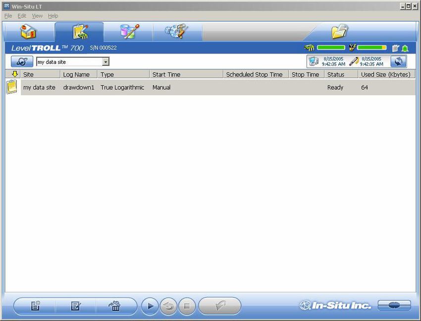
2

                                                      Contents
1 INTRODUCTION ........................................................................ 5
   System Description ..................................................................................................................... 5
   How to Use This Manual ............................................................................................................ 6
   Certification ................................................................................................................................. 6
   Unpacking and Inspection .......................................................................................................... 7
        Serial Number ..................................................................................................................... 7
   To Our Customers . . . ................................................................................................................ 8
   What We Provide ........................................................................................................................ 9
        Warranty Provisions ............................................................................................................ 9
   How to Contact Us ...................................................................................................................... 9
        To Obtain Repair Service (U.S.) ......................................................................................... 9
               Outside the U.S. ....................................................................................................... 10
        Guidelines for Cleaning Returned Equipment .................................................................. 11
2 SYSTEM COMPONENTS ............................................................ 13
   Body .......................................................................................................................................... 13
   Cable ......................................................................................................................................... 13
   Power Components .................................................................................................................. 17
   Installation Accessories ............................................................................................................ 18
   Control Software ....................................................................................................................... 19
   Product Specifications .............................................................................................................. 20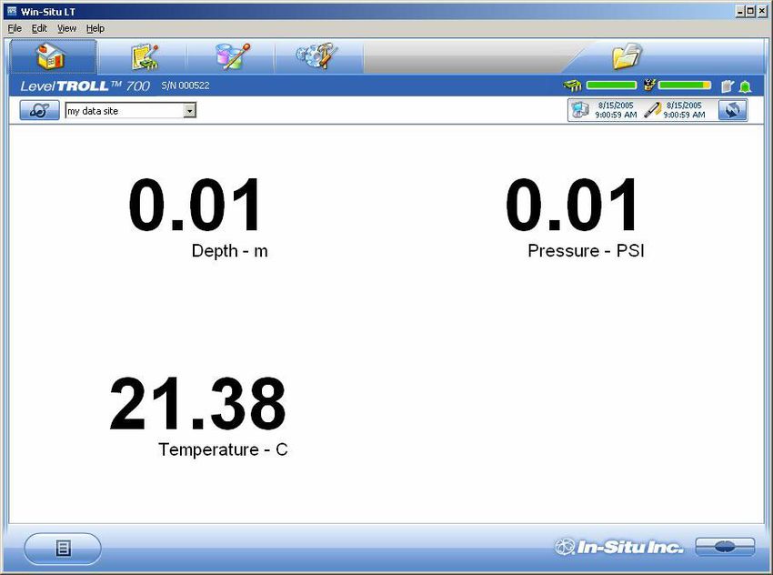
CONTENTS                                                                                                                                        3

3 GETTING STARTED .................................................................. 22
   A. Connect the Rugged Cable or Programming Cable to the Level TROLL ........................... 23
   B. Connect the TROLL Com to the Rugged Cable .................................................................. 26
   C. Connect to the Host PC ....................................................................................................... 27
   D. Install the Software .............................................................................................................. 28
   E. Launch the Software & Connect .......................................................................................... 29
        Set the Clock .................................................................................................................... 31
        Add a New Site ................................................................................................................. 32
        Prepare to Log Data ......................................................................................................... 35
   Disconnecting ........................................................................................................................... 37
4 ABOUT THE PRESSURE (LEVEL) SENSOR ..................................... 38
   Non-Vented (Absolute) vs. Vented (Gauged) Sensors ............................................................ 38
   Pressure, Depth, and Level ...................................................................................................... 39
   Configuring Depth and Level .................................................................................................... 40
   Pressure Sensor Calibration .................................................................................................... 42
        Factory Recalibration ........................................................................................................ 42
        Field Recalibration ............................................................................................................ 42
5 FIELD INSTALLATION ............................................................... 44
   Position the Level TROLL ......................................................................................................... 44
   Secure the Cable ...................................................................................................................... 45
   Installation Tips ......................................................................................................................... 45
   Stabilization Time ...................................................................................................................... 46
6 ANALOG, SDI-12 & MODBUS CONNECTIONS .............................. 47
   Desiccant .................................................................................................................................. 48
   Wiring ........................................................................................................................................ 48
   Power Connections .................................................................................................................. 53
   Communications ....................................................................................................................... 53
        Using Win-Situ .................................................................................................................. 53

Level TROLL 700 Operator’s Manual                                                                                                              08/05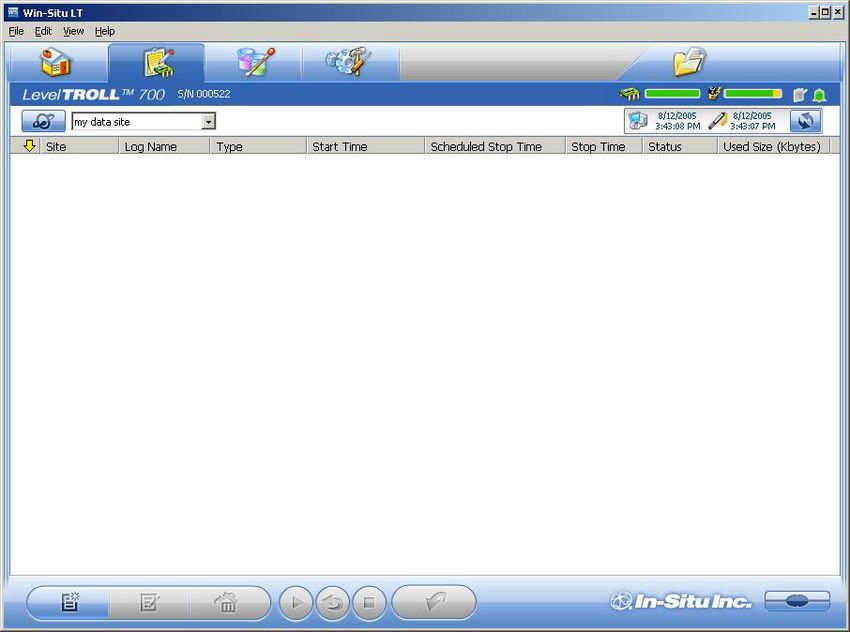
CONTENTS                                                                                                                                      4

7 CARE & MAINTENANCE ............................................................ 55
   Operating Considerations ......................................................................................................... 55
   Storage ..................................................................................................................................... 56
   General Maintenance ............................................................................................................... 56
        Cleaning—Body and Front End ........................................................................................ 56
        Twist-Lock Connectors ..................................................................................................... 57
        Cable Vent Tube (Vented Cable) ...................................................................................... 57
8 TROUBLESHOOTING ................................................................ 58
INDEX ....................................................................................... 60

Copyright © 2005 by In-Situ Inc. All rights reserved.
This document contains proprietary information which is protected by copyright. No part of this document may be
photocopied, reproduced, or translated to another language without the prior written consent of In-Situ Inc. The information in
this document is subject to change without notice. In-Situ Inc. has made a reasonable effort to be sure that the information
contained herein is current and accurate as of the date of publication.
In-Situ Inc. makes no warranty of any kind with regard to this material, including, but not limited to, its fitness for a particular
application. In-Situ will not be liable for errors contained herein or for incidental or consequential damages in connection with
the furnishing, performance, or use of this material. In no event shall In-Situ Inc. be liable for any claim for direct, incidental,
or consequential damages arising out of, or in connection with, the sale, manufacture, delivery, or use of any product.
In-Situ and the In-Situ logo, Win-Situ, Pocket-Situ, TROLL, Level TROLL, BaroTROLL, Twist-Lock Connector, TROLL Com,
MAXUM, Desicap, RuggedReader, and Rugged Cable are trademarks or registered trademarks of In-Situ Inc. Microsoft,
Windows, Excel, Internet Explorer, and ActiveSync are trademarks or registered trademarks of Microsoft Corporation.
Pentium is a registered trademark of Intel. Teflon and Delrin are registered trademarks of E. I. DuPont de Nemours and
Company. Viton is a registered trademark of DuPont Dow Elastomers. Kellems is a registered trademark of Hubbell Inc.
Other brand names and trademarks are property of their respective owners.

Level TROLL 700 Operator’s Manual                                                                                                            08/05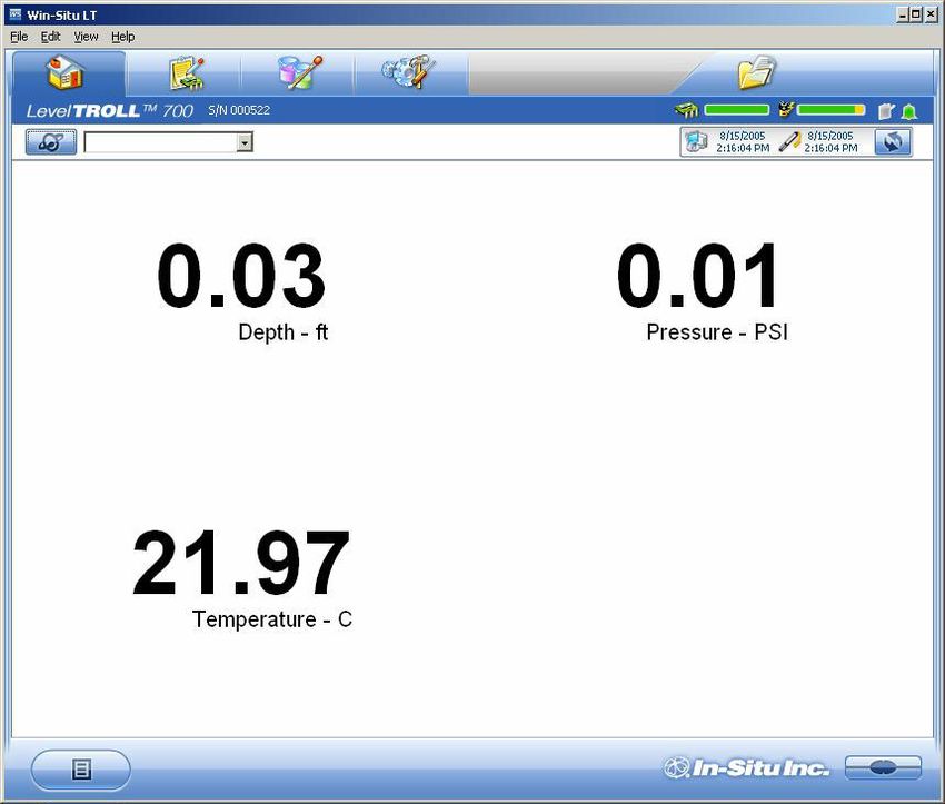
5

1 INTRODUCTION
  SYSTEM DESCRIPTION
  Your new Level TROLL 700 is a compact, modular system for measuring
  level and temperature in natural groundwater and surface water, as well
  as industrial, waste, and other installations. Components include the
  instrument body, deployment and communication cables, external power
  accessories, desiccants and other installation accessories, and software.
SECTION 1: INTRODUCTION                                                                       6

                     HOW TO USE THIS MANUAL
                     This operator’s manual is designed as both a start-up guide and a
                     permanent reference for the features, uses, and applications of the Level
                     TROLL 700.
                     Section 1: Introduction to the Level TROLL Operator’s Manual and to In-
                     Situ Inc. — Warranty Provisions — Instrument Repair & Return
                     Recommendations
                     Section 2: Components and features of the Level TROLL system —
                     Accessories — Product Specifications
                     Section 3: Getting Started — Attaching Cable — Installing & Launching
                     the Software — Connecting for the First Time — Setting the Clock —
                     Setting a Data Site — Preparing to Log Data
                     Section 4: About the Pressure (Level) Sensor: The two basic types of
                     pressure sensors — Factory and field calibration
                     Section 5: Field Installation — Guidelines and Precautions for Long-Term
                     Deployment of the Level TROLL
                     Section 6: Connecting for use with SDI-12, Analog (4-20 mA), and
                     Modbus loggers and controllers
                     Section 7: Care & Maintenance
                     Section 8: Troubleshooting
                     CERTIFICATION
                     The Level TROLL complies with all applicable directives per the CE and
                     FCC and was tested to the EN 55022 / ICES-003 / FCC specifications.

Level TROLL 700 Operator’s Manual                                                            08/05
SECTION 1: INTRODUCTION                                                                                            7

                               CONVENTIONS
                               Throughout this operator’s manual you will see the following symbols.

                                              The check mark highlights a tip about a convenient feature of the
                                              Level TROLL

                                              The exclamation point calls your attention to a requirement or
                                              important action that should not be overlooked

                               UNPACKING AND INSPECTION
          TIP: Please save     Your Level TROLL was carefully inspected before shipping. Check for any
          packing materials    physical damage sustained during shipment. Notify In-Situ and file a claim
          for future storage   with the carriers involved if there is any such damage; do not attempt to
and shipping of your Level
TROLL. The shipping
                               operate the instrument. Accessories may be shipped separately and
boxes have been                should also be inspected for physical damage and the fulfillment of your
performance-tested and         order.
provide protection for the
instrument and its             SERIAL NUMBER
accessories.
                               The serial number is engraved on the body of the Level TROLL. It is also
                               programmed into the instrument and displayed when the instrument is
                               connected to a computer running Win-Situ. We recommend that owners
                               keep a separate record of this number. Should your Level TROLL be lost
                               or stolen, the serial number is often necessary for tracing and recovery, as
                               well as any insurance claims. If necessary, In-Situ maintains complete
                               records of original owner’s names and serial numbers.

Level TROLL 700 Operator’s Manual                                                                                 08/05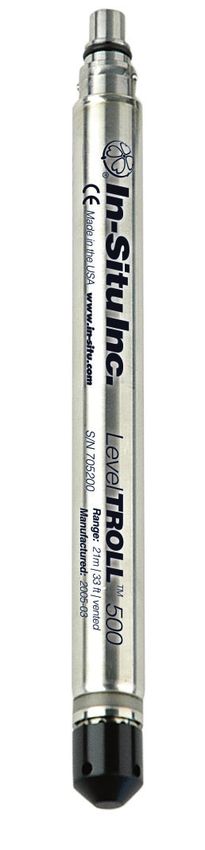
SECTION 1: INTRODUCTION                                                                           8

TO OUR CUSTOMERS . . .
Thank you for your purchase of an In-Situ product. We are glad you chose us and our products to
help you with your environmental monitoring needs. In-Situ Inc. has been designing and
manufacturing world-class environmental monitoring instrumentation for over 25 years in the Rocky
Mountains of the United States. As it was in the beginning, our expectation is that this product will
provide you with many trouble-free years of use. To that end, we pride ourselves on delivering the
best customer service and support possible—24 hours a day, 7 days a week. We believe that this
level of commitment to you, our customer, is imperative in helping you ensure clean, safe
groundwater and surface water resources across the globe. We also understand the need for
accurate, reliable assessments and we continue to make significant investments in Research and
Development to ensure that we deliver the latest product and technological innovations to support
your needs.
Whether you are gathering information about your body of water for a few moments, or over a
period of years, you can rely upon us to provide you with a quality product and outstanding
customer support at a fair price and have that product delivered to you when and where you need
it.
We want your experience with In-Situ Inc. to be pleasant and professional, whether you are renting
from us, or purchasing from us. We would be pleased to hear from you and learn more about your
needs, and your experiences with our products. Again, we thank you for choosing In-Situ Inc. and
we look forward to serving your needs now, and in the future.

                                            Bob Blythe, President and CEO
                                            In-Situ Inc.
                                            bblythe@in-situ.com
Level TROLL 700 Operator’s Manual                                                                08/05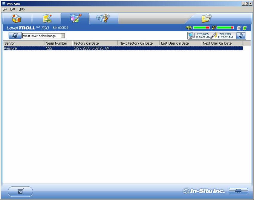
SECTION 1: INTRODUCTION                                                                           9

                     WHAT WE PROVIDE
                     WARRANTY PROVISIONS
                     In-Situ Inc. warrants all products sold, excluding batteries sold with such
                     products, against defects in materials and workmanship under normal
                     operating conditions. Consult the separate warranty for specific warranties
                     that may apply.
                     Maintenance & calibration plans as well as extended warranties are
                     available. Contact your In-Situ representative for complete information.

                     HOW TO CONTACT US
                     Technical Support:           800 446 7488
                                 Toll-free 24 hours a day in the U.S. and Canada
                     Address:                     In-Situ, Inc.
                                                  221 E. Lincoln Ave.
                                                  Fort Collins, CO 80524
                                                  USA
                     Phone:                       970 498 1500
                     Fax:                         970 498 1598
                     Internet:                    www.in-situ.com
                     TO OBTAIN REPAIR SERVICE (U.S.)
                     If you suspect that your Level TROLL is malfunctioning and repair is re-
                     quired, you can help assure efficient servicing by following these guidelines:
                     1. Call In-Situ Customer Service toll-free at 1-800-446-7488 or
                        1-970-498-1500. Have the product model and serial number handy.

Level TROLL 700 Operator’s Manual                                                                08/05
SECTION 1: INTRODUCTION                                                                               10

                              2. Be prepared to describe in detail the exact nature (symptoms) of the
                                 problem, including how the instrument was being used and the
                                 conditions noted at the time of the malfunction.
                              3. If service personnel determine that service is required, they will assign
                                 an RMA (return material authorization) number.
                              4. Clean the Level TROLL and cable. Decontaminate thoroughly if it has
                                 been used in a toxic or hazardous environment. See the Cleaning
                                 Guidelines and form later in this section.
                              5. Complete and sign a Decontamination & Cleaning Statement (print out
                                 the form on the next page) for each instrument.
                              6. Carefully pack your Level TROLL in its original shipping box, if
           If an instrument
           returned for          possible. Include a statement certifying that the instrument and cable
           servicing shows       have been decontaminated, and any supporting information.
evidence of having been
deployed in a toxic or        7. Send the package, shipping prepaid, to
hazardous environment,
                                 In-Situ, Inc.
Customer Service
personnel will require           Customer Service
written proof of decontami-      ATTN: RMA # (assigned no. here)
nation before they can           221 E. Lincoln Ave.
service the unit.
                                 Fort Collins, CO 80524
                              The warranty does not cover damage during transit. In-Situ recommends
                              the customer insure all shipments. Warranty repairs will be shipped back
                              prepaid.
                              Outside the U.S.
                              Contact your international In-Situ distributor for repair and service
                              information.

Level TROLL 700 Operator’s Manual                                                                      08/05
SECTION 1: INTRODUCTION 11
GUIDELINES FOR CLEANING RETURNED EQUIPMENT
Please help us protect the health and safety of our employees by cleaning
and decontaminating equipment that has been subjected to any potential
biological or health hazards, and labeling such equipment. Unfortunately,
we cannot service your equipment without such notification. Please
complete and sign the form below (or a similar statement certifying that
the equipment has been cleaned and decontaminated) and send it along
to us with each downhole instrument.
• A good cleaning solution, such as Alconox® (a glassware cleaning
product available from laboratory supply houses) is recommended.
• Clean all cabling. Remove all foreign matter.
• Clean cable connector(s) with a clean, dry cloth. Do not submerge.
• Clean the probe body—including the nosecone, restrictor, cable head,
and protective caps. Remove all foreign matter.
• Remove and clean any removable sensors. Rinse with deionized or
distilled water after cleaning.
If an instrument is returned to our Service Center for repair
or recalibration without a statement that it has been
cleaned and decontaminated, or in the opinion of our
Service Representatives presents a potential health or
biological hazard, we reserve the right to withhold service
until proper certification has been obtained.
Level TROLL 700 Operator’s Manual 08/05SECTION 1: INTRODUCTION 12
Decontamination & Cleaning Statement
Company Name __________________________________________ Phone ______________________
Address ______________________________________________________________________________
City __________________________________ State ________________ Zip _____________________
Instrument Type __________________________________ Serial Number _________________________
Contaminant(s) (if known) ________________________________________________________________
____________________________________________________________________________________
Decontamination procedure(s) used ________________________________________________________
____________________________________________________________________________________
Cleaning verified by ________________________________________ Title ________________________
Date _____________________________
Level TROLL 700 Operator’s Manual 08/0513
2 SYSTEM COMPONENTS
BODY
The Level TROLL’s all-titanium body, 18.3 mm (0.72 in) diameter,
includes pressure and temperature sensors, real-time clock, micro–
There are no
user-serviceable processor, sealed lithium battery, data logger, and memory. Options
parts in the Level include a variety of pressure (level) sensor ranges.
TROLL body.
CABLE
Several basic cable types are used in the Level TROLL system.
• Rugged Cable™, TPU-jacketed (Thermoplastic PolyUrethane)
• vented or non-vented
TIP: Cable • Halogen-Free vented or non-vented (LSZH-rated, low smoke
markings include zero halide)
VF = vent-free,
HF = halogen-free • Vented FEP* cable
• Communication cables for programming the device/downloading the
logged data
The Level TROLL 700 has a vented (gauged) pressure sensor and is
designed for deployment on vented cable.
* FEP (fluorinated ethylene propylene) is the generic equivalent of DuPont Teflon®SECTION 2: SYSTEM COMPONENTS 14
RUGGED CABLE™
Vented cable includes conductors for power and communication signals, a
strength member, a vent tube, and a Kellems® grip to anchor the Level
TROLL securely. The cable vent tube insures that atmospheric
pressure is the reference pressure applied to the sensor
diaphragm. The Desicap™ desiccant cap protects the cable
and electronics from condensation.
Uphole and downhole ends are identical bayonet-type Twist-
Lock™ connectors that mate with the Level TROLL body,
TROLL Com™ communication cable, desiccants, and other
accessories.
Non-vented cable, designed for use with non-vented
pressure/level sensors (absolute measurements), is available
for other products in the Level TROLL family.
Rugged Cable “Stripped & Tinned”
In place of the “uphole” Twist-Lock connector, this cable ends
in bare conductors for custom wiring to a logger or controller
using SDI-12, analog (4-20 mA), or Modbus communication
protocols. Vented cable includes an outboard desiccant pack
to protect against condensation.
Level TROLL 700 Operator’s Manual 08/05SECTION 2: SYSTEM COMPONENTS 15
Desicap™ Desiccant Cap
Vented cable includes a clear cap of indicating silica gel desic-
cant to protect the cable and electronics from condensation. The
desiccant is blue when active. It will absorb moisture from the
top down and for best results should be replaced before the
entire volume has turned pink. Replacements and refills are
available from In-Situ Inc. or your distributor.
MAXUM™ Desiccant
The optional high-volume desiccant pack may last up to 20 times
TIP: Protect new longer than the Desicap in humid environments. It attaches to the
desiccant from
moisture until Level TROLL cable in place of the Desicap. Refill kits are also
ready to use. available from In-Situ Inc. or your distributor.
Outboard Desiccant
Vented “stripped & tinned” cable includes an outboard
desiccant pack attached to the cable vent tube. Same size as
MAXUM. Replacements and refills are available.
Accessory Catalog No.
Desicap (replacement) ................................................................. 52230
Desicap refill kit ............................................................................. 52180
MAXUM ........................................................................................ 51810
Outboard Desiccant (replacement) .............................................. 51380
Refill kit for MAXUM & Outboard Desiccant pack ........................ 29140
Level TROLL 700 Operator’s Manual 08/05SECTION 2: SYSTEM COMPONENTS 16
COMMUNICATION CABLES
DB9 connector:
TROLL Com™ to computer
Vented polyurethane cable (0.9 m, 3 ft), connects the
Level TROLL's Rugged Cable to a PC’s serial port to
The DB9 end of display readings, to program the instrument for data
the TROLL Com collection, and to download the collected data.
is not submers-
ible. Converts the Level TROLL's RS485 signal to a Vent with
standard RS232 signal for communication via the hydrophobic
serial port on a host computer. Weatherproof, membrane
withstands a temporary immersion. Cable vents into Twist-Lock
unit, protected by a hydrophobic membrane. connector: to
Rugged Cable
The DB9 end of Programming Cable
the Program- Vented polyurethane or halogen-free polyurethane cable (1.8 m, 6 ft)
ming cable is
combines the functions of the Rugged Cable
not submersible.
and TROLL Com for profiling, programming,
and downloading; connects the Level
External
TROLL directly to a serial port; includes power jack
RS485/RS232 converter and external
Twist-Lock connector
power input jack. A good choice for DB9 connector
permanent connection to a PC, or
where external power is desirable.
Accessory Catalog No.
TROLL Com .................................................................................. 52170
Programming cable ...................................................................... 51840
Programming cable, halogen-free ................................................ 51850
USB to serial adapter ................................................................... 31090
Level TROLL 700 Operator’s Manual 08/05SECTION 2: SYSTEM COMPONENTS 17
POWER COMPONENTS
TIP: Win-Situ INTERNAL POWER
can display the
The Level TROLL 700 operates on 3.6 VDC, supplied by a completely
approximate
percentage of internal sealed, non-replaceable AA lithium battery. Typical battery life is 5 years
battery life remaining when or 2,000,000 data points, whichever occurs first. As a typical scenario,
the Level TROLL is with a 30 second sample rate, the battery will last 5.91 years and
connected to a computer.
the time to measure 2,000,000 data points will be 1.90 years.
EXTERNAL POWER
External Battery Pack
The sealed, submersible TROLL Battery Pack (lithium) supplies
TIP: When a 14.4 V. When this power source is connected, the Level TROLL will
Level TROLL is
used as an use the external battery source first and switch to the internal
Analog (4-20 mA), SDI-12, batteries when external battery power is depleted. For a Level
or Modbus device, power is TROLL 700, external batteries can be expected to last
supplied by the data logger approximately a year, regardless of sampling speed.
or controller to which the
Level TROLL is wired.
AC Adapter
Use only In- In-Situ’s AC adapter provides 24 VDC, 0.75 A, AC input 100-250 V,
Situ’s AC includes North American power cord. The Programming Cable includes an
adapter.
Damage to the
external power input for connection to this adapter.
Level TROLL caused by the Accessory Catalog No.
use of third-party converters
is not covered by the
External Battery Pack ................................................................... 51450
warranty. AC Adapter ................................................................................... 52440
Level TROLL 700 Operator’s Manual 08/05SECTION 2: SYSTEM COMPONENTS 18
INSTALLATION ACCESSORIES
• 1/4” NPT Adapter: allows Level TROLL installation in piping
• Twist-Lock™ Hanger: stainless steel hanger to suspend a non-
NPT Adapter vented Level TROLL or Baro TROLL while taking data; no venting,
no communication capabilities
• Cable Extender: connects two lengths of Rugged Cable
• Wellcaps, locking and vented
Twist-Lock Hanger
• Well Docks: top-of-well support for 2”, 4”, or 6” well
Accessory Catalog No.
NPT Adapter ................................................................................. 51470
Twist-Lock Hanger ........................................................................ 51480
Cable Extender ............................................................................. 51490
Cable Extender Locking Wellcap, 2” ...................................................................... 20360
Locking Wellcap, 2” vented .......................................................... 20370
Locking Wellcap, 4” ...................................................................... 20380
Locking Wellcap, 4” vented .......................................................... 20390
Top-of-well installation ring ....................................... WELLDOCK2”, 4”, 6”
Locking Wellcap
Well Dock
Level TROLL 700 Operator’s Manual 08/05SECTION 2: SYSTEM COMPONENTS 19
CONTROL SOFTWARE
Win-Situ™ is easy-to-use software for programming the Level TROLL.
Win-Situ provides instrument control for direct reads and profiling, long-
term data logging, data downloads, data viewing, data export to popular
spreadsheet programs, choice of units and other display options, battery/
memory usage tracking, interface to networks and telemetry. Available in
basic and Professional versions to suit customer needs.
Minimum system requirements: 400 MHz Pentium® II processor, 128 Mb
RAM, 100 Mb free disk space, Internet Explorer® 5.0 or higher, Win-
dows® 2000 Professional SP2 or better or Windows XP Professional SP1
or better.
Win-Situ connects through a serial COM port. If your computer does not
have one, a USB-to-serial adapter is available from In-Situ Inc. (Catalog
No. 31090).
Complete information on using the software is available from Win-Situ’s
Help menu.
Level TROLL 700 Operator’s Manual 08/05SECTION 2: SYSTEM COMPONENTS 20
PRODUCT SPECIFICATIONS
General
Wetted materials Titanium, acetal (nose cone)
Dimensions 21.6 mm (8.5 in) long, 18.3 mm (0.72 in) O.D.
Weight 0.2 kg (0.44 lb)
Operating temperature -20°C to +80°C (-4°F to +176°F)
Storage temperature -40°C to +80°C (-40°F to +176°F)
Pressure/Level
Sensor type Silicon strain gauge, vented
Material Titanium
Pressure ranges 5, 15, 30, 100, 300, 500 PSIG
Max. pressure 2X range
Burst pressure 3X range
Accuracy*
15°C ± 0.05 % full scale
-5 to +50°C ± 0.1 % full scale
-20 to -5 & +50 to +80°C ± 0.25 % full scale typical
Response time Dependent on software/firmware update rate: 4 per sec
Resolution 0.005 % full scale or better
Vented Level TROLL 700
Range Usable Depth
PSIG kPa Meters Feet
5 34.5 0-3.5 0-11.5
15 103.4 0-11 0-35
30 206.8 0-21 0-69
100 689.5 0-70 0-231
300 2068 0-210 0-692
500 3447 0-351 0-1153
* Accuracy with 4-20 mA output option: ± 0.25 % typical
Level TROLL 700 Operator’s Manual 08/05SECTION 2: SYSTEM COMPONENTS 21
Temperature
Sensor material Silicon
Range -20°C to +80°C (-4°F to +176°F)
Accuracy
0 to +50°C ± 0.1°C
-20 to 0 & +50 to +80°C ± 0.25°C
Response time T63 = 15 seconds, T90 = 30 seconds
Resolution 0.01°C or better
Communications
Output options RS-485 Modbus, RS-232 (via TROLL Com converter), SDI-12, 4-20mA
Logging
Memory 4 MB (at least 375,000 data points)
Log types Linear, Linear Average, Event, True Logarithmic, Fast Linear, Step
Fastest logging rate 4 samples/second (Modbus, SDI-12: 2 samples/second)
Max. no. of logs 50
Power
Battery 3.6 V, 2.25 Ah, lithium, sealed, not replaceable or rechargeable
Typical life 2,000,000 data points or 5 years (whichever comes first)
External power 8 to 36 VDC
External battery pack Lithium thionyl chloride batteries, 14.4 V, 2.4 g lithium
Cable
Jacket options Polyurethane, halogen-free (HF) polyurethane, FEP (generic Teflon)
Conductors 6 conductors, 24 AWG, polypropylene insulation
Diameter Cable, 6.7 mm (0.265 in); Connector, 18.5 mm (0.73 in)
Break strength 127 kg (280 lb)
Minimum bend radius 2X cable diameter (13.5 mm, 0.54 in)
Weight Polyurethane, regular & HF (vented): 14 kg/300 m (32.3 lb/1000 ft)
FEP (vented): 23 kg/300 m (52 lb/1000 ft)
Level TROLL 700 Operator’s Manual 08/0522
3 GETTING STARTED
This section provides a quick overview of the initial steps necessary to get
the Level TROLL ready to log data.
You will need—
• Level TROLL
• Cable
Rugged Cable and TROLL Com communication cable
or
Programming Cable
• Win-Situ software
• Desktop or laptop PCSECTION 3: GETTING STARTED 23
A. CONNECT THE RUGGED CABLE OR PROGRAMMING
CABLE TO THE LEVEL TROLL
1. Remove the protective caps from the Level TROLL and cable.
TIP: Retain the
dust caps to
protect the pins
and o-ring from damage
when cable is not attached.
Level TROLL
Cable
(or TROLL Com)
2. Take a moment to look at the connectors. Each has a flat side.
Flat Flat
Level TROLL
(or TROLL Cable
Com)
Note the pins on the body connector (one on each side) and the slots
on the cable connector (one on each side).
pin slot
Level TROLL 700 Operator’s Manual 08/05SECTION 3: GETTING STARTED 24
3. Slide back the sleeve on the cable connector.
4. Orient the “flats” so they will mate up, and insert the Level TROLL
connector firmly into the cable connector.
Level TROLL Cable
5. Slide the sleeve on the cable toward the Level TROLL body until the
pin on the body pops into the round hole in the slot on the cable
connector.
Level TROLL Cable
Level TROLL 700 Operator’s Manual 08/05SECTION 3: GETTING STARTED 25
6. Grasp the knurled (textured) section of the cable connector in one
hand and the Level TROLL body in the other. Push and twist firmly so
that the pin on the body connector slides along the slot on the cable
connector and locks securely into the other hole.
Be sure you
hear the “click.”
The “click”
ensures the cable is
securely attached. Level TROLL Cable
If you connected Rugged Cable, continue to step B. If you connected a
Programming Cable, skip to step C.
Level TROLL 700 Operator’s Manual 08/05SECTION 3: GETTING STARTED 26
B. CONNECT THE TROLL COM TO THE RUGGED CABLE
1. Remove the Desicap desiccant cap from the free end of the Rugged
Cable (if present) by grasping the knurled (textured) section of the
cable connector in one hand and the Desicap in the other. Twist in
opposite directions to unlock the Desicap from the cable.
2. Slide back the sleeve on the cable connector. Locate the “flats” on the
cable connector and the TROLL Com connector as before.
3. Orient the “flats” so they will mate up, and insert the TROLL Com
connector firmly into the cable connector.
4. Slide the metal sleeve on the cable toward the TROLL Com body until
Be sure you the pin on the body pops into the hole in the slot on the cable connec-
hear the “click.” tor.
The “click”
ensures the cable is 5. Grasp the knurled (textured) section of the cable connector in one
securely attached. hand and the TROLL Com body in the other. Push and twist firmly so
that the pin on the body slides along the slot on the cable connector
and snaps securely into the other hole.
Level TROLL 700 Operator’s Manual 08/05SECTION 3: GETTING STARTED 27
C. CONNECT TO THE HOST PC
Attach the DB9 connector on the TROLL Com or Programming Cable to a
PC’s standard 9-pin RS232 serial port.
TIP: A serial port
is required. If
your computer Serial port
does not have one, a USB-
to-serial adapter is available PC
from In-Situ Inc. (Catalog
No. 31090).
Programming Cable
TROLL Com
123
12
Level TROLL 12
Rugged Cable
123
Level TROLL
Level TROLL 700 Operator’s Manual 08/05SECTION 3: GETTING STARTED 28
D. INSTALL THE SOFTWARE
For communication using a desktop or laptop PC, install Win-Situ:
1. Insert the Win-Situ installation CD in the appropriate drive of your
computer.
• If the CD-ROM drive is set to Auto-Play, the installation program will
start automatically.
• If necessary, choose Run from the Windows Start Menu and type
D:\Setup, where D is your CD-ROM drive letter.
2. Follow the instructions to install the program to your local hard drive.
We recommend you select when prompted:
• the default Destination Folder — C:\Program Files\InSitu\WinSitu
• a “Complete” setup type
• Win-Situ shortcut on the desktop
Level TROLL 700 Operator’s Manual 08/05SECTION 3: GETTING STARTED 29
E. LAUNCH THE SOFTWARE & CONNECT
1. Start Win-Situ by double-clicking the shortcut created on the desktop
during installation.
2. When the Win-Situ application window opens, select File menu >
Settings and check your PC’s COM port (usually COM 1 for direct
serial port connection). Click the “OK” button .
3. Click the “Connect” button to connect to the Level TROLL.
File menu
Settings
COM port
OK
Click here to
connect
Level TROLL 700 Operator’s Manual 08/05SECTION 3: GETTING STARTED 30
4. The software will connect to the Level TROLL and display current level/
depth, pressure, and temperature readings.
Tabs
Dashboard
Home tab Setup tab
TIP: To change
the units: Click
the Setup tab.
Select units for each
parameter in the Parameter
Configuration section of the
Setup screen. Return to the
Home tab and refresh the
readings with the “Read”
button.
“Read” button Device is connected
Control Panel
Note the Tabs at the top of the screen— this is the ‘Home” tab, which
displays current readings from the connected device.
The Dashboard (status area) below the tabs displays information about
the Level TROLL, including its model and serial number, battery and
memory capacity, the device clock and the computer clock, and current
Site setting.
The Control Panel at the bottom contains action buttons. You can
update the readings by clicking the “Read” button.
Level TROLL 700 Operator’s Manual 08/05SECTION 3: GETTING STARTED 31
Now you’re ready to give the Level TROLL some specific information
through the software. Win-Situ provides many options. At a minimum:
• set the Level TROLL clock
• define the site where the Level TROLL will collect data
• enter data logging instructions
A brief overview is provided here. For more detailed information, see Win-
Situ’s Help menu.
SET THE CLOCK
Data collection schedules depend on the device’s real-time clock. Both the
device clock and the system (PC) clock are shown on the dashboard
when the device is connected. The clocks update every 2 seconds. If the
device clock is more than 2 seconds off the system clock, the device clock
is displayed in red. To synchronize the clocks, click the Sync button.
Site
Clock Sync
button
Device clock
PC clock
Level TROLL 700 Operator’s Manual 08/05SECTION 3: GETTING STARTED 32
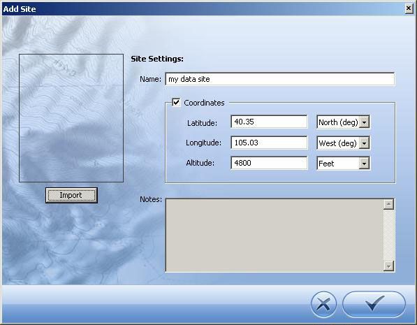
ADD A NEW SITE
Logged data are organized by the sites where the data were logged. For
easy data file management, downloaded data files are saved to a folder
on your PC that has the same name as the site.
To specify a site for the connected Level TROLL:
1. Select File menu > New Site.
2. When the Site List is displayed, click the “New” button.
TIP: A default
site is supplied
and may be
used, but it does not
provide any specific
information about the place
where the data were
logged. For complete
information on Sites, see
Win-Situ’s On-Line Help.
“New” button
Level TROLL 700 Operator’s Manual 08/05SECTION 3: GETTING STARTED 33
3. In the Add Site dialog, enter a name for the site. A short, descriptive
name is best—for example, a project, well, water body, gauging
station, town, nearby landmark, etc. Length is limited to 32 characters.
4. Enter the optional site coordinates if you wish. They are used to
uniquely identify a data location. They are not used elsewhere by the
software.
5. Click “OK” to add the new site to the site database in the Win-Situ
working directory on your computer. Now it is available to use in any
connected device.
“OK” button
Level TROLL 700 Operator’s Manual 08/05SECTION 3: GETTING STARTED 34
6. The Site List will be displayed again, with your new site.
7. Select (highlight) your new site and click the “Set” button—it looks like
a target—to store this site in the connected Level TROLL.
Tip: You can
create as many
sites as you like
with the “New” button. Only
one site at a time is stored
in the Level TROLL.
“Set” button
Level TROLL 700 Operator’s Manual 08/05SECTION 3: GETTING STARTED 35
PREPARE TO LOG DATA
1. To prepare the device to log data, first select the Logging tab.
2. Click the “New” button.
Logging tab
“New” button
TIP: For more
complete
information on
setting up data logs, see
Win-Situ’s On-Line Help. The Logging Setup Wizard will prompt you through the configuration of a
data log—including the site, log name, parameters to measure, sample
schedule, start time, stop time (optional), output (pressure, depth, or water
level with a reference), and other options.
Level TROLL 700 Operator’s Manual 08/05SECTION 3: GETTING STARTED 36
To Start logging:
A “Pending” (scheduled) log will start at its programmed time
You can start a “Ready” (manual) log at any time
while connected by selecting the log and pressing “Start”
To Stop logging:
Select the log and press the “Stop” button
Or suspend (temporarily stop) it with the “Pause” button
TIP: As an To Download the log to the connected PC:
alternative to the
log control Select the log and press the “Download” button
buttons, right-click a log to
display a short context
menu of available actions.
Logging tab “Ready” log
“Start” button
Log control buttons
Level TROLL 700 Operator’s Manual 08/05SECTION 3: GETTING STARTED 37
DISCONNECTING
After the Level TROLL is programmed to log data, you're ready to
• Exit the software (File menu > Exit).
• Disconnect the TROLL Com from the cable connector, by grasping
the knurled (textured) section of the cable connector in one hand
and the TROLL Com in the other. Twist in opposite directions to
unlock the TROLL Com from the cable.
• Place the Desicap desiccant cap on the cable connector.
• Install the instrument in its field location. See Section 5 for guide-
lines.
Level TROLL 700 Operator’s Manual 08/0538 4 ABOUT THE PRESSURE (LEVEL) SENSOR A pressure transducer senses changes in pressure, measured in force per square unit of surface area, exerted by water or other fluid on an internal media-isolated strain gauge. Common measurement units are pounds per square inch (PSI) or newtons per square meter (pascals). NON-VENTED (ABSOLUTE) VS. VENTED (GAUGED) SENSORS A non-vented or “absolute” pressure sensor measures all pressure forces exerted on the strain gauge, including atmospheric pressure. Its units are PSIA (pounds per square inch “absolute”), measured with respect to zero pressure. Non-vented pressure measurements are useful in vacuum testing, in short-term testing when atmospheric pressure would not be expected to change, in very deep aquifers where the effects of atmospheric pressure are negligible, and in unconfined aquifers that are open to the atmosphere.
SECTION 4: PRESSURE (WATER LEVEL)                                                           39

                     With vented or “gauged” pressure sensors, a vent tube in the cable
                     applies atmospheric pressure to the back of the strain gauge. The basic
                     unit for vented measurements is PSIG (pounds per square inch “gauge”),
                     measured with respect to atmospheric pressure. Vented sensors thus
                     exclude the atmospheric or barometric pressure component.
                     This difference between absolute and gauged measurements may be
                     represented by a simple equation:

                                         Pgauge = Pabsolute - Patmosphere
                     The Level TROLL 700’s pressure sensor is a vented (gauged) sensor.
                     PRESSURE, DEPTH, AND LEVEL
                     Output options for pressure measurement are completely software-
                     selectable. Each log configuration presents the following choices:
                        • Pressure in PSI or kPa
                        • Depth
                        • Water Level with a reference (an “offset”)
                           Surface Elevation reference
                           Distance to Water reference
                     Pressure is a simple check box. For depth or level, the software presents
                     additional options:
                     • the type of Level measurement you wish to log.
                     • the conversion from pressure (in PSI) to depth or level (in feet or
                       meters), including a very accurate conversion that compensates
                       pressure readings for fluid density, altitude, and latitude.

Level TROLL 700 Operator’s Manual                                                            08/05
SECTION 4: PRESSURE (WATER LEVEL) 40
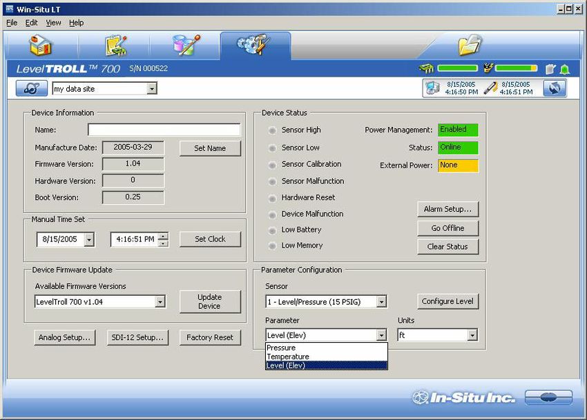
CONFIGURING DEPTH AND LEVEL
TIP: When you This procedure stores the configuration settings in the Level TROLL.
configure level When setting up a log, the same options are presented.
using the Setup
tab, the settings are stored 1. While connected to the Level TROLL in software, click the Setup tab.
in the Level TROLL and are
available for use in Modbus, 2. In the Parameter Configuration section of the Setup screen, select the
SDI-12, and analog Level parameter, then click Configure Level. The Level parameter
communications, as well as
in Win-Situ. Different shown is the one currently stored in the device (device’s default or the
configuration may be most recent choice).
selected when setting up a
log.
Setup tab
Parameter
Configuration
area
Select Level Click Configure Level
Level TROLL 700 Operator’s Manual 08/05SECTION 4: PRESSURE (WATER LEVEL) 41
3. In the Level Configuration Wizard, select the options you want. For
more information, see Win-Situ’s On-Line Help.
Level TROLL 700 Operator’s Manual 08/05SECTION 4: PRESSURE (WATER LEVEL) 42
PRESSURE SENSOR CALIBRATION
FACTORY RECALIBRATION
Pressure sensor accuracy can be adversely affected by improper care and
handling, lightning strikes and similar surges, exceeding operating
temperature and pressure limits, physical damage or abuse, as well as
normal drift in the device’s electronic components. Aside from damage to
the sensor, the need for factory recalibration is dependent upon the
amount of drift a customer is willing to tolerate. Factory calibration every
12-18 months is recommended. Contact In-Situ Customer Service for
information on the factory maintenance and calibration plan.
FIELD RECALIBRATION
The following procedure may be used, with caution, to “zero” the offset of
a vented pressure sensor to correct for electronic drift. The drifted offset is
visible when the sensor is in air and reading other than zero.
It is recommended you do not zero the offset if it is outside the specified
accuracy of your pressure sensor, as shown in the table below. If the
reading in air deviates from zero by more than the amounts shown, you
may want to consider a factory recalibration.
Sensor Accuracy Acceptable Offset
range (-5°C to +50°C) from zero
5 PSI ± 0.1% FS ± 0.005 PSI
15 PSI ± 0.1% FS ± 0.015 PSI
30 PSI ± 0.1% FS ± 0.03 PSI
100 PSI ± 0.1% FS ± 0.10 PSI
300 PSI ± 0.1% FS ± 0.30 PSI
500 PSI ± 0.1% FS ± 0.50 PSI
Level TROLL 700 Operator’s Manual 08/05SECTION 4: PRESSURE (WATER LEVEL) 43
Field Recalibration Procedure
1. With the Level TROLL connected in software, select the Calibrate tab.
2. Select the pressure sensor and click the Calibrate button.
You will be prompted to ensure the device is in air.
3. With the device in air, click Calibrate.
The current pressure reading will be set to zero.
Calibrate tab
Calibrate button
Level TROLL 700 Operator’s Manual 08/0544
5 FIELD INSTALLATION
POSITION THE LEVEL TROLL
Lower the Level TROLL gently to approximately the desired depth.
Position the instrument below the lowest anticipated water level, but not
so low that its range might be exceeded at the highest anticipated level.
Refer to the tables below for usable depth.
Vented Level TROLL 700
Range Usable Depth
PSIG kPa Meters Feet
5 34.5 0-3.5 0-11.5
15 103.4 0-11 0-35
30 206.8 0-21 0-69
100 689.5 0-70 0-231
300 2068 0-210 0-692
500 3447 0-351 0-1153SECTION 5: FIELD INSTALLATION 45
CHECK THE INSTRUMENT'S DEPTH
At this point, if convenient, you can connect the Level TROLL to a
PC, start Win-Situ or Pocket-Situ, and take a reading. If the
instrument is at the desired depth, secure it in position as
suggested below. If not, reposition the Level TROLL as necessary.
If you requested the software to “Remind me later” to set a Level
Reference, enter the level reference after installation when
prompted.
SECURE THE CABLE
The Rugged Cable has a handy device called a Kellems® grip
near the surface end. You can slide it along the cable to the
desired position by compressing it. When you pull on it, it tightens
and stops sliding. You may need to pull on both ends of the
Kellems grip to properly tighten it and keep it from slipping.
Use the loop of the Kellems grip to anchor the cable to a
convenient stationary object. It works well with In-Situ’s “well dock”
installation ring. Simply insert the loop into the locking clip on the
well dock, and position the assembly on the top of a well.
INSTALLATION TIPS
Never let a probe “free fall” down a well. The resulting shock
Kellems grip wave when it hits the water surface can damage the strain
gauge (the “waterhammer” effect).
It is always wise to check the level of water above the probe,
then move it and read again to be sure that the probe is giving
a reasonable reading and showing change. It might not be
Level TROLL 700 Operator’s Manual 08/05SECTION 5: FIELD INSTALLATION 46
located where you think it is — for example, it could be wedged against
the casing with a loop of cable hanging below it. A probe in such a
position might become dislodged and move while logging, giving a
false change in level. A secure placement is critical to accurate
measurements.
Do not allow the vented cable to kink or bend. If the internal vent tube is
obstructed, water level measurements can be adversely affected. The
The minimum recommended minimum bend radius is 13.5 mm (0.54 in), which is
bend radius for
vented cable is
twice the cable diameter.
13.5 mm (0.54 in).
For accurate measurements, the instrument should remain immobile
while logging data.
Be sure the “uphole” cable end is capped—Desicap on the vented
Do not cable connector, soft dust cap on non-vented cable—and positioned
submerge the above the highest anticipated water level. Avoid areas that may flood.
connector at
the uphole end of the STABILIZATION TIME
cable.
Allow the Level TROLL to stabilize to the water conditions for about an
hour before logging data. A generous stabilization time is always
desirable, especially in long-term deployments. Even though the cable is
shielded, temperature stabilization, stretching, and unkinking can cause
apparent changes in the probe reading. If you expect to monitor water
levels to the accuracy of the probe, it’s worth allowing the extra time for
the probe to stabilize to its environment.
Level TROLL 700 Operator’s Manual 08/0547
6 ANALOG, SDI-12 &
MODBUS CONNECTIONS
The Level TROLL may be connected to a controller or logger for
communication via:
• Analog (4-20 mA)
• SDI-12
• RS-485 Modbus
• RS-232 Modbus (with a customer-supplied converter)
Rugged Cable™ Stripped & Tinned has a Twist-Lock™ connector on one
end to mate with the Level TROLL body. The uphole end terminates in
bare wires for connection to a PLC or data logger.SECTION 6: ANALOG, SDI-12, MODBUS 48
DESICCANT
Vented cable includes removable
outboard desiccant to protect the cable Outboard desiccant
vent tube and Level TROLL electronics is attached to cable
vent tube
from condensation in high-humidity
environments.
The desiccant may be removed from the and secured
vent tube, if needed, to trim the conductor to cable with
wires. Pull the vent tube extender off the strap
cable vent tube to remove, replace
desiccant after trimming and connecting
wires.
WIRING
Refer to diagrams on the following pages. Trim back and insulate unused
wires.
Rugged Cable (TPU) FEP Cable
Signal Color Pin Signal Color
Gnd/Return BLACK 6 M2 Gnd/Return BLACK
Ext Power RED 5 M1 M3 Ext Power RED
4-20 mA BROWN 4 F6 F4 4-20 mA BROWN
RS485(–) GREEN 3 F5 RS485(–) GREEN
RS485(+) BLUE 2 RS485(+) ORANGE
SDI-12 WHITE 1 SDI-12 YELLOW
Level TROLL 700 Operator’s Manual 08/05SECTION 6: ANALOG, SDI-12, MODBUS 49
ANALOG (4-20 mA) 2 WIRE
PLC or Data Logger
4-20 mA BROWN
+ 12-36 VDC
GND/RETURN BLACK
- SIGNAL
123
123
Level
TROLL
Level TROLL 700 Operator’s Manual 08/05SECTION 6: ANALOG, SDI-12, MODBUS 50
SDI-12 3 WIRE
Data Logger
EXT PWR RED
9.6-16 VDC
GND/RETURN BLACK
SDI-12 WHITE*
* Yellow for FEP cable
123
123
SDI-12
sensor
Level TROLL 700 Operator’s Manual 08/05SECTION 6: ANALOG, SDI-12, MODBUS 51
MODBUS MASTER
with RS-485 built in
Digital PLC
EXT PWR RED
12-36 VDC*
GND/RETURN BLACK
RS-485 (–) GREEN
RS-485 (+) BLUE**
* Optional but highly recommended
** Orange for FEP cable
123
123
Modbus
Slave
Level TROLL 700 Operator’s Manual 08/05SECTION 6: ANALOG, SDI-12, MODBUS 52
MODBUS MASTER
with RS-232 built in (converter required)
Digital PLC EXT PWR RED
12 VDC*
GND/RETURN BLACK
RS-232 (TXD) Gnd +12V RS-485 (–) GREEN
RS-232 (RXD) RS-485 (+) BLUE**
Converter
* Voltage limited by converter
**Orange for FEP cable
EXT PWR RED***
CONVERTER GND/RETURN BLACK***
Port-Powered RS-485 converter,
RS-485 (–) GREEN 123
123
such as B&B Electronics Model
485SD9TB
RS-485 (+) BLUE**
PIN 5 GND Modbus
RS-232
RS-485
Slave
DB9F
PIN 3 TXD
+12V
GND
GND
TD(B)
TD(A)
PIN 2 RXD
***Required if port power is not available
Level TROLL 700 Operator’s Manual 08/05SECTION 6: ANALOG, SDI-12, MODBUS 53
POWER CONNECTIONS
The Red wire provides power for Modbus and SDI-12 modes. The Brown
wire provides power for the 4-20 mA mode. If power is present on the
Brown wire and not on the Red wire, the device enters the 4-20 mA mode
automatically and stays in the 4-20 mode until power is removed from the
Brown wire or is applied to the Red wire. The Red wire has priority — if
power is applied to both wires at the same time, the device will operate in
Modbus or SDI-12 modes but not in 4-20.
COMMUNICATIONS
The device automatically switches between Modbus and SDI-12 modes
depending on which of the two interfaces has activity. Modbus and SDI-12
cannot be used at the same time — whichever one is currently in use will
block communication on the other.
USING WIN-SITU
Win-Situ provides options for configuring analog/SDI-12 communications
(Setup tab) and Modbus communications (File menu > Settings). In
addition, the Level TROLL is capable of internal logging (programmed in
Win-Situ) while participating in a Modbus, SDI-12 or analog network.
However, Win-Situ cannot communicate with the Level TROLL while it is
transmitting Modbus, SDI-12 or analog data, and conversely, the
instrument cannot receive or respond to Modbus, SDI-12 or analog
commands while connected to a PC serial port.
This “redundant logging” feature means
• if the PLC or recorder somehow “loses” data, the Level TROLL data
can be retrieved using Win-Situ.
Level TROLL 700 Operator’s Manual 08/05SECTION 6: ANALOG, SDI-12, MODBUS 54
• if the PLC or recorder ceases to function due to power loss, the Level
TROLL will continue to collect data using its own internal batteries and
clock.
A port-powered RS-485 converter like that shown for Modbus connections
may be used for temporary connection of the Level TROLL to a serial port
on a PC.
Level TROLL 700 Operator’s Manual 08/0555 7 CARE & MAINTENANCE OPERATING CONSIDERATIONS The Level TROLL has been designed to withstand harsh field conditions. However, as with any electronic instrument, it can be permanently damaged if used outside its operating specifications. TEMPERATURE The Level TROLL is designed to operate within a temperature range of -20°C to +80°C (-4°F to 176°F). PRESSURE RANGE The Level TROLL can withstand pressures of up to two times (2X) the rated range of the pressure sensor without damage, although it may not read correctly at such pressure. If the pressure range is exceeded by 3X, the sensor will be destroyed. CALIBRATION Accuracy can be adversely affected by improper care and handling, lightning strikes and similar surges, exceeding operating temperature and pressure limits, physical damage or abuse. Factory calibration every 12- 18 months is recommended. Contact In-Situ Customer Service for information on the factory maintenance and calibration plan.
SECTION 7: CARE & MAINTENANCE                                                                                  56

                             STORAGE
                             Store the Level TROLL clean and dry. Place the protective red dustcap on
                             the cable end, or store with cable attached to protect the connector pins
                             and o-ring.
                             Store the instrument where it will be safe from mechanical shocks that
                             may occur, such as rolling off a bench onto a hard surface.
                             Protect the instrument from temperature extremes. Store within a
                             temperature range of -40°C to +80°C (-40°F to +176°F).
                             GENERAL MAINTENANCE
                             CLEANING—BODY AND FRONT END
            When the nose
            cone is          Clean the Level TROLL body with water and a soft brush, or soak
            removed, the     overnight in a mild acidic solution, such as household vinegar, or clean in
sensitive pressure sensor
                             an ultrasonic bath with a good concentrated detergent solution.
diaphragm is completely
exposed. Do not touch
                             If the ports in the front end are clogged with silt or mud, try the following:
this area with any object!
Replace the nose cone as     • Swish the instrument vigorously in a bucket of clean water
soon as possible.
                             • Apply a gentle squeeze of water from a wash bottle
                             • In severe cases, remove the nose cone and clean out the holes with a
                               soft brush or pipe cleaner
    Nose cone in place       To avoid damage to the pressure sensor diaphragm, do not insert any
                             object into the sensor opening or attempt to dig out dirt or other materials.
                                            Damage caused by digging or scraping in the pressure sensor
                                            opening to remove silt, mud, etc. is not covered by the warranty.

    Nose cone removed        If contamination cannot be removed using the recommendations above,
                             please contact In-Situ Inc. for cleaning.

Level TROLL 700 Operator’s Manual                                                                               08/05
You can also read