SLA5800 Series Elastomer Sealed,
Thermal Mass Flow Controllers & Meters
Installation & Operation Manual
←
→
Page content transcription
If your browser does not render page correctly, please read the page content below
SLA5800 Series Elastomer Sealed, Thermal Mass Flow Controllers & Meters Installation & Operation Manual
Essential Instructions
                                                        Read before proceeding!

and integrated into your safety program when installing, operating and maintaining Brooks Instrument products.
   To ensure proper performance, use qualified personnel to install, operate, update, program and maintain the product.

     for local sales office contact information. Save this instruction manual for future reference.

            this warning can result in serious personal injury and / or damage to the equipment.
     If you do not understand any of the instructions, contact your Brooks Instrument representative for clarification.
     Follow all warnings, cautions and instructions marked on and supplied with the product.

     result in serious personal injury and / or damage to the equipment.

     Connect all products to the proper electrical and pressure sources.

     and outlet connections. If no leaks are present, bring the system up to the operating pressure.

     operation of your process at risk. Look-alike substitutions may result in fire, electrical hazards or improper operation.

           maintenance is being performed by qualified persons.

     drained.Failure to do so mayresult inthermalexpansion of theliquidthat canrupturethe device and may cause personal injury.

                                            European Pressure Equipment Directive (PED)
 Allpressureequipment with aninternalpressuregreater than 0.5 bar(g) and a sizelarger than25mmor 1" (inch) falls under thePressureEquipment Directive(PED).
 • The Specifications Section of this manual contains instructions related to the PED directive.
 • Products described in this manual are in compliance with EN directive 2014/34/EU.
 • All Brooks Instrument Flowmeters fall under fluid group 1.
 • Products larger than 25mm or 1" (inch) are in compliance with PED category I, II or III.
 • Products of 25mm or 1" (inch) or smaller are Sound Engineering Practice (SEP).

                                           European Electromagnetic Compatibility (EMC)

Compatibility (EMC directive 2014/30/EU).
Special attention however is required when selecting the signal cable to be used with CE marked equipment.
Quality of the signal cable, cable glands and connectors:
Brooks Instrument supplies a limited selection of high quality cable(s) which meets the specifications for CE certification.
If you provide your own signal cable you should use a cable which is overall completely screened with a 100% shield.

The cable screen should be connected to the metal shell or gland and shielded at both ends over 360 Degrees.
                                               Card Edge Connectors are standard non-metallic. The cables used must be screened with
100% shield to comply with CE certification. The shield should be terminated to an earth ground. For additional instruction regarding
Protective Earth (PE) Connections please refer to Section 2, Electrical Interface page 29.
For pin configuration: Please refer to the enclosed Instruction Manual.

                                                       ESD (Electrostatic Discharge)

Handling Procedure:
   Power to unit must be removed.

    removed or adjusted.

  installation. Removed boards must immediately be placed in protective container for transport, storage or return to factory.
Comments

devices. Damaged components, even though they appear to function properly, exhibit early failure.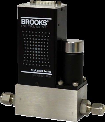
Contents

Section 1 Introduction
  Purpose ................................................................................................................................................ 1
  Specifications ..................................................................................................................................... 3-5
  Certifications ...................................................................................................................................... 6-7
  Reference Conditions ............................................................................................................................ 8
  Biotech Option Packages ...................................................................................................................... 8
  PC-based Support Tools ....................................................................................................................... 8
  Fast Response Performance ................................................................................................................. 9
  Calibration Selection ............................................................................................................................. 9
  Selectable Soft Start.............................................................................................................................. 9

Section 2 Installation
  Receipt of Equipment .......................................................................................................................... 18
  Recommended Storage Practice ......................................................................................................... 18
  Return Shipment ................................................................................................................................. 18
  Transit Precautions ............................................................................................................................. 19
  Removal from Storage ........................................................................................................................ 22
  Gas Connections................................................................................................................................. 22
  In-Line Filter ................................................................................................................................... 19-22
  Electrical Interface.......................................................................................................................... 22-27
  Operation Check Procedure (Analog I/O)............................................................................................. 28
  Operation Check Procedure (Digital I/O) ............................................................................................... 29
  Bus/Network (DeviceNet, Profibus, Foundation Fieldbus, EtherCAT)..................................................... 29

Section 3 Operation
  Features (Standard and Bitoech) ..................................................................................................... 30-31
  Analog I/O Mode of Operation ........................................................................................................ 31-32
  RS485 Communications Features (Analog versions only) .................................................................... 33
  EtherNET/IPTM Communications Features............................................................................................ 34
  DeviceNet Communications Features ...........…………………………………………………………………34
  Profibus Communications Features ...........………………………………………………………………….35
  EtherCAT Communications Features...... …………………………………………………………………..35-36
  Alarms (Analog versions only) ............................................................................................................. 36
  Alarms (Analog versions only) Configuration Attributes ................................................................... 36-37
  Diagnostic Alarms (Analog versions only) ............................................................................................ 38
  General Alarms (Analog versions only) ........................................................................................... 38-39
  Calibration/Configuration Sets .............................................................................................................. 39
  Special Features .................................................................................................................................. 39
  Setpoint Ramping ................................................................................................................................. 40
  Low Setpoint Command Cutoff ............................................................................................................. 40
  Low Flow Output Cutoff ........................................................................................................................ 40
  Adaptive Control ................................................................................................................................... 40
  Flow Totalizer .................................................................................................................................................... 40
  PC-based Support Tools .................................................................................................................................. 40
Contents

Section 4 Maintenance & Troubleshooting
  Maintenance and Troubleshooting ....................................................................................................... 41
  Troubleshooting Analog or Digital ................................................................................................... 42-43
  System Checks .............................................................................................................................. 43-46
  Cleaning Procedures ........................................................................................................................... 46
  Calibration Procedure .......................................................................................................................... 47

Warranty, Local Sales/Service Contact Information ...................................................................... Back Cover

Figures
   1-1   General Wiring ........................................................................................................................... 9
   1-2   Response Performance of Brooks Digital MFC ......................................................................... 10
   1-3   Linear Ramp-up and/or Ramp-down from 200% Per Second Down to 0.5%
         Per Second Setpoint Change ................................................................................................... 10
   1-4   SLA5800 Series RS485 15-Pin Analog Connector and Pinouts ................................................. 11
   1-5   SLA5800 Series Profibus Connections and Pinouts .................................................................. 12
   1-5.5 SLA5800 Series EtherNet/IP Connections and Pinouts.............................................................. 13
   1-6   SLA5800 Series DeviceNet Connections and Pinouts ................................................................ 14
   1-7   SLA5800 Series EtherCAT Connections and Pinouts ................................................................. 15
   1-8   Dimensions ............................................................................................................................... 16
   1-9   Dimensions .............................................................................................................................. 17
   2-1   RS485 D-Connector Shielded Cable Hookup Diagram, Voltage I/O Version .................................. 24
   2-2   Recommended Wiring Configuration for Current Signals (Non-Isolated Power Supply) ............. 25
   2-3   Recommended Wiring Configuration for Current Signals (Isolated Power Supply) ..................... 25
   2-4   RS485 Multidrop Interconnection TMFs and PC........................................................................ 26
   3-1   Externally Accessible Adjustment (Zero Button) for all Meters/Controllers.................................. 33
   4-1   Bench Troubleshooting Circuit .................................................................................................. 44

Tables
  1-1         SLA5800 Series Specifications ................................................................................................... 3
  1-2         SLA5800 Series Biotech ............................................................................................................ 3
  1-3         SLA5800 Series Electrical Specifications .................................................................................... 5
  1-4         SLA5800 Series Certifications .................................................................................................... 6
  2-1         Recommended Filter Size ........................................................................................................ 19
  4-1         Sensor Troubleshooting............................................................................................................ 44
  4-2         Troubleshooting .................................................................................................................. 45-46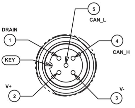
Section 1 Introduction
Section 1: Introduction
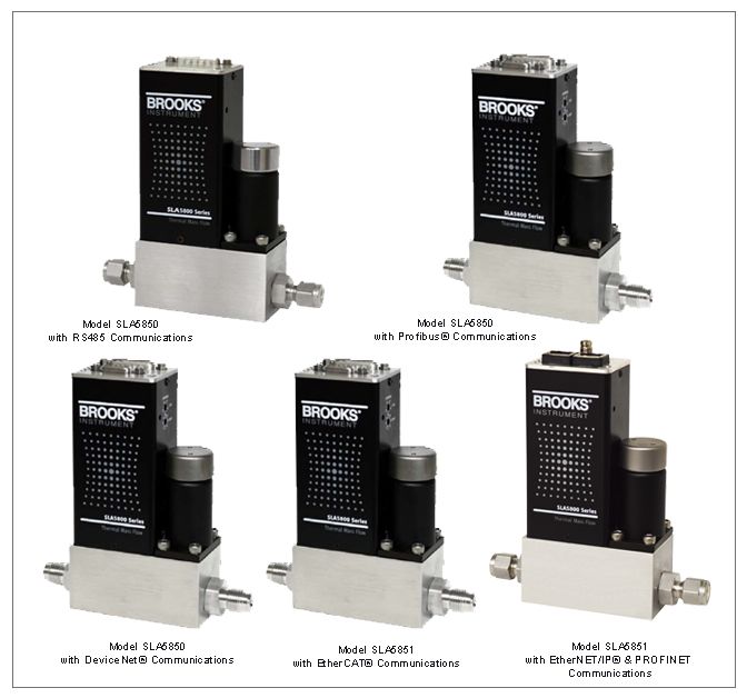
Thank you for purchasing a Brooks Instrument mass flow device. This
manual is an installation and operation manual for your instrument. If you
have purchased a Brooks® Digital Mass Flow Product with RS485,
DeviceNet®, Profibus®, EtherCAT® , EtherNet IPTM or PROFINET
communicatons, a separate supplemental manual is also available as
part of the operating documentation.
Brooks Instrument mass flow measurement instruments are designed for
accurately measuring (MFMs) and rapidly controlling (MFCs) flows of
gases. This instruction manual is intended to provide the user with all the
information necessary to install, operate and maintain these devices. This
manual is organized into the following sections.
Section 1 Introduction
Section 2 Installation
Section 3 Operation
Section 4 Maintenance
Section A Essential Instructions
Back Cover Warranty, Local Sales/Service Contact Information
It is recommended that this manual be read in its entirety before attempting
to operate or repair these devices.
1
Section 1 Introduction
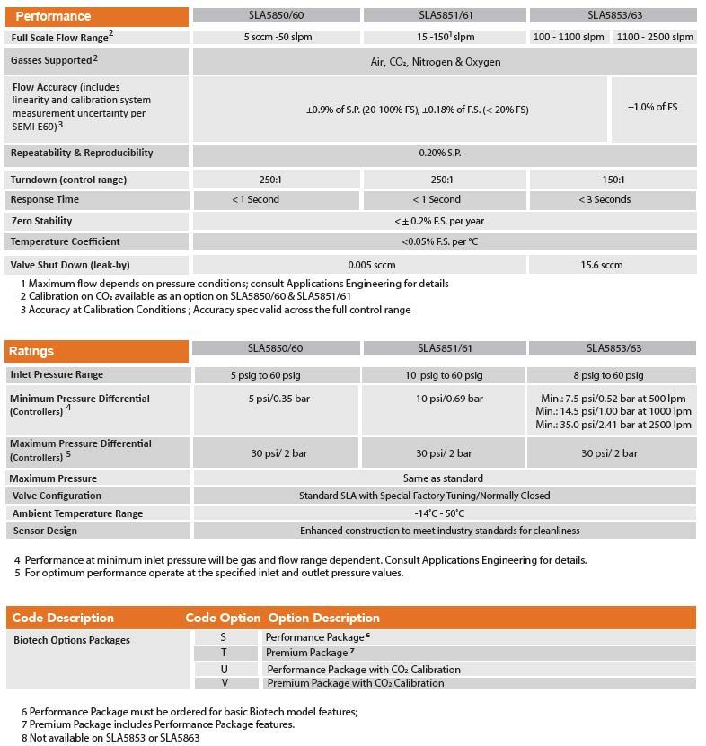
Specifications (Reference Tables 1-1 and 1-2)
2Section 1 Introduction
Table 1 SLA5800 Series Standard Specifications
3Section 1 Introduction
Table 1-2 SLA5800 Series Biotech Specifications
4Section 1 Introduction
Table 1-3 Electrical Specifications
5Section 1 Introduction
Table 1-4 SLA5800 Series Certifications
Note:
1) Not all certifications are available for all SLA5800 specifications and configurations.
Please contact Brooks Customer
ATEX/IECEx Specific conditions of use
1. The equipment shall only be used in an area of not more than pollution degree 2, as defined in
EN/IEC 60664-1.
2. The modules shall be installed in a suitable enclosure providing a degree of protection of
at least IP54 according to IEC/EN 60079-7, taking into account the environmental conditions
under which the equipment will be used.
3. Provisions shall be made to prevent the rated voltage from being exceeded by transient
disturbances of more than 140%.
UL Conditions of Acceptability
1. These devices are to be used within their ratings.
2. These devices are to be mounted in a suitable enclosure in the end product rated not less than IP40.
3. The wiring terminals are suitable for field wiring.
4. The suitability of the wiring method is to be determined in the end-use application.
5. These devices are intended to be powered by a class 2 power source.
6. These devices were evaluated for use in a maximum ambient temperature of 65ºC.
Note: PROFINET Communications is available only with CE Certifcation.
6Section 1 Introduction
中国RoHS声明表
China RoHS Declaration Table*
Product Family: SLA5800 Series Pressure Controllers and Thermal Mass Flow Meters & Controllers
Product Model: (Analog, RS485 , DeviceNet™, Profibus, Ethercat, Ethernet/IP™)
SLA5810 and SLA5820 Pressure Controller SLA5840 Remote Transducer Pressure Controller
SLA5850, SLA5851, and SLA5853 Thermal Mass Controllers
SLA5860, SLA5861 and SLA5863 Thermal Mass Meters
Table 1: Names and Contents of Toxic or Hazardous Substances or Elements
表 1: 有毒有害物质或元素的名称及含量
环保使用期限
EFUP
有毒有害物质或元素
Toxic or hazardous Substances and Elements
部件名称 铅 汞 镉 六价铬 多溴联苯 多溴二苯醚
Part Name Lead Mercury Cadmium Hexavalent Chromium Polybrominated Polybrominated diphenyl ethers
(Pb) (Hg) (Cd) (Cr (VI)) biphenyls (PBB) (PBDE)
印刷电路组件
Printed Circuit X O O O O O
Assemblies
电缆和连接器
Cables and X O O O O O
Connectors
壳体
Housing O O O O O O
6 机械零件
Mechanical O O O O O O
Parts
O 表示该有毒有害物质在该部件所有均质材料中的含量均在 SJ/T11363-2006 规定的限量要求以下
O: Indicates that this toxic or hazardous substance contained in all of the homogeneous materials for this part is below the limit
requirement in SJ/T11363-2006.
X 表示该有毒有害物质至少在该部件的某一均质材料中的含量超出 SJ/T11363-2006 规定的限量要求。
X: Indicates that this toxic or hazardous substance contained in at least one of the homogeneous materials used for this part is above the
limit requirement in SJ/T11363-2006
环保期限(EFUP )的产品及其部件是每个列出的符号,除非另有标明。使用期限只适用于产品在产品手册中规定的条件下工作
The Environmentally Friendly Period (EFUP) for the product and its parts are per the symbol listed, unless otherwise marked. Use Period
is valid only when the product is operated under the conditions defined in the product manual.
*Certain special SLA’s have Chine RoHS labels, so this table applies to those cases only
7Section 1 Introduction
Reference Conditions
Due to effects of pressure and temperature on the compressibility of
gases, specific reference conditions must be used when reporting
volumetric flow rates in mass flow terms. For example, the unit of measure
SCCM (standard cubic centimeters per minute) refers to a volumetric gas
flow at a standard reference condition, NOT the actual volumetric gas flow
at the actual operating pressure and temperature. The key point is that the
MASS FLOW of the gas is fixed, but the reference volumetric flow can be
reported differently based upon the standard reference condition used in
the calculation.
Throughout the world, there are differences in terminology when describing
reference conditions for gases. The words “normal conditions” and
“standard conditions” are sometimes used interchangeably to describe the
reference STP (Standard Temperature and Pressure) for gases. Further
note that temperature and pressure values for standard or normal
reference conditions vary in countries and industries worldwide. For
example, the Semiconductor Equipment Manufacturing Industry (SEMI)
defines standard temperature and pressure conditions as 273.15 K (0 °C)
and 101,325 Pa (760 torr). The main concern is that no matter what words
are used for descriptive purposes, a gas mass flow rate must have a
defined standard pressure and temperature reference condition when
performing a volumetric conversion.
Biotech Options Packages
The SLA58XX mass flow controllers and meters are available with two
biotech options packages - Performance and Premium - that include a
number of enhanced features designed for the biotech industry and for
bioreactors/fermenters specifically. The specifications are shown in Table
1-2. Instructions for changing between the four available gasses are
included in Section 3 on page 33 of this manual.
PC-based Support Tools
Brooks Instrument offers a variety of PC-based process control and service
tools to meet the needs of our customers. Smart Interface may be used with
any unit supporting RS485 S-Protocol in a multidrop configuration, thus
allowing users to control and monitor their Brooks devices. The Brooks
Expert Support Tool (BEST) may be used to monitor, diagnose, tune and
calibrate Brooks devices equipped with DeviceNet communications. The
Brooks Expert Support Tool interfaces with Brooks products via a special
service port.
8Section 1 Introduction
Figure 1-1 General Wiring
Fast Response Performance
The curves in Figure 1-2 depict the MFC output signal and actual
transitional flow to steady-state when gas flow enters into process
chamber, under a step response command condition.
Brooks devices also feature adaptive (optimized) PID control, including fast
response. and linear ramp-up and/or ramp-down control characteristics.
Calibration Selection
Select one of 6 calibrations via Brooks Expert Support Tool (BEST) or
digital signal (See communications protocol for your digital coms). Analog
devices can be switched via voltage signals to Pin 11 & 8 on Firmware
Version 1.18 & newer.
Selectable Soft Start
Processes requiring injection of gases can be adversely affected by
excessive initial gas flow. This abrupt injection of gas can result in process
damage from explosion or initial pressure impact. These problems are
virtually eliminated with the soft start feature.
9Section 1 Introduction
Linear ramp-up or ramp-up/down (Figure 1-3) set by user via software
tools or digital commands.
Linear ramp-up/ramp-down is adjustable at 200% per second down to
0.5% per second setpoint change.
Figure 1-2 Response Performance of Brooks Digital MFC
Figure 1-3 Linear Ramp-up and/or Ramp-down from 200% Per Second Down to 0.5 % Per Second Setpoint Change
10Section 1 Introduction
Function PIN
Setpoint: Common Input (-) 1
Flow Signal: 0(1) -5 Vdc, 0-10 Vdc (Option), Output (+) 2
TTL Alarm: Open collector, Output (+) 3
Flow Signal: 0(4)-20 mA, Output (+) 4
Power Supply: +13.5 Vdc to +27 Vdc(+) 5
Not Connected 6
Setpoint: 0(4)-20 mA, Input (+) 7
Setpoint: 0(1)-5 Vdc, 0-10 Vdc, Input (+) 8
Power Supply: Common (-) 9
Flow Signal: Common, Output, (-) 10
Not Connected 11
Valve Override: Input 12
Auxilliary: RT Input, 0-5 Vdc, 0-10 Vdc, Input (+) 13
RS-485: Common B (-) 14
RS-485: Common A (+) 15
Note: Aux Input is used for Remote
Transducer Pressure Controllers only.
Figure 1-4 SLA5800 Series RS485 15-Pin Analog Connector and Pinouts
RS485 Communications
The Brooks Digital Series is equipped with RS485 communication
capability. Refer to Figure 1-4 (Analog I/O pin connections), that enables
the device to communicate via a personal computer for process control.
Baud rate selections for the Brooks Digital Series related to RS485 are:
1200, 2400, 4800, 9600, 19200 and 38400 baud and can be selected via
the Brooks Expert Support Tool (BEST) .
The RS485 is essentially a multidrop connection. It allows a maximum of
32 devices to be connected to a computer system. Personal computers are
not equipped with RS485 ports as standard. An RS232/USB to RS485
converter or RS485 interface board is therefore required to connect an
RS485 network to a standard personal computer. The RS485 bus, a daisy
chain network, meaning that the wires are connected at the units as in Figure 1-1.
11Section 1 Introduction
Note: Aux Input is used for Remote
Transducer Pressure Controllers only.
Figure 1-5 SLA5800 Series Profibus Connections and Pinouts
Profibus Communications
The Brooks SLA5800 is now equipped to support the Profibus
communication protocol. Profibus is a fieldbus-based automation
standard of Profibus and Profinet International (PI). Via a single bus
cable, Profibus links controller or control systems with decentralized field
devices (sensors and actuators) on the field level and also enables
consistent data exchange with higher ranking communication systems. A
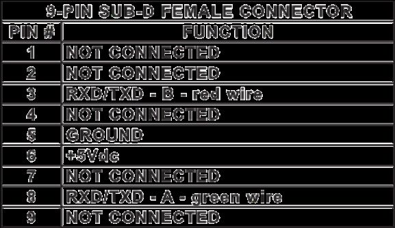
9-pin sub-D connector is included on every device and is galvanic
isolated from the main electronics as defined by the EN 50170 Profibus
standard to allow easy network connection separate from the main
connector. The main 15-pin sub-D connector or termination board is still
needed for the power supply, but also allows for the standard analog I/O
signals, analog valve override, and (open-collector) alarm signaling to be
used separate from the network connection.
The communication electronics allows for automatic baud rate detection
ranging from 9600 baud to 12 Mbaud, thus making the need for any
hardware baud rate selection methods not required. For selecting the
device address, which must be unique on the network, two rotary
switches are provided. This allows a user to easily select any address
number ranging from 0 to 126. This can provide fast device replacement
without complex network configurations. The Profibus-DP piggyback
board is equipped with a zero command pushbutton, allowing the user to
give a manual command to the device to (re)balance the flow sensor
electronics. This command can also be issued through the protocol.
The Profibus-DP communication option supports the following message types:
• Cyclic data exchange (Write/Read data).
• Read inputs (e.g. status, flow, temperature, totalizer, etc.).
• Read outputs (e.g. commands, setpoint).
• Global control commands (e.g. fail safe, sync).
• Get configuration (i.e. read number of I/O bytes and composition).
• Read diagnostics information (i.e. get error and alarm status).
• Set parameters (i.e. select gas number, engineering units, I/O configuration
• Set parameters (i.e. select gas number, engineering units, I/O
configuration etc.).
• Check configuration (i.e. check I/O composition).
12Section 1 Introduction
Figure 1-5.5 EtherNet/IP™& PROFINET M8 Power Connection and Pinnouts
EtherNet/IPTM & PROFINET Communications
The SLA5800 Series is now available with the state-of-the-art EtherNet/IPTM
communications interface. Please refer to the supplemental EtherNet/IPTM
manual for more description of the benefits of Brooks’ implementation of the
communications platform.
The available physical interfaces on the EtherNet/IPTM & PROFINET devices
are listed below:
• 5 pin M8 threaded male connector for power and Analog l/O, indicated by
pwr”.
• ln and Out ports with RJ-45 connectors with industry standard pin outs,
labelled “1” and “2”.
• 2.5mm female jack for RS485 diagnostic port indicated by “DlAG”
Embedded Browser Interface:
• Network address is 192.168.1.100 (EtherNET & PROFINET)
• EtherNET/IP: Network configuration is DHCP.
• PROFINET: The default name is “sla-mfc”
13Section 1 Introduction
Figure 1-6 SLA5800 Series DeviceNet Connection and Pinouts
DEVICENET BUS
5 PIN MALE M12 CONNECTOR
M12 X 1.0 OUTSIDE THREAD
DeviceNet Communications
The SLA5800 Series is also available with DeviceNetTM communication
capability. DeviceNet is an open digital protocol capable of high speeds
and easy system connectivity. Brooks Instrument has several of its
devices available on this popular networking standard, and is a member of
ODVATM (Open DeviceNet Vendors Association), the governing standard
body for DeviceNet.
DeviceNet is similar to the RS485 standard in that it is a multi-drop connection
that allows a maximum of 64 devices to be connected on the same network.
Baud rate selections for DeviceNet products are 125K, 250K and 500K and
can be selected via a rate switch mounted on the device.
The DeviceNet communication link also provides access to many of the
Brooks SLAMf Digital Series functions for “control and monitor” operations,
including:
• Accurate setpoint adjustment and flow output measurement (including
units of measure selection)
• PID Settings (controller only)
• Valve Override (controller only)
• Calibration Gas Select
• Soft Start Control (controller only) 14Section 1 Introduction
Figure 1-7 SLA5800 Series EtherCAT Connection and Pinout
EtherCAT Communications
The SLA5800 Series is also available with EtherCAT
communication capability. Many applications of Flow
Controllers/Meters are moving to increase the use of
automation. Automation comes in many forms including
Ethernet based field buses. Digital communications from these
varied systems and the devices they measure and control, are
a very effective means of not only accomplishing more effective
and rapid system integration, but also providing greatly
improved system diagnostics and maintainability.
The available physical interfaces on the EtherCAT device are listed below:
• 5 pin M8 threaded male connector for power and Analog l/O, indicated by “pwr”.
• ln and Out ports with RJ-45 connectors.
• 2.5mm female jack for RS485 diagnostic port indicated by “DlAG” (refer
to the SLA 5800 Series installation and operation manual for more details)
The EtherCAT communication option supports the following message types:
• Cyclic data exchange (Read/Write data)
• Read lnputs (e.g. status, flow, temperature, actuator drive value, etc.)
• Read Outputs (e.g. commands, setpoint, actuator override, etc.)
• Read Diagnostics information (warning & alarm status)
• Check Device configuration
• Calibration due status
15
• Hardware/Software versions etc.Section 1 Introduction
Figure 1-8 SLA5850/SLA5851/SLA5860/SLA5861 Dimensions
16Section 1 Introduction
Figure 1-9 SLA5850/SLA5851/SLA5860/SLA5861 Dimensions
17Section 2 Installation
Section 2: Installation
This section provides installation instructions for the Brooks® Digital MFC's
and MFM's. Section 1, Figures 1-8 thru 1-17 show the dimensions and
electrical connections.
Receipt of Equipment
When the equipment is received, the outside packing case should be
checked for damage incurred during shipment. If the packing case is
damaged, the local carrier should be notified at once regarding his liability.
A report should be submitted to the nearest Brooks Instrument location
listed on the Global Service Network page on our website:
BrooksInstrument.com/GlobalSupportCenters
Remove the envelope containing the packing list. Carefully remove the
instrument from the packing case. Make sure spare parts are not discarded
with the packing materials. Inspect for damaged or missing parts.
Recommended Storage Practice
If intermediate or long-term storage of equipment is required, it is
recommended that the equipment be stored in accordance with the
following:
a. Within the original shipping container.
b. Stored in a sheltered area, preferably a warm, dry, heated warehouse.
c. 32°C (90°F) maximum, 7°C (45°F) minimum.
d. Relative humidity 45% nominal, 60% maximum, 25% minimum.
Upon removal from storage a visual inspection should be
conducted to verify the condition of equipment is "as received".
Return Shipment
Prior to returning any instrument to the factory for any reason, visit our
website for instructions on how to obtain a Return Materials Authorization
Number (RMA #) and complete a Decontamination Statement to
accompany it: BrooksInstrument.com/Service. All instruments returned to
Brooks also require a Material Safety Data Sheet (MSDS) for the fluid(s)
used in the instrument. Failure to provide this information will delay
processing of the instrument.
Instrument must have been purged in accordance with the following:
18Section 2 Installation
Transit Precautions
To safeguard against damage during transit, transport the instrument to the
installation site in the same container used for transportation from the
factory if circumstances permit.
Removal from Storage
Upon removal from storage, a visual inspection should be conducted to
verify the condition of the equipment is “as received.” If the equipment has
been in storage in conditions in excess of those recommended
(See Section 2-3), the device should be subjected to a pneumatic pressure
test in accordance with applicable vessel codes.
Gas Connections
Prior to installation ensure all piping is clean and free from obstructions.
Install piping in such a manner that permits easy access to the instrument
if removal becomes necessary.
In-Line Filter
Unless an integrated (internal) filter is already installed, it is recommended
that an in-line filter be installed upstream from the mass flow controller or
meter to prevent the possibility of any foreign material entering the flow
sensor or control valve MFC. The filtering element should be replaced
periodically or ultrasonically cleaned.
Table 2-1 Recommended Filter Size
Models Maximum Flow Rate Recommended Filter
SLA5850/60 100 ccm 2 micron
SLA5850/60 500 ccm 2 micron
SLA5850/60 1 to 5 lpm 10 micron
SLA5850/60 10 to 50 lpm 40 micron
SLA5851/61 15 to 100 lpm 40 micron
SLA5853/63 > 100 lpm Consult factory
Note: Brooks provides many filter options. For those not listed here, please contact factory.
19Section 2 Installation
Installation
Recommended installation procedures:
e. The Brooks Digital MFC or MFM should be located in a clean,
dry atmosphere relatively free from shock and vibration.
f. Leave sufficient room for access to Self-zero function push-button.
g. Install in such a manner that permits easy removal if the instrument
requires servicing.
h. The Brooks Digital MFC or MFM can be installed in any position.
However, mounting in orientations other than the original factory
calibration (see calibration data sheet supplied with the instrument)
can result in aSection 2 Installation
Special considerations for high pressure installations
The SLA-Series mass flow devices are capable of operation in high
pressure applications. To ensure proper operation the user must be aware
of the pressure conditions specified for the device. Inlet and outlet
pressure conditions can be found on the device label and calibration sheet.
The device was sized and tuned to operate at the specified pressure
conditions. If the differential pressure during start up exceeds the specified
differential pressure, hydraulic forces may keep the valve from opening
and/or controlling properly. In these applications it is important to bring the
pressure up in a controlled manner.
One method to assure successful startups is set a 100% setpoint
command or valve override open command and then gently ramp the
pressure up to operating (specified) conditions. This will allow you to bring
your process pressure up to normal operating conditions where the SLA
mass flow controller will function as specified.
Another method is to utilize a bypass valve to allow pressure around the
device while ramping up the back pressure to normal operating conditions.
Special considerations to be taken when installing the SLA5853 MFC:
The Model SLA5853 has a valve design that is different from the standard
low flow Brooks TMFC's. The SLA5853 consists of a dual stage, pilot
operated valve. The pilot valve (located on the top of the MFC) controls a
differential pressure across the main valve which, in turn controls the flow
through the device. The main valve is a pressure operated valve that
utilizes a bellows spring and diaphragm to control flow. This bellows and
diaphragm assembly can be susceptible to damage by pressure spikes or
surges. For this reason, it is recommended that process line startups are
handled with care.
The bellows spring is offered in two levels. A low force for low differential
pressures (Delta P < 30psig), and a high force (delta P >30 andSection 2 Installation
The main point is to not instantly open a ball valve and allow a high upstream
pressure or high back pressure surge into the SLA5853 main valve.
Proper process line venting is also important. If operating at pressures
greater than 50 psig, be sure to perform a controlled pressure release from
inlet and back pressure simultaneously in order to prevent bellows damage
from excesssive back pressure.
Following careful startup and venting procedures will contribute to a long
problem free life of your SLA5853 controller.
Stable Operating Conditions:
As stated above, the SLA5853 model utilizes a pressure operated main valve.
Valve performance is dependant on stable system pressures. Oscillating or
unstable upstream or downstream pressures are likely to cause the device
flow control to become unstable. For the best performance, it is important to
create a stable pressure environment by utilizing quality inlet and back
pressure regulators in your process design. In many cases, the addition of a
back pressure regulator will isolate the SLA5853 from the unstable
downstream pressures inherent in many process designs.
All thermal mass flow controllers are factory tested with stable and equal
ambient and process temperatures. If the process temperature does not
equal the ambient temperature, the bypass ratio/accuracy will be affected.
When a hot or cold process fluid is being measured, ensure that the piping
system is designed to allow the gas temperature to equalize with the flow
controller ambient temperature.
For more information, please contact the Brooks Technical Service group.
Special considerations to be taken when using Sanitary Fittings:
The maximum recommended product rating of 500 psi is based on published
product specifications of commonly available sanitary clamps. Brooks does not
supply sanitary clamps with the products. Customers shall select the appropriate
sanitary clamps and follow the manufacturers installation instructions to achieve
the needed pressure ratings
2
2Section 2 Installation
Electrical Interface
The setpoint signal is supplied as a 0(1) to 5 Vdc, 0 to 10 Vdc or 0(4)-20 mA
analog signal. All signals are supplied via the 15-pin D-Connector. For an
analog unit the minimum set of connections which must be made to the MFC
and MFM includes +13.5 - 27 Vdc, supply common, and a setpoint signal.
The Brooks Digital electrical interface is designed to facilitate
low-loss, quiet signal connections. Separate returns (commons) are
supplied for the analog setpoint, analog flow signal, and the power supply.
These commons are electrically connected together on the PC board.
Analog I/O Versions
• Signal Common
• Signal Output (Voltage or Current)
• +13.5 - 27 Vdc Supply
• Setpoint Input (Voltage or Current)
• Setpoint Common
• Supply Common
• Chassis Ground (via unit body)
Refer to Figures 2-1, 2-2, 2-3, 2-4 and 2-5 for pin connections and
electrical I/O connections.
(The Brook’s MFC acts as a current sink to a setpoint input signal. The 0/4-20 mA
setpoint signal should be “driven” into the MFC input by a controlled current source.
Reference Brook’s device specifications for the setpoint input impedance.)
(The Brook’s MFC acts as the current source when providing a 0/4-20 mA output
signal to the load. The output signal is “driven” by the MFC into the customer
load. Reference Brook’s device specifications for maximum load capacity.)
2
3Section 2 Installation
Figure 2-1 RS485 D-Connector Shielded Cable Hookup Diagram, Voltage I/O Version
24Section 2 Installation
Figure 2-2 Recommended I/O Wiring Configuration for Current Signals (Non-Isolated Power Supply)
Figure 2-3 Recommended I/O Wiring Configuration for Current Signals (Isolated Power Supply)
25Section 2 Installation
Figure 2-4 RS485 Multidrop Interconnection TMFs and PC
The RS485 is a multidrop connection and allows a maximum of 32 devices
to be connected to a computer system. Personal computers are not
equipped with RS485 ports as standard. An RS232 to RS485 converter or
RS485 interface board is therefore required to connect an RS485 to a
standard PC. Figure 2-4 is an interconnection diagram showing two TMFs
linked to a PC, via RS485 and RS485 to RS232 converter. The RS485 bus,
a daisy-chain network, meaning that the wires are connected at the units
as in Figure 2-4.
Protective Earth (PE) Connections:
DeviceNet™: The shield of the cable does not directly short to the device
chassis. In order to achieve proper EMC compliance, the device
conductive chassis shall be connected to protective earth (PE). The
connection can be made via the 8-32 threaded connection on the flow
body of the meter/controller.
Ethernet/IP™& PROFINET: The shields of the RJ45 cables do not directly
short to the device chassis, per Industry guidelines for an “active device.”
The shield of the power cable does directly connect to the device chassis.
In order to achieve proper EMC compliance, it is recommended to connect
the device conductive to protective earth (PE). The connection can be
26Section 2 Installation
made via the 8-32 threaded connection on the flow body of the
meter/controller.
Other device types: The shields of the power and I/O cables directly
connect to the device chassis. In order to achieve proper EMC
compliance, it is recommended to connect the device conductive to
protective earth (PE). The connection can be made via the 8-32 threaded
connection on the flow body of the meter/controller.
27Section 2 Installation
Operation Check Procedure (Analog I/O)
j. Mount the MFC/MFM in its final orientation.
k. Apply power to the MFC/MFM and allow approximately 45 minutes for
the instrument to completely warm up and stabilize its temperature.
l. Do NOT supply gas to the MFC/MFM. Ensure that the differential
pressure across the MFC/MFM is zero.
m. Apply a setpoint of:
0.000 Vdc ± 10 mV (0 - 5 Vdc or 0 - 10 Vdc setpoint)
1.000 Vdc ± 10 mV (1 - 5 Vdc setpoint)
0.000 mA ± 100 µA (0 - 20 mA setpoint)
4.000 mA ± 100 µA (4 - 20 mA setpoint)
n. If the zero exceeds one of these limits, follow the re-zeroing procedure
in Section 3-4. The analog output signal should be:
0.000 Vdc ± 10 mV (0 - 5 Vdc or 0 - 10 Vdc output)
1.000 Vdc ± 10 mV (1 - 5 Vdc output)
0.000 mA ± 40 µA (0 - 20 mA output)
4.000 mA ± 40 µA (4 - 20 mA output)
o. Turn on the gas supply. A positive flow signal may be present due to
slight valve leak-thru (MFC only).
p. Supply a setpoint signal between:
0 to 5 Vdc (0 - 5 Vdc setpoint) or 0 to 10 Vdc (0 - 10 Vdc setpoint)
1 to 5 Vdc (1 - 5 Vdc setpoint)
0 to 20 mA (0 - 20 mA setpoint)
4 to 20 mA (4 - 20 mA setpoint)
q. Check the analog output signal. The output signal should match the
setpoint signal in accordance with the accuracy specifications provided
in Section 1-4 of this document.
r. If flow output signal does not match the setpoint, and pressure settings
are correct, this could indicate a problem in the MFC. A secondary
issue could be the gas type. When checking with a surrogate gas,
ensure that there is enough pressure to the MFC in order to flow the
correct amount of the surrogate gas.
Example:
Checking an MFC calibrated for 100 ccm SF6 (sulfur hexafluoride).
The sensor factor N2 (nitrogen) is 0.27, therefore the eqivalent N2
needed is 100/0.27 = 370.4 ccm. This may require a pressure
increase to make this flow rate.
28Section 2 Installation
Operation Check Procedure (Digital I/O)
s. Mount the MFC/MFM in its final orientation.
t. Apply power to the MFC/MFM and allow approximately 45 minutes for
the instrument to completely warm up and stabilize its temperature.
u. Turn on the gas supply. A positive flow signal may be present due to
slight valve leak-thru (MFC only).
v. Provide the proper UOM setpoint between 20% and 100% FS to the
MFC via the digital network controller.
w. Check the MFC Flow value. It should match the setpoint UOM. Value
within ± 0.2% FS in less than 10 seconds after setpoint change.
x. If flow output signal does not match the setpoint, and pressure settings
are correct, this could indicate a problem in the MFC. A secondary
issue could be the gas type. When checking with a surrogate gas,
ensure that there is enough pressure to the MFC in order to flow the
correct amount of the surrogate gas.
Example:
Checking an MFC calibrated for 100 ccm SF6 (sulfur hexafluoride).
The sensor factor N2 (nitrogen) is 0.27, therefore the equivalent N2
needed is 100/0.27 = 370.4 ccm. This may require a pressure increase
to make this flow rate.
Bus/Network (DeviceNet, Profibus, EtherCAT, EtherNET/IPTM, PROFINET)
Other problems that may occur in an operational checkout of a Bus/
Network MFC could be due to data mismatches of Input/Output I/O
assemblies. For proper communication over the Bus/Network network, the
MFC must be set up with the same I/O Assembly as the network master.
The Bus/Network specification defines Input and Output relative to the
network (i.e. the data being PRODUCED from the device (MFC) as an
INPUT into the network or the data is being CONSUMED by the device
(MFC) is an OUTPUT from the network).
NOTE: For additional EtherNET/IPTM, PROFINET, DeviceNet, Profibus,
or EtherCAT details, please see Brooks Supplemental Instruction
Manuals.
29Section 3 Operation
Section 3: Operation
Features
Note: Not all features are available on all instruments.
Brooks Instrument digital MFC/MFMs are full-featured devices that perform
much like traditional analog MFCs, but with improved accuracy, step response
and valve control. The analog interface matches that of Brooks' popular
analog MFCs so it can be retrofitted into tools using analog MFCs. Other
versions of the Delta Class can provide a variety of digital protocols.
SLA5800 Series Standard
A digital SLA5800 Series Standard MFC is capable of storing up to six
different gas pages. Each page (also) includes a calibration curve, PID
controller settings, valve performance data, and information about the
calibration conditions. The device can contain calibrations for different gases
or for the same gas at multiple conditions (pressures, full scale flow rates).
Calibrations will appear in the calibration table in the same order as they
appeared on the order, unless otherwise specified. The first listed gas will
appear as calibration #1, the second as calibration #2 and so on. Note that
unless specified otherwise on the order any unit containing a single calibration
will have that calibration stored s calibration #1.
The EtherNET/IP™, DeviceNet, Profibus, EtherCAT and RS485 supplemental
manuals describe further details on specific communication features.
SLA5800 Series Biotech
The SLA5800 Series Biotech Devices ships standard with the 4 key
BioPhamracuetical industry gasses: Air, N2, CO2 and O2. These are included
in the standard Performance Package option. The device is sized for the
specific gas chosen by the user at time of order, that is the configuration gas.
The calibration curves are obtained by use of N2 as a surrogate gas. If actual
CO2 gas is chosen, as an extra cost option (for SLA58X0 and SLA58X1 only),
then the device is calibrated on CO2 and N2 surrogate for the remaining
gasses.
Each gas has a “page” that includes a calibration curve, PID controller
settings, valve performance data, and information about the calibration
conditions. The active gas page will be the Configuration Gas, which will be
listed on ordering documents, and the top label of the controller. The other
three gas ranges will also be listed on the controller label.
The operator can change the active gas “page” either through the Brooks
Expert Support Tool (BEST) software available at BrooksInstrument.com or
through the digital communications protocols if the device is so equipped.
3
0Section 3 Operation
When using BEST, the pages will appear in the calibration table in the same
order as noted above: Air will appear as calibration #1, N2 as calibration #2
and so on. For more detailed instructions on how to activate gas pages using
BEST, please see the Cal Pages and Flow Cal Pages section of the
Installation and Operations manual for BEST, also available at
BrooksInstrument.com.
The EtherNET/IP™, DeviceNet, Profibus, EtherCAT and RS485 supplemental
manuals describe further details on how to change gases for specific
communication features.
Analog I/O Mode of Operation
The following paragraphs describe the basic features of the Brooks Digital
Series Mass Flow Meters/Controllers.
Functional Description
The analog interface may include any of the following I/O options as
specified by the user:
0 - 5 Vdc setpoint, 0 - 5 Vdc flow output
1 - 5 Vdc setpoint, 1 - 5 Vdc flow Output
0 - 20 mA setpoint, 0 - 20 mA flow output
4 - 20 mA setpoint, 4 - 20 mA flow output
0 - 10 Vdc setpoint, 0 - 10 Vdc flow output
Also included is the Valve Override input pin. All analog signals available
are on the 15 pin D-Connector. (See Fig. 2-1 for connections). The
contents of the ten calibrations are determined from the customer order.
Only those calibrations ordered will be available in the instrument. Unless
otherwise specified, a Brooks Digital MFC/MFM ordered with only one
calibration will have that calibration stored in calibration #1.
Before operating the MFC/MFM, apply power and warm-up the instrument
for approximately 45 minutes. After warm-up, apply gas pressure then
proceed by following the instructions in the following sections.
Analog I/O Setpoint (MFC Only)
This input allows the user to establish the MFC setpoint,. Several input
types are available as follows:
Setpoint Signal Type Full Scale Minimum Signal Maximum Signal
0 to 5 Vdc 5 Vdc 0V 5.5 Vdc = 110%
1 to 5 Vdc 5 Vdc 1V 5.5 Vdc = 111%
0 to 20 mA 20 mA 0 mA 22 mA = 110%
4 to 20 mA 20 mA 4 mA 22 mA = 111%
0 to 10 Vdc 10 Vdc 0V 11 Vdc = 110%
31Section 3 Operation
Analog I/O Flow Signal
This output is used to indicate the flow signal. The minimum flow output is
0 flow.
Several flow signal types are available:
Analog I/O Type Full Scale Minimum Signal Maximum Signal
0 to 5 Vdc 5 Vdc -0.5 V 5.5 Vdc = 110%
1 to 5 Vdc 5 Vdc 0.5 V 5.5 Vdc = 111%
0 to 20 mA 20 mA 0 mA 22 mA = 110%
4 to 20 mA 20 mA 3.8 mA 22 mA = 111%
0 to 10 Vdc 10 Vdc 0V 11 Vdc = 110%
Valve Override (MFC Only)
Valve Override Input allows the valve to be forced to its most closed state
or its most open state, regardless of setpoint. If this input is not electrically
connected, the MFC will operate according to the current values of the
other MFC inputs. If this input is held at 0 Vdc or -15 Vdc the valve will be
forced to its most closed state. If this input is held at +5 Vdc or greater
(max = 24 Vdc), the the valve will be forced to its open state.
Zeroing the MFC
It may be desirable to re-zero the flow sensor if it is operated at its
temperature extremes or if it is positioned in an attitude other than that
specified on the customer order.
To zero the device’s sensor:
1. Allow the device to be powered on for 45 minutes so that it achieves its
operating temperature.
2. Close the downstream shutoff valve.
The device should be full of process gas with no pressure
differential.
3. Wait at least 30 seconds for the flow signal to drop to zero.
4. Using the device’s Zero pushbutton, zero the device:
- press the pushbutton until the device’s Status LED flashes red, then
release the pushbutton. A successful zeroing
operation is indicated by the Status LED being a steady green.
The zeroing operation can take up to 10 seconds to complete.
The zero button can be disabled by setting DmOverride04=1. When
DmOverride04=0 the device should zero properly.
Note: Before zeroing the instrument, zero pressure differential MUST be established
across the device. If there is pressure across the instrument during the zero process,
any detected flow through the sensor will be misinterpreted as the zero flow reading.
This will result in calibration inaccuracy during normal operation.
Once zero differential pressure is established and verified, press the recessed,
momentary push-button (zero button) located on the side of the device
(See Figure 3-2) to start the zero function.
32Section 3 Operation
Zero Button
Figure 3-1 Externally Accessible Adjustment (Zero Button) for all Meters/Controllers.
RS485 Communications Features (Analog versions only)
Digital communication, designed to emulate the Brooks S-series
"S-protocol" or pseudo-HART communications is available on the Brooks
Digital Series via RS485. This form of multi-drop capable communication
provides access to many of the Brooks Digital Series functions for "control
and monitor" operations, including:
• Accurate setpoint adjustment flow output measurement
(including units of measure selection)
• Valve Override (controller only)
• Flow Totalizer (note that the Current totalizer value is written to EEPROM every 2
hours. After power a power interruption within 2 hours, the totalizer will be
restarted from previously stored value)
• Alarm status and settings
• Soft Start Control (controller only)
RS485 equipped units support the following baud rates. Please specify the
desired baud rate when ordering (default is 19200 baud). Alternately, baud
rate may be changed using the Brooks Expert Support Tool (BEST).
Baud Rates: 1200, 2400, 4800, 9600, 19200 and 38400
Reference the Brooks document "Supplemental Manual for RS485
Communications for Brooks® MFCs/MFMs, for SLA5800/SLAMf Revsion B
Series" (X-DPT-RS485-SLA5800-SLAMf-Series-RevB-MFC-eng) for more
details regarding the capabilities of this communication interface.
33Section 3 Operation
EtherNet/IP™ & PROFINET Communication Features
Brooks lnstrument now introduces the state-of-the-art EtherNet/IP™ & PROFINET
communications interface on its SLA Series platform.
Please refer to the supplemental EtherNet/IP™ & PROFINET manuals for more
description of the benefits of Brooks’ implementation of the communications platform.
The available physical interfaces on the EtherNet/IP™ & PROFINET device are listed
below:
• 5 pin M8 threaded male connector for power and Analog I/O, indicated by pwr.
• In and Out ports with RJ-45 connectors Labeled “1” and “2”.
• 2.5mm female jack for RS485 diagnostic port indicated by ‘DIAG’
Embedded Browser Interface:
• Network address is 192.168.1.100 (EtherNET & PROFINET)
• EtherNET/IP: Network configuration is DHCP.
• PROFINET: The default name is “sla-mfc”
DeviceNet Communications Features
The Brooks SLA5800 Digital Series is also available with DeviceNetTM
communication capability. DeviceNet is an open digital protocol capable of
high speeds and easy system connectivity. Brooks Instrument has several
of its devices available on this popular networking standard, and is a
member of ODVATM (Open DeviceNet Vendors Association), the governing
standard body for DeviceNet.
DeviceNet is similar to the RS485 standard in that it is a multi-drop connection
that allows a maximum of 64 devices to be connected on the same network.
Baud rate selections for DeviceNet products are 125K, 250K and 500K and
can be selected via MAC ID switches mounted on the device.
The DeviceNetcommunication link also provides access to many of the Brooks
SLA5800 Digital Series functions for “control and monitor” operations, including:
• Accurate setpoint adjustment and flow output measurement (including
units of measure selection)
• PID Settings (controller only)
• Valve Override (controller only)
• Calibration Gas Select
• Soft Start Control (controller only)
34Section 3 Operation
Profibus Communications Features
The communication electronics allows for automatic baud rate detection
ranging from 9600 baud to 12 Mbaud, thus making the need for any
hardware baud rate selection methods not required. For selecting the
device address, which must be unique on the network, two rotary switches
are provided. This allows a user to easily select any address number
ranging from 0 to 126. This can provide fast device replacement without
complex network configurations.
The Profibus-DP communication option supports the following message types:
• Cyclic data exchange (Write/Read data).
• Read inputs (e.g. status, flow, temperature, totalizer, etc.).
• Read outputs (e.g. commands, setpoint).
• Global control commands (e.g. fail safe, sync).
• Get configuration (i.e. read number of I/O bytes and composition).
• Read diagnostics information (i.e. get error and alarm status).
• Set parameters (i.e. select gas number, engineering units, I/O configuration
• Set parameters (i.e. select gas number, engineering units,
I/O configuration etc.).
• Check configuration (i.e. check I/O composition).
EtherCAT Communications Features
The SLA5800 Series is also available with the state-of-the-art
EtherCAT communications interface. Many applications of Flow
Controllers/Meters are moving to increase the use of
automation. Automation comes in many forms including
Ethernet based field buses. Digital communications from these
varied systems and the devices they measure and control, are
a very effective means of not only accomplishing more effective
and rapid system integration, but also providing greatly
improved system diagnostics and maintainability.
EtherCAT is an Ethernet based communication system and is known for its
high cycle time and cost efficient cabling and master application solutions.
The available physical interfaces on the EtherCAT device are listed below:
• 5 pin M8 threaded male connector for power and Analog l/O, indicated by “pwr”.
• ln and Out ports with RJ-45 connectors.
• 2.5mm female jack for RS485 diagnostic port indicated by “DlAG” (refer
to the SLA 5800 Series installation and operation manual for more details)
35You can also read