Glass level gauge, model LGG Schauglasanzeiger, Typ LGG - Wika
←
→
Page content transcription
If your browser does not render page correctly, please read the page content below
Operating instructions
                                     Betriebsanleitung

Glass level gauge, model LGG                                  EN

Schauglasanzeiger, Typ LGG                                    DE

            Glass level gauges, model LGG (examples)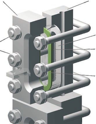
EN Operating instructions model LGG                               Page       3 - 28

DE Betriebsanleitung Typ LGG                                      Seite     29 - 54

   © 09/2016 WIKA Alexander Wiegand SE & Co. KG
   All rights reserved. / Alle Rechte vorbehalten.
   WIKA® and KSR® are registered trademarks in various countries.
   WIKA® and KSR® sind geschützte Marken in verschiedenen Ländern.

   Prior to starting any work, read the operating instructions!
   Keep for later use!
                                                                                        504323.05 05/2020 EN/DE

   Vor Beginn aller Arbeiten Betriebsanleitung lesen!
   Zum späteren Gebrauch aufbewahren!

    2                             Operating instructions glass level gauge, model LGG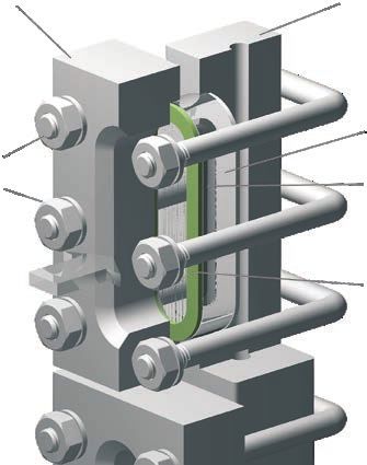
Contents

                          Contents                                                               EN

                          1. General information                                             4
                          2. Design and function                                             5
                          3. Safety                                                          8
                          4. Transport, packaging and storage                               12
                          5. Commissioning, operation                                       13
                          6. Faults                                                         18
                          7. Maintenance, repair and cleaning                               19
                          8. Dismounting, return and disposal                               24
                          9. Specifications                                                 25
                          10. Accessories                                                   26

                          Declarations of conformity can be found online at www.wika.com.
504323.05 05/2020 EN/DE

                          Operating instructions glass level gauge, model LGG                3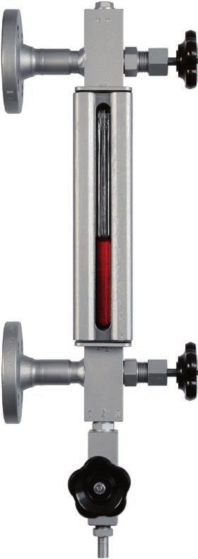
1. General information

     1. General information
     ■ The glass level gauges described in the operating instructions have
         been designed and manufactured using state-of-the-art technology.
EN
         All components are subject to stringent quality and environmental
         criteria during production. Our management systems are certified to
         ISO 9001.
     ■ These operating instructions contain important information on
         handling the instrument. Working safely requires that all safety
         instructions and work instructions are observed.
     ■ Observe the relevant local accident prevention regulations and
         general safety regulations for the instrument's range of use.
     ■ The operating instructions are part of the product and must be kept
         in the immediate vicinity of the instrument and readily accessible to
         skilled personnel at any time. Pass the operating instructions onto the
         next operator or owner of the instrument.
     ■ Skilled personnel must have carefully read and understood the
         operating instructions prior to beginning any work.
     ■ The general terms and conditions contained in the sales
         documentation shall apply.
     ■ Subject to technical modifications.

     ■ Further information:
         - Internet address:      www.wika.de / www.wika.com
         - Relevant data sheet:   LM 33.01
                                                                                    504323.05 05/2020 EN/DE

     4                        Operating instructions glass level gauge, model LGG
2. Design and function
2. Design and function
2.1 Functional description
The glass level gauges operate in accordance with the principle of
EN
communicating vessels. Through the built-in sight glasses, the filling level
of the liquid is directly visible.
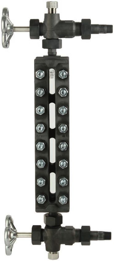
2.2 Construction of the glass level gauge
The body is the basic unit of the
Cover Body
glass level gauge and contains
the liquid channel. The sight glass
is secured to the cover via a flat
gasket and cushion using a screw U-bolt Flat gasket
connection. Valve heads (see Nut Glass
chapter 2.4) serve as shut-off
devices and connect the body with Cushion
the vessel.
2.3 Operating principle of the sight glass versions
LGG-R
Reflex glasses per DIN 8081
In the viewing direction, incident
light strikes the reflective grooves
of the sight glass plate and are
refracted into the liquid present.
With gases, the light is reflected. Viewing direction Viewing direction
Thus the filling level is visible as a Gaseous phase Liquid phase
darker column, the gaseous area
as a silvery column over it.
504323.05 05/2020 EN/DE
Operating instructions glass level gauge, model LGG 52. Design and function
LGG-T
Transparent glasses per DIN 7081
From the rear, incident light passes
through both sight glass plates with
EN the media between them. The fill
level is visible as a line (meniscus)
or directly due to the liquid itself.
Viewing direction
per DIN 7081
LGG-M
Refraction with mica shields
From the rear, incident light from
a lamp passes through both mica
shields with the medium between
them. The lamp and medium are
arranged at an angle. In the gaseous
phase, the light passes directly
through, with liquid, the light is
Viewing direction
refracted sideways. Thus the filling Refraction type with mica shields
level is visible as a black column,
the gaseous area as a light column
over it.
LGG-G
Transparent indicator with glass
tube
The filling level can be read directly
at the glass tube as a result of the
liquid column.
504323.05 05/2020 EN/DE
6 Operating instructions glass level gauge, model LGG2. Design and function
2.4 Valve heads
Valve body Head piece
EN
Valve heads isolate the vessel from the glass level gauge. They consist
of the valve body and the head piece. They are actuated by a valve
with quick closing lever or handwheel. In general, they are fitted with a
ball-check valve as a safety element.
2.5 Illustration of the ball-check valve principle
Situation in normal operation Ball-check valve on glass break Situation during commissioning
2.6 Scope of delivery
Cross-check scope of delivery with delivery note.
Mica shields are a natural product and thus streaks and
504323.05 05/2020 EN/DE
small inclusions are not any cause for complaint.
Operating instructions glass level gauge, model LGG 73. Safety
3. Safety
3.1 Explanation of symbols
EN DANGER!
... indicates a directly dangerous situation resulting in serious
injury or death, if not avoided.
WARNING!
... indicates a potentially dangerous situation that can result
in serious injury or death, if not avoided.
CAUTION!
... indicates a potentially dangerous situation that can result
in light injuries or damage to equipment or the environment,
if not avoided.
WARNING!
... indicates a potentially dangerous situation that can result
in burns, caused by hot surfaces or liquids, if not avoided.
Information
... points out useful tips, recommendations and information
for efficient and trouble-free operation.
3.2 Intended use
The glass level gauge is used for the continuous level indication of liquid
media in the industrial sector.
The scope of application is defined by the technical performance limits
and materials.
■ The media must not have any large contamination or coarse
504323.05 05/2020 EN/DE
particulates and must not have a tendency to adhere or crystallise.
■ Ensure that the wetted materials of the glass level gauge are
sufficiently resistant to the medium being monitored.
8 Operating instructions glass level gauge, model LGG3. Safety
■ The operating conditions specified in the operating instructions must
be observed.
■ The glass level gauges must not be exposed to heavy mechanical
strain (impact, bending, vibration).
EN
■ The technical specifications contained in these operating instructions
must be observed. Improper handling or operation of the instrument
outside of its technical specifications requires the instrument to be
taken out of service immediately and inspected by an authorised
WIKA service engineer.
The instrument has been designed and built solely for the intended use
described here, and may only be used accordingly.
The manufacturer shall not be liable for claims of any type based on
operation contrary to the intended use.
DANGER!
Work on containers involves the danger of intoxication and
suffocation. No work is allowed to be carried out unless by
taking suitable personal protective measures (e.g. respiratory
protection apparatus, protective outfit etc.).
WARNING!
Risk of burns!
At temperatures > 60 °C, a warning sign has to be attached
to flanges, tubes, case etc., warning explicitly of the danger
of burning and suitable protective measures must also be
taken.
504323.05 05/2020 EN/DE
Operating instructions glass level gauge, model LGG 93. Safety
3.3 Improper use
Improper use is defined as any application that exceeds the technical
performance limits or is not compatible with the materials.
EN WARNING!
Injuries through improper use
Improper use of the instrument can lead to hazardous
situations and injuries.
▶ Refrain from unauthorised modifications to the instrument.
WARNING!
The use of unprotected sight glasses in boiler systems with
aqueous media leads to increased glass erosion at high
temperatures and high pH values. The geometric changes to
the sight glass resulting from the erosion lead to risks in the
operational safety.
▶ At temperatures above 243 °C, use transparent glasses
with mica design.
Any use beyond or different to the intended use is considered as
improper use.
Do not use this instrument in safety or emergency stop devices.
3.4 Responsibility of the operator
The instrument is used in the industrial sector. The operator is therefore
responsible for legal obligations regarding safety at work.
The safety instructions within these operating instructions, as well as the
safety, accident prevention and environmental protection regulations for
the application area must be maintained.
To ensure safe working on the instrument, the operating company must
ensure the following:
504323.05 05/2020 EN/DE
■ The operating personnel are regularly instructed in all topics
regarding work safety, first aid and environmental protection
and know the operating instructions and in particular, the safety
instructions contained therein.
10 Operating instructions glass level gauge, model LGG3. Safety
■ The operating personnel have read the operating instructions and
taken note of the safety instructions contained therein.
■ The intended use for the application is complied with.
■ Following testing, improper use of the instrument is excluded.
EN
3.5 Personnel qualification
WARNING!
Risk of injury should qualification be insufficient
Improper handling can result in considerable injury and
damage to equipment.
▶ The activities described in these operating instructions
may only be carried out by skilled personnel who have the
qualifications described below.
Skilled personnel
Skilled personnel, authorised by the operator, are understood to
be personnel who, based on their technical training, knowledge
of measurement and control technology and on their experience
and knowledge of country-specific regulations, current standards
and directives, are capable of carrying out the work described and
independently recognising potential hazards.
3.6 Personal protective equipment
The personal protective equipment is designed to protect the skilled
personnel from hazards that could impair their safety or health during
work. When carrying out the various tasks on and with the instrument,
the skilled personnel must wear personal protective equipment.
Follow the instructions displayed in the work area regarding
personal protective equipment!
The requisite personal protective equipment must be provided by the
504323.05 05/2020 EN/DE
operating company.
Operating instructions glass level gauge, model LGG 113. Safety / 4. Transport, packaging and storage
3.7 Labelling, safety marks
Product label
EN
A division of the WIKA group
Model Permissible medium temperature range
Serial number PT: Test pressure
Measuring point number PS: Design pressure
Article number
Before mounting and commissioning the instrument, ensure
you read the operating instructions!
4. Transport, packaging and storage
4.1 Transport
Check the glass level gauges for any damage that may have been
caused by transport.
Obvious damage must be reported immediately.
4.2 Packaging and storage
Do not remove packaging until just before commissioning.
504323.05 05/2020 EN/DE
12 Operating instructions glass level gauge, model LGG5. Commissioning, operation
5. Commissioning, operation
■ Observe all instructions given on the shipment packaging for
removing the transportation safety devices.
EN
■ Remove the glass level gauge carefully from the packaging!
■ When unpacking, check all components for any external damage.
5.1 Mounting preparation
■ Remove the protection caps of the process connections.
■ Ensure that the sealing faces of the vessel or glass level gauge are
clean and do not show any mechanical damage.
■ Check the connection dimensions (centre-to-centre distance) and the
alignment of the process connections on the vessel.
5.2 Mounting of models LGG-R, LGG-T, LGG-M
■ Mount the glass level gauge vertically on the vessel.
■ Observe the torque values of screws specified in pipefitting work.
■ Install the glass level gauge without stresses.
■ In the selection of the mounting material (sealings, screws, washers
and nuts), take the process conditions into account. The suitability
of the sealing must be specified with regard to the medium and
its vapours. In addition, ensure it has corresponding corrosion
resistance.
■ For rotatable designs, the corresponding threaded connections must
be loosened by approx. 2 turns. Once the glass level gauge has been
aligned, tighten the threaded connection again to 25 Nm.
504323.05 05/2020 EN/DE
Operating instructions glass level gauge, model LGG 135. Commissioning, operation
■ Close valves and shut-off, drain and vent fittings
Valve with quick closing lever Valve with handwheel
Closing in a clockwise direction Closing in a clockwise direction
EN
■ Test the screw connections of the sight glass.
Tighten the screw connections with a torque spanner to the specified
values from the table. The sequence for the systematic tightening of
the screws is illustrated in the following sketch.
Tightening torques in Nm for covers and pressure plates
Size Material Max. allowed operating pressure
up to 100 bar > 100 bar
7/16 UNC A193 B7 35 -
A320 L7 35 -
A193 B8 45 -
Duplex 50 60
3/4 UNC A193 B7 80 -
A320 L7 80 120
A193 B8M - 120
M10 8.8 30 -
A2-70 20 -
504323.05 05/2020 EN/DE
A4-70 20 -
M12 8.8 50 -
A2-70 35 -
A4-70 45 -
14 Operating instructions glass level gauge, model LGG5. Commissioning, operation
Size Material Max. allowed operating pressure
up to 100 bar > 100 bar
M16 1.7709 90 140
A2-70 80 - EN
M20 8.8 - 170
A2-70 - 120
Note:
14 13
All screws must be lubricated (with anti-seize
paste) before assembly. The tightening torques 10 9
apply to lubricated screws.
At > 40 bar it is recommended to use 3 6 3
Belleville springs per screw. The Belleville
springs are placed in force addition “(((” under 2 1
the rotating nut or screw head.
4 5
8 7
12 11
5.3 Mounting of model LGG-G
If there is sufficient mounting space above the glass level gauge, the
glass tube mounting can be made from above. Otherwise, the glass tube
mounting must be made between the valve heads.
Glass tube mounting from above
■ Mount the valve heads to the vessel, aligned axially
■ Remove the upper plug screw
■ Guide the glass tube from above through the valve head and packing
504323.05 05/2020 EN/DE
elements and seat it on the block of the lower valve head
■ Insert the packings in the upper and lower receptacles and tighten
union nuts to approx. 5 Nm.
■ Fit the upper plug screw with a new seal and tighten to 80 ... 100 Nm.
Operating instructions glass level gauge, model LGG 155. Commissioning, operation
Glass tube mounting between the valve heads
■ Mount the valve heads to the vessel, aligned axially
■ Remove the lower and upper union nuts, gland packing and sealing
rings from the heads and slide them over the respective glass tube
EN ends
■ First insert the glass tube into the upper valve head, then seat it on
the block of the lower valve head
■ Insert the packings in the upper and lower receptacles and tighten
union nuts to approx. 5 Nm.
5.4 Commissioning
WARNING!
Physical injuries and damage to property and the
environment caused by hazardous media
Upon contact with hazardous media (e.g. oxygen, acetylene,
flammable or toxic substances), harmful media (e.g. corrosi-
ve, toxic, carcinogenic, radioactive), and also with refrigera-
tion plants and compressors, there is a danger of physical
injuries and damage to property and the environment.
Should a failure occur, aggressive media with extremely high
temperature and under high pressure or vacuum may be
present at the instrument.
For these media, in addition to all standard regulations,
the appropriate existing codes or regulations must also be
followed.
▶ Wear the requisite protective equipment (see chapter 3.6
“Personal protective equipment”).
▶ With hazardous media, the drain valve may only be
opened for a short time so that the condensate can run out.
504323.05 05/2020 EN/DE
16 Operating instructions glass level gauge, model LGG5. Commissioning, operation
CAUTION!
Checking the screw connections
Due to the settling of the components on the glass indicator,
the screw connections must be checked as in chapter 5.2 EN
“Mounting of models LGG-R, LGG-T, LGG-M”:
▶ Immediately after commissioning
▶ Repeat every 24 hours until each screw connection
retains its torque
Valves with ball-check valve
Initially, these valves may only be partially opened until a pressure
compensation has occurred in the glass level gauge:
■ Handwheel: ½ ... 1 turn
■ Quick closing lever: 20°
■ Double valves: Open the quick closing lever completely,
handwheel: ½ ... 1 turn
If opened 100 % immediately, the ball prevents the inlet/outlet. See
chapter 2.5 “Illustration of the ball-check valve principle”.
Adjustment to the medium temperature
If the medium temperature and the ambient temperature deviate from
one another, the glass level gauge can be rinsed with the medium to
ensure temperature adjustment in order to avoid thermal stresses.
■ Connect the hose to the outlet side of the drain valve and ensure safe
drainage
■ Partially open the drain valve
■ Partially open the upper valve head
■ Once the glass level gauge has reached the operating temperature,
close the upper valve head
■ Allow the medium to drain, then close the drain valve and remove the
hose
504323.05 05/2020 EN/DE
Operating instructions glass level gauge, model LGG 175. Commissioning, operation / 6. Faults
Commissioning of glass level gauge
■ Partially open the upper valve head
■ Following the pressure compensation, open the valve head
completely
EN ■ Check the sealing of the connecting parts
■ Should any condensate find its way into the glass level gauge, briefly
open the drain valve
6. Faults
CAUTION!
Physical injuries and damage to property and the
environment
If faults cannot be eliminated by means of the measures
listed, the instrument must be taken out of operation
immediately.
▶ Ensure that there is no longer any pressure present and
protect against being put into operation accidentally.
▶ Contact the manufacturer.
▶ If a return is needed, please follow the instructions given
in chapter 8.2 “Return”.
Faults Causes Measures
Leakage Glass break Isolate the glass level gauge
immediately from the vessel
Packing or sealing leaking by closing all valves.
1. Close the quick closing lever
2. Close the handwheel valves
Valve head leaking see chapter 7.2 “Repair of
leaks”
Glass level Process connection of the Modification of the vessel
504323.05 05/2020 EN/DE
gauge cannot be glass level gauge does Return to the factory
mounted at the not match the process
planned place on connection of the vessel
the vessel
18 Operating instructions glass level gauge, model LGG6. Faults / 7. Maintenance, repair and cleaning
Faults Causes Measures
Glass level Thread on the screwed Rework the thread or replace
gauge cannot be coupling at the vessel the screwed coupling
mounted at the defective
EN
planned place on Mounting thread at the Return to the factory
the vessel glass level gauge defective
Centre-to-centre distance Modification of the vessel
of the vessel does not
correlate with the glass level Return to the factory
gauge
Process connections are Modification of the vessel
not attached parallel to one
another
7. Maintenance, repair and cleaning
Only use original parts (see chapter 10 “Accessories”).
7.1 Maintenance
Carry out regular checks on glass level gauges:
■ Leak tests on connecting parts and valves
■ Visual inspection of glasses, glass tubes and mica shields for
damage and restricted transparency
■ Functional checks of valve heads
7.2 Repair of leaks
If the cause of the leak is not clearly visible, first test the screw
connections as described in chapter 5.2 “Mounting of models LGG-R,
LGG-T, LGG-M”.
If the leak is not fixed by tightening the screw connections, then carefully
504323.05 05/2020 EN/DE
disassemble the glass level gauge.
Check the sealing, seal seating or sight glass for damage and, if
necessary, replace. Depending on the application, use sealing tape or
sealing paste to seal the plugs and threads.
Operating instructions glass level gauge, model LGG 197. Maintenance, repair and cleaning
Replacing the glasses for models LGG-T, LGG-R, LGG-E
Body
EN Sealing face
Sealing
Corrosion protection or heat
protection from FEP foil or mica
Reflex glass Transparent glass
Cushion
Cover
Threaded studs
Cover nut
■ Depressurise the vessel
■ Close the lower and then the upper valve head
■ Open the drain valve and allow the media to drain
■ Loosen the cover nuts and remove the cover
■ Remove the glasses, loose sealing parts and cushion
■ Clean the sealing face (do not use any sharp-edged tools)
■ Insert a new sealing into the sealing face
■ Insert the cushion with the glass into the cover
■ Insert the reflecting glasses - grooves to show in the direction of the
liquid channel
■ Ensure the correct alignment of the glasses to the cut-out
■ Seat the cover back via the studs
■ Carry out the mounting as described in chapter 5.2 “Mounting of
models LGG-R, LGG-T, LGG-M”
■ Carry out the leak test
Following successful repair, recommission the glass level gauge, see
504323.05 05/2020 EN/DE
chapter 5.4 “Commissioning”.
Depending on the instrument version, glass level gauges with mica
shields or corrosion protection devices (FEP foil) must be placed in front
of or behind the glass.
20 Operating instructions glass level gauge, model LGG7. Maintenance, repair and cleaning
Replacing mica shields with model LGG-M
CAUTION!
Physical injuries and damage to property and the
environment EN
Mount the mica shields carefully.
▶ The mica shieds should not exhibit any chips or cracks on
the wetted side
▶ Observe the alignment of the label “Water side”
Threaded studs: Nut:
5901165344A for 50X2/60X2 D025108016
5901165444A for 80X2/90X2 Pressure plate
Sealing Pressure frame
Mica shield or mica
bundle
■ Depressurise the vessel
■ Close the lower and then the upper valve head
■ Open the drain valve and allow the media to drain
■ Loosen the nuts and lift up the pressure plate
■ Remove the pressure plate, the mica shield, loose sealing parts and
cushion
■ Clean the sealing face (do not use any sharp-edged tools)
■ Should the contact surfaces be damaged, they must be sent back to
the manufacturer for reconditioning
■ Insert a new sealing into the sealing face
■ Insert the mica shields (label “Water side” shows in the direction of
the liquid channel). Eventually place a spring sheet or cushion on the
mica shield package for thickness compensation.
504323.05 05/2020 EN/DE
■ Place the pressure plate over the mica shield and centre
■ Carry out the mounting as described in chapter 5.2 “Mounting of
models LGG-R, LGG-T, LGG-M”
■ Seat the cover back via the threaded studs
■ Carry out the leak test
Operating instructions glass level gauge, model LGG 217. Maintenance, repair and cleaning
Following successful repair, recommission the glass level gauge, see
chapter 5.4 “Commissioning”.
Replacing the glass tube with model LGG-G
EN ■ Depressurise the vessel
■ Close the lower and then the upper valve head
■ Open the drain valve and allow the media to drain
■ Remove protective devices, if present
■ Remove the damaged glass tube and sealings
■ Insert new sealing rings
■ For mounting, see chapter 5.3 “Mounting of model LGG-G”
■ Carry out the leak test
Following successful repair, recommission the glass level gauge, see
chapter 5.4 “Commissioning”.
Replacing the valve head
A valve head can only be replaced after the glass level gauge has been
isolated from the process. If necessary, the indicator must be removed
from the vessel.
It is recommended that the repair of valves is carried out by the
manufacturer.
Repair work by the plant operator should only be carried out by trained,
skilled personnel, who have proven experience in such work. Following
the completion of the work, the functional safety of the shut-off devices
must be ensured by the plant operator on their own responsibility.
504323.05 05/2020 EN/DE
22 Operating instructions glass level gauge, model LGG7. Maintenance, repair and cleaning
7.3 Cleaning
Prior to cleaning, valve heads, drain valve and vent must be closed. For
double valves, only the quick closing levers remain open.
CAUTION!
EN
Physical injuries and damage to property and the
environment
Improper cleaning may lead to physical injuries and damage
to property and the environment. Residual media in the
dismounted instrument can result in a risk to persons,
the environment and equipment. Sufficient precautionary
measures must be taken.
▶ Check the cleaning liquid for compatibility with the
medium, indicator material, glasses and mica
▶ Mechanical cleaning of mica shields is not permitted (e.g.
with brushes)
▶ Do not use any pointed and hard objects for cleaning.
▶ Do not use the sealings several times
Cleaning with jetting liquid
■ Open the vent carefully and slowly until the pressure compensation
with the environment is complete
■ Take measures to collect or drain the medium
■ Open the drain valve and allow the media to drain
■ From above, fill with medium or other permissible cleaning agent and
clean the glass level gauge.
■ Screw in the plugs with new seals and tighten to 80 ... 100 Nm and/or
close the drain valve
■ Recommission the glass level gauge as described in chapter 5.4
“Commissioning”
504323.05 05/2020 EN/DE
Operating instructions glass level gauge, model LGG 237. Maintenance ... / 8. Dismounting, return and ...
Blow through with vapour (vapour applications)
■ Open drain valve
■ Open the upper valve head partially in order to prevent the ball-check
valve from closing
EN ■ Allow the vapour for cleaning to flow through the glass level gauge
■ Close the drain valve and the upper valve head
■ Recommission the glass level gauge as described in chapter 5.4
“Commissioning”
Cleaning with medium (vapour applications)
■ Open the vent carefully and slowly until the pressure compensation
with the environment is complete
■ Open the lower valve head partially in order to prevent the ball-check
valve from closing
■ Water is now pressed into the indicator body and removes the conta-
mination
■ Close the vent and lower valve head
■ Recommission the glass level gauge as described in chapter 5.4
“Commissioning”
8. Dismounting, return and disposal
WARNING!
Physical injuries and damage to property and the
environment through residual media
Residual media in the dismounted instrument can result in a
risk to persons, the environment and equipment.
▶ Clean the dismounted instrument, in order to protect
persons and the environment from exposure to residual
media, see chapter 7.3 “Cleaning”.
504323.05 05/2020 EN/DE
8.1 Dismounting
Only disconnect the measuring instrument once the system has been
depressurised!
24 Operating instructions glass level gauge, model LGG8. Dismounting, return and ... / 9. Specifications
8.2 Return
Information on returns can be found under the heading
“Service” on our local website. EN
8.3 Disposal
Incorrect disposal can put the environment at risk.
Dispose of instrument components and packaging materials in an
environmentally compatible way and in accordance with the country-
specific waste disposal regulations.
9. Specifications
Glass level gauge Material Max. Temperature
pressure range in °C
in bar
Reflex indicator
“Carbon-Line” version, Steel A350LF2 100 -40 ... +300
model LGG-RP
Compact version with side Steel 1.0460/1.0570 40 -10 ... +300
pieces, model LGG-E
Standard version, Steel 1.0570 (A350LF2) 160 -10 ... +300
model LGG-RE
Stainless steel 1.4404 (316L) -196 ... +300
High-pressure version, Steel 1.5415 (15Mo3) 250 -10 ... +100
model LGG-RI
Stainless steel 1.4404 (316L) -196 ... +100
Weld-in version, Steel 1.0570 (A350LF2) 40 -10 ... +300
model LGG-WR
Stainless steel 1.4404 (316L) -196 ... +300
Transparent indicator
“Carbon-Line” version, Steel A350LF2 100 -40 ... +300
504323.05 05/2020 EN/DE
model LGG-TP
Standard version, Steel 1.0570 (A350LF2) 160 -10 ... +300
model LGG-TE
Stainless steel 1.4404 (316L) -196 ... +300
High-pressure version, Steel 1.5415 (15Mo3) 250 -10 ... +100
model LGG-TI
Stainless steel 1.4404 (316L) -196 ... +100
Operating instructions glass level gauge, model LGG 259. Specifications / 10. Accessories
Glass level gauge Material Max. Temperature
pressure range in °C
in bar
Superheated steam version, Steel 1.5415 (15Mo3) 160 -10 ... +100
EN model LGG-T3
Stainless steel 1.4404 (316L) -196 ... +300
Weld-in version, Steel 1.0570 (A350LF2) 40 -10 ... +300
model LGG-WT
Stainless steel 1.4404 (316L) -196 ... +300
Glass tube, standard, Brass 10 -10 ... +120
model LGG-GA
Stainless steel 1.4571 (316Ti) -10 ... +200
Glass tube, for large lengths Stainless steel 1.4404 (316L) 25 -10 ... +200
with interposing glass-holder,
model LGG-GB
Refraction indicator
Highest-pressure version, Steel 1.5415 (15Mo3) 160/250 -10 ... +374
model LGG-M
10. Accessories
Spare parts
Name Description Order number
Glass set Rx 1x sight glass reflex borosilicate size x
1x flat gasket size x
1x cushion size x
Glass set R2 Size 2 (140 x 34 x 17 mm) 119442
Glass set R3 Size 3 (165 x 34 x 17 mm) 119444
Glass set R4 Size 4 (190 x 34 x 17 mm) 119446
Glass set R5 Size 5 (220 x 34 x 17 mm) 119447
Glass set R6 Size 6 (250 x 34 x 17 mm) 119448
Glass set R7 Size 7 (280 x 34 x 17 mm) 119450
504323.05 05/2020 EN/DE
Glass set R8 Size 8 (320 x 34 x 17 mm) 119451
Glass set R9 Size 9 (340 x 34 x 17 mm) 119452
Glass set R10 Size 10 (370 x 34 x 17 mm) 119453
26 Operating instructions glass level gauge, model LGG10. Accessories
Name Description Order number
Glass set R11 Size 11 (400 x 34 x 17 mm) 119454
Glass set Tx 1x sight glass transparent borosilicate size x
1x flat gasket size x EN
1x cushion size x
Glass set T2 Size 2 (140 x 34 x 17 mm) 119477
Glass set T3 Size 3 (165 x 34 x 17 mm) 119476
Glass set T4 Size 4 (190 x 34 x 17 mm) 119475
Glass set T5 Size 5 (220 x 34 x 17 mm) 119473
Glass set T6 Size 6 (250 x 34 x 17 mm) 119472
Glass set T7 Size 7 (280 x 34 x 17 mm) 119467
Glass set T8 Size 8 (320 x 34 x 17 mm) 119465
Glass set T9 Size 9 (340 x 34 x 17 mm) 119462
Glass set T10 Size 10 (370 x 34 x 17 mm) 119456
Glass set T11 Size 11 (400 x 34 x 17 mm) 119455
Glass protection
Glass protection M2 1x mica shield size 2 501577
Glass protection M3 1x mica shield size 3 501578
Glass protection M4 1x mica shield size 4 501579
Glass protection M5 1x mica shield size 5 501580
Glass protection M6 1x mica shield size 6 501581
Glass protection M7 1x mica shield size 7 501582
Glass protection M8 1x mica shield size 8 501583
Glass protection M9 1x mica shield size 9 501585
Glass protection M10 1x mica shield size 10 501587
Glass protection M11 1x mica shield size 11 501588
Head piece
Head piece KS1 1x head piece for LGG-E 503765
Head piece KS2 1x head piece for valve model 503923
504323.05 05/2020 EN/DE
LGV-01, LGV-51, LGV-52,
LGV-53
Head piece KS3 1x head piece for valve model 503924
LGV-03, LGV-56, LGV-57,
LGV-58
Operating instructions glass level gauge, model LGG 2710. Accessories
Name Description Order number
Head piece KS4 1x head piece for valve model 503619
LGV-18 (handwheel)
EN Head piece KS5 1x head piece for valve model 503620
LGV-18 (lever, ball)
Head piece KS6 1x head piece for valve model 503621
LGV-19 (handwheel)
Head piece KS7 1x head piece for valve model 503622
LGV-19 (lever, ball)
504323.05 05/2020 EN/DE
28 Operating instructions glass level gauge, model LGGInhalt
Inhalt
DE
1. Allgemeines 30
2. Aufbau und Funktion 31
3. Sicherheit 34
4. Transport, Verpackung und Lagerung 38
5. Inbetriebnahme, Betrieb 39
6. Störungen 44
7. Wartung, Instandsetzung und Reinigung 45
8. Demontage, Rücksendung und Entsorgung 50
9. Technische Daten 51
10. Zubehör 52
Konformitätserklärungen finden Sie online unter www.wika.de.
504323.05 05/2020 EN/DE
Betriebsanleitung Schauglasanzeiger, Typ LGG 291. Allgemeines
1. Allgemeines
■ Die in der Betriebsanleitung beschriebenen Schauglasanzeiger
werden nach dem aktuellen Stand der Technik konstruiert und gefer-
tigt. Alle Komponenten unterliegen während der Fertigung strengen
Qualitäts- und Umweltkriterien. Unsere Managementsysteme sind
DE nach ISO 9001 zertifiziert.
■ Diese Betriebsanleitung gibt wichtige Hinweise zum Umgang mit dem
Gerät. Voraussetzung für sicheres Arbeiten ist die Einhaltung aller
angegebenen Sicherheitshinweise und Handlungsanweisungen.
■ Die für den Einsatzbereich des Gerätes geltenden örtlichen Unfall-
verhütungsvorschriften und allgemeinen Sicherheitsbestimmungen
einhalten.
■ Die Betriebsanleitung ist Produktbestandteil und muss in unmittel-
barer Nähe des Gerätes für das Fachpersonal jederzeit zugänglich
aufbewahrt werden. Betriebsanleitung an nachfolgende Benutzer
oder Besitzer des Gerätes weitergeben.
■ Das Fachpersonal muss die Betriebsanleitung vor Beginn aller Arbei-
ten sorgfältig durchgelesen und verstanden haben.
■ Es gelten die allgemeinen Geschäftsbedingungen in den Verkaufs-
unterlagen.
■ Technische Änderungen vorbehalten.
■ Weitere Informationen:
- Internet-Adresse: www.wika.de / www.wika.com
- Zugehöriges Datenblatt: LM 33.01
504323.05 05/2020 EN/DE
30 Betriebsanleitung Schauglasanzeiger, Typ LGG2. Aufbau und Funktion
2. Aufbau und Funktion
2.1 Funktionsbeschreibung
Die Schauglasanzeiger arbeiten nach dem Prinzip der kommunizieren-
den Röhre. Durch die eingebauten Schaugläser ist der Füllstand der
Flüssigkeit direkt sichtbar.
DE
2.2 Aufbau Schauglasanzeiger
Der Rücken ist der Grundkörper Deckel Rücken
des Schauglasanzeigers und
enthält den Flüssigkeitskanal. Das
Schauglas wird mit Flachdichtung Bügel- Flach
schraube
und Polster über eine Schraub- dichtung
verbindung an den Deckel fixiert. Mutter Glas
Ventilköpfe (siehe Kapitel 2.4)
dienen als Absperrarmatur und Polster
verbinden den Rücken mit dem
Behälter.
2.3 Funktionsprinzip der Schauglasausführungen
LGG-R
Reflexgläser nach DIN 8081
In Sichtrichtung einfallendes
Licht trifft auf die Reflexrillen der
Schauglasplatte und wird bei
vorhandener Flüssigkeit in den
Messstoff hinein gebrochen.
Sichtrichtung Sichtrichtung
Bei Gas wird das Licht reflek- Gasphase Flüssigphase
tiert. Dadurch wird der Füllstand
als dunkle Säule sichtbar, der
504323.05 05/2020 EN/DE
Gasraum als silbrige Säule darüber.
Betriebsanleitung Schauglasanzeiger, Typ LGG 312. Aufbau und Funktion
LGG-T
Transparentgläser nach DIN 7081
Von hinten einfallendes Licht
passiert beide Schauglasplatten
mit dem dazwischen befindlichen
Messstoff. Der Füllstand ist als
DE Strich (Meniskus) bzw. anhand der
Flüssigkeit selbst direkt sichtbar.
Sichtrichtung
nach DIN 7081
LGG-M
Refraktion mit Glimmerscheiben
Von hinten einfallendes Licht einer
Lampe passiert beide Glimmer-
scheiben mit dem dazwischen
befindlichen Messstoff. Lampe und
Messstoff sind in einem Winkel
angeordnet. In der Gasphase geht
das Licht gerade durch, bei Flüssig- Sichtrichtung
Refraktionstyp mit Glimmerscheiben
keit wird das Licht zur Seite hin
gebrochen. Dadurch ist der Füllstand
als schwarze Säule sichtbar, der
Gasraum als helle Säule darüber.
LGG-G
Transparentanzeiger mit
Glasrohr
Der Füllstand ist anhand der
Flüssigkeitssäule direkt am Glasrohr
ablesbar.
504323.05 05/2020 EN/DE
32 Betriebsanleitung Schauglasanzeiger, Typ LGG2. Aufbau und Funktion
2.4 Ventilköpfe
Ventilgehäuse Kopfstück
DE
Ventilköpfe sperren den Behälter zum Schauglasanzeiger hin ab. Sie
bestehen aus Ventilgehäuse und Kopfstück. Die Betätigung geschieht
per Ventil mit Schnellschlusshebel oder Handrad. Sie sind in der Regel
mit einem Kugelselbstschluss als Sicherheitselement ausgerüstet.
2.5 Prinzipdarstellung Kugelselbstschluss
Situation im Normalbetrieb Kugelselbstschluss bei Glasbruch Situation bei Inbetriebnahme
2.6 Lieferumfang
Lieferumfang mit dem Lieferschein abgleichen.
Glimmerscheiben sind ein Naturprodukt, deshalb sind
504323.05 05/2020 EN/DE
Schlieren und kleinere Einschlüsse kein Grund zur
Beanstandung.
Betriebsanleitung Schauglasanzeiger, Typ LGG 333. Sicherheit
3. Sicherheit
3.1 Symbolerklärung
GEFAHR!
... weist auf eine unmittelbar gefährliche Situation hin, die
DE zum Tod oder zu schweren Verletzungen führt, wenn sie nicht
gemieden wird.
WARNUNG!
... weist auf eine möglicherweise gefährliche Situation hin,
die zum Tod oder zu schweren Verletzungen führen kann,
wenn sie nicht gemieden wird.
VORSICHT!
... weist auf eine möglicherweise gefährliche Situation hin,
die zu geringfügigen oder leichten Verletzungen bzw. Sach-
und Umweltschäden führen kann, wenn sie nicht gemieden
wird.
WARNUNG!
… weist auf eine möglicherweise gefährliche Situation hin,
die durch heiße Oberflächen oder Flüssigkeiten zu Verbren-
nungen führen kann, wenn sie nicht gemieden wird.
Information
... hebt nützliche Tipps und Empfehlungen sowie Informatio-
nen für einen effizienten und störungsfreien Betrieb hervor.
3.2 Bestimmungsgemäße Verwendung
Der Schauglasanzeiger dient zur kontinuierlichen Füllstandsanzeige
von flüssigen Messstoffen im gewerblichen Bereich. Der Einsatzbereich
504323.05 05/2020 EN/DE
ergibt sich aus den technischen Leistungsgrenzen und Werkstoffen.
■ Die Messstoffe dürfen keine starken Verschmutzungen oder Grobtei-
le aufweisen und nicht zum Verkleben oder Auskristallisieren neigen.
34 Betriebsanleitung Schauglasanzeiger, Typ LGG3. Sicherheit
■ Es ist sicherzustellen, dass die messstoffberührten Werkstoffe des
Schauglasanzeigers gegen den zu überwachenden Messstoff ausrei-
chend beständig sind.
■ Die in der Betriebsanleitung angegebenen Einsatzbedingungen sind
einzuhalten.
DE
■ Die Schauglasanzeiger dürfen keinen starken mechanischen Belas-
tungen (Stoß, Verbiegen, Vibrationen) ausgesetzt werden.
■ Die technischen Spezifikationen in dieser Betriebsanleitung sind
einzuhalten. Eine unsachgemäße Handhabung oder ein Betreiben
des Gerätes außerhalb der technischen Spezifikationen macht die
sofortige Stilllegung und Überprüfung durch einen autorisierten
WIKA-Servicemitarbeiter erforderlich.
Das Gerät ist ausschließlich für den hier beschriebenen bestimmungs-
gemäßen Verwendungszweck konzipiert und konstruiert und darf nur
dementsprechend verwendet werden.
Ansprüche jeglicher Art aufgrund von nicht bestimmungsgemäßer
Verwendung sind ausgeschlossen.
GEFAHR!
Beim Arbeiten an Behältern, besteht Vergiftungs- oder
Erstickungsgefahr. Arbeiten dürfen nur unter Anwendung
geeigneter Personenschutzmaßnahmen (z. B. Atemschutz-
gerät, Schutzkleidung o. Ä.). durchgeführt werden.
WARNUNG!
Verbrennungsgefahr!
Bei Temperaturen > 60 °C an Flanschen, Rohren, Gehäuse
etc. muss ein Warnhinweis angebracht werden, welcher
504323.05 05/2020 EN/DE
deutlich vor den Gefahren von Verbrennungen warnt bzw.
müssen geeignete Schutzmaßnahmen getroffen werden.
Betriebsanleitung Schauglasanzeiger, Typ LGG 353. Sicherheit
3.3 Fehlgebrauch
Als Fehlgebrauch gilt jede Verwendung, die die technischen Leistungs-
grenzen überschreitet oder mit den Werkstoffen unverträglich ist.
WARNUNG!
Verletzungen durch Fehlgebrauch
DE Fehlgebrauch des Gerätes kann zu gefährlichen Situationen
und Verletzungen führen.
▶ Eigenmächtige Umbauten am Gerät unterlassen.
WARNUNG!
Der Einsatz von ungeschützten Schaugläser in Kesselanla-
gen mit wässrigen Messstoffen hat bei hohen Temperaturen
und hohen pH-Werten eine verstärkte Glasabtragung zur
Folge. Die aus der Abtragung resultierenden geometrischen
Veränderungen am Schauglas führen zu einer Gefährdung
der Betriebssicherheit.
▶ Bei Temperaturen ab 243 °C Transparentgläser mit
Glimmervorlage einsetzen.
Jede über die bestimmungsgemäße Verwendung hinausgehende oder
andersartige Benutzung gilt als Fehlgebrauch.
Dieses Gerät nicht in Sicherheits- oder in Not-Aus-Einrichtungen benutzen.
3.4 Verantwortung des Betreibers
Das Gerät wird im gewerblichen Bereich eingesetzt. Der Betreiber unter-
liegt daher den gesetzlichen Pflichten zur Arbeitssicherheit.
Die Sicherheitshinweise dieser Betriebsanleitung, sowie die für den
Einsatzbereich des Gerätes gültigen Sicherheits-, Unfallverhütungs- und
Umweltschutzvorschriften einhalten.
Für ein sicheres Arbeiten am Gerät muss der Betreiber Folgendes
504323.05 05/2020 EN/DE
sicherstellen:
■ Bedienpersonal wird regelmäßig in allen zutreffenden Fragen von
Arbeitssicherheit, Erste Hilfe und Umweltschutz unterwiesen.
36 Betriebsanleitung Schauglasanzeiger, Typ LGG3. Sicherheit
■ Bedienpersonal hat Betriebsanleitung gelesen und insbesondere die
darin enthaltenen Sicherheitshinweise zur Kenntnis genommen.
■ Die bestimmungsgemäße Verwendung für den Anwendungsfall wird
eingehalten.
■ Nach Prüfung ist ein Fehlgebrauch des Gerätes ausgeschlossen.
3.5 Personalqualifikation DE
WARNUNG!
Verletzungsgefahr bei unzureichender Qualifikation
Unsachgemäßer Umgang kann zu erheblichen Personen-
und Sachschäden führen.
▶ Die in dieser Betriebsanleitung beschriebenen Tätigkeit-
en nur durch Fachpersonal nachfolgend beschriebener
Qualifikation durchführen lassen.
Fachpersonal
Das vom Betreiber autorisierte Fachpersonal ist aufgrund seiner
fachlichen Ausbildung, seiner Kenntnisse der Mess- und Regelungs-
technik und seiner Erfahrungen sowie Kenntnis der landesspezifi-
schen Vorschriften, geltenden Normen und Richtlinien in der Lage, die
beschriebenen Arbeiten auszuführen und mögliche Gefahren selbststän-
dig zu erkennen.
3.6 Persönliche Schutzausrüstung
Die persönliche Schutzausrüstung dient dazu, das Fachpersonal gegen
Gefahren zu schützen, die dessen Sicherheit oder Gesundheit bei der
Arbeit beeinträchtigen könnten. Beim Ausführen der verschiedenen
Arbeiten an und mit dem Gerät muss das Fachpersonal persönliche
Schutzausrüstung tragen.
Im Arbeitsbereich angebrachte Hinweise zur persönlichen
Schutzausrüstung befolgen!
504323.05 05/2020 EN/DE
Die erforderliche persönliche Schutzausrüstung muss vom Betreiber zur
Verfügung gestellt werden.
Betriebsanleitung Schauglasanzeiger, Typ LGG 373. Sicherheit / 4. Transport, Verpackung und ...
3.7 Beschilderung, Sicherheitskennzeichnungen
Typenschild
DE
A division of the WIKA group
Typ Zulässiger Messstofftemperaturbereich
Seriennummer PT: Prüfdruck
Messstellennummer PS: Auslegungsdruck
Artikelnummer
Vor Montage und Inbetriebnahme des Gerätes unbedingt die
Betriebsanleitung lesen!
4. Transport, Verpackung und Lagerung
4.1 Transport
Schauglasanzeiger auf eventuell vorhandene Transportschäden unter-
suchen.
Offensichtliche Schäden unverzüglich mitteilen.
4.2 Verpackung und Lagerung
Verpackung erst unmittelbar vor der Inbetriebnahme entfernen.
504323.05 05/2020 EN/DE
38 Betriebsanleitung Schauglasanzeiger, Typ LGG5. Inbetriebnahme, Betrieb
5. Inbetriebnahme, Betrieb
■ Alle auf der Versandverpackung angegebenen Hinweise zum Entfer-
nen der Transportsicherungen beachten.
■ Den Schauglasanzeiger vorsichtig aus der Verpackung entnehmen!
■ Beim Auspacken alle Teile auf äußerliche Beschädigungen
überprüfen. DE
5.1 Montagevorbereitung
■ Die Schutzkappen der Prozessanschlüsse entfernen.
■ Sicherstellen, dass die Dichtflächen des Behälters bzw. des Schauglas-
anzeigers sauber sind und keine mechanische Beschädigung aufwei-
sen.
■ Anschlussmaße (Mittenabstand) und Flucht der Prozessanschlüsse
am Behälter prüfen.
5.2 Montage Typen LGG-R, LGG-T, LGG-M
■ Schauglasanzeiger vertikal an den Behälter montieren
■ Die im Rohrleitungsbau vorgeschriebenen Drehmomentwerte der
Schrauben einhalten.
■ Schauglasanzeiger spannungsfrei einbauen.
■ Bei der Auswahl des Montagematerials (Dichtungen, Schrauben,
Unterlegscheiben und Muttern) die Prozessbedingungen beachten.
Die Eignung der Dichtung muss hinsichtlich Messstoff und
dessen Dämpfen gegeben sein. Zusätzlich ist auf entsprechende
Korrosionsbeständigkeit zu achten.
■ Für drehbare Ausführungen müssen die entsprechenden Verschrau-
bungen um ca. 2 Umdrehungen gelöst werden. Nach Ausrichtung
des Schauglasanzeigers die Verschraubung wieder mit 25 Nm
anziehen
504323.05 05/2020 EN/DE
Betriebsanleitung Schauglasanzeiger, Typ LGG 395. Inbetriebnahme, Betrieb
■ Ventile, Absperr-, Ablass- und Entlüftungseinrichtungen schließen.
Ventil mit Schnellschlusshebel Ventil mit Handrad
Schließen im Uhrzeigersinn Schließen im Uhrzeigersinn
DE
■ Schraubverbindungen des Schauglases überprüfen.
Die Schraubverbindungen mit einem Drehmomentschlüssel und den
in der Tabelle angegebenen Werten nachziehen. Die Reihenfolge
für das systematische Anziehen der Schrauben ist in nachfolgender
Skizze dargestellt.
Anzugsdrehmomente in Nm für Deckel bzw. Druckplatten
Größe Werkstoff Max. zulässiger Betriebsdruck
up to 100 bar > 100 bar
7/16 UNC A193 B7 35 -
A320 L7 35 -
A193 B8 45 -
Duplex 50 60
3/4 UNC A193 B7 80 -
A320 L7 80 120
A193 B8M - 120
M10 8.8 30 -
504323.05 05/2020 EN/DE
A2-70 20 -
A4-70 20 -
M12 8.8 50 -
A2-70 35 -
A4-70 45 -
40 Betriebsanleitung Schauglasanzeiger, Typ LGG5. Inbetriebnahme, Betrieb
Größe Werkstoff Max. zulässiger Betriebsdruck
up to 100 bar > 100 bar
M16 1.7709 90 140
A2-70 80 -
M20 8.8 - 170
A2-70 - 120 DE
Hinweis:
14 13
Alle Schrauben müssen vor der Montage
geschmiert werden (mit Anti-Seize-Paste). Die 10 9
Anzugsdrehmomente gelten für geschmierte
Schrauben. 6 3
Bei > 40 bar wird empfohlen 3 Tellerfedern
je Schraube zu verwenden. Die Tellerfedern 2 1
werden in Kraftaddition „(((“ unter der
drehenden Mutter bzw. dem drehenden 4 5
Schraubenkopf platziert.
8 7
12 11
5.3 Montage Typ LGG-G
Ist genügend Einbauraum oberhalb des Schauglasanzeigers vorhanden,
kann die Glasrohrmontage von oben durchgeführt werden. Andernfalls
muss die Glasrohrmontage zwischen den Ventilköpfen erfolgen.
Glasrohrmontage von oben
■ Ventilköpfe axial ausgerichtet an Behälter montieren
■ Obere Verschlussschraube entfernen
■ Glasrohr von oben durch Ventilkopf und Packungsteile führen und in
504323.05 05/2020 EN/DE
den unteren Ventilkopf bis zum Anschlag einführen
■ Packungen in die obere und untere Aufnahme stecken und Überwurf-
muttern mit ca. 5 Nm anziehen
■ Obere Verschlussschraube mit neuer Dichtung versehen und mit
80 ... 100 Nm anziehen
Betriebsanleitung Schauglasanzeiger, Typ LGG 415. Inbetriebnahme, Betrieb
Glasrohrmontage zwischen den Ventilköpfen
■ Ventilköpfe axial ausgerichtet an Behälter montieren
■ Untere und obere Überwurfmuttern, Stopfbuchsen, Dichtringe von den
Köpfen abnehmen und über das jeweilige Glasrohrende schieben
■ Glasrohr erst in den oberen Ventilkopf einführen, dann in den unteren
Ventilkopf bis zum Anschlag einführen
DE ■ Packungen in die obere und untere Aufnahme stecken und Überwurf-
muttern mit ca. 5 Nm anziehen
5.4 Inbetriebnahme
WARNUNG!
Körperverletzungen, Sach- und Umweltschäden durch
gefährliche Messstoffe
Bei Kontakt mit gefährlichen Messstoffen (z. B. Sauerstoff,
Acetylen, brennbaren oder giftigen Stoffen), gesundheitsge-
fährdenden Messstoffen (z. B. ätzend, giftig, krebserregend,
radioaktiv) sowie bei Kälteanlagen, Kompressoren besteht die
Gefahr von Körperverletzungen, Sach- und Umweltschäden.
Am Gerät können im Fehlerfall aggressive Medien mit
extremer Temperatur und unter hohem Druck oder Vakuum
anliegen.
Bei diesen Messstoffen müssen über die gesamten
allgemeinen Regeln hinaus die einschlägigen Vorschriften
beachtet werden.
▶ Notwendige Schutzausrüstung tragen (siehe Kapitel 3.6
„Persönliche Schutzausrüstung“).
▶ Bei gefährlichen Messstoffen darf das Ablassventil nur
kurzzeitig geöffnet werden, damit Kondensat abfließen
kann.
504323.05 05/2020 EN/DE
42 Betriebsanleitung Schauglasanzeiger, Typ LGG5. Inbetriebnahme, Betrieb
VORSICHT!
Schraubverbindungen prüfen
Aufgrund des Setzverhaltens der Bauteile am Glasanzeiger
sind die Schraubverbindungen wie in Kapitel 5.2 „Montage
Typen LGG-R, LGG-T, LGG-M“ zu prüfen:
▶ Direkt nach Inbetriebnahme
▶ Innerhalb 24 Stunden so oft wiederholen, bis jede DE
Schraubverbindung das Drehmoment hält
Ventile mit Kugelselbstschluss
Diese Ventile dürfen anfangs nur teilweise geöffnet werden, bis ein
Druckausgleich im Schauglasanzeiger stattgefunden hat:
■ Handrad: ½ ... 1 Umdrehung
■ Schnellschlusshebel: 20°
■ Doppelventile: Schnellschlusshebel komplett öffnen,
Handrad: ½ ... 1 Umdrehung
Bei sofortiger 100%-Öffnung verhindert die Kugel den Zulauf / Ablauf.
Siehe Kapitel 2.5 „Prinzipdarstellung Kugelselbstschluss“.
Angleichen an Messstofftemperatur
Falls Messstofftemperatur und Umgebungstemperatur voneinander
abweichen, so kann der Schauglasanzeiger mit dem Messstoff zur
Temperaturangleichung gespült werden, um thermische Spannungen zu
vermeiden.
■ Schlauch an der Auslassseite des Ablassventils anbringen und siche-
ren Abfluss gewährleisten
■ Ablassventil teilweise öffnen
■ Oberen Ventilkopf teilweise öffnen
■ Nachdem der Schauglasanzeiger Betriebstemperatur erreicht hat,
oberen Ventilkopf schließen
■ Messstoff abfließen lassen, danach Ablassventil schließen und
Schlauch abmontieren
504323.05 05/2020 EN/DE
Betriebsanleitung Schauglasanzeiger, Typ LGG 435. Inbetriebnahme, Betrieb / 6. Störungen
Inbetriebnahme Schauglasanzeiger
■ Oberen Ventilkopf teilweise öffnen
■ Nach dem Druckausgleich Ventilkopf komplett öffnen
■ Verbindungsteile auf Dichtheit prüfen
■ Falls sich Kondensat im Schauglasanzeiger befindet, Ablassventil
kurzzeitig öffnen
DE
6. Störungen
VORSICHT!
Körperverletzungen, Sach- und Umweltschäden
Können Störungen mit Hilfe der aufgeführten Maßnahmen
nicht beseitigt werden, Gerät unverzüglich außer Betrieb
setzen.
▶ Sicherstellen, dass kein Druck mehr anliegt und gegen
versehentliche Inbetriebnahme schützen.
▶ Kontakt mit dem Hersteller aufnehmen.
▶ Bei notwendiger Rücksendung die Hinweise unter Kapitel
8.2 „Rücksendung“ beachten.
Störungen Ursachen Maßnahmen
Leckage Glasbruch Schauglasanzeiger durch
Schließen aller Ventile sofort
Packung oder Dichtung vom Behälter trennen.
undicht 1. Schnellschlusshebel schließen
2. Handradventile schließen
Ventilkopf undicht siehe Kapitel 7.2 „Instandset-
zung von Leckagen“
Schauglasan- Prozessanschluss des Umbau des Behälters
zeiger lässt sich Schauglasanzeigers passt Rücksendung ans Werk
nicht an der nicht zu dem Prozessan-
504323.05 05/2020 EN/DE
vorgesehenen schluss des Behälters.
Stelle am Behäl-
ter anbauen
44 Betriebsanleitung Schauglasanzeiger, Typ LGG6. Störungen / 7. Wartung, Instandsetzung und ...
Störungen Ursachen Maßnahmen
Schauglasan- Gewinde der Befesti- Nacharbeiten des Gewindes
zeiger lässt sich gungsmuffe am Behälter oder Austauschen der Befesti-
nicht an der defekt gungsmuffe
vorgesehenen Einschraubgewinde am Rücksendung ans Werk
Stelle am Behäl- Schauglasanzeiger defekt
ter anbauen
Mittenabstand des Behäl- Umbau des Behälters DE
ters stimmt nicht mit dem
des Schauglasanzeiger Rücksendung ans Werk
überein
Prozessanschlüsse sind Umbau des Behälters
nicht parallel zueinander
angebracht
7. Wartung, Instandsetzung und Reinigung
Nur Originalteile verwenden (siehe Kapitel 10 „Zubehör“).
7.1 Wartung
Regelmäßig Prüfungen an Schauglasanzeigern durchführen:
■ Dichtheitsprüfung an Verbindungsteilen und Ventilen
■ Sichtprüfung an Gläsern, Glasrohren und Glimmerscheiben auf
Beschädigungen und eingeschränkte Transparenz
■ Funktionsprüfung von Ventilköpfen
7.2 Instandsetzung von Leckagen
Ist die Ursache der Leckage nicht klar ersichtlich, zuerst die Schraubver-
bindungen wie in Kapitel 5.2 „Montage Typen LGG-R, LGG-T, LGG-M“
beschrieben prüfen.
Wird durch Nachziehen der Schraubverbindungen die Leckage nicht
behoben, den Schauglasanzeiger vorsichtig zerlegen.
504323.05 05/2020 EN/DE
Dichtung, Dichtungssitz oder Schauglas auf Beschädigungen prüfen und
ggf. ersetzen. Je nach Anwendungsfall Dichtungsband oder Dichtungs-
paste zur Abdichtung von Stopfen und Gewinden verwenden.
Betriebsanleitung Schauglasanzeiger, Typ LGG 457. Wartung, Instandsetzung und Reinigung
Austausch Gläser für Typen LGG-T, LGG-R, LGG-E
Rücken
Dichtfläche
Dichtung
DE
Korrosions- oder Hitzeschutz aus
FEP-Folie oder Glimmer
Reflexglas Transparentglas
Polster
Deckel
Gewindebolzen
Deckelmutter
■ Behälter drucklos machen
■ Unteren und danach oberen Ventilkopf schließen
■ Ablassventil öffnen und Messstoff abfließen lassen
■ Deckelmuttern lösen und Deckel abheben
■ Gläser, lose Dichtungsteile und Polster entfernen
■ Dichtfläche säubern (keine scharfkantigen Werkzeuge verwenden)
■ Neue Dichtung in die Dichtfläche einlegen
■ Polster mit dem Glas in den Deckel einlegen
■ Reflexionsgläser einlegen - Rillen zeigen in Richtung
Flüssigkeitskanal
■ Auf korrekte Ausrichtung der Gläser zur Ausfräsung achten
■ Deckel wieder über die Bolzen aufsetzen
■ Montage wie in Kapitel 5.2 „Montage Typen LGG-R, LGG-T, LGG-M“
beschrieben durchführen
■ Dichtheitsprüfung durchführen
Schauglasanzeiger nach erfolgreicher Instandsetzung wieder in Betrieb
504323.05 05/2020 EN/DE
nehmen, siehe Kapitel 5.4 „Inbetriebnahme“.
Schauglasanzeiger mit Glimmerschutz- oder Korrosionsschutzvorrich-
tungen (FEP-Folie), müssen je nach Geräteausführung vor bzw. hinter
das Glas gelegt werden.
46 Betriebsanleitung Schauglasanzeiger, Typ LGG7. Wartung, Instandsetzung und Reinigung
Austausch Glimmerscheiben bei Typ LGG-M
VORSICHT!
Körperverletzungen, Sach- und Umweltschäden
Glimmerscheiben sorgfältig montieren.
▶ Glimmerscheiben dürfen auf der messstoffberührten
Seite keine Splitter oder Risse aufweisen
DE
▶ Ausrichtung des Schriftzuges „Wasserseite“ beachten
Gewindebolzen: Mutter:
5901165344A für 50X2/60X2 D025108016
5901165444A für 80X2/90X2 Druckplatte
Dichtung Druckrahmen
Glimmerscheibe oder
Glimmerpaket
■ Behälter drucklos machen
■ Unteren und danach oberen Ventilkopf schließen
■ Ablassventil öffnen, um Messstoff abzulassen
■ Muttern lösen und Druckplatte abheben
■ Druckrahmen, Glimmerscheibe, lose Dichtungsteile und Polster
entfernen
■ Dichtfläche säubern (keine scharfkantigen Werkzeuge verwenden)
■ Falls die Auflageflächen beschädigt sind, müssen an den Hersteller
zur Überholung gesendet werden
■ Neue Dichtung in die Dichtfläche einlegen
■ Glimmerscheiben einlegen (Kennzeichnung „Wasserseite“ zeigt
in Richtung Flüssigkeitskanal). Zum Dickenausgleich eventuell ein
Federblech oder Polster auf das Glimmerscheibenpaket legen.
■ Druckrahmen über die Glimmerscheibe setzen und zentrieren
504323.05 05/2020 EN/DE
■ Montage wie in Kapitel 5.2 „Montage Typen LGG-R, LGG-T, LGG-M“
beschrieben durchführen
■ Deckel wieder über die Gewindebolzen aufsetzen
■ Dichtheitsprüfung durchführen
Betriebsanleitung Schauglasanzeiger, Typ LGG 47You can also read