2020 SAFETY GUIDELINES FOR GAS CYLINDERS (CONSTRUCTION, OPERATION AND MAINTENANCE) - Dosh
←
→
Page content transcription
If your browser does not render page correctly, please read the page content below

SAFETY GUIDELINES FOR GAS CYLINDERS
     (CONSTRUCTION, OPERATION AND
                     MAINTENANCE)

                             2020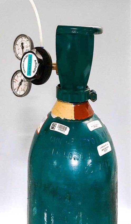
Table of Contents

Preface
Acknowledgement
Table of Contents

1.0 INTRODUCTION                                                           1
     1.1   Compressed gas                                                  2
     1.2   Compressed Gas Hazardous Properties                             3
     1.3   Objective                                                       5
     1.4   Scope                                                           5

2.0 LEGISLATIVE REQUIREMENTS                                               6
     2.1   Factories and Machinery Act 1967 (Act 139)                      6
     2.2   Occupational Safety and Health Act 1994 (Act 514)               6
           2.2.1 General        Duties   of    Employer,   Self-employed   6
                    Persons and Occupier
           2.2.2 General Duties of Designers, Manufacturers and            7
                    Suppliers
           2.2.3 General Duties of Employees                               7

3.0 DESIGN AND CONSTRUCTION                                                8
     3.1   General Requirements                                            8
           3.1.1 Additional requirements for the construction of           9
                    closed cryogenic receptacles for refrigerated
                    liquefied gases
           3.1.2 Additional requirements for the construction of           10
                    cylinders for acetylene
     3.2   Materials                                                       10
     3.3   Service Equipment                                               11
     3.4   Approval of Cylinders                                           11

                                          ii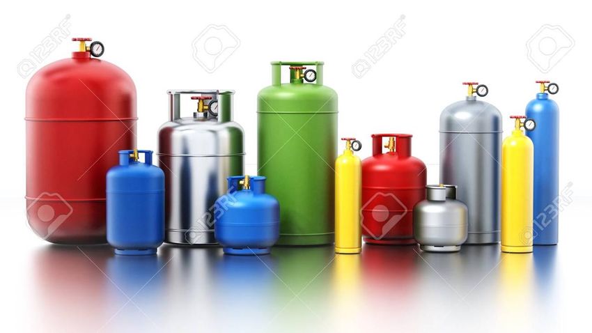
4.0 GAS CYLINDER VALVES AND REGULATORS               12
    4.1   Valve Protection                           14
    4.2   Valve Outlets                              16
    4.3   Valves With A Dip Tube                     17
    4.4   In Use                                     18
    4.5   Regulators                                 20
    4.6   Pressure Relief Devices                    21
          4.6.1 Burst Disc                           22
          4.6.2 Fusible Plug                         22
          4.6.3 Pressure Relief Valves               23
    4.7   Connecting A Valve To A Cylinder           24
    4.8   Disconnecting A Valve From A Cylinder      24
    4.9   Valves In A Operation                      24
    4.10 Storage and Transport                       25
    4.11 Damaged Valves                              25

5.0 MARKING AND LABELLING                            26
    5.1   Cylinder Marking                           26
    5.2   Gas Cylinder Content Labelling             28

6.0 HANDLING AND STORAGE                             29
    6.1   References on handling of a gas cylinder   29
    6.2   Transportation                             29
    6.3   Care and maintenance                       31
    6.4   Gas cylinder storage                       31

7.0 FILLING CYLINDERS                                32
    7.1   Filler Responsibility                      33
    7.2   Pre-filling Checks                         33
    7.3   Checks During Filling                      34
    7.4   Post Filling Checks                        34
    7.5   Decant Filling                             34
    7.6   Consequences of Over-filling               35

                                    iii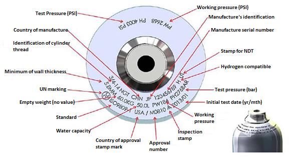
7.7   Cylinders prohibited from filling and transport         35
    7.8   Filling stations                                        35
          7.8.1 What are the requirements?                        36
          7.8.2 What equipment is required?                       36
          7.8.3 Location and infrastructure requirements of the   37
                 filling plant
    7.9   References on filling of a gas cylinder                 38

8.0 INSPECTION, TESTING AND REQUALIFICATION                       39
    8.1   Cylinder Requalification                                39

                                     iv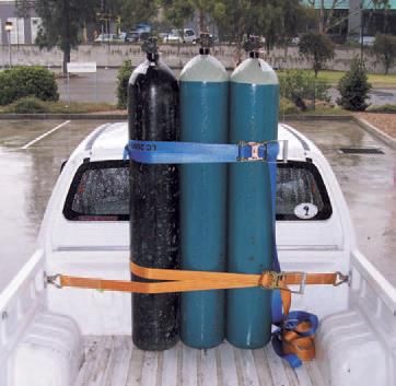
1.0    INTRODUCTION

Gas cylinders are used in a wide variety of industries, including water treatment, food
processing and laboratory. They are most commonly used in the medical and
manufacturing industries. Medical gas cylinders provide supplemental oxygen, nitrous
oxide (anesthetic functions), nitrogen (surgical tools) and carbon dioxide (to inflate
tissue). Whilst in manufacturing, gas cylinders are used for storing fuel for heating
systems, vehicles, and torches as well as storing the source of energy for power tools
or assembly line machinery.

In these guidelines, unless the context otherwise requires:

Authorised inspecting body means an Authorised inspecting body approved by the
Director General under Occupational Safety and Health (Certificated Machinery)
Regulations 20XX;

Consignor means any person, organization or government which prepares a
consignment for transport;

Cylinder means a refillable or non-refillable compressed gas container that is
commonly used for storing and transporting compressed gases and include cryogenic
receptacle (container). Non-refillable cylinders are designed for one-time use and
should never be refilled or reused. Refillable cylinders are designed for refilling and
repeated use.

Filling ratio means the ratio of the mass of gas to the mass of water at 15 °C that would
fill completely a pressure receptacle fitted ready for use;

Receptacle means a containment vessel for receiving and holding substances or
articles, including any means of closing.

                                            1
1.1   Compressed Gas

Compressed gas are gases that are stored under pressure in heavy-walled metal
cylinders. However, compressed gas is a generic term used to describe liquefied
gases, non-liquefied gases, dissolved gases and cryogenic gases which are stated
below: -

      i.   liquefied gases;
           •   gases that become liquids at normal temperatures when they are inside
               cylinders under pressure. They exist inside the cylinder in a liquid-vapour
               balance or equilibrium. Anhydrous ammonia, chlorine, propane, butane,
               nitrous oxide and carbon dioxide are examples of liquefied gases.

      ii. non-liquefied gases;
           •   also known as compressed, pressurized or permanent gases. These
               gases do not become liquid when they are compressed at normal
               temperatures, even at very high pressures. Common examples are
               oxygen, nitrogen, helium and argon.

      iii. dissolved gases;
           •   gases that dissolved in another substance. For example, acetylene.
               Acetylene is the only commonly used dissolved gas and it is dissolved
               in acetone. It is chemically unstable and flammable. Even at atmospheric
               pressure, acetylene gas can explode. When acetylene gas is added to
               the cylinder, the gas dissolves in the acetone (solution) which is very
               stable.

      iv. refrigerated liquefied gases (cryogenic liquids);
           •   refrigerated liquefied gases or cryogenic liquids are kept in their liquid
               state at very low temperatures. Refrigerated liquefied gases are
               extremely cold with boiling points below - 150° C. Refrigerated liquefied
               gases are heavier than air under cold temperature conditions. The
               vapors and gases released from refrigerated liquefied gases can be

                                            2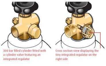
extremely cold and can result in frost bites and blisters. Small amounts
               of refrigerated liquefied gases liquid can expand into very large volumes
               of gas. Liquid helium, liquid nitrogen, and liquid argon are the examples
               of refrigerated liquefied gases.

The pressure of the gas in a cylinder is usually measured in pounds per square inch
gauge (psig) or kilopascals (kPa).

1.2   Compressed Gas Hazardous Properties

Compressed gas can have one or more hazardous properties. It does have inherent
pressure hazards and can also create health hazardous and flammable atmospheres.
Compressed gases may also be flammable, toxic, and corrosive. Examples of hazards
related to compressed gas are as following: -

      i.   high pressure;
           •   compressed gases are hazardous due to high pressures inside the
               cylinders. Even at a relatively low pressure, gas can flow rapidly from an
               open or leaking cylinder. For example, if unsecured cylinder is knocked
               over and the cylinder valve breaks, the gas can escape at a high speed
               resulting in severe injury and property damage.

      ii. asphyxiant;
           •   inert gas such as argon, neon, helium or nitrogen are hazardous
               because it can displace oxygen in the air and may lead to suffocation. If
               the oxygen level falls too low, individuals in the affected area can lose
               consciousness or die from asphyxiation.

      iii. pyrophoric;
           •   some gases, for example non-metal hydrides (diborane, silane,
               phosphine) or metal carbonyls (nickel carbonyl) are hazardous because
               it will ignite and burn spontaneously in the air.

                                             3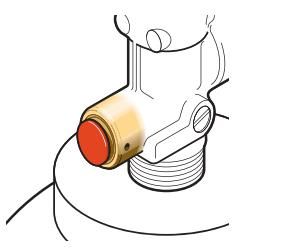
iv. cryogenic;
   •   gases that are kept in their liquid state at very low temperatures and are
       extremely cold. The main hazards related to the use of cryogenic gases
       are asphyxiation in oxygen-deficient atmospheres, fire in oxygen-
       enriched atmospheres and cold burns (hypothermia or frostbite) from
       intense cold.

v. flammable;
   •   gases such as acetylene, ethylene and butane can burn or explode in
       the air when mixed with an oxidizer in a given range of concentrations
       and provided by the ignition source. Each flammable gas has a specific
       flammable range. For a gas to be flammable, the concentration should
       be between its lower flammable limit (LFL) and its upper flammable limit
       (UFL).

vi. oxidizing;
   •   gases that contains oxygen above than atmospheric concentrations (23-
       25%), nitrogen oxides and halogen gases (chlorine and fluorine). These
       gases can react rapidly and violently with combustible materials and can
       lead to fires or explosions which are very hard to extinguish and can
       spread rapidly.

vii. corrosive;
   •   gases that can burn and destroy body tissues on contact. It can also
       attack and corroded metals. Common corrosive gases include ammonia,
       hydrogen chloride, chlorine and methylamine.

viii. poisonous (toxic);
   •   gases that have the potential to cause adverse health effects depending
       on the specific gas, its concentration, the length of exposure, and the
       route of exposure (inhalation, eye or skin contact). Exposure to this type
       of gas may lead to illnesses, severe respiratory distress, respiratory
       muscle dysfunction, or immediate death.

                                    4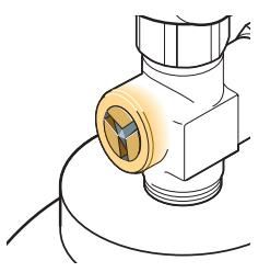
1.3         Objective

The objective of these Guidelines is to provide advice and guidance to any person or
organisation that is involved for the design, construction, handling, inspection and
testing of compressed gas cylinders, thereby reducing the risks and helps to prevent
accidental damage or injury to people, property and the environment.

1.4         Scope

These guidelines are intended to specify requirements for the design, construction,
operation and handling, inspection and testing for compressed gas cylinders of sizes
from 0.5l to 150l water capacity.

For specific gas applications such as welding, diving, inerting, etc. additional
requirements apply which are not covered in these guidelines.

These guidelines do not apply to:
  i.    Cylinders forming part of vehicle e.g NGV cylinder.
 ii.    Aerosol containers and gas catridges.
 iii.   Non-refillable cylinders.
 iv.    Fire extinguishers.
 v.     LPG cylinders.

                                           5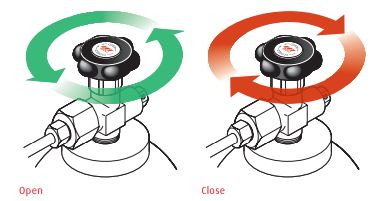
2.0    LEGISLATIVE REQUIREMENTS

Laws and regulations that related to the use of gas cylinders are as follows: -
  i.   Factories and Machinery Act 1967 (Act 139)
 ii.   Occupational Safety and Health Act 1994 (Act 514)

2.1    Factories and Machinery Act 1967 (Act 139)

Section 3 of the Act stipulate the definition of the gas cylinders, which means a steel
cylinder or bottle used for the storage and transport of compressed, dissolved or
liquefied gases and classified it as a machinery.

2.2    Occupational Safety and Health Act 1994 (Act 514)

Cylinders that has been interpreted as a machinery (FMA1967) are included in the
interpretation of ‘plant’, while gas has been interpreted as a ‘substance’ under Section
3 of the Act.
           ▪ ‘plant’ includes any machinery, equipment, appliance, implement or tool,
                any component thereof and anything fitted, connected or appurtenant
                thereto;
           ▪ ‘substance’ means any natural or artificial substance, whether in solid or
                liquid form or in the form of a gas or vapour or any combination thereof;

2.2.1 General Duties of Employer, Self-employed Persons and Occupier

Section 15 and 18 of OSHA 1994 stipulate the duties and responsibilities of the
employer, self-employed person or occupier to ensure the use of a plant or substance
are safe and without risks to health to their employees and persons other than his
employees at workplace.

                                             6
2.2.2 General Duties of Designers, Manufacturers and Suppliers
Section 20 of OSHA 1994 stipulate the general duties of a person who designs,
manufactures, imports or supplies any plant for use at work to ensure that the plant is
designed and constructed, as to be safe and without risks to health when properly
used.
Section 21 of OSHA 1994 stipulate the general duties of the person who formulates,
manufactures, imports or supplies any substance for use at work to ensure that the
substance is safe and without risks to health when properly used.
2.2.3 General Duties of Employees
Section 24 of OSHA 1994 stipulate the duties of employee while at work to take
reasonable care for the safety and health of himself and any other person, to comply
with any instruction or measure on occupational safety and health instituted by his
employer and to wear any protective equipment to prevent risks to his safety and
health.
73.0 DESIGN AND CONSTRUCTION
3.1 General Requirements
Cylinders and their closures shall be designed, manufactured, tested and equipped in
such a way as to withstand all conditions, including fatigue, during operation and
transportation.
Cylinder shall be designed and manufactured, but not limited to a current cylinder
Standard as listed below:
i. National and International Standards issued by ISO, European committee for
Standardization (CEN), Transport Canada (TC), or United States Department
of Transport (DOT).
ii. Other national standards, subject to the following requirements;
a. The standard applies to the manufacture of cylinders in the country of
origin;
b. The standard contains equivalent requirements to a Standard listed in
item (a) for material composition, properties and testing, method of
manufacture, testing including type testing and examination, rejection criteria,
marking, documentation and quality assurance.
In no case shall the minimum wall thickness be less than that specified in the design
and construction technical standards.
For welded cylinders, only metals of weldable quality shall be used.
Cylinders assembled in bundles shall be structurally supported and held together as
a unit. It shall be secured in a manner that prevents movement in relation to the
structural assembly and movement that would result in the concentration of harmful
local stresses. Manifold assemblies (e.g. manifold, valves, and pressure gauges) shall
be designed and constructed such that they are protected from impact damage and
forces normally encountered in transport. Manifolds shall have at least the same test
pressure as the cylinders. For toxic liquefied gases, each cylinder shall have an
8isolation valve to ensure that each cylinder can be filled separately and that no
interchange of cylinder contents can occur during transport.
Contact between dissimilar metals which could result in damage by galvanic action
shall be avoided.
3.1.1 Additional requirements for the construction of closed cryogenic
receptacles for refrigerated liquefied gases
The mechanical properties of the metal used shall be established for each cylinder,
including the impact strength and the bending coefficient.
The cylinders shall be thermally insulated. The thermal insulation shall be protected
against impact by means of a jacket. If the space between the cylinder and the jacket
is evacuated of air (vacuum-insulation), the jacket shall be designed to withstand
without permanent deformation an external pressure of at least 100 kPa (1 bar)
calculated in accordance with a recognised technical code or a calculated critical
collapsing pressure of not less than 200 kPa (2 bar) gauge pressure. If the jacket is
so closed as to be gas-tight (e.g. in the case of vacuum-insulation), a device shall be
provided to prevent any dangerous pressure from developing in the insulating layer in
the event of inadequate gas-tightness of the cylinder or its fittings. The device shall
prevent moisture from penetrating into the insulation.
Closed cryogenic receptacles intended for the transport of refrigerated liquefied gases
having a boiling point below -182°C at atmospheric pressure shall not include
materials which may react with oxygen or oxygen enriched atmospheres in a
dangerous manner, when located in parts of the thermal insulation where there is a
risk of contact with oxygen or with oxygen enriched liquid.
Closed cryogenic receptacles shall be designed and constructed with suitable lifting
and securing arrangements.
93.1.2 Additional requirements for the construction of cylinders for acetylene
Acetylene cylinders shall be filled with a porous material, uniformly distributed, of a
type that conforms to the requirements and testing specified by the inspection body
and which:
i. Is compatible with the cylinder and does not form harmful or dangerous
compounds; and
ii. Is capable of preventing the spread of decomposition of the acetylene in the
porous material.
In the case of dissolved acetylene, the solvent shall be compatible with the cylinder.
3.2 Materials
Gas cylinders can be made from aluminium, steel, alloys, and composite materials.
Mechanical strength, corrosion resistance, and impact resistance are critical factors in
determining which material is used.
Construction materials of cylinders and their closures which are in direct contact with
dangerous goods shall not be affected or weakened by the dangerous goods intended
to be transported and shall not cause a dangerous effect e.g. catalysing a reaction or
reacting with the dangerous goods.
Cylinders and their closures shall be made of the materials specified in the design and
construction technical standards. The materials shall be resistant to brittle fracture and
to stress corrosion cracking as indicated in the design and construction technical
standards.
103.3 Service equipment
Service equipment shall be configured or designed to prevent damage that could result
in the release of the cylinder contents during normal conditions of handling and
transport. Manifold piping leading to shut-off valves shall be sufficiently flexible to
protect the valves and the piping from shearing or releasing the cylinder contents. The
filling and discharge valves and any protective caps shall be capable of being secured
against unintended opening.
Cylinders which are not capable of being handled manually or rolled, shall be fitted
with devices (skids, rings, straps) ensuring that they can be safely handled by
mechanical means and so arranged as not to impair the strength of, nor cause undue
stresses, in the cylinder.
In case of transportation of cylinders, the valves, piping and other fittings subjected to
pressure, excluding pressure relief devices, shall be designed and constructed so that
the burst pressure is at least 1.5 times the test pressure of the cylinders.
3.4 Approval of cylinders
The conformity of cylinders shall be assessed at time of manufacture as required by
the standards or codes. Cylinders shall be inspected, tested and approved by an
authorised inspecting body. The technical documentation shall include full
specifications on design and construction, and full documentation on the
manufacturing and testing.
Quality assurance systems shall conform to the requirements of the authorised
inspecting body.
114.0 GAS CYLINDER VALVES AND REGULATORS
The main components of a typical gas cylinder and regulator assembly are shown in
Figure 4.1
Delivery Pressure Valve Guard
Gauge
Cylinder Pressure
Gauge
Regulator Pressure
Adjusting Control
Cylinder
Figure 4.1. Main components of a compressed gas cylinder and regulator assembly.
Image courtesy from Forensic Engineering Division, DOSH.
The gas cylinder valve is the primary safety mechanism on a gas cylinder and shall
not be tampered with. A valve is usually fitted into the open end of the cylinder,
normally at the top, or shoulder of the cylinder in order to allow a gas to be contained
within a cylinder and to control the release of the gases. A cap, collar, or neck ring
commonly protects the valve assembly from damage when the gas is not in use. The
valve may have several functions as follows:
• It is a means of closing an opening in a cylinder.
• It provides an inlet port to allow a cylinder to be filled.
• It provides closure to contain the contents within the cylinder.
• It provides an outlet port to allow the gas to be released.
12• It can accommodate safety devices, such as non-return valves, pressure relief
valves and residual pressure valves.
• It can incorporate an integrated pressure regulator.
• It can incorporate an outlet flow regulating device.
• It can incorporate a contents level (pressure) gauge.
• It can provide a mounting for external components, such as regulators and
pipelines.
Valves are designed, constructed, inspected, tested and approved against any
national or international standards such as Malaysia Standards or ISO. Due to the
many properties of the various gases, valves have to be manufactured from
compatible materials.
Valves are required to have the same service life and performance as gas cylinders
to allow their test pressure and their periodic inspection and test dates to align.
Typically, this can mean a minimum service life of at least 10 years for many valves,
however, where cylinders have an extended life of up to 15 years, the valve life will
need to be taken into consideration. Valves should not be used if their test pressure is
below that of the cylinder. Some common valve standards include:
• BS 341, Transportable gas container valves.
• BS EN ISO 10297, Transportable gas cylinders. Cylinder valves. Specification
and type testing.
• BS EN ISO 13340, Transportable gas cylinders. Cylinder valves for non-
refillable cylinders. Specifications and prototype testing.
134.1 Valve protection
Valves, especially on larger cylinders, are designed to withstand mechanical impact,
and do not need additional protection, but they are often protected from general
damage in a variety of ways. The following methods are common:
i. A valve guard - a device that is securely fixed around the valve, but stands
higher than the valve hand wheel. They can be of cast or welded construction
or made from non-metallic moulded plastics. They can be attached to either the
cylinder shoulder, the cylinder neck (with a Cir-clip), or in some cases, the base
of the valve. It does not need to be removed for access to the valve.
Figure 4.1: Valve guard
ii. A valve shroud - a type of valve guard but which is an integral part of a welded
cylinder or pressure drum, most commonly seen on LPG or refrigerant gas
service.
Figure 4.2: Valve shroud
14iii. A valve protection cap - a cover that is securely fixed over the valve during
handling, transport and storage which is removed for access to the valve. It is
designed not to contact the valve or the hand wheel.
Figure 4.3: Valve protection cap
The valve outlet port may be protected by:
• A temporary covering, such as a plastic sleeve, often heat shrunk over the
outlet port.
• A specialist security cap, typically manufactured from plastic, which requires a
small amount of effort to break open. Once open it cannot be refitted.
• A removable (plastic) plug, that screws onto the thread in the outlet port.
• A re-useable fill port plug, (which may be gas-tight) particularly for very high
value, risk or purity gases.
This type of protection is fitted once a cylinder has been filled and is used to prevent
contamination of the outlet port, but it also provides an indication that the gas cylinder
has not been used or tampered with.
154.2 Valve outlets
A variety of different valve outlets exist. Whilst modern standards have attempted to
standardise valve outlets such that there is an international system to prevent the
interconnection of non-compatible gases, there remain many outlets in use which are
based on traditional national standards. Care should therefore be taken to ensure that
only appropriate connections are made.
Figure 4.4: Valve outlet
The valve outlet is designed for a specific gas, or a specific hazard group. For example,
valves for non-flammable gases are fitted with right-hand threaded valve outlets,
whereas valves used for flammable gases are fitted with left-hand threaded valve
outlets.
Components that fit into valve outlets with a left-hand thread are often identified by
having a notch cut into the hexagonal connecting nut.
16Some common valve outlet standards include:
• BS 341, Transportable gas container valves.
• BS EN ISO 407, Small medical gas cylinders. Pin-index yoke-type valve
connections.
• BS ISO 5145, Cylinder valve outlets for gases and gas mixtures. Selection and
dimensioning.
Valve outlets may be configured as a top outlet or as a side outlet. More complex
valves may have more than one type of valve outlet.
• DO NOT use an adaptor to connect equipment to the valve outlet if it is not
compatible.
• DO NOT over-tighten or use excessive force to connect equipment.
4.3 Valves with a dip tube
Figure 4.5: Valves with a dip tube
Some gas cylinders that are used to contain liquefied gases incorporate valves fitted
with dip tubes. These may be identified by a white line painted on the side of the
cylinder, and / or an ‘indicator' ring under the valve.
17Dip tubes can be of various length and design and are fitted to the inlet of the valve.
They can have several functions in use, such as, allowing liquid to be withdrawn,
enabling a homogenous gas mixture during filling, and maintaining an adequate ullage
space within the cylinder.
Some valves may also have twin outlets, allowing a choice between gas or liquid
delivery.
4.4 In use
Remove any valve outlet protection which may be fitted. Carry out a visual inspection
of the gas outlet. Ensure it is clear of any contaminants. Any visible material or
moisture should be removed by cleaning with a clean, dry, lint-free cotton cloth. Do
not apply any oils or greases. For advice on connecting gas cylinders refer to BCGA
TIS 22.
Figure 4.6: Operating a cylinder valve
18The cylinder valves on all gas cylinders are opened by turning the spindle anti-
clockwise and then closed by turning the spindle clockwise. Some valves are
permanently fitted with handwheels to rotate the spindle, but others rely on the use of
an external cylinder valve key. The key is available from the gas supplier.
Before opening a valve, point the outlet away from personnel. Valves are only to be
opened slowly. An opened spindle should NEVER be left against the backstop, but
should be turned back at least half a turn to avoid seizure in an open position.
NOTE: Whilst this applies to the majority of valves, there are valves with a
specific operating requirements. It is therefore important that the correct
operating procedures are fully understood before attempting to operate a valve.
When the cylinder is in use and the valve is open, keep the cylinder valve key inserted
into the valve. In-use a cylinder should always be secured to prevent it toppling over.
Be aware that a loose cylinder falling over with a cylinder valve key inserted can act
as a lever, causing damage.
Valves should be checked for leaks using an appropriate leak detection fluid. Care
needs to be taken regarding the choice of leak detection fluids. Many valves are
manufactured from non-ferrous material such as a brass or bronze, but as copper-
based materials they are susceptible to stress corrosion cracking if exposed to amines
or ammonia, yet many leak detection fluids contain these chemicals. For reference,
refer to EIGA Document 78, Leak detection fluids cylinder packages.
194.5 Regulator
The regulator is the next most important safety device to be fitted to a gas cylinder
before operation or use. It allows for the high pressure of the cylinder contents to be
brought down to a usable working pressure. Regulators come as single stage for short
term applications and two stages for long term applications. Regulators are also
constructed from different materials, mainly brass or stainless steel.
The application will define the required regulator. Consult the gas supplier to confirm
which kind of regulator to use.
Regulators are designed to be fitted directly to the cylinder valve. No other fittings,
connections or lubricants shall be used to connect a regulator to a gas cylinder valve.
Regulators for flammable gases are left hand threaded and have a notch cut out of
faces on the securing nut to distinguish them from non-flammable gas regulators.
Figure 4.5.1: Example of single stage regulator
Always connect a gas cylinder to the item being charged via a regulator and any
appropriate pressure system components. Note that some valves are designed
complete with a regulator, such as a VIPR (Valve with Integrated Pressure Regulator),
which include pressure and sometimes flow regulation, making them suitable for
connection directly to devices, or even people!
20Figure 4.5.2: Example of integrated pressure regulator
Where the gas cylinder valve assembly has a residual pressure valve and/or a non-
return valve fitted, the user shall not interfere with or remove these devices. A residual
pressure valve retains a positive gas pressure inside the cylinder. This pressure
prevents the possible ingress of contaminants into the cylinder should the valve be left
open. The non-return feature prevents back flow whenever the cylinder is at a lower
pressure than the application (involving a fluid) to which it is connected. The use of
these devices will have been assessed by the cylinder owner (usually the gas supplier)
and will form part of the construction requirements of the cylinder and valve assembly.
4.6 Pressure Relief Devices
Most cylinders or manifolded cylinder packs are fitted with a relief device. In a situation
where excess pressure is encountered, this is designed to discharge cylinder contents
either completely or only discharge the excess pressure. Discharge of a pressure relief
device will be accompanied by a high pitched noise and a jet of gas at high speed.
There are three types of commonly used pressure relief devices:
• Burst disc (most common)
• Fusible plug (e.g. acetylene)
• Pressure relief valve (e.g. LPG)
214.6.1 Burst disc
In the event of overpressure, this is designed to burst, leaving an open passage for
gas contents to escape completely.
e.g. Carbon Dioxide (CO2) cylinders are fitted with a burst disc which operates at
approximately 207 bar and is fitted on the cylinder valve.
Figure 4.9: Burst disc
4.6.2 Fusible plug
This is designed to melt when the cylinder is exposed to high temperatures and will
completely release the cylinder contents.
e.g. Acetylene cylinders are fitted with fusible plugs which melt at approximately
100°C.
22Figure 4.10: Fusible plug
4.6.3 Pressure Relief Valves
This valve is designed to relieve excess pressure and close again after relieving the
excess pressure.
e.g. LPG cylinders are fitted with pressure relief valves which operate at approximately
26 bar.
Figure 4.11: Pressure relief valves
234.7 Connecting a valve to a cylinder
There are a variety of threaded connections available for connecting a valve to a gas
cylinder. The choice of valve will be determined by the gas supplier. Before fitting a
valve, it should be inspected to ensure it is serviceable, it is suitable for the gas
contained within the cylinder, and it has sufficient life remaining, for example, to allow
its use until the gas cylinder is due its next inspection and test.
The type of threaded connection used is important in terms of achieving a seal without
causing valve material strain. There are two common types:
Tapered thread - these seal through the use of a sealant on the threads, such as PTFE
tape, and the application of a specified torque. European examples include 17E, 18T
and 25E.
Parallel thread - these seal against a captured ‘O' ring seal to the shoulder of the valve
body, as the valve is clamped down on to the flat face of the cylinder. For this type of
seal an additional sealant should not be used. European examples include M18, M25
and M30.
4.8 Disconnecting a valve from a cylinder
Cylinders contain gases under pressure. Valves should only be removed under the
authority of the cylinder owner taking all necessary precautions to do so safely. In-use,
valves should never be removed or exchanged by customers.
4.9 Valves in operation
There are two main types of valve design for controlling the flow of gas.
The simplest design makes use of an ‘O' ring. This operates in a similar manner to a
domestic water tap. The wetted area is sealed against the spindle by an ‘O' ring(s)
located around the spindle. This type of valve is acceptable for general use.
24A more comprehensive design utilises a diaphragm. The spindle is connected to a
flexible diaphragm, which it moves up and down to open and close the flow. This
design prevents any possible gas flow past the spindle. This type of valve is used to
control high value or high risk gases, where even small leaks are undesirable, for
example in laboratory situations.
4.10 Storage and transport
When a gas cylinder is not in use, for example when in storage or being transported,
the valve should always be closed. This will not only stop gas escaping, but on a
nominally empty cylinder it will also prevent contamination entering the cylinder and
help to maintain its integrity.
Where provided, valve protection caps should always be fitted.
4.11 Damaged valves
If you have a gas cylinder with a damaged valve, do not use the cylinder and seek the
advice of gas supplier. If safe to do so, move the gas cylinder to a secure place and
quarantine it until appropriate action is taken.
255.0 MARKING AND LABELLING
Every cylinder and their contents must be identified for the clear benefit of all users,
fillers, periodic testers, transporters, emergency responders as well as any other
persons coming into contact with the cylinder and/or its contents. These requirements
are shown in Table 5.1.
Table 5.1: Identification of cylinders and their contents
Item Form of Marking
Cylinder identification (manufacture,
standards, test dates, approval number, Stamped or permanently marked
etc)
Valves and fittings identification Stamped or permanently marked
Gas identification
User warning identification Adhesive or attached labels
Filling station identification
5.1 Cylinder marking
Different countries have different color coding systems that are used to classify
different gases and types of cylinders. In order to provide the information of the
cylinders, these identification markings are used to indicate important data about the
capabilities, ownership, and inspection history of the cylinder. More information can
be seen in Figure 5.1.
The ISO 13769: Gas Cylinders – Stamp Marking is the standard which apply to the
marking of compressed gas cylinders.
26Figure 5.1: Example of UN-ISO markings
Legend:
Top row: Contains manufacturing marks such as the cylinder thread type, the
country of manufacture, and the serial number.
Middle row: Contains operational marks such as the minimum wall thickness, the
tare or empty weight, water capacity in liter, working pressure (PW) in bar, and test
pressure (PH) in bar.
Bottom row: Contains certification marks such as the UN packaging symbol, the
ISO standard, the country or countries of approval, the manufacturer’s approval
mark, the approved third party independent inspection agency identification stamp,
and the initial inspection year and month separated by a slash.
Additional information: -
✓ Never rely on the color of the cylinder for gaseous chemical identification. Color-
coding is not reliable because colors can vary with the supplier.
✓ Never rely on the color of the cylinder cap for gaseous chemical identification.
27✓ Never rely on the label affixed on the cap, if any. Caps can be easily
interchanged.
✓ Never use a cylinder whose contents cannot be positively identified.
✓ Do not remove or deface any marks or tags attached to the cylinder by the
supplier.
✓ If the labeling or the attached tag on a cylinder becomes unreadable or is missing,
the cylinder should be marked “contents unknown” and returned to the supplier.
5.2 Gas Cylinder Content Labelling
Where a gas cylinder contains a hazardous substance, it must be identified and
labelled to the classifications of the hazardous substance, the adverse effects and the
general precautions that need to be taken in order to prevent the adverse effects.
It is the filler’s responsibility to ensure that all cylinders they fill are correctly labelled
as to the cylinder’s contents.
Before using any gas, read the label and safety data sheet information associated with
the specific gas. Gas cylinder with more than one hazard label carry contents with
more than one hazardous property. The labelling shall be in accordance with the
National Occupational Safety and Health Regulation (Chemical Classification,
Labelling and Safety Data Sheets).
286.0 HANDLING AND STORAGE
The contents of a cylinder store the energy that has gone into compressing them, and
if the cylinder is weakened, this mechanical energy may be released violently. Some
gases store a considerable amount of chemical energy, and may react chemically with
the environment. In either case, the chemical energy will augment the mechanical
energy and increase the violence of the release.
Cylinders should be stored, handled and used in an upright attitude wherever possible,
unless they have been specifically designed for horizontal use. Most general purpose
gas cylinders are designed for use in the upright (vertical) attitude. Cylinders such as
vehicle cylinders and forklift cylinders are designed for use in the horizontal attitude
although forklift cylinders may normally be handled and stored vertically.
Acetylene cylinders contain acetone as a solvent for the gas, and must be used upright
to avoid the possibility of acetone being discharged with the acetylene. If transported
horizontally, they must be stood upright for at least one hour before use.
6.1 References on handling of a gas cylinder
The following standards may apply for the handling of a gas cylinder;
a. MS 2560:2014 Gas Cylinders – Safe Handling (First Revision)
b. ISO 11625:2007 Gas Cylinders – Safe Handling
6.2 Transportation
This section should be read in conjunction with any rules and regulation in Malaysia
which set out the requirements for such things as load segregation, documentation,
placarding and load security.
29Cylinders should be secured when being transported. Examples of preferred methods
include:
a. cylinder(s) restrained in the upright attitude by way of tie-down straps or
ropes (Refer Figure 6.1);
Figure 6.1: Example of correct positioning and restraining of gas cylinders
b. cylinder(s) suitably supported in bins, racks or suitably approved
transportation devices; or
c. cylinders in customised supporting ‘cradles’ or chocks that are designed to
prevent the cylinder(s) from rolling.
Flammable gas cylinders should not be stored in the same compartment or the same
part of the vehicle as the driver or passengers. No part of the cylinder or valve should
project beyond the dimensions of the vehicle that is transporting them.
306.3 Care and maintenance
Adequate precautions should be taken at all times to prevent damage to the cylinder
during transportation, handling, storage or use.
Protective coatings on cylinders should also be maintained in good condition.
6.4 Gas cylinder storage
Irrespective of the type of gas or the quantity stored, gas cylinders should be stored in
a location that:
a. is suitable for the type and quantity stored;
b. is secured;
c. is well ventilated;
d. in the case of flammable gases, is of fire resisting construction;
e. in the case of flammable gases or oxidising gases, is suitably separated from
potential sources of ignition;
f. in the case of flammable or toxic gases, is not in a person’s work area and
the quantities stored meet the required separation distances from areas of
high and low intensity land use (note that use of such gases);
g. may need to be in a person’s work area – such as medical gases in a
hospital;
h. in the case of flammable or oxidising gases, has portable fire extinguishers
available;
In addition to the above, it is good practice for the cylinders to be protected from the
weather.
317.0 FILLING CYLINDERS
Cylinders should be filled by a trained person, namely filler. To become a filler, a
person should know and familiar with:
a. the different forms of compressed gases, namely –
i. low pressure liquefied gas;
ii. high pressure liquefied gas;
iii. permanent gas; and
iv. cryogenic gas;
b. the factors that can trigger failure of a cylinder;
c. the potential adverse effects associated with the different forms of
compressed gas;
d. the requirements of relevant standards or codes covering the visual
inspection and safe charging of a cylinder including what is/are:
i. an approved cylinder design
ii. cylinder filling terminology, e.g., tare weight, empty weight, ullage, filling
ratio, water capacity, working pressure, test pressure
iii. cylinder safety devices
iv. test periods for types of cylinders the filler will be charging
v. cylinder markings
vi. valve markings
vii. the different types of valves fitted to cylinders the filler will be charging
viii. external visual inspection of cylinders for general condition
ix. in the case of a liquefiable gas cylinder, how to correctly calculate the
maximum filled weight using the formula:
MAXIMUM FILLED WEIGHT = (WATER CAPACITY x FILLING RATIO) + TARE
OR EMPTY WEIGHT
“tare weight” in relation to -
(1) acetylene cylinder means the weight of the cylinder together with any fittings,
permanently attached and includes the weight of valve any safety device, porous
32mass, requisite quantity of solvent for dissolving acetylene, and the weight of
acetylene gas saturating the solvent at atmospheric pressure and temperature of 150
C;
(2) liquefiable gas cylinder means the weight of the cylinder together with any fittings
permanently attached thereto and includes the weight of valve;
(3) permanent gas cylinder means the weight of the cylinder together with any fittings
permanently attached thereto and excludes the weight of valve;
7.1 Filler Responsibility
The filler is responsible to record the movement of each cylinder and the date of the
cylinder to be re-qualified. Only cylinders with a valid requalification date can be
refilled.
7.2 Pre-filling checks
Before filling a cylinder, the filler should ensure that:
a. the cylinder is marked according to standard followed;
b. the cylinder is within its required test period;
c. the cylinder is in good external physical condition;
d. the cylinder markings and labelling are clear and correspond to the gas to be
filled;
e. the valve is suitable and in good condition;
f. where required, an over-pressure protection device is fitted, e.g., pressure
relief valve, burst disc.
Prior to filling, the filler shall perform an inspection of the cylinder and ensure that the
cylinder is authorized for the gas. Shut-off valves shall be closed after filling and remain
closed during transport. The consignor shall verify that the closures and equipment
are not leaking.
337.3 Checks during filling
Once a cylinder has commenced being filled, the filler should ensure that:
a. the cylinder valve is not leaking via its neck threads, or valve spindle;
b. the rate of filling does not exceed the manufacturer’s recommendation for
the cylinder design; and
c. the filler remains in attendance at the filling point at all times while the
cylinder is being filled.
7.4 Post filling checks
After filling a cylinder, the filler should ensure that:
a. the cylinder is correctly labelled in accordance with section 5.2 of this
guidelines;
b. the cylinder is labelled with the name or other suitable identification of the
filling station;
c. the cylinder has been checked for leaks by soap testing the valve or
immersing the cylinder and valve in a water bath; and
d. the final fill pressure or filled weight has not exceeded the marked fill
pressure or the calculated maximum filled weight respectively.
7.5 Decant filling
Decant filling by weight control is the only permitted method that can be used to fill
cylinders having a water capacity less than 5 litres. Decant filling is a controlled
delivery using only the pressure from the supply cylinder or tank to transfer the gas,
and is not pump assisted.
347.6 Consequences of over-filling
If a liquefied gas cylinder is over-filled, then the expansion of the liquid phase as the
temperature increases may cause the cylinder to become ‘liquid-full’ with no remaining
ullage space. If the temperature continues to rise, the pressure in the cylinder will rise
disproportionately. At the very least, liquid will be forced out of the pressure relief valve
risking malfunction of attached appliances and a fire. If there is no pressure relief valve,
or it fails to operate, the cylinder may burst after only a small rise in temperature.
7.7 Cylinders prohibited from filling and transport
Cylinders shall not be offered for filling and transport:
a. When leaking;
b. When damaged to such an extent that the integrity of the cylinder or its service
equipment may be affected;
c. When the cylinder is beyond its requalification time limit.
Cylinder may be offered for filling and transport when:
a. the cylinder and its service equipment has been examined and found to be
in good working order;
b. the required certification, retest, and filling markings are legible.
7.8 Filling stations
The occupier of the site is normally the person with day to day responsibility for its
operation. The occupier is responsible for ensuring that the requirements of the Act
and regulations are met at all times. This person must ensure a high standard of filler
competence and that filling station equipment is well maintained.
357.8.1 What are the requirements?
The occupier must ensure that:
a. all persons filling cylinders are trained for the gas traffic and cylinder types
filled, and that a copy of each training certificate is available on site;
b. all equipment necessary to safely fill cylinders is provided and maintained;
and
c. the cylinder filling and cylinder storage areas are separated by the required
distances and are kept orderly and tidy.
7.8.2 What equipment is required?
The occupier must ensure that the following items of equipment are provided and
maintained:
a. Cylinder filling instructions
b. Filling hoses of a suitable pressure rating and suitable for the gas being
filled
c. All required cylinder filling connections
d. Soapy water solution or a water bath, for leak checking
e. For filling liquefied gases, calibrated weighing scales of a type suitable
for the gas being filled
f. For filling of flammable gases, a portable fire extinguisher is provided
g. All hand tools necessary for fitting and removing filling connections, e.g.
adjustable spanner, flat bladed screwdriver, etc
h. Filling station identification labels
i. All other labels required for identification of cylinder contents
j. Leather gloves
k. Eye protection
l. First-aid kit on site
m. Warning signage
367.8.3 Location and infrastructure requirements of the filling plant
The area where the filling operation is to take place shall:
a. be an external area or inside a structure which has been assessed to assure
there is a high ventilation rate. Filling shall not take place in an enclosed area.
b. be constructed primarily of non-flammable materials;
c. be constructed using compatible materials, for example, when filling with
oxygen avoid the use of oil, greases and bitumen products;
d. have fire-fighting equipment / facilities;
e. have an electrical installation adequately rated for the area in which it is
installed;
f. have adequate lighting;
g. be exclusively for the filling operation;
h. have no other hazardous products stored within the filling area;
i. take into account human factors in the design of the filling equipment and the
operations around it;
j. be ergonomically designed and laid out, for example, to ensure visibility of
pressure gauges and access to valves;
k. be subject to regular housekeeping, including the collection and removal of all
combustible products, such as packaging, which are no longer required;
l. have multiple independent escape routes available. Emergency exits shall not
require a key, card, or code to operate. All exits shall be able to be opened from
the inside, for example, by the use of a push bar.
During the site risk assessment the hazard from oxygen depletion and enrichment
shall be assessed, as well as the hazard due to any other properties of the gases on-
site. This may require an assessment for the use of gas detection equipment. The use
of monitoring equipment, such as close-circuit television (CCTV), is recommended
during filling plant operation.
377.9 References on filling of a gas cylinder
The following standards may apply for the filling of a gas cylinder;
a. ISO 24431: Gas Cylinders -- Seamless, Welded and Composite Cylinders
for Compressed and Liquefied Gases (Excluding Acetylene) -- Inspection
at Time of Filling;
b. ISO 11622:2005: Gas cylinders -- Conditions for filling gas cylinder
c. ISO 11755: Gas Cylinders -- Cylinder Bundles for Compressed and
Liquefied Gases (Excluding Acetylene) -- Inspection at Time of Filling
388.0 INSPECTION, TESTING AND REQUALIFICATION
New cylinders shall be subjected to testing and inspection during and after
manufacture in accordance with the applicable design standards.
The following standards or documents may apply to the periodic inspection, testing
and requalification of compressed gas cylinders:
a. MS 1720: Welded Carbon Steel Gas Cylinders – Periodic Inspection and
Testing
b. ISO 6406: Gas Cylinders – Seamless Steel Gas Cylinders – Periodic
Inspection and Testing
c. ISO 18119: Gas cylinders -- Seamless steel and seamless aluminium-
alloy gas cylinders and tubes -- Periodic inspection and testing
d. ISO 10460: Gas cylinders -- Welded carbon-steel gas cylinders -- Periodic
Inspection and Testing
e. ISO 11623: Gas cylinders -- Composite Construction -- Periodic
Inspection and Testing
f. AIGA090/14: A Reference Guide for Requalification of Gas Cylinders
8.1 Cylinder requalification
A cylinder shall be due for periodic inspection and tests on its first receipt by a filler
following the expiry of the interval established in national and international standards.
Provided that the cylinder has been subjected to normal conditions of use and has not
been subjected to abusive and abnormal conditions that would render the cylinder
unsafe, there is no general requirement for the user to return a gas cylinder before the
contents have been used even though the periodic inspection and test interval may
have lapsed.
It is the responsibility of the owner or user to submit the cylinder for periodic inspection
and test within the interval specified by relevant cylinder design standards. Reference
39shall be made to the manufacturer or inspection body if there is a question on the re-
test period for specific gases.
No cylinder shall be refilled beyond the expiry date of requalification.
Requalification period of a cylinder shall follow any national and international
standards recognised by the countries.
For compressed gases service, the UN recommended period for requalification is a 5
year interval. A 10 year interval may be used if the dryness of the product and that of
the filled cylinder are such that there is no free water. This condition shall be proven
and documented within a quality system of the filler. If these conditions cannot be
fulfilled, alternative or more frequent testing may be appropriate, according to the
recommendations.
For UN 1001 acetylene, dissolved, the test period is 10 years.
For UN 3374 acetylene, solvent free, the test period is 5 years.
Under certain conditions, a shorter time interval for requalification may be required at
all times, e.g. the dew point of the gas, polymerization reactions and decomposition
reactions, cylinder design specifications, change of gas service, etc.
Failed cylinders cannot be repaired and must be disposed of in a safe manner.
40You can also read