SWATHPRO INSTRUCTIONS FOR CONTINUED AIRWORTHINESS - FOR AIRTRACTOR - CAPSTAN AG
←
→
Page content transcription
If your browser does not render page correctly, please read the page content below
TM

               Instructions for
           Continued Airworthiness

            SwathPRO™
                                   For AirTractor

                              DRAFT
320700-005 Rev. X4 | Revised 02/2021 | ©2021 Capstan Ag Systems, Inc.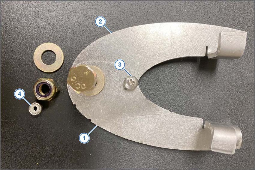
This page intentionally left blank

DRAFT
TM

                                                                                                          Change Log

    Change Log
            Revision          Pages                              Description                             Date
                A                 All     Initial Release of the Instructions for Continued          XX/XX/2020
                                          Airworthiness of the SwathPRO™ system

    Revisions and Amendments
         All ICA changes will be submitted to the FAA for review and acceptance by the Aircraft Certification
         Office and the Aircraft Evaluation Group prior to issuance to the field. Revisions to this ICA may not
         be distributed without prior FAA acceptance. Once an ICA revision is accepted by the FAA, it shall
         be distributed to all registered owners by either U.S. mail, internet, or email at the election of the STC
         holder. For questions or assistance regarding these Instructions for Continued Airworthiness, contact:

                                                  Capstan Ag Systems, Inc.
                                                   4225 SW Kirklawn Ave.
                                                      Topeka, KS 66609
                                    Toll-free number: (855) 628-7722 | Fax: (785) 232-7799
                                              CapstanAG.com | CapstanAG.ca
                                                prodsupport@capstanag.com

© 2021 Capstan Ag Systems, Inc.
                                   DRAFT                        iii                               SwathPRO Maintenance
TM

                                                                                                                                                      Contents

    Contents
         Change Log.............................................................................................................. iii
                 Revisions and Amendments.......................................................................................................iii
         References.............................................................................................................. viii
                 Acronym List...............................................................................................................................ix

         Section 1: Introduction....................................................................... 11
                 This Manual...............................................................................................................................12
                 Applicable Aircraft Models........................................................................................................ 12
                                                    ™
                 Modification for SwathPRO .....................................................................................................13
                 Required and Special Tools..................................................................................................... 13

         Section 2: Safety................................................................................. 15
                 Signal Words.............................................................................................................................16
                 Emergency Safety.....................................................................................................................16
                 Personal Protective Equipment.................................................................................................16
                 Pressurized Fluid Lines............................................................................................................ 16
                 Chemical Safety........................................................................................................................ 16

         Section 3: Warranty.............................................................................17
                 Limited Warranty....................................................................................................................... 18

         Section 4: Airworthiness Limitations................................................ 21

         Section 5: Installation......................................................................... 23
                 Before Installation of the CapstanAG™ System....................................................................... 24
                 Install the SwathPRO™ Booms................................................................................................ 24
                 Post-install Checklist................................................................................................................. 25
                 System Dry Tests..................................................................................................................... 25
                         Do the Boom Dry Test...................................................................................................25
                         Do the Key Fob Boom Dry Test....................................................................................26
                 System Wet Test...................................................................................................................... 27
                         Do the Key Fob Boom Wet Test................................................................................... 27
                 Remove the SwathPRO Booms............................................................................................... 29
                 Install Conventional (OEM) Booms.......................................................................................... 30

         Section 6: System Operation............................................................. 33
                 Start the CapView.....................................................................................................................34
                 Main Operation Screen.............................................................................................................35
                 Upload a Profile to the CapView.............................................................................................. 36
                 Shut down the CapView........................................................................................................... 37
                 Do a Forced Shutdown—Unresponsive CapView....................................................................38

© 2021 Capstan Ag Systems, Inc.
                                       DRAFT                                       iv                                                 SwathPRO Maintenance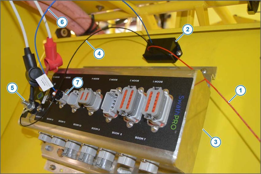
TM

                                                                                                                                                        Contents

         Section 7: Maintenance...................................................................... 39
                Service the System...................................................................................................................40
                Jump Start, Weld On, or Charge the Machine.........................................................................40
                                            ™
                Winterize the SwathPRO System...........................................................................................40
                Recommended Guidelines for Maintenance/Service................................................................41
                Access the SwathPRO System Components...........................................................................42
                Maintenance Service Intervals..................................................................................................43
                Flush the System...................................................................................................................... 44
                Baseline Evaluation Process.................................................................................................... 45
                Examine the System.................................................................................................................45
                Examine Specific System Components....................................................................................46
                       Examine the Harnesses.................................................................................................46
                       Nozzle Valves.................................................................................................................52
                       Examine the CapView and Harnesses.......................................................................... 56
                       Examine the Gateway Hub............................................................................................ 59
                       Examine the Power Supply............................................................................................59
                How to Replace the GPS Receiver..........................................................................................62
                How to Replace the Pressure Sensor...................................................................................... 64
                Do the Factory Reset Procedure..............................................................................................66
                Do the Location Setup Procedure............................................................................................ 67

         Section 8: Schematics........................................................................ 69
                System Layout.......................................................................................................................... 70
                Nozzle Type and Component Identification..............................................................................72
                      Valve Assembly Components........................................................................................ 72
                      Alternate Valve Assembly Components.........................................................................73
                      Center Valve Assembly Components............................................................................ 74
                      Alternate Center Valve Assembly Components.............................................................75
                Gateway Hub Identification.......................................................................................................76
                      Gateway Hub Connector Pin Identification.................................................................... 77
                Pressure Sensor Harness.........................................................................................................79
                Gateway Boom Control Extension Harness............................................................................. 80
                CapView Display Harness........................................................................................................ 81
                Boom Control Harness............................................................................................................. 81
                SWATHPRO MAIN Circuit Breaker Switch.............................................................................. 82
                VCM Assemblies.......................................................................................................................83
                      Center VCM Harness Assembly.................................................................................... 83
                      VCM Harness Assembly................................................................................................ 84

         Section 9: Troubleshooting................................................................ 85
                Troubleshooting Charts.............................................................................................................86
                Interchange the Components................................................................................................... 88
                Fuses.........................................................................................................................................88
                Coil Assembly Test................................................................................................................... 89
                CapView Battery Voltage Test..................................................................................................90
                Do a Check of the System Load Capacity...............................................................................91
                VCM Voltage Test.....................................................................................................................92
                Pressure Sensor Signal Test....................................................................................................93

© 2021 Capstan Ag Systems, Inc.
                                       DRAFT                                        v                                                   SwathPRO Maintenance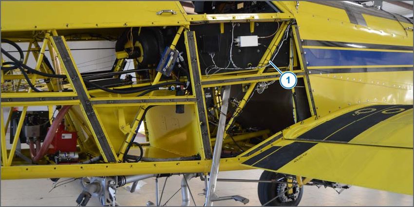
TM

                                                                                                                                   Contents

         Index......................................................................................................................... 95

© 2021 Capstan Ag Systems, Inc.
                                    DRAFT                                 vi                                         SwathPRO Maintenance
TM

                                                                                  Contents

                                   This page intentionally left blank

© 2021 Capstan Ag Systems, Inc.
                                  DRAFT               vii               SwathPRO Maintenance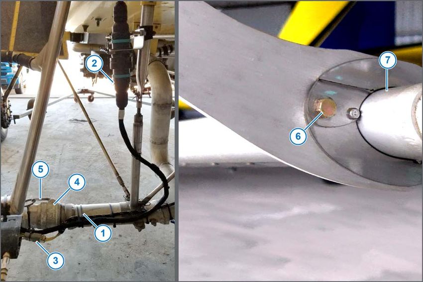
TM

                                                                                                             References

    References
         Table 1: Reference List

                                   Title                           Part Number             Description
          Pilot’s Operating Handbook and FAA Approved            320700-001      System operation information
          Airplane Flight Manual for SwathPRO™
          SwathPRO™ Installation Manual                          320700-007      System installation information
          ProMaker User Guide                                    320700-002      Computer software manual to
                                                                                 make profiles
          Acceptable Methods, Techniques, and Practices          AC 43.13-1B     Aircraft inspection and repair
          - Aircraft Inspection and Repair                                       information

         Table 2: AN Part Numbers and Torque Specifications

          CapstanAG                          Description                      AN Part Number        Torque
          Part Number                                                                             Specification
          713600-012         Washer, Mil-Spec, 1/4, Cad Plated             AN960C416L
          713600-010         Washer, Mil-Spec, 5/16, Cad Plated            AN960-516L
          713501-527         Nut, Hex, Nylok, 5/16-24, Cad Plated          AN365-524A           100-140 in/lbs
          713501-526         Nut, Stop, Hex, Thin, 6-32, Cad Plated        AN364-632A           11-13 in/lbs
          713501-525         Nut, Stop, Hex, Thin, 1/4-28, Cad Plated      AN364-428A           30-40 in/lbs
          713501-419         Bolt, Mil-Spec 5/16-24 x 31/32, Cad Plated    AN5-7A
          713501-454         Bolt, Hex 10-32 x 21/32 Cad Plated            AN3-5A
          713501-531         Nut, Hex Elastic Stop, 10-32 Cad Plated       AN365-1032A          20-25 in/lbs
          713600-013         Washer, Flat, #10 Cad Plated                  AN960-10
          713501-427         Bolt, Hex 3/8-24 x 31/32 Cad Plated           AN6-7A
          713501-521         Nut, Hex Elastic Stop, 3/8-24 Cad Plated      AN365-624A           160-190 in/lbs
          713501-014         Washer, Flat, 3/8 Cad Plated                  AN960-616L
          713501-428         Screw, 4-40 x ¾” Cad Plated                   MS35206-219
          713501-522         Nut, 4-40, thin, Cad Plated                   AN364-440A           3-4 in/lbs
          713600-015         Washer, 4-40, Cad Plated                      AN960-4L
          713501-417         Screw, 1/4-28 x 5/8" Cad Plated               MS35207-280

          The published torque values do not include the rotational drag of the elastic stop nuts (AN365).
          Standard maintenance practice dictates that mechanics add this value to the specified torque. A
          random sample of new and used AN365-4, and -5 nuts shows that the torque required to turn AN4
          (1/4") nuts varied between 15-19 in/lbs. The torque required on AN5 (5/16") nuts varied between
          18-22 in/lbs. This value must be added to the torque value.

© 2021 Capstan Ag Systems, Inc.
                                  DRAFT                        viii                                SwathPRO Maintenance
TM

                                                                                        References

    Acronym List
                  Acronym                                         Description
          FAA                     Federal Aviation Administration
          OEM                     Original Equipment Manufacturer
          VCM                     Valve Control Module
          SDS                     Safety Data Sheet
          PPE                     Personal Protective Equipment
          DTM                     Deutsch Mini
          DT                      Deutsch
          RMA                     Return Merchandise Authorization
          PWM                     Pulse Width Modulation
          LED                     Light Emitting Diode
          CAN                     Controller Area Network
          CB                      Circuit Breaker

© 2021 Capstan Ag Systems, Inc.
                                  DRAFT                     ix                  SwathPRO Maintenance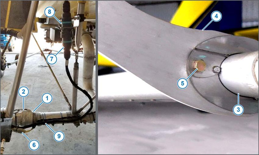
TM

                                                                                References

                                   This page intentionally left blank

© 2021 Capstan Ag Systems, Inc.
                                  DRAFT               x                 SwathPRO Maintenance
TM
Introduction
Section 1: Introduction
Topics:
• This Manual
• Applicable Aircraft Models
• Modification for SwathPRO
• Required and Special Tools
© 2021 Capstan Ag Systems, Inc.
DRAFT 11 SwathPRO MaintenanceTM
Introduction
This Manual
Important: This document must be placed into the aircraft operator’s Aircraft Maintenance Manual
and incorporated into the aircraft’s scheduled maintenance program.
For any case in which the instructions in this document and the Aircraft Maintenance Manual are in
conflict, the most restrictive instructions take precedence.
This manual includes maintenance and re-installation information for the SwathPRO™ system you
purchased.
Make sure that all personnel has read this manual other referenced manual(s) and thoroughly
understand the safe and correct operation, maintenance, and re-installation procedures.
The right and left sides of the system are determined by facing the direction of forward travel of the
aircraft on which the system is installed.
This manual contains important information on how to safely and correctly reinstall, operate, and
maintain the SwathPRO™ system. These instructions help keep personnel safe, reduce downtime,
and increase the reliability and life of the equipment, its components, and related systems.
Review the safety information in the manual(s) listed in the reference section of this manual. For more
information, go to References.
Follow the instructions (in this manual) and in the other referenced manual(s) for each step to make
sure that work conditions in and around the aircraft are safe.
It is important for all individuals working with chemicals to understand the potential risks, necessary
safety precautions, and proper response in the event of accidental contact. Reference the specific
chemical manuals for safety information.
Read, understand, and review the procedures in this manual and other referenced documents. Use
the Safety Data Sheets (SDS) and the required Personal Protective Equipment (PPE) for hazardous
chemicals.
If you do not understand the SwathPRO™ system after reading this manual and referenced
documentation, please obtain the proper training before operating, servicing, or reinstalling the
system. Proper training is important for your own safety, as well as your co-workers' safety, is
maintained.
Applicable Aircraft Models
See the STC AML for applicable aircraft models.
© 2021 Capstan Ag Systems, Inc.
DRAFT 12 SwathPRO MaintenanceTM
Introduction
Modification for SwathPRO™
The SwathPRO™ system removes and replaces the factory spray booms.
The system added electronically controlled spray valves to control spray patterns.
The CapView display in the aircraft cockpit lets the pilot upload custom spray patterns and save
preset pattern profiles for selection in-flight.
Spray on/off is controlled by the use of the existing spray handle (with no changes) or rate controller,
as applicable.
The SwathPRO™ system is compatible with aftermarket rate controllers and spray nozzles.
Required and Special Tools
Tool Description Where Used
Torque wrench Install the SwathPRO™ Booms
5 psi water line and a camlock fitting on the For the Do the Key Fob Boom Wet Test.
end of each boom
For the Flush the System.
Voltmeter For the Coil Assembly Test.
For the CapView Battery Voltage Test.
For the Do a Check of the System Load Capacity.
For the VCM Voltage Test.
For the Pressure Sensor Signal Test.
© 2021 Capstan Ag Systems, Inc.
DRAFT 13 SwathPRO MaintenanceTM
Introduction
This page intentionally left blank
© 2021 Capstan Ag Systems, Inc.
DRAFT 14 SwathPRO MaintenanceTM
Safety
Section 2: Safety
Topics:
• Signal Words
• Emergency Safety
• Personal Protective Equipment
• Pressurized Fluid Lines
• Chemical Safety
© 2021 Capstan Ag Systems, Inc.
DRAFT 15 SwathPRO MaintenanceTM
Safety
Signal Words
DANGER: Indicates an imminent hazard which, if not avoided, will result in death or
serious injury. This signal word is limited to the most extreme situations, typically for aircraft
components that, for functional purposes, cannot be guarded.
Warning: Indicates a potential hazard which, if not avoided, could result in death or serious
injury, and includes hazards that are exposed when guards are removed. It may also be used
to alert against unsafe practices.
CAUTION: Indicates a potential hazard which, if not avoided, may result in minor or moderate
injury. It may also be used to alert against unsafe practices.
Important: This is used to draw attention to specific information that is necessary for the operation,
setup, or service of the system.
Note: This is used for additional information that can help understand or operate the system.
Emergency Safety
Fire extinguishing systems must meet the applicable OSHA requirements, and all users of portable/
fixed fire suppression equipment must know the types, limitations, and proper uses of this equipment;
including hazards involved with incipient stage firefighting.
Keep emergency numbers for doctors, ambulance service, hospital, and fire department near your
telephone.
Know the location of fire extinguishers and first aid kits and how to use them.
Examine the fire extinguisher and service the fire extinguisher regularly.
Follow the recommendations on the instructions plate.
Very small fires can be put out (extinguished) with a fire extinguisher. Use an appropriate method to
extinguish a fire (water for paper fires, and chemical extinguishers for electrical or chemical fires).
Personal Protective Equipment
Wear close-fitting clothing and the correct personal protective equipment (PPE) for the job. See the
specific chemical manufacturer documentation or other information for correct PPE.
Pressurized Fluid Lines
Do not heat by welding, soldering, or using a torch near pressurized fluid lines or other flammable
materials. Pressurized lines can accidentally burst when too much heat is present.
Chemical Safety
Chemicals used in agricultural applications can be harmful to your health and/or the environment if
not used correctly. Always follow all label directions for effective, safe, and legal use of agricultural
chemicals.
© 2021 Capstan Ag Systems, Inc.
DRAFT 16 SwathPRO MaintenanceTM
Warranty
Section 3: Warranty
Topics:
• Limited Warranty
© 2021 Capstan Ag Systems, Inc.
DRAFT 17 SwathPRO MaintenanceTM
Warranty
Limited Warranty
What does the Limited Warranty cover?
The ultimate purchaser/user (“you”), by acceptance of seller Capstan Ag Systems, Inc.’s, (“our,” “we,”
or “us”) product, assume all risk and liability of the consequences of any use or misuse by you, your
employees, or others.
All replacement components furnished under this warranty, but shipped before the failed component
is returned for evaluation, will be invoiced in the usual manner and warranty adjustments will be
made after the component claimed to be defective has been returned to and inspected and deemed
defective by us at our factory.
Upon determining that a component has failed under warranty, the repaired component or
replacement component, furnished under this warranty, will be shipped at our expense, to your
location. We will credit you an amount equal to the incoming freight you paid. We shall not be
responsible for installation costs. (You shall be responsible for all customs and brokerage fees for all
international transactions.)
If the component does not prove to be defective, you shall be liable for all freight, inspection, and
handling costs. In no event will any claim for labor or incidental or consequential damages be
allowed for removing or replacing a defective product. Warranty will be denied on any component
which has been subject to misuse, abuse, accidents, or alterations, or to improper or negligent use,
maintenance, storage, transportation, and handling.
Our liability under this warranty, or for any loss or damage to the components whether the claim is
based on contract or negligence, shall not, in any case, exceed the purchase price of the components
and upon the expiration of the warranty period all such liability shall terminate. The foregoing shall
constitute your exclusive remedy and our exclusive liability.
The terms of this warranty do not in any way extend to any product which was not manufactured by
us or one of our affiliates.
While necessary maintenance or repairs on your CapstanAG product can be performed by any
company, we recommend that you use only authorized CapstanAG dealers. Improper or incorrectly
performed maintenance or repair voids this warranty.
The foregoing warranty is exclusive and is in lieu of all other warranties expressed or implied. We
shall not be liable for any incidental or consequential damages resulting from any breach of warranty.
Your exclusive remedy for breach of warranty shall be repair or replacement of defective
component(s): Provided, if the component(s) are incapable of being repaired or replaced, your
exclusive remedy shall be credit issued, but such credit shall not exceed the purchase price of the
components.
On any claim of any kind, including negligence, our liability for any loss or damage arising out of, or
from the design, manufacture, sale, delivery, resale, installation, technical direction of installation,
inspection, repair, operation of use of any products shall in no case exceed the purchase price
allocable to the components.
In no event, whether as a result of breach of contract or warranty or alleged negligence, shall we
be liable for incidental or consequential damages, including, but not limited to: personal injury, loss
of profits or revenue, loss of use of equipment or any associated equipment, cost of capital, cost of
substitute equipment, facilities or services, downtime costs, environmental damage, crop losses, or
claims of customers of you for such damages.
© 2021 Capstan Ag Systems, Inc.
DRAFT 18 SwathPRO MaintenanceTM
Warranty
What is the period of coverage?
We warrant to you that our products are free from defects in material and workmanship in normal use
and service for a period of one year from date of purchase.
How do you get service?
Our obligation under this warranty shall be limited to the repairing or replacing at our option, the
component which our inspection discloses to be defective, free of charge, return freight paid by
us, provided you: (i) Notify us of defect within thirty (30) days of failure; (ii) Return the defective
component to us, freight prepaid; (iii) Complete the Owner Registration Form and returned it to
us; and (iv) Establish that the product has been properly installed, maintained and operated in
accordance with our instructions or instructions contained in our operations or maintenance manuals
and within the limits of normal usage.
Any claim for breach of our warranty must be in writing addressed to us and must set forth the alleged
defect in sufficient detail to permit its easy identification by us. All breach of warranty claims must
be made within thirty (30) days after expiration of the warranty period, which is applicable to the
defective product. Any breach of warranty claim not timely made will not be honored by us and will be
of no force and effect. Any component that needs to be repaired or evaluated for warranty has to be
authorized before return. Contact the factory (785-232-4477) to get a Return Materials Authorization
(RMA #). This helps to track the part coming into the factory for repair or replacement.
Before returning any component to the factory, clean the component as well as possible to remove
any dirt or chemical residue. Components received at the factory that are not clean will be returned
and warranty denied.
After receiving your RMA #, package the part, making sure to include the RMA #, customer’s name,
your address and phone number and description of problems or failure. Then ship to:
Capstan Ag Systems, Inc.
Attn: Warranty/Repair
4225 SW Kirklawn Ave.
Topeka, KS 66609
Phone: (785) 232-4477 | Fax: (785) 232-7799
Hours: 8 am to 4:30 pm CST
How does state law relate to this Limited Warranty?
Some states do not allow limitations on how long an implied warranty lasts, so the above limitation
may not apply to you.
Some states do not allow the exclusion or limitation of incidental or consequential damages, so the
above limitation or exclusion may not apply to you.
This warranty gives you specific legal rights, and you may also have other rights which vary from
1
state to state.
1
Rev. Date 7/15/2014
© 2021 Capstan Ag Systems, Inc.
DRAFT 19 SwathPRO MaintenanceTM
Warranty
This page intentionally left blank
© 2021 Capstan Ag Systems, Inc.
DRAFT 20 SwathPRO MaintenanceTM
Airworthiness Limitations
Section 4: Airworthiness Limitations
The Airworthiness Limitations Section is FAA approved and
specifies maintenance required under 14 CFR §§ 43.16 and
91.403 of the Federal Aviation Regulations unless an alternative
program has been FAA approved.
There are no new (or additional) airworthiness limitations
associated with this equipment and/or installation.
© 2021 Capstan Ag Systems, Inc.
DRAFT 21 SwathPRO MaintenanceTM
Airworthiness Limitations
This page intentionally left blank
© 2021 Capstan Ag Systems, Inc.
DRAFT 22 SwathPRO MaintenanceTM
Installation
Section 5: Installation
Topics:
• Before Installation of the
CapstanAG™ System
• Install the SwathPRO™ Booms
• Post-install Checklist
• System Dry Tests
• System Wet Test
• Remove the SwathPRO Booms
• Install Conventional (OEM)
Booms
© 2021 Capstan Ag Systems, Inc.
DRAFT 23 SwathPRO MaintenanceTM
Installation
Before Installation of the CapstanAG™ System
Make sure to remove the existing system from the aircraft.
If the SwathPRO™ system has not been installed on your aircraft before, see the SwathPRO™
installation manual for correct installation procedures.
If the SwathPRO™ booms have been removed and you are installing the booms again, continue to
use this manual.
CAUTION: Before installation, operation, or service to the system, read and understand the
system manuals and other referenced and required documentation. Chemical residue may be
present on/in the equipment. Use the correct personal protective equipment.
1. Make sure that the hopper is empty.
2. Make sure that the aircraft key power is off.
3. Chock the wheels of the aircraft.
Install the SwathPRO™ Booms
1. Before starting this procedure, make sure that you have completed the procedures in Before
Installation of the CapstanAG™ System.
Figure 1: SwathPRO™ Boom Installation
2. Connect the camlock fittings (Figure 1, Item 1) and close the camlock handles (Figure 1, Item 2).
3. Put the booms (Figure 1, Item 3) into the plastic centering plates on each boom hanger (Figure 1,
Item 4).
4. Install a 5/16 bolt (Figure 1, Item 5), washers, and lock nut to attach the booms to the boom
hangers.
© 2021 Capstan Ag Systems, Inc.
DRAFT 24 SwathPRO MaintenanceTM
Installation
Table 3: SwathPRO™ Boom Installation
Item Part Number Description Qty
5 713501-419 Bolt, Mil-Spec 5/16-24 x 1-3/32 SS 6
713501-527 Nut, Hex, Nylok, 5/16-24 6
713600-010 Washer, Mil-Spec, 5/16, Cad Plated 12
2
See Table 2: AN Part Numbers and Torque Specifications for correct torque specifications.
5. If installed, connect the 6-pin DTM connector (Figure 1, Item 6) by the camlock fittings on the left
and right sides of the aircraft.
6. Remove the dust caps from the 31-pin connectors (Figure 1, Item 7) on the left and right side of
the fuselage by the steps.
7. Connect the 31-pin connector to the connector (Figure 1, Item 8) mounted to each side of the
aircraft.
8. Attach cable ties (Figure 1, Item 9) to the harnesses, where necessary.
Post-install Checklist
• Make sure that the quarter-turn fasteners on the top and boom of each shell are installed and
tightened.
• Make sure that the harnesses are connected and fastened in place with cable ties.
Important: Do not attach the harnesses to the aircraft or components with cable ties until the
dry test of the system is complete.
System Dry Tests
Do these procedures to make sure that the nozzle valves are operating correctly:
• Boom Dry Test
• Key Fob Boom Dry Test
Do the Boom Dry Test
1. Make sure that the engine is off and the aircraft key switch is on.
2. Make sure that the circuit breaker switch labeled SWATHPRO MAIN is on.
3. Turn on the CapView display.
4. If using the fan brake relay, put the fan brake switch in the SPRAY ON position.
5. Push the spray handle down.
All nozzle valves on the boom should start clicking.
6. Pull the spray handle up.
All nozzle valves should turn off and stop clicking.
2
In accordance with the Advisory Circular 43.13b Chapter 7 Section 4f, do not reuse a fiber or nylon
locknut, if the nut cannot meet the minimum prevailing torque values.
© 2021 Capstan Ag Systems, Inc.
DRAFT 25 SwathPRO MaintenanceTM
Installation
Do the Key Fob Boom Dry Test
Using the key fob to operate the boom sections lets the operator see the operation of the nozzle
valves. Use the key fob to operate each nozzle.
Figure 2: System Setup—Nozzle Control
1. Activate the Nozzle Control (Key Fob) on the CapView.
a) Press the SYSTEM SETUP button (Figure 2, Item 1).
b) Use the UP or DOWN arrow buttons (Figure 2, Item 2) to go to Nozzle Control (Key Fob)
(Figure 2, Item 3).
c) Press the ENTER button (Figure 2, Item 4).
d) Use the UP or DOWN arrow buttons to go to Key Fob Active.
e) Press the ENTER button.
When the key fob mode is activated, all the nozzles are turned off. The CapView shows that
the Key Fob Mode is active. This is indicated by the text block in the upper left corner and
the blinking LEDs.
2. Press the top/bottom buttons on the key fob to turn on or off each boom section.
Make sure that each boom section is operating (clicking) in the correct order.
Note: If the nozzles do not turn on in sequential order, it indicates the VCMs are not setup
correctly.
3. Press the right/left buttons on the key fob to turn on or off each individual nozzle.
Make sure that each nozzle is operating (clicking) in the correct order.
4. Press the center button on the key fob to turn off the whole boom.
5. Activate Nozzle Control (Key Fob) in the SYSTEM SETUP and change the setting back to 12V
Active or the previous setting.
© 2021 Capstan Ag Systems, Inc.
DRAFT 26 SwathPRO MaintenanceTM
Installation
System Wet Test
Do this procedure to make sure that the nozzle valves are operating correctly.
Do the Key Fob Boom Wet Test
Using the key fob to operate the boom sections lets the operator see the operation of the nozzle
valves. Use the Key FOB to operate each nozzle.
The Key FOB works well when checking for plugged tips without wasting a significant amount of
product.
Figure 3: System Setup—Nozzle Control
1. Activate the Nozzle Control (Key Fob) on the CapView.
a) Press the SYSTEM SETUP button (Figure 3, Item 1).
b) Use the UP or DOWN arrow buttons (Figure 3, Item 2) to go to Nozzle Control (Key Fob)
(Figure 3, Item 3).
c) Press the ENTER button (Figure 3, Item 4).
d) Use the UP or DOWN arrow buttons to go to Key Fob Active.
e) Press the ENTER button.
When the key fob mode is activated, all the nozzles are turned off. The CapView shows that
the Key Fob Mode is active. This is indicated by the text block in the upper left corner and
the blinking LEDs.
© 2021 Capstan Ag Systems, Inc.
DRAFT 27 SwathPRO MaintenanceTM
Installation
Figure 4: Connect Water Line
2. Use one of the camlock fittings (Figure 4, Item 1), located at the end of each boom, to attach a
water line (Figure 4, Item 2) that can build more than 5 psi inside of the boom.
3. Press the top/bottom buttons on the key fob to turn on or off each boom section.
Make sure that each boom section is operating (clicking) in the correct order.
Note: If the nozzles do not turn on in sequential order, it indicates the VCMs are not setup
correctly.
4. Press the right/left buttons on the key fob to turn on or off each individual nozzle.
Make sure that each nozzle is operating (clicking) in the correct order.
Note: If a nozzle valve is leaking or dripping, use a marker to mark the nozzle valve. Continue to
check all nozzle valves.
5. Press the center button on the key fob to turn off the whole boom.
6. Activate Nozzle Control (Key Fob) in the SYSTEM SETUP and change the setting back to 12V
Active or the previous setting.
© 2021 Capstan Ag Systems, Inc.
DRAFT 28 SwathPRO MaintenanceTM
Installation
Remove the SwathPRO Booms
1. Flush the system with clean water.
2. Make sure that the hopper is empty.
3. Make sure that the main power disconnect is off.
4. Chock the wheels of the aircraft.
Figure 5: SwathPRO™ Boom Removal
5. Remove necessary cable ties Figure 5, Item 1 ).
6. Disconnect the 31-pin connector (Figure 5, Item 2) mounted on the left and right side of the
fuselage by the steps.
7. Cover the 31-pin connectors with the supplied dust caps.
8. If installed, disconnect the 6-pin DTM connector (Figure 5, Item 3) by the camlock fittings (Figure
5, Item 4) on the left and right side of the plane.
9. Open the camlock handles (Figure 5, Item 5) on each boom.
10. Remove the single 5/16 bolt (Figure 5, Item 6) and nut from each boom hanger (six total).
11. Pull the booms (Figure 5, Item 7) from the plastic centering plates.
© 2021 Capstan Ag Systems, Inc.
DRAFT 29 SwathPRO MaintenanceTM
Installation
Install Conventional (OEM) Booms
Figure 6: Conventional Boom Hanger Tab Parts
1. Put the two boom hanger tab pieces (Figure 6, Item 1) and (Figure 6, Item 2) together with the
holes lining up.
Table 4: Boom Hanger Tab Installation Parts
Parts from the Boom Hanger Kit
Item Part Number Description Qty
1 320100-005 Boom Hanger Tab, Conv. Boom, Jog Bracket 6
2 320100-006 Boom Hanger Tab, Conv. Boom, Straight Bracket 6
2. Install the 6-32 x ½ screw (Figure 6, Item 3) and nut (Figure 6, Item 4) into the boom hanger tabs
so the nut will be against the boom hanger.
Table 5: Boom Hanger Tab Installation Parts
Parts from the Boom Hanger Kit
Item Part Number Description Qty
3 713501-452 Screw, PH Philips, 6-32 x 1/2, Cad Plated 6
4 713501-526 Nut, Stop, Hex, Thin, 6-32 Cad Plated 6
© 2021 Capstan Ag Systems, Inc.
DRAFT 30 SwathPRO MaintenanceTM
Installation
Figure 7: Installing the Boom Hanger Tabs
Disposition: / Status:
Need new pic. Can't find pic
3. Install the OEM booms into the boom hangers and camlock fitting.
4. Close the camlock fitting.
5. Slide the boom hanger tab assembly (Figure 7, Item 1) over the boom (Figure 7, Item 2) from the
leading edge of the boom and onto the side of the boom hanger opposite of the plastic centering
bracket nuts (Figure 7, Item 3) with the tabs pointing away from the hanger.
6. Insert a 5/16 bolt (Figure 7, Item 4) through the boom hanger tab assembly and install the
washers on each side (Figure 7, Item 5) and nut (Figure 7, Item 6).
Table 6: Boom Hanger Tab Installation Parts
Parts from the Boom Hanger Kit
Item Part Number Description Qty
4 713501-419 Bolt, Mil-Spec 5/16-24 x 31/32 Cad Plated 6
5 713600-010 Washer, Mil-Spec, 5/16, Cad Plated 12
6 713501-527 Nut, Hex, Nylok, 5/16-24, Cad Plated 6
7. Attach the boom to the hanger tab assembly with a worm-gear clamp around the tabs.
8. Tighten the worm-gear clamp.
© 2021 Capstan Ag Systems, Inc.
DRAFT 31 SwathPRO MaintenanceTM
Installation
This page intentionally left blank
© 2021 Capstan Ag Systems, Inc.
DRAFT 32 SwathPRO MaintenanceTM
System Operation
Section 6: System Operation
Topics: Complete system operation procedures can be found in the Pilot's
Operating Handbook for SwathPRO™.
• Start the CapView
• Main Operation Screen
• Upload a Profile to the
CapView
• Shut down the CapView
• Do a Forced Shutdown—
Unresponsive CapView
© 2021 Capstan Ag Systems, Inc.
DRAFT 33 SwathPRO MaintenanceTM
System Operation
Start the CapView
Before starting the aircraft engine, always make sure that the CapView display is off.
Figure 8: Power on the CapView
1. Start the aircraft engine.
2. Make sure that the circuit breaker switch labeled SWATHPRO MAIN is in the on position.
3. Press the POWER button (Figure 8, Item 1) to turn on the CapView display.
4. Read the message (Figure 8, Item 2) on the CapView.
5. Press the ENTER button (Figure 8, Item 3) when the guidance controller is ready to operate.
6. Takeoff and fly the aircraft to the desired application location.
7. Operate the SwathPRO™ system.
© 2021 Capstan Ag Systems, Inc.
DRAFT 34 SwathPRO MaintenanceTM
System Operation
Main Operation Screen
Figure 9: Operation Screen
The selected profile name (Figure 9, Item 1) shows at the top of the main operating screen.
The actual boom pressure (Figure 9, Item 2) shows inside the circle at the top center of the screen.
The target air speed and pressure set point (Figure 9, Item 3) shows on the top right side of the
screen.
The actual air speed (Figure 9, Item 4) shows below the targeted information.
On the top left side of the screen, the circle with lines and an aircraft (Figure 9, Item 5) depicts the
wind direction.
When the system is in auto mode, the circle around the boom pressure and the pressure set point
change to green. When in auto mode, the UP and DOWN arrow buttons (Figure 9, Item 6) can
change the pressure set point. In manual mode, the icon will be in white, and the UP and DOWN
arrow buttons can change the duty cycle.
To change between auto and manual mode, press the ENTER button (Figure 9, Item 7).
The tip pressure (Figure 9, Item 8) is shown for both booms.
The graph Figure 9, Item 9) on the bottom portion of the screen represents each nozzle and actual
duty cycle.
Each nozzle is represented by a blue mark (Figure 9, Item 10).
The text box on the lower right side (Figure 9, Item 11) on the screen shows the nozzle diagnostic
information for the nozzle with the yellow mark (Figure 9, Item 12) on the nozzle line.
The text box on the lower left side (Figure 9, Item 13) shows system diagnostic information.
© 2021 Capstan Ag Systems, Inc.
DRAFT 35 SwathPRO MaintenanceTM
System Operation
Upload a Profile to the CapView
You must first make a profile using ProMaker. Go to the ProMaker User Manual for more information.
Figure 10: Upload a Profile
1. Save the desired profile(s) from your computer to a USB memory device.
2. Insert the USB memory device into the port on the back of the CapView display.
The USB Host Menu will show on the display screen.
3. Use the UP or DOWN arrow buttons (Figure 10, Item 1) to go to Upload Profile (Figure 10, Item
2).
4. Press the ENTER button (Figure 10, Item 3).
5. If at least one profile is on the USB memory device, an Upload Profile Menu screen will show.
a) To upload a profile, use the up or down arrow buttons to select the desired profile name.
b) Press the ENTER button.
c) Select the profile number to save the profile.
Choose from:
• Press any one of the preset buttons (Figure 10, Item 4) to select where to save the
profile.
OR
• Use the arrow buttons to select the desired preset number and then press the
ENTER button.
d) Repeat steps a to c to save profiles to all seven preset buttons.
6. When the uploads are complete, remove the USB memory device from the CapView.
© 2021 Capstan Ag Systems, Inc.
DRAFT 36 SwathPRO MaintenanceTM
System Operation
Shut down the CapView
Figure 11: CapView
Press the POWER button (Figure 11, Item 1) to turn off the CapView.
© 2021 Capstan Ag Systems, Inc.
DRAFT 37 SwathPRO MaintenanceTM
System Operation
Do a Forced Shutdown—Unresponsive CapView
If the CapView is unresponsive to button presses, do a forced shutdown of the CapView.
Figure 12: CapView Power Button
1. Press and hold the POWER button (Figure 12, Item 1) for 10 seconds.
The CapView will turn off.
© 2021 Capstan Ag Systems, Inc.
DRAFT 38 SwathPRO MaintenanceTM
Maintenance
Section 7: Maintenance
Topics:
• Service the System
• Jump Start, Weld On, or
Charge the Machine
• Winterize the SwathPRO
System
• Recommended Guidelines for
Maintenance/Service
• Access the SwathPRO System
Components
• Maintenance Service Intervals
• Flush the System
• Baseline Evaluation Process
• Examine the System
• Examine Specific System
Components
• How to Replace the GPS
Receiver
• How to Replace the Pressure
Sensor
• Do the Factory Reset
Procedure
• Do the Location Setup
Procedure
© 2021 Capstan Ag Systems, Inc.
DRAFT 39 SwathPRO MaintenanceTM
Maintenance
Service the System
CAUTION: Before operation or service to the system, read and understand the operator
manual and other referenced and required documentation. Chemical residue may be present
on/in the equipment. Use the correct personal protective equipment.
Before servicing the system or plumbing components, release the pressure and empty any product
from the system and liquid delivery lines.
Jump Start, Weld On, or Charge the Machine
If jump starting the aircraft, make sure that you trip the circuit breaker to prevent damage to the
system.
If charging the aircraft’s batteries or welding on the aircraft, trip the 1A circuit breaker labeled
SWATHPRO CB or toggle off the circuit breaker switch labeled SWATHPRO MAIN.
Winterize the SwathPRO™ System
Proper winterizing of the SwathPRO™ system is essential in climates with freezing temperatures.
Thoroughly clean the system before winter storage:
1. Attach a water line that builds more than 5 psi of water pressure to the end of a boom.
2. Start the SwathPRO™ system.
3. Start the CapView.
4. Select a profile that will have all valves pulsing.
5. Disengage the fan brake.
6. Push the spray handle down to let all the valves pulse until only clean water comes out of the
nozzle valves.
There are two options for winterizing the SwathPRO™ system.
• Antifreeze in the booms
• Dry-out the booms
Antifreeze in the Booms
Winterize the system with RV antifreeze for winter storage. Make sure that the lines are completely
full of RV antifreeze at 100% strength.
1. Start the aircraft.
2. Start the SwathPRO™ system.
3. Start the CapView.
4. Select a profile that will have all valves pulsing.
5. Disengage the fan brake.
6. Push the spray handle down to let all the valves pulse.
7. Throttle up until you build enough pressure in the booms where you see liquid coming out of all
of the tips.
8. Continue to pulse the valves until only RV antifreeze is seen coming out of all of the valves.
9. Do the correct shutdown procedures.
© 2021 Capstan Ag Systems, Inc.
DRAFT 40 SwathPRO MaintenanceTM
Maintenance
Dry out the Booms
1. Attach an air hose to the end of one of the booms.
2. Make sure that the other end of the boom is closed.
3. Turn the SwathPRO™ system on.
4. Put the system in key fob mode. For more information see the Pilot’s Operating Handbook and
FAA Approved Airplane Flight Manual for SwathPRO™.
5. Make sure that air is flowing into the booms.
6. Work your way down the boom, pulsing each section or valve, until there is no liquid coming out
of the nozzles when they are pulsed.
7. Do the correct shutdown procedures.
Note: Improper winterizing will result in damage to the internal components of the nozzle valves.
Recommended Guidelines for Maintenance/Service
When servicing a system, it is recommended to do these:
• Do the baseline service checks and verify the original setup values in this manual.
• Identify individual performance problems. Evaluate possible causes and corrections for
performance issues.
• Troubleshoot individual components and replace, if needed.
Important: The primary service tool will be a voltmeter that can measure voltage and resistance
(ohms).
© 2021 Capstan Ag Systems, Inc.
DRAFT 41 SwathPRO MaintenanceTM
Maintenance
Access the SwathPRO System Components
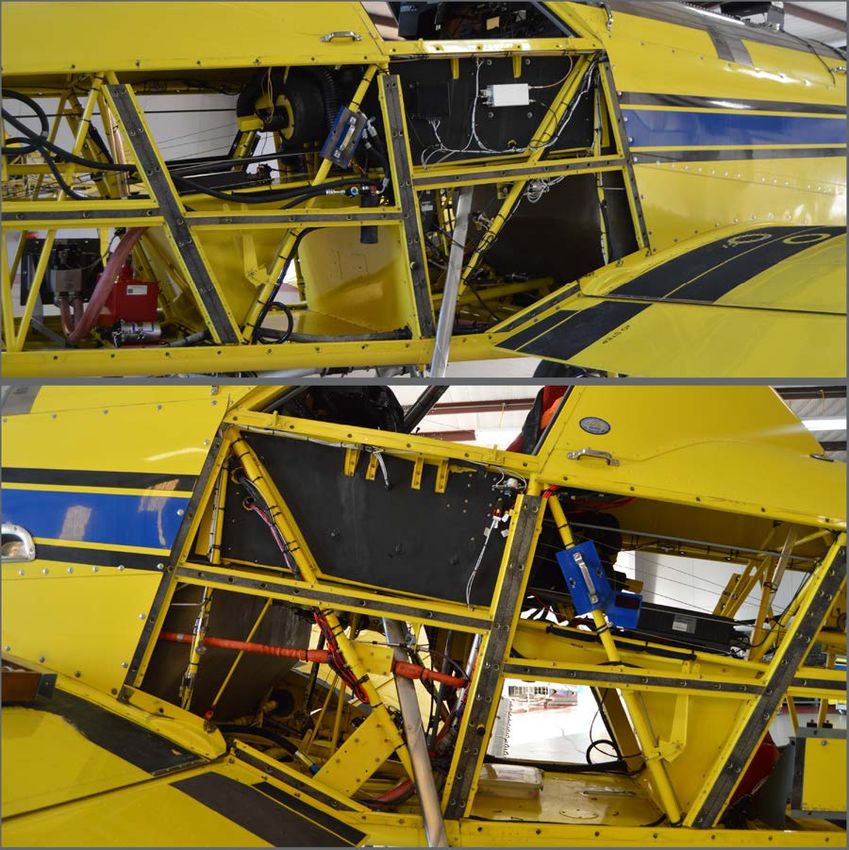
Figure 13: Access Panels Removed
To access the components, remove the panels below the cockpit and around the luggage
compartment, as shown in Figure 13.
© 2021 Capstan Ag Systems, Inc.
DRAFT 42 SwathPRO MaintenanceTM
Maintenance
Maintenance Service Intervals
Type of Service Initial Before After Bi-yearly
System Each Use Each Use
Setup
Baseline Evaluation X X
Examine the System X
Flush the System X
Clean the Nozzle Valves and Plunger Seal X
Inspection
Examine Specific System Components: X
• Gateway Hub
• Boom Hanger
• Boom Assembly
• CapView
• System Wiring
Details for each of these procedures are following in this section of the manual.
When the specified inspections in this section are accomplished, a general visual inspection of
the adjacent areas must also be accomplished while access is available. These general visual
inspections may reveal conditions that require additional maintenance activity.
Inspection items are provided for specified components and systems. The inspection program must
incorporate professionalism and good judgment by all inspection personnel. The technician must
ensure all components and systems are in good condition and maintained to the highest standards of
safety.
© 2021 Capstan Ag Systems, Inc.
DRAFT 43 SwathPRO MaintenanceTM
Maintenance
Flush the System
1. In the cockpit, turn the key on.
2. Put the Bypass Switch in the on position.
3. Push the spray handle down.
Figure 14: Connect Water Line
4. Use one of the camlock fittings (Figure 14, Item 1), located at the end of each boom, to attach a
water line (Figure 14, Item 2) that can build more than 5 psi inside of the boom.
5. Run water through the booms until clean.
© 2021 Capstan Ag Systems, Inc.
DRAFT 44 SwathPRO MaintenanceTM
Maintenance
Baseline Evaluation Process
1. Make sure that the voltage readings are correct.
For more information, see:
• CapView Battery Voltage Test
• Do a Check of the System Load Capacity
• VCM Voltage Test
• Pressure Sensor Signal Test
2. Do a visual check of all wire connections, harnesses, and connectors. Make sure that there are
no loose, broken, or damaged parts.
3. Compare the current settings with those recorded in the manual during setup.
4. Repair or replace any damaged components.
5. Do the system tests.
For more information, see:
• System Dry Tests
• System Wet Test
Examine the System
Before each use visually examine the SwathPRO™ system for visible issues.
• Remove the access panels to get access to the system components.
• Visually examine the hoses and harnesses for cuts, nicks, or abrasions before each use.
Replace any damaged parts immediately.
• Make sure that all hoses and harnesses are secure.
• Do a check for loose hoses, mounting hardware, and other components. Tighten if necessary.
• Do a check of the nozzles. Find and fix any leakage problems.
© 2021 Capstan Ag Systems, Inc.
DRAFT 45 SwathPRO MaintenanceTM
Maintenance
Examine Specific System Components
Examine the Harnesses
While inspecting the VCM harness assembly, also do a check of attaching structure for damage or
corrosion and hardware for looseness, damage, and security.
1. In the cockpit, power off the SwathPRO™ system.
2. Make sure that the main power disconnect is off.
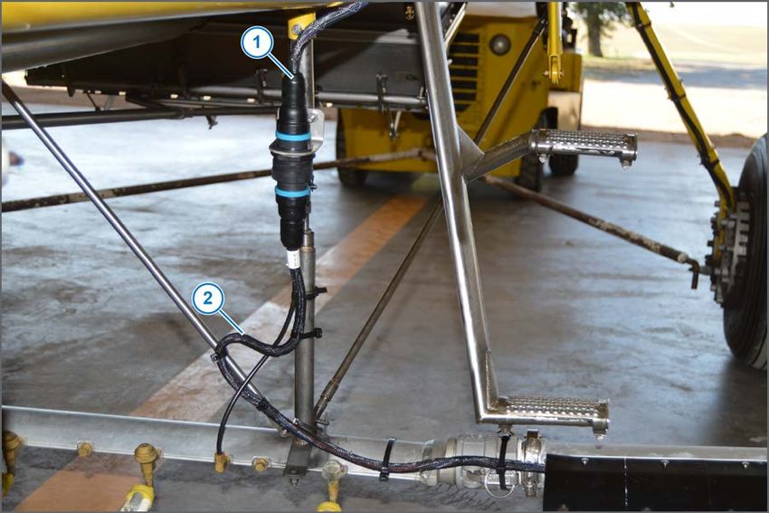
Figure 15: Boom Control Extension Harness Connector
3. On each side of the aircraft, examine the Gateway boom control extension harness (Figure 15,
Item 1), VCM harness (Figure 15, Item 2), and connectors for damage or corrosion.
4. Replace as necessary.
5. Examine the attaching structure for damage or corrosion and hardware for looseness, damage,
and security.
© 2021 Capstan Ag Systems, Inc.
DRAFT 46 SwathPRO MaintenanceTM
Maintenance
Figure 16: Shell Removal and Examine Harnesses
6. On the SwathPRO™ booms, loosen the ¼ turn screws (Figure 16, Item 1) on the top and bottom
of each shell (Figure 16, Item 2) that you want to remove.
7. Remove any tips that will not allow the shell to slide off of the tip.
Example: deflection adapters, CP nozzles, etc.
8. Remove the shells by pulling the edges (Figure 16, Item 3) to get out of the groove (Figure 16,
Item 4) and spreading them apart to get over the coil assembly.
9. Examine the harnesses (Figure 16, Item 5) for damage or wear.
10. Replace any harnesses, as necessary.
11. Examine the attaching structure for damage or corrosion and hardware for looseness, damage,
and security.
© 2021 Capstan Ag Systems, Inc.
DRAFT 47 SwathPRO MaintenanceTM
Maintenance
Remove a VCM Harness Assembly
1. In the cockpit, power the SwathPRO™ system down
2. Make sure that the main power disconnect is off.
Figure 17: Shell Removal and Disconnect the Valve Connector
3. On the SwathPRO™ booms, loosen the ¼ turn screws (Figure 17, Item 1) on the top and bottom
of each shell (Figure 17, Item 2) that is on the VCM assembly that needs to be replaced.
Depending on the system configuration, there can be up to nine shells outboard of the VCM, six
shells inboard of the VCM, and the VCM shell to remove.
4. Remove any tips that will not allow the shell to slide off of the tip.
Example: deflection adapters, CP nozzles, etc.
5. Remove the shells by pulling the edges (Figure 17, Item 3) to get out of the groove (Figure 17,
Item 4) and spreading them apart to get over the coil assembly.
6. Disconnect all 2-pin DTM connectors (Figure 17, Item 5) at each valve on the harness being
replaced.
© 2021 Capstan Ag Systems, Inc.
DRAFT 48 SwathPRO MaintenanceTM
Maintenance
Figure 18: VCM Harness Assembly Removal
7. Disconnect the 6-pin power connector (Figure 18, Item 1), located near the VCM (Figure 18, Item
2).
8. Remove the harness (Figure 18, Item 3) from under the guides (Figure 18, Item 4) on the boom.
9. Remove the VCM harness assembly from the boom.
© 2021 Capstan Ag Systems, Inc.
DRAFT 49 SwathPRO MaintenanceTM
Maintenance
Install a VCM Harness Assembly
Figure 19: VCM Harness Assembly Install
1. Lay the new VCM harness assembly (Figure 19, Item 1) along the boom (Figure 19, Item 2) like
the old harness was positioned.
2. Hook the harness into the clamps (Figure 19, Item 3) on the boom.
3. Connect the 6-pin power connector (Figure 19, Item 4) located near the VCM (Figure 19, Item 5).
4. Connect all of the 2-pin DTM connectors (Figure 19, Item 6) at each valve.
• On a 19 ft boom, the last 2-pin connector on the outboard side will need a dust plug
installed.
• On a 17 ft boom, the last three 2-pin connectors on the outboard side will need a dust
plug installed.
© 2021 Capstan Ag Systems, Inc.
DRAFT 50 SwathPRO MaintenanceTM
Maintenance
Figure 20: Shell Installation
5. Install all of the shells (Figure 20, Item 1) that go over the valve assemblies.
6. Install the VCM shell (Figure 20, Item 2) over the new VCM.
7. Tighten all of the ¼ turn fasteners on each shell (Figure 20, Item 3) on the top and bottom of the
booms.
8. Install any tips and deflectors that were removed.
9. Power the SwathPRO™ system up.
10. Take pictures of your setting screens.
11. Do the factory reset procedure.
For more information, see Do the Factory Reset Procedure.
12. Do the location setup procedure.
For more information, see Do the Location Setup Procedure.
13. Install the desired profiles.
For more information, see Upload a Profile to the CapView.
© 2021 Capstan Ag Systems, Inc.
DRAFT 51 SwathPRO MaintenanceTM
Maintenance
Nozzle Valves
Plugged nozzle valves can be classified into two categories:
• Plunger blockage
• Plunger stuck
Plunger blockage results when larger debris catches between the orifice and plunger seal. This is the
smallest flow passage within the nozzle valve.
Stuck plungers result when smaller debris collects around the barrel of the plunger and binds the
plunger in place. Symptoms of a blocked or stuck plunger are:
• Constant application
• Leaking when the nozzle is shut off
• No application
Note: Pinched or split O-rings will also cause nozzles to drip when shutoff.
Note: Operating a plugged nozzle valve for extended periods of time may result in a nozzle valve coil
failure. Immediately clean any plugged nozzle valves.
Clean the Nozzle Valve(s)
Warning: Chemical residue may be present. Always use proper personal equipment to avoid
personal injury.
Figure 21: Remove Valve Assembly
1. Release pressure from the system before servicing.
2. Clean the system before installation or service of the fittings, hoses, valves, or nozzles.
3. Loosen the quarter-turn fasteners (Figure 21, Item 1) on the top and bottom of each shell.
4. Remove the shell (Figure 21, Item 2).
5. Disconnect the coil (Figure 21, Item 3) from the harness (Figure 21, Item 4).
6. Unscrew the flynut (Figure 21, Item 5) to remove the valve assembly from the adapter.
© 2021 Capstan Ag Systems, Inc.
DRAFT 52 SwathPRO MaintenanceTM
Maintenance
Figure 22: Removal Tool—Valve Body from Flynut Removal
7. Use the removal tool (Figure 22, Item 1) to remove the valve body (Figure 22, Item 2) from the
flynut (Figure 22, Item 3).
Figure 23: Check Valve Assembly Parts
8. Remove the plunger (Figure 23, Item 1) from the coil.
9. Examine the O-rings (Figure 23, Item 2) on the coil.
10. Examine the O-rings (Figure 23, Item 3) on the valve body.
11. Wash the nozzle valve components to remove any debris.
12. Examine the plunger for wear or damage.
13. If there is wear or damage to the plunger, replace the plunger.
14. Examine the valve body.
Make sure that the orifice is not plugged with debris, worn, or damaged.
15. If there is wear or damage to the orifice, replace the valve body.
16. Wash the nozzle body components to remove any debris.
Important: Do not use brake cleaner, or the seal will be damaged.
Important: During installation, apply 40 in lbs of torque to the coil when it threads into the valve
body to properly seat the O-ring.
© 2021 Capstan Ag Systems, Inc.
DRAFT 53 SwathPRO MaintenanceYou can also read