UCPE Networking DIAG OS Guide - April 2020 - Dell
←
→
Page content transcription
If your browser does not render page correctly, please read the page content below
uCPE Networking DIAG OS Guide
April 2020
Notes, cautions, and warnings

    NOTE: A NOTE indicates important information that helps you make better use of your product.

    CAUTION: A CAUTION indicates either potential damage to hardware or loss of data and tells you how to avoid the
    problem.

    WARNING: A WARNING indicates a potential for property damage, personal injury, or death.

© 2018 - 2019 Dell Inc. or its subsidiaries. All rights reserved. Dell, EMC, and other trademarks are trademarks of Dell Inc. or its
subsidiaries. Other trademarks may be trademarks of their respective owners.

2020 - 04

Rev. A04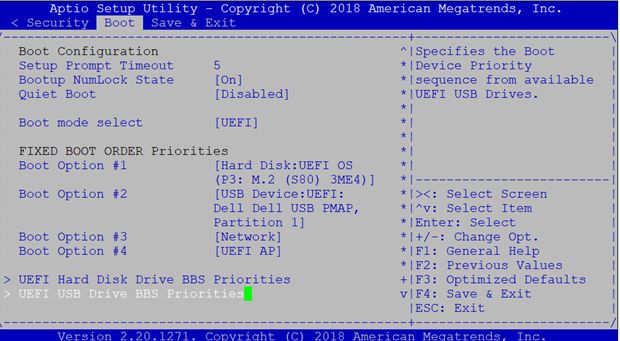
Contents

1 About this guide........................................................................................................................... 4
   Notices.................................................................................................................................................................................... 4
   Related documents................................................................................................................................................................4

2 BIOS setup and configuration........................................................................................................5
   Power on VEP4600 .......................................................................................................................................................5
   Create a serial console connection ..........................................................................................................5
   BIOS access process.............................................................................................................................................................6

3 Dell EMC DIAG OS........................................................................................................................9
   View DIAG versions............................................................................................................................................................... 9

4 Restore to Manufacture DIAG OS ....................................................................................... 10

5 Dell EMC DIAG OS tools.............................................................................................................. 16
   edatool.............................................................................................................................................................................. 16
   cputool.............................................................................................................................................................................. 19
   eepromtool....................................................................................................................................................................... 21
   ethtool..............................................................................................................................................................................24
   fantool...................................................................................................................................................................................25
   flashrom........................................................................................................................................................................... 28
   gpiotool........................................................................................................................................................................... 28
   i2ctool..............................................................................................................................................................................29
   ledtool..............................................................................................................................................................................32
   lpctool..............................................................................................................................................................................34
   memtool..............................................................................................................................................................................35
   nvramtool.........................................................................................................................................................................39
   pcitool..............................................................................................................................................................................40
   phytool..............................................................................................................................................................................44
   pltool................................................................................................................................................................................ 46
   psutool..............................................................................................................................................................................48
   rtctool..............................................................................................................................................................................49
   storagetool................................................................................................................................................................... 50
   temptool........................................................................................................................................................................... 55
   updatetool...................................................................................................................................................................... 56
   Diagnostic package............................................................................................................................................................. 57

6 Dell EMC support....................................................................................................................... 58

                                                                                                                                                                  Contents                   3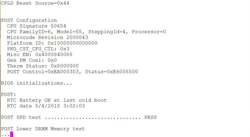
1
                                                                                     About this guide
Notices
    CAUTION: To avoid electrostatic discharge (ESD) damage, wear grounding wrist straps when handling this equipment.

    NOTE: Only trained and qualified personnel can install this equipment. Read this guide before you install and power up
    this equipment. This equipment contains two power cords. Disconnect both power cords before servicing.

    NOTE: This equipment contains optical transceivers, which comply with the limits of Class 1 laser radiation.

    Figure 1. Class 1 laser product tag

    NOTE: When no cable is connected, visible and invisible laser radiation may be emitted from the aperture of the optical
    transceiver ports. Avoid exposure to laser radiation and do not stare into open apertures.

Related documents
For more information about your Open Networking (-ON) platform, see the following documents:
•   Dell EMC Getting Started Guide or Dell EMC Setup Guide
•   Dell EMC Installation Guide
•   Dell EMC Release Notes

4        About this guide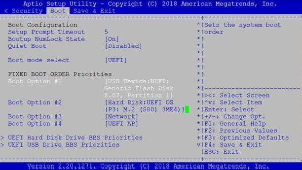
2
                                                 BIOS setup and configuration
This section describes how to access the BIOS setup and configuration screen on your system.
Access the BIOS setup and configuration screen from the command prompt. Ensure that your TFTP server is reachable over your
network.

    NOTE: The following output examples are for reference only; your output may vary.

    NOTE: The management port IP, FTP server IP address, MAC address, and user-id shown are for illustration purpose
    only. Use your system’s applicable values.

Topics:
•   Power on VEP4600
•   Create a serial console connection
•   BIOS access process

Power on VEP4600
Plug in a power cord to the back of VEP4600 platform. The platform starts to power up immediately.

Create a serial console connection
To establish a console connection use a universal serial bus (USB)-to-RS-232 connection from a USB port to a VEP4600 console port.

    NOTE: Use a 115200 baud rate.

                                                                                               BIOS setup and configuration          5
Figure 2. puTTY 115200 baud rate setup
BIOS access process
1. Press the delete button after the POST Lower DRAM Memory test appears on the screen.
Continue pressing the delete button to progress to the BIOS setup and configuration screen.
NOTE: If the BIOS setup and configuration screen window passes, power off and power on the platform again to
restart the boot up process.
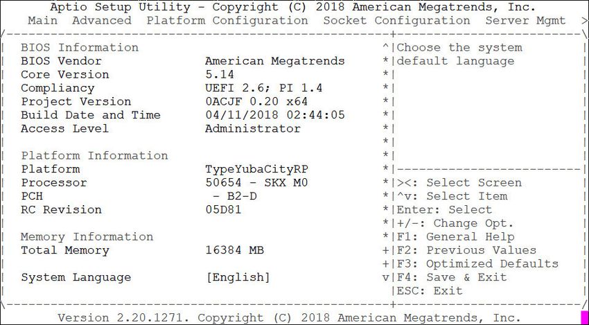
6 BIOS setup and configurationFigure 3. Initial boot up screen
Figure 4. Boot up screen
BIOS setup and configuration 7Figure 5. BIOS setup and configuration screen 8 BIOS setup and configuration
3
                                                                               Dell EMC DIAG OS
The following describes the Dell EMC diagnostics operating system (DIAG OS).
Topics:
•     View DIAG versions

View DIAG versions
To display the DIAG version installed in the DIAG OS, use the dpkg -l | grep dn-diags command at the root@dell-diag-
os:~ prompt.

    root@dell-diag-os:/# dpkg -l | grep dn-diags
    ii dn-diags--on.deb 1.10 amd64     Dell Diagnostics
    root@dell-diag-os:/#

                                                                                              Dell EMC DIAG OS         9
4
Restore to Manufacture DIAG OS
Manufacture DIAG OS recovery for the VEP4600 platform.
Burn DIAG OS ISO image to a bootable USB
1. Mount the USB to a Linux computer or VEP4600 with DIAG OS.
2. Log in to the Linux OS.
3. Download the DIAG OS ISO image to the Linux computer using TCP, SCP, or a similar protocol.
4. Use the following DD (data duplicator) CLI (command line interface) Linux command to copy the DIAG OS to the USB.
dd if=onie-recovery-x86_64-dellemc_vep4600_d21xyt-r0.48.iso of=/dev/sdb bs=4M
NOTE: Use /dev/sdb, not the sdb# number even if the disk shows sdb# as one of the USB sticks plugged in.
Device Boot Start End Sectors Size Id Type
/dev/sdb1 * 7516 7899 384 192K ef EFI (FAT-12/16/32)
Configure BIOS to install DIAG OS from USB
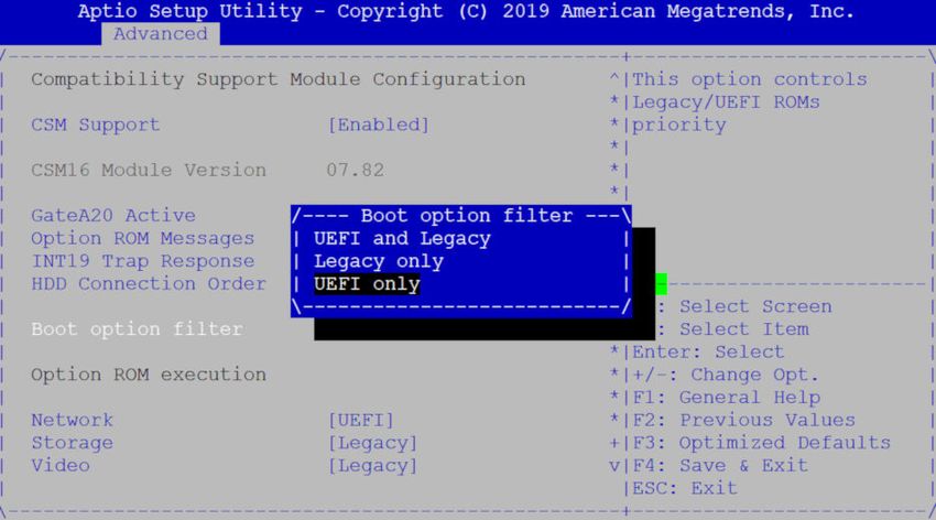
1. Boot into BIOS setting, goto Advanced, set CSM to UEFI only
Figure 6. Boot BIOS setting
2. Select the Boot menu tab.
10 Restore to Manufacture DIAG OSFigure 7. Boot menu tab
3. Select UEFI: then USB Device: to boot the DIAG OS from a USB drive.
Figure 8. DIAG OS USB to boot UEFI
Figure 9. DIAG OS USB to boot USB device
4. Verify that Boot Option #1 lists the DIAG OS USB as the boot option.
Figure 10. Boot Option #1
5. Press F4 to save and exit the utility and to start the installation.
Restore to Manufacture DIAG OS 11DIAG OS installation failure and resolution
ESXi may create a different disk partition that is not compatible with the DIAG OS. This causes the DIAG OS installation to fail and display
this error message:
ONIE: Rescue Mode ...
Platform : x86_64-dellemc_vep4600_d21xyt-r0
Version : x.xx.x.xx-x
Build Date: 2018-04-24T03:20-0700
▒[ 13.793445] ata4.00: failed to set xfermode (err_mask=0x40)
Info: Mounting kernel filesystems... done.
Info: Using eth0 MAC address: d8:9e:f3:bc:6a:a0
Info: eth0: Checking link... up.
Info: Trying DHCPv4 on interface: eth0
Warning: Unable to configure interface using DHCPv4: eth0
ONIE: Using link-local IPv4 addr: eth0: xxx.xxx.x.xxx/xx
+ cat /DiagOS_version.cfg
+ version_packed=x.xx.x.xx-x
+ ls
+ grep x.xx.x.xx-x
+ image_packed=diag-installer-x86_64-dellemc_vep4600_d21xyt-r0-x.xx.x.xx-x-2018-04-24.bin
+ [ -z diag-installer-x86_64-dellemc_vep4600_d21xyt-r0-x.xx.x.xx-x-2018-04-24.bin ]
+ echo starting to install vep4600 DiagOS
starting to install vep4600 DiagOS
+ onie-nos-install /diag-installer-x86_64-dellemc_vep4600_d21xyt-r0-x.xx.x.xx-x-2018-04-24.bin
discover: Rescue mode detected. No discover stopped.
ONIE: Executing installer: /diag-installer-x86_64-dellemc_vep4600_d21xyt-r0-x.xx.x.xx-
x-2018-04-24.bin
Ignoring Verifying image checksum ... OK.
cur_dir / archive_path /var/tmp/installer tmp_dir /tmp/tmp.XeWxoj
Preparing image archive ...sed -e '1,/^exit_marker$/d' /var/tmp/installer | tar xf - OK.
Diag-OS Installer: platform: x86_64-dellemc_vep4600_d21xyt-r0
EDA-DIAG Partiton not found.
Diag OS Installer Mode : INSTALL
Deleting partition at /dev/sdc1...
The operation has completed successfully.
Deleting partition at /dev/sdc2...
The operation has completed successfully.
Deleting partition at /dev/sdc3...
The operation has completed successfully.
Deleting partition at /dev/sdc4...
Partition number 4 out of range!
Error 0 deleting partition!
Error encountered; not saving changes.
Error: Unable to delete partition 4 on /dev/sdc
Removing /tmp/tmp.XeWxoj
Failure: Unable to install image: /diag-installer-x86_64-dellemc_vep4600_d21xyt-r0-x.xx.x.xx-
x-2018-04-24.bin
+ echo This should be not reachable unless something wrong is there!!!!!
This should be not reachable unless something wrong is there!!!!!
Starting: dropbear ssh daemon... done.
Starting: telnetd... done.
discover: Rescue mode detected. Installer disabled.
Please press Enter to activate this console.
To check the install status inspect /var/log/onie.log.
Try this: tail -f /var/log/onie.log
To resolve this issue, delete the partition completely and restart the DIAG OS installation.
1. Press Enter from the error message to get to ONIE Recovery mode.
NOTE: WARNING: Deleting the partition causes all data and the OS to be lost.
12 Restore to Manufacture DIAG OS2. Type the following then click Enter.
gdisk /dev/sdc
** Rescue Mode Enabled **
ONIE-RECOVERY:/ #
gdisk /dev/sdc
GPT fdisk (gdisk) version 0.8.8
Partition table scan:
MBR: protective
BSD: not present
APM: not present
GPT: present
Found valid GPT with protective MBR; using GPT.
3. Type o to delete the partition.
Command (? for help):
Command (? for help): o
This option deletes all partitions and creates a new protective MBR.
Proceed? (Y/N): y
Type w to write the new partition into the disk
Command (? for help): w
Final checks complete. About to write GPT data. THIS WILL OVERWRITE EXISTING
PARTITIONS!!
Do you want to proceed? (Y/N): y
OK; writing new GUID partition table (GPT) to /dev/sdc.
The operation has completed successfully.
ONIE-RECOVERY:/ #
4. Type reboot at the command prompt and restart the DIAG OS installation. A successful installation displays the following:
ONIE: Rescue Mode ...
Platform : x86_64-dellemc_vep4600_d21xyt-r0
Version : x.xx.x.xx-x
Build Date: 2018-04-24T03:20-0700
▒[ 12.771519] ata4.00: failed to set xfermode (err_mask=0x40)
Info: Mounting kernel filesystems... done.
Info: Using eth0 MAC address: d8:9e:f3:bc:6a:a0
Info: eth0: Checking link... up.
Info: Trying DHCPv4 on interface: eth0
Warning: Unable to configure interface using DHCPv4: eth0
ONIE: Using link-local IPv4 addr: eth0: 169.254.195.48/16
+ cat /DiagOS_version.cfg
+ version_packed=x.xx.x.xx-x
+ ls
+ grep x.xx.x.xx-x
+ image_packed=diag-installer-x86_64-dellemc_vep4600_d21xyt-r0-x.xx.x.xx-x-2018-04-24.bin
+ [ -z diag-installer-x86_64-dellemc_vep4600_d21xyt-r0-x.xx.x.xx-x-2018-04-24.bin ]
+ echo starting to install vep4600 DiagOS
starting to install vep4600 DiagOS
+ onie-nos-install /diag-installer-x86_64-dellemc_vep4600_d21xyt-r0-x.xx.x.xx-
x-2018-04-24.bin
discover: Rescue mode detected. No discover stopped.
ONIE: Executing installer: /diag-installer-x86_64-dellemc_vep4600_d21xyt-r0-x.xx.x.xx-
x-2018-04-24.bin
Ignoring Verifying image checksum ... OK.
cur_dir / archive_path /var/tmp/installer tmp_dir /tmp/tmp.yb6fIB
Preparing image archive ...sed -e '1,/^exit_marker$/d' /var/tmp/installer | tar xf - OK.
Diag-OS Installer: platform: x86_64-dellemc_vep4600_d21xyt-r0
EDA-DIAG Partiton not found.
Diag OS Installer Mode : INSTALL
partprobe in remove all partitions
GPT data structures destroyed! You may now partition the disk using fdisk or
Restore to Manufacture DIAG OS 13other utilities.
Creating new GPT entries.
GPT data structures destroyed! You may now partition the disk using fdisk or
other utilities.
Creating new GPT entries.
The operation has completed successfully.
The operation has completed successfully.
mkfs.fat 3.0.26 (2014-03-07)
create_grub_boot_partition finished !
Creating new diag-os partition /dev/sdc2 ...
Warning: The kernel is still using the old partition table.
The new table will be used at the next reboot.
The operation has completed successfully.
EDA-DIAG dev is /dev/sdc2
mke2fs 1.42.13 (17-May-2015)
Discarding device blocks: done
Creating filesystem with 262144 4k blocks and 65536 inodes
Filesystem UUID: c7971d6a-acb1-46be-84a2-a8d2d758139b
Superblock backups stored on blocks:
32768, 98304, 163840, 229376
Allocating group tables: done
Writing inode tables: done
Creating journal (8192 blocks): done
Writing superblocks and filesystem accounting information: done
Created filesystem on /dev/sdc2 with label EDA-DIAG
Mounted /dev/sdc2 on /tmp/tmp.iK7Bg3
Preparing /dev/sdc2 EDA-DIAG for rootfs install
untaring into /tmp/tmp.iK7Bg3
rootfs copy done
Success: Support tarball created: /tmp/tmp.iK7Bg3/onie-support.tar.bz2
Updating Grub Cfg /dev/sdc2 EDA-DIAG
Configure BIOS and boot into DIAG OS
After the DIAG OS installation completes, configure the BIOS then boot into the DIAG OS.
1. Boot into the BIOS setting.
2. Configure Boot Option #1 from the Boot Configuration screen.
Figure 11. Boot configuration screen
3. Press the F4 key to save the changes and exit the utility.
4. Confirm saving the configuration using the left and right arrow keys, and exit from the utility. Select Yes and press Enter.
14 Restore to Manufacture DIAG OSFigure 12. Save & exit
After you save the changes the log in command prompt displays.
Figure 13. Log in command prompt
5. Type to log in.
root/calvin
DIAG OS Verification
NOTE: The system shows the current version.
After DIAG OS installation, to verify the DIAG OS version, boot into boot into the DIAG OS by the following commands.
1. Log in into the DIAG OS using root as the username and calvinas the password.
2. Enter the sh_ver command.
root@dellemc-diag-os:~#sh_ver
Diag OS version VEP4600_DIAG_OS_x.xx.x.xx-x
Build date/time Tue Apr 24 00:15:20 PDT 2018
Build server netLogin-eqx-03
Build by cwang3
Kernel Info:
Linux 4.9.30 #1 SMP PREEMPT Tue Apr 24 00:12:19 PDT 2018 x86_64 GNU/Linux
Debian GNU/Linux 8 \n \l
root@dellemc-diag-os:~#
Restore to Manufacture DIAG OS 155
Dell EMC DIAG OS tools
This section describes how to use the Dell EMC diagnostics operating system (DIAG OS). The DIAG OS provides a suite of tools to help
diagnose issues seen on the system, or to run a health check to ensure that the hardware is operating properly.
Diagnostic tools
The DIAG OS uses standard Linux drivers and contains the following tools you can use to evaluate the health of your system. The tools are
packaged for both the DIAG OS, which is a simple OS of the same kernel version, and small rootfs to support the tools and drivers.
Topics:
• edatool
• cputool
• eepromtool
• ethtool
• fantool
• flashrom
• gpiotool
• i2ctool
• ledtool
• lpctool
• memtool
• nvramtool
• pcitool
• phytool
• pltool
• psutool
• rtctool
• storagetool
• temptool
• updatetool
• Diagnostic package
edatool
The edatool is included in the diagnostic tools. Use the tool to test the basic functionality of the system.
The edatool executes a script of simple commands, similar to commands in the CLI. Usually, the diagnostics tools run these types of
tests. The success or failure of these tools is reported, and at the end of the edatool run, reports the PASSED or FAILED results in a
standard format the test scripts can easily parse.
Tests
The edatool does not have a test command, but instead runs all the tests that are scripted.
CLI options
DellEmc Diag - Extended Diagnostics Application
version 1.4, x.xx.x.x-x
build, 2017/05/23,
16 Dell EMC DIAG OS toolsSyntax: edatool
Show the Help-text:=
edatool --h (or)
edatool -h
Lists tests in config files:=
edatool --list (or)
edatool -l
Config file to use for tests:=
edatool --config= (or)
edatool -f
Config file to use for extended tests:=
edatool --extended-config= (or)
edatool -X
Display test list or test result or modify test item status:=
edatool --testlist=show/result/(or)
edatool -L show/result/
Run all or selected test item in test list:=
edatool --testrun=all/ (or)
edatool --R all/
Execute repeatedly command by count:=
edatool --iteration=max/ [option1] [option2]... (or)
edatool -I max/ [option1] [option2]...
Usage:=
-h, --h Show the help text
-l, --list List the understood TLV codes and names
-I, --iteration= Iteration command execution
-L, --testlist= Test list status
-R, --testrun= Run test item
-f, --config= To specify the location of the config file e.g. /etc/dn/diag/
-X, --extended-config= Config file to use for extended tests
Output
root@dell-diag-os:~# edatool
*****************************
* Diagnostics Application *
*****************************
Dell-EMC Diag edatool version 1.4, package x.xx.x.x 2016/11/21
Dell-EMC Diag cputool - version 1.1 package x.xx.x.x 2016/11/21
Dell-EMC Diag fantool - version 1.5 package x.xx.x.x 2016/11/21
Dell-EMC Diag gpiotool - version 1.4 package x.xx.x.x 2016/11/21
Dell-EMC Diag i2ctool - version 1.5 package x.xx.x.x 2016/11/21
Dell-EMC Diag ledtool - version 1.0 package x.xx.x.x 2016/11/21
Dell-EMC Diag lpctool - version 1.0 package x.xx.x.x 2016/11/21
Dell-EMC Diag memtool - version 1.5 package x.xx.x.x 2016/11/21
Dell-EMC Diag nputool - version 1.0 sdk-6.5.5 package x.xx.x.x 2016/11/21
Dell-EMC Diag nvramtool - version 1.5 package x.xx.x.x 2016/11/21
Dell-EMC Diag opticstool - version 1.0 package x.xx.x.x 2016/11/21
Dell-EMC Diag pcitool - version 1.5 package x.xx.x.x 2016/11/21
Dell-EMC Diag pltool - version 1.5 package x.xx.x.x 2016/11/21
Dell-EMC Diag psutool - version 1.4 package x.xx.x.x 2016/11/21
Dell-EMC Diag rtctool - version 1.1 package x.xx.x.x 2016/11/21
Dell-EMC Diag smbiostool - version 1.2 package x.xx.x.x 2016/11/21
Dell-EMC Diag storagetool - version 1.1 package x.xx.x.x 2016/11/21
Dell-EMC Diag temptool - version 1.4 package x.xx.x.x 2016/11/21
Testing PCI devices:
+ Checking PCI 00:00.0, ID=1f0c8086 ....................... Passed
+ Checking PCI 00:01.0, ID=1f108086 ....................... Passed
+ Checking PCI 00:02.0, ID=1f118086 ....................... Passed
+ Checking PCI 00:03.0, ID=1f128086 ....................... Passed
+ Checking PCI 00:0e.0, ID=1f148086 ....................... Passed
+ Checking PCI 00:0f.0, ID=1f168086 ....................... Passed
+ Checking PCI 00:13.0, ID=1f158086 ....................... Passed
+ Checking PCI 00:14.0, ID=1f418086 ....................... Passed
+ Checking PCI 00:14.1, ID=1f418086 ....................... Passed
+ Checking PCI 00:14.2, ID=1f418086 ....................... Passed
+ Checking PCI 00:16.0, ID=1f2c8086 ....................... Passed
Dell EMC DIAG OS tools 17+ Checking PCI 00:17.0, ID=1f228086 ....................... Passed + Checking PCI 00:18.0, ID=1f328086 ....................... Passed + Checking PCI 00:1f.0, ID=1f388086 ....................... Passed + Checking PCI 00:1f.3, ID=1f3c8086 ....................... Passed + Checking PCI 01:00.0, ID=837514e4 ....................... Passed + Checking PCI 01:00.1, ID=837514e4 ....................... Passed PCI devices: Overall test results --------------------- >>> Passed Testing I2C devices: Checking I2C devices on bus 0: + Checking Clock GEN 0x69 ..... Passed + Checking SPD0 0x50 ..... Passed Checking I2C devices on bus 1: + Checking CPU Board I2C Mux 0x70 ..... Passed + Checking CPU Board EEPROM1 0x53 ..... Passed + Checking CPU Board EEPROM2 0x57 ..... Passed + Checking Switch Brd EEPROM 0x50 ..... Passed + Checking CPLD2 0x3e ..... Passed + Checking CPLD3 0x3e ..... Passed + Checking CPLD4 0x3e ..... Passed + Checking SFP+ 1 0x50 ..... Passed + Checking SFP+ 2 0x50 ..... Passed + Checking SFP+ 3 0x50 ..... Passed + Checking SFP+ 4 0x50 ..... Passed + Checking SFP+ 5 0x50 ..... Passed + Checking SFP+ 6 0x50 ..... Passed + Checking SFP+ 7 0x50 ..... Passed + Checking SFP+ 8 0x50 ..... Passed + Checking SFP+ 9 0x50 ..... Passed + Checking SFP+ 10 0x50 ..... Passed + Checking SFP+ 11 0x50 ..... Passed + Checking SFP+ 12 0x50 ..... Passed + Checking SFP+ 13 0x50 ..... Passed + Checking SFP+ 14 0x50 ..... Passed + Checking SFP+ 15 0x50 ..... Passed + Checking SFP+ 16 0x50 ..... Passed + Checking SFP+ 17 0x50 ..... Passed + Checking SFP+ 18 0x50 ..... Passed + Checking SFP+ 19 0x50 ..... Passed + Checking SFP+ 20 0x50 ..... Passed + Checking SFP+ 21 0x50 ..... Passed 18 Dell EMC DIAG OS tools
+ Checking SFP+ 22                                0x50     ..... Passed

    + Checking SFP+ 23                                0x50     ..... Passed

    + Checking SFP+ 24                                0x50     ..... Passed

    + Checking SFP+ 25                                0x50     ..... Passed

    + Checking SFP+ 26                                0x50     ..... Passed

    + Checking SFP+ 27                                0x50     ..... Passed

    + Checking SFP+ 28                                0x50     ..... Passed

    + Checking SFP+ 29                                0x50     ..... Passed

    + Checking SFP+ 30                                0x50     ..... Passed

    + Checking SFP+ 31                                0x50     ..... Passed

    + Checking SFP+ 32                                0x50     ..... Passed

    + Checking SFP+ 33                                0x50     ..... Passed

    + Checking SFP+ 34                                0x50     ..... Passed

    + Checking SFP+ 35                                0x50     .....

Verbose mode
Use the following steps to enable and set the verbose level.
1. Set the Verbose level with a value of 0 to 3 using bits 4 and 5 of the EDA control reg (0x55).
     For example, to set the verbose level to 2, set bit 5 to 1 (5=1) and bit 4 to 0 (4=0).
     root@dellemc-diag-os:~# nvramtool --write --reg=0x55 --val=0x25
   The value is written in hexadecimal. The xx10x1xx shows the bit positions of 2, 4&5, and bit 0 on the right.
2. Enable Verbose mode by setting bit 2 of the same reg to 1.
         NOTE: If you disable Verbose mode, or bit 2 of reg 0x55 is set to 0, the default verbosity level is 0/zero.

EDA control reg (0x55):
•    5:4—EDA Verbose Level = 0/1/2/3 or verbosity level 0, 1, 2, or 3.
•    3—EDA Extended Tests
•    2—EDA Verbose Mode = 0/1 (0=disabled; 1=enabled)
•    1—EDA Stop on Error
•    0—EDA Enable
      NOTE: If you do not need the Verbose mode settings to persist through reboots, you can use the environment variable
      method to enable Verbose Mode.

       export VERB_LEVEL=

      To clear the environment variable, use the unset VERB_LEVEL command.

cputool
The cputool displays the CPU information, reads and writes of the MSR and the LPC bus.

Tests
There are no defined tests with the cputool.

                                                                                                     Dell EMC DIAG OS tools   19
CLI options
root@dellemc-diag-os:~# cputool
DellEmc Diag - Cpu Tool
version 1.1, x.xx.x.x-x
build, 2017/05/23,
Syntax: cputool
Show the help-text:=
cputool --h (or)
cputool -h
Display the CPU info using CPU-ID:
cputool --cpuid[=--option] (or)
cputool -i [option]
Display the CPU info using x86info:=
cputool --x86info[=--option] (or)
cputool -x [option]
Read CPU register:=
cputool --readmsr --cpu= --reg= (or)
cputool -r -n -R
Write CPU register:=
cputool --writemsr --cpu= --reg= --val= (or)
cputool -w -R -V
Execute repeatedly command by count:=
cputool --iteration=max/ [option1] [option2]... (or)
cputool -I max/ [option1] [option2]...
Read the specified regiser in LPC bus:=
cputool --readlpc --reg= --size= (or)
cputool -d -R -Z
Write the specified regiser in LPC bus:=
cputool --writelpc --reg= --val= --size= (or)
cputool -W -R -V -Z
Usage:=
-h, --h Show the help text
-i, --cpuid CPU-Id
-x, --x86info x86 info
-r, --readmsr Read operation
-w, --writemsr Write operation
-n, --cpu= CPU
-R, --reg= Register
-V, --val= Value to be set
-Z, --size= Size
-I, --iteration= Iteration command execution
-d, --readlpc Read from LPC bus
-W, --writelpc Write to LPC bus
Output
root@dell-diag-os:/# cputool --h
Dell Diag - Cpu Tool
version 1.1, x.xx.x.x
build, 2016/08/12,
Syntax: cputool
Show the help-text:=
cputool --h (or)
cputool -h
Display the CPU info using CPU-ID:
cputool --cpuid[=--option] (or)
cputool -i [option]
Display the CPU info using x86info:=
cputool --x86info[=--option] (or)
cputool -x [option]
Read CPU register:=
cputool --readmsr --cpu= --reg= (or)
cputool -r -n -R
Write CPU register:=
cputool --writemsr --cpu= --reg= --val= (or)
cputool -w -R -V
20 Dell EMC DIAG OS toolsRead the specified regiser in LPC bus:=
cputool --readlpc --reg= --size= (or)
cputool -d -R -Z
Write the specified regiser in LPC bus:=
cputool --writelpc --reg= --val= --size= (or)
cputool -W -R -V -Z
Usage:=
-h, --h Show the help text
-i, --cpuid CPU-Id
-x, --x86info x86 info
-r, --readmsr Read operation
-w, --writemsr Write operation
-n, --cpu= CPU
-R, --reg= Register
-V, --val= Value to be set
-Z, --size= Size
-d, --readlpc Read from LPC bus
-W, --writelpc Write to LPC bus
root@dell-diag-os:/#
root@dell-diag-os:/# cputool --x86info
x86info v1.30. Dave Jones 2001-2011
Feedback to .
Found 4 identical CPUs
Extended Family: 0 Extended Model: 4 Family: 6 Model: 77 Stepping: 8
Type: 0 (Original OEM)
CPU Model (x86info's best guess): Unknown model.
Processor name string (BIOS programmed): Intel(R) Atom(TM) CPU C2538 @ 2.40GHz
Total processor threads: 4
This system has 1 dual-core processor with hyper-threading (2 threads per core) running at an
estimated 2.40GHz
root@dell-diag-os:/#
eepromtool
To program FRU format EEPROMS, use the eepromtool. You can also use the eepromtool to show all the FRU-formatted EEPROM
contents or show specific EEPROM content by specifying the EEPROM type.
Tests
NOTE: The eepromtool tool is used during manufacturing to program FRU data.
CAUTION: The eepromtool tool should only be used to read an EEPROM device.
The following command line options are valid cases for running eepromtool in Azul.
1. To list the supported eeprom devices type eepromtool -L
root@dellemc-diag-os:~# eepromtool -L
MC1EEPROM
MC2EEPROM
PSU1EEPROM
PSU2EEPROM
FAN1EEPROM
FAN2EEPROM
FAN3EEPROM
FAN4EEPROM
FAN5EEPROM
IDEEPROM
root@dellemc-diag-os:~#
2. To show a device content type eepromtool -P -x
root@dellemc-diag-os:~# eepromtool -P PSU1EEPROM -x
Board Mfg Date : Mon Mar 19 03:40:00 2018
Board Mfg : DELL
Board Product : PWR SPLY,495W,RDNT,DELTA
Board Serial : CNDED0083H0T94
Dell EMC DIAG OS tools 21Board Part Number : 0GRTNKA02
root@dellemc-diag-os:~#
a.
The test option in EEPROM devices allows you to verify the MAC address. Use this test for MAC address consistency.
CLI options
DellEmc Diag - Eeprom Tool
version 1.5, x.xx.x.x-x
build, 2017/05/23,
Syntax:= eepromtool
Display help-text:=
eepromtool --help (or)
eepromtool -h
List the understood TLV codes and names:=
eepromtool --list (or)
eepromtool -l
List all eeprom devices:=
eepromtool --listdevices (or)
eepromtool -L
Dump the PSU eeprom:=
eepromtool --psueepromdump (or)
eepromtool -m
Dump the FAN eeprom:=
eepromtool --faneepromdump (or)
eepromtool -F
Show the EEPROM data:=
eepromtool --eeprom= --show (or)
eepromtool -P -x
Reset the EEPROM data:=
eepromtool --eeprom= --erase (or)
eepromtool -P -e
Verify the MAC address in system-eeprom and mac-eeprom:=
eepromtool --eeprom= --test (or)
eepromtool -P -t
Look up a TLV by code and write the value to stdout:=
eepromtool --eeprom= --get (or)
eepromtool -P -g
Execute repeatedly command by count:=
eepromtool --iteration=max/ [option1] [option2]... (or)
eepromtool -I max/ [option1] [option2]...
Set a TLV code to a value:=
eepromtool --eeprom= --set =,=...(or)
eepromtool -P -s =,=...
Usage:=
-h, --h Show the help text
-l, --list List the understood TLV codes and names
-L, --listdevices List all EEPROM devices
-m, --psueepromdump Dump the PSU EEPROM
-F, --faneepromdump Dump the FAN EEPROM
-P, --eeprom= EEPROM type
-x, --show Show operation
-e, --erase Erase operation
-t, --test Test using the pre-programmed configuration or use supplied config
-I, --iteration= Iteration command execution
-g, --get Get operation
-s, --set Set operation
Output
root@dell-diag-os:/opt/ngos/bin# eepromtool --list
TLV Code TLV Name
======== =================
0x21 Product Name
22 Dell EMC DIAG OS tools0x22 Part Number
0x23 Serial Number
0x24 Base MAC Address
0x25 Manufacture Date
0x26 Device Version
0x27 Label Revision
0x28 Platform Name
0x29 Loader Version
0x2a MAC Addresses
0x2b Manufacturer
0x2c Country Code
0x2d Vendor Name
0x2e Diag Version
0x2f Service Tag
0xfd Vendor Extension
0xfe CRC-32
root@dell-diag-os:/opt/ngos/bin# eepromtool --listdevices
CPUEEPROM1
CPUEEPROM2
CPUEEPROM3
CPUEEPROM4
CPUEEPROM5
CPUEEPROM6
CPUEEPROM7
CPUEEPROM8
FAN1EEPROM
FAN2EEPROM
FAN3EEPROM
FAN4EEPROM
FAN5EEPROM
SwitchEEPROM
root@dell-diag-os:/# eepromtool --psueepromdump
************PSU1_CountryCode*************
Registers 0x24a - 0x24b
CN
************PSU1_DellPartNumber*************
Registers 0x24c - 0x251
02RPHX
************PSU1_MfgID*************
Registers 0x252 - 0x256
17972
************PSU1_MfgDate*************
Registers 0x257 - 0x25e
151117
************PSU1_SerialNo*************
Registers 0x25f - 0x262
01CG
************PSU1_ServiceTag*************
Registers 0x263 - 0x269
************PSU1_LabelRevision*************
Registers 0x26a - 0x26c
A00
************PSU2_CountryCode*************
Registers 0x283 - 0x284
CN
************PSU2_DellPartNumber*************
Registers 0x285 - 0x28a
02RPHX
************PSU2_MfgID*************
Registers 0x28b - 0x28f
17972
************PSU2_MfgDate*************
Registers 0x290 - 0x297
151117
************PSU2_SerialNo*************
Registers 0x298 - 0x29b
015F
************PSU2_ServiceTag*************
Registers 0x29c - 0x2a2
************PSU2_LabelRevision*************
Registers 0x2a3 - 0x2a5
A00
root@dell-diag-os:/#
Dell EMC DIAG OS tools 23root@dell-diag-os:/opt/ngos/bin# root@dell-diag-os:/opt/ngos/bin# eepromtool --eeprom=cpueeprom2 --set 0x21='cpu2' Notice: Invalid TLV checksum found. Using default contents. Adding TLV 0x21: Product Name Programming passed. TlvInfo Header: Id String: TlvInfo Version: 1 Total Length: 12 TLV Name Code Len Value -------------------- ---- --- ----- Product Name 0x21 4 cpu2 CRC-32 0xFE 4 0x338B2B86 Checksum is valid. root@dell-diag-os:/opt/ngos/bin# root@dell-diag-os:/opt/ngos/bin# eepromtool --eeprom=cpueeprom2 --get 0x21 cpu2 root@dell-diag-os:/opt/ngos/bin# root@dell-diag-os:/opt/ngos/bin# eepromtool --eeprom=cpueeprom2 --show TlvInfo Header: Id String: TlvInfo Version: 1 Total Length: 12 TLV Name Code Len Value -------------------- ---- --- ----- Product Name 0x21 4 cpu2 CRC-32 0xFE 4 0x338B2B86 Checksum is valid. root@dell-diag-os:/opt/ngos/bin# root@dell-diag-os:/opt/ngos/bin# eepromtool --eeprom=cpueeprom1 --erase Programming passed. EEPROM does not contain data in a valid TlvInfo format. root@dell-diag-os:/opt/ngos/bin# eepromtool --eeprom=cpueeprom1 --show Notice: Invalid TLV header found. Using default contents. Notice: Invalid TLV checksum found. Using default contents. TlvInfo Header: Id String: TlvInfo Version: 1 Total Length: 6 TLV Name Code Len Value -------------------- ---- --- ----- CRC-32 0xFE 4 0xD4431C18 Checksum is valid. root@dell-diag-os:/opt/ngos/bin# ethtool To control and query network drivers and hardware use the ethtool. Tests root@dellemc-diag-os:/opt/dellemc/diag/bin# ethtool -t ethx CLI options ethtool -h|--help ethtool --version ethtool -a|--show-pause devname ethtool -A|--pause devname [autoneg on|off] [rx on|off] [tx on|off] ethtool -c|--show-coalesce devname ethtool -C|--coalesce devname [adaptive-rx on|off] [adaptive-tx on|off] [rx-usecs N] [rx- frames N] [rx-usecs-irq N] [rx-frames-irq N] [tx-usecs N] [tx-frames N] [tx-usecs-irq N] [tx- frames-irq N] [stats-block-usecs N] [pkt-rate-low N] [rx-usecs-low N] [rx-frames-low N] [tx- usecs-low N] [tx-frames-low N] [pkt-rate-high N] [rx-usecs-high N] [rx-frames-high N] [tx- usecs-high N] [tx-frames-high N] [sample-interval N] ethtool -g|--show-ring devname 24 Dell EMC DIAG OS tools
ethtool -G|--set-ring devname [rx N] [rx-mini N] [rx-jumbo N] [tx N]
 ethtool -i|--driver devname
 ethtool -d|--register-dump devname [raw on|off] [hex on|off] [file name]
 ethtool -e|--eeprom-dump devname [raw on|off] [offset N] [length N]
 ethtool -E|--change-eeprom devname [magic N] [offset N] [length N] [value N]
 ethtool -k|--show-features|--show-offload devname
 ethtool -K|--features|--offload devname feature on|off ...
 ethtool -p|--identify devname [N]
 ethtool -P|--show-permaddr devname
 ethtool -r|--negotiate devname
 ethtool -S|--statistics devname
 ethtool -t|--test devname [offline|online|external_lb]
 ethtool -s devname speed N [duplex half|full] [port tp|aui|bnc|mii] [autoneg on|off]
 [advertise N] [phyad N] [xcvr internal|external] [wol p|u|m|b|a|g|s|d...] [sopass
 xx:yy:zz:aa:bb:cc] [msglvl N | msglvl type on|off ...]
 ethtool -n|-u|--show-nfc|--show-ntuple devname [ rx-flow-hash tcp4|udp4|ah4|esp4|sctp4|tcp6|
 udp6|ah6|esp6|sctp6 |
 rule N ]
 ethtool -N|-U|--config-nfc|--config-ntuple devname rx-flow-hash tcp4|udp4|ah4|esp4|sctp4|tcp6|
 udp6|ah6|esp6|sctp6 m|v|t|s|d|f|n|r... |
 flow-type ether|ip4|tcp4|udp4|sctp4|ah4|esp4 [src xx:yy:zz:aa:bb:cc [m xx:yy:zz:aa:bb:cc]]
 [dst xx:yy:zz:aa:bb:cc [m xx:yy:zz:aa:bb:cc]] [proto N [m N]] [src-ip x.x.x.x [m x.x.x.x]]
 [dst-ip x.x.x.x [m x.x.x.x]] [tos N [m N]] [l4proto N [m N]] [src-port N [m N]] [dst-port N
 [m N]] [spi N [m N]] [l4data N [m N]] [vlan-etype N [m N]] [vlan N [m N]] [user-def N [m N]]
 [action N] [loc N] |
 delete N
 ethtool -w|--get-dump devname [data filename]
 ethtool -W|--set-dump devname N
 ethtool -T|--show-time-stamping devname
 ethtool -x|--show-rxfh-indir devname
 ethtool -X|--set-rxfh-indir devname [ equal N | weight W0 W1 ... ]
 ethtool -f|--flash devname FILE [N]
 ethtool -l|--show-channels devname
 ethtool -L|--set-channels devname [rx N] [tx N] [other N] [combined N]
 ethtool -m|--dump-module-eeprom devname [raw on|off] [hex on|off] [offset N] [length N]
 ethtool --show-priv-flags devname
 ethtool --set-priv-flags devname flag on|off ...
 ethtool --show-eee devname
 ethtool --set-eee devname [eee on|off] [tx-lpi on|off] [tx-timer N] [advertise N]

Output
 The test result is PASS
 The test extra info:
 Register test (offline)                        0
 Eeprom test    (offline)                       0
 Interrupt test (offline)                       0
 Loopback test (offline)                        0
 Link test   (on/offline)                       0

fantool
The fantool tests the fans in the system, sets and reports the fan speeds and the fan tray field replaceable unit (FRU) registers.
The fantool also reports the airflow direction of the fans. The psutool command controls the PSU fans.

Tests
The fantool tests the fans by setting them to different speeds and then verifying the configured fan speeds.
Registers and values pass as hexadecimal values with or without the preceding 0x. Fans display from 1 to Max System Fans.

                                                                                                      Dell EMC DIAG OS tools         25
CLI options
DellEmc Diag - Fan Controller Tool
version 1.5, x.xx.x.x-x
build, 2017/05/23
Syntax: fantool
Show the help-text:=
fantool --h (or)
fantool -h
Initialize the fans to the default state:=
fantool --init (or)
fantool -i
Test using the Fan Controller config file:=
fantool --test [--fan=] [--lpc] (or)
fantool -t [-F ] [-l]
Get the speed of the specified fan or all fans in RPM:=
fantool --get --fan= [--lpc] (or)
fantool -g -F [-l]
Set the fan(s) to the speed:=
fantool --set --fan= --speed= (or)
fantool -s -F -S
Execute repeatedly command by count:=
fantool --iteration=max/ [option1] [option2]... (or)
fantool -I max/ [option1] [option2]...
Read the Register from the fan controller:=
fantool --read --fan= --reg= (or)
fantool -r -F -R
Write the Register in the Fan Controller:=
fantool --write --fan= --reg= --val= (or)
fantool -w -F -R -V
Usage:=
-h, --h Show the help text
-i, --init Initilize to default
-t, --test Test using the pre-programmed configuration or use supplied config
-g, --get Get operation
-s, --set Set operation
-r, --read Read operation
-w, --write Write operation
-I, --iteration= Iteration command execution
-F, --fan= Fan Id
-R, --register= Register
-V, --val= Value to be set
-S, --speed= Speed of the fan
-q, --lpc Test by reading or modifying SmartFusion registers.
When this flag is used, it must be clubbed with one of above flags
*Registers and Values are passed as Hexadecimal values with or without the preceding 0x.
*Fans are from 1 to Max System Fans.
The fantool uses long options which requires two hyphens in front of the options. Options are required, optional, or none. If you require
a parameter, specify it and include an equal sign. If a parameter is optional, enclose it with square brackets to show that it is optional, but
do not type the brackets at the CLI. For example, --fan is optional and enter it as --fan=1 or --fan=all, and so forth. Parameters
with angle brackets are required but have multiple options for the input. Do not type the angle brackets or the vertical line character in the
CLI. Only use one option per command; for example, --fan=1 or --fan=all.
• test — Runs through the speeds for the fan, from highest to lowest, and checks that the fan can run at the speeds of the test. If a
single fan is listed on the CLI, that fan is tested. If you use the all option, all fans are tested. The number in the parentheses during
the test is the speed the system tries to reach during the test. If a fan cannot reach the desired speed within an acceptable range
after 10 checks, the fan fails for that speed and the system moves on to the next fan.
• get — Gets the speed of the fan and returns it in the rate process module (RPM).
• set — Sets the speed of the fan in the RPM.
NOTE: Commonly, fan speeds are in two registers and must be written in a specific order. The write command cannot
change the fan speeds; use the set command.
26 Dell EMC DIAG OS toolsOutput
test output
root@dell-diag-os:~# fantool --test --lpc
Fan Controller Test LPC....................................
Max number of Fan Trays in the System : 5
Number of fans per tray : 2
Max Fan Speed set(PWM): 255
Getting Details for Fan 1
Fan 1 is Present
Fan 1 Air flow type is Front To Rear
Fan 1 status Normal
Fan 1 speed is 8420 RPM
Getting Details for Fan 2
Fan 2 is Present
Fan 2 Air flow type is Front To Rear
Fan 2 status Normal
Fan 2 speed is 8738 RPM
Getting Details for Fan 3
Fan 3 is Present
Fan 3 Air flow type is Front To Rear
Fan 3 status Normal
Fan 3 speed is 8474 RPM
Getting Details for Fan 4
Fan 4 is Present
Fan 4 Air flow type is Front To Rear
Fan 4 status Normal
Fan 4 speed is 8757 RPM
Getting Details for Fan 5
Fan 5 is Present
Fan 5 Air flow type is Front To Rear
Fan 5 status Normal
Fan 5 speed is 8492 RPM
Getting Details for Fan 6
Fan 6 is Present
Fan 6 Air flow type is Front To Rear
Fan 6 status Normal
Fan 6 speed is 8777 RPM
Getting Details for Fan 7
Fan 7 is Present
Fan 7 Air flow type is Front To Rear
Fan 7 status Normal
Fan 7 speed is 8348 RPM
Getting Details for Fan 8
Fan 8 is Present
Fan 8 Air flow type is Front To Rear
Fan 8 status Normal
Fan 8 speed is 8585 RPM
Getting Details for Fan 9
Fan 9 is Present
Fan 9 Air flow type is Front To Rear
Fan 9 status Normal
Fan 9 speed is 8420 RPM
Getting Details for Fan 10
Fan 10 is Present
Fan 10 Air flow type is Front To Rear
Fan 10 status Normal
Fan 10 speed is 8566 RPM
Fan Controller Test LPC......................... Passed
root@dell-diag-os:~#
root@dell-diag-os:~# fantool --get --lpc
Fan 1 speed is 8420 RPM
Fan 2 speed is 8757 RPM
Fan 3 speed is 8474 RPM
Fan 4 speed is 8738 RPM
Fan 5 speed is 8474 RPM
Fan 6 speed is 8757 RPM
Fan 7 speed is 8366 RPM
Dell EMC DIAG OS tools 27Fan 8 speed is 8604 RPM
Fan 9 speed is 8420 RPM
Fan 10 speed is 8566 RPM
[2]+ Done dhclient -q eth0
root@dell-diag-os:~#
root@dell-diag-os:~# fantool --get --fan=2 --lpc
Fan 2 speed is 8738 RPM
root@dell-diag-os:~#
flashrom
To update or erase the BIOS flash memory, the smbiostool uses flashrom.
gpiotool
The gpiotool controls the state of the GPIO lines from the CPU or any other device that drives the GPIO lines.
The CPU GPIO alines the map in Linux to /sys/class/gpio entries, which are manipulated through the standard read/write
interfaces. There is chip numbering to support multiple GPIO chips, or chips at an offset. For devices such as the complex programmable
logic device (CPLD) or field programmable gate arrays (FPGA), gpiotool accesses those devices to drive the GPIO lines using the
standard bus interfaces such as i2c, mem, or pci.
CLI options
DellEmc Diag - GPIO Tool
version 1.4, x.xx.x.x-x
build, 2017/05/23,
Syntax: gpiotool
Show the help-text:=
gpiotool --h (or)
gpiotool -h
List available gpio chips and pins:=
gpiotool --list (or)
gpiotool -l
Set GPIO pin:=
gpiotool --set [--chip=] --pin= --val= (or)
gpiotool -s [-c ] -H -V
Get GPIO pins value:=
gpiotool --get [--chip=] [--pin=] (or)
gpiotool -g [-c ] [-H ]
Execute repeatedly command by count:=
gpiotool --iteration=max/ [option1] [option2]... (or)
gpiotool -I max/ [option1] [option2]...
Usage:=
-h, --h Show the help text
-l, --list List the understood TLV codes and names
-s, --set Set operation
-g, --get Get operation
-c, --chip= GPIO chip
-I, --iteration= Iteration command execution
-H, --pin= GPIO pin number
-V, --val= Value to be set
Output
list output
root@dell-diag-os:~# gpiotool --list
Chip 0 Core Gpio bits: 60 CORE gpiochip196
28 Dell EMC DIAG OS tools=========================================
Bit Name Dir AC Value
=========================================
15 SATA_GP0 IN LOW 0
16 SATA_LEDN OUT LOW 0
17 SATA3_GP0 IN LOW 0
19 FLEX_CLK_SE0 IN LOW 0
20 FLEX_CLK_SE1 IN LOW 0
32 GPIO_SUS1 IN LOW 0
33 GPIO_SUS2 OUT LOW 0
34 CPU_RESET_B OUT LOW 0
36 PMU_SUSCLK OUT LOW 0
37 PMU_SLP_DDRVTT_B IN LOW 0
38 PMU_SLP_LAN_B IN LOW 0
39 PMU_WAKE_B OUT LOW 0
40 PMU_PWRBTN_B IN LOW 0
49 GBE_SDP0_1 IN LOW 0
50 GBE_LED0 IN LOW 0
51 GBE_LED1 IN LOW 0
52 GBE_LED2 IN LOW 0
53 GBE_LED3 IN LOW 0
54 NCSI_RXD1 OUT LOW 0
55 GBE_MDIO0_I2C_CLK OUT LOW 0
58 GBE_MDIO1_I2C_DATA IN LOW 0
59 JTAG_TRST OUT LOW 0
root@dell-diag-os:~#
get output
root@dell-diag-os:~# gpiotool --get --pin=1
Chip 0 Core Gpio bits: 60 CORE gpiochip196
===================================
Bit Name Dir Value
===================================
set output
root@amazon:/opt/ngos/bin# ./gpiotool --set --pin=1 --val=1
i2ctool
The i2ctool allows for scanning, reading, and writing of the I2c bus devices.
To read and write to devices on the i2c bus, use the i2ctool. The i2ctool also scans the i2c busses and reports what devices are
found. The scan reads address 0x0 from all the devices in the address range of 0x0 to 0x7f on all i2c busses present. The i2ctool does
not automatically traverse MUXes along the i2c bus. Other tools use this tool to read i2c device information and pass the results back
through a named pipe.
Tests
To test, the i2ctool has a configuration file that lists all the devices on the busses. The tool runs through the list and tries to reach the
devices. The i2ctool reports when a device is not returning data.
CLI options
DellEmc Diag - I2C Tool
version 1.5, x.xx.x.x-x
build, 2017/05/23,
Syntax: i2ctool
Dell EMC DIAG OS tools 29To Scan the (Specific) I2C devices:=
i2ctool --scan [--bus=/dev/i2c-
]
(or)
i2ctool -n [-b /dev/i2c-]
To Test the pre-programmed configuration or from config file:=
i2ctool --test [--
config=]
(or)
i2ctool -t [-f ]
Execute repeatedly command by count:=
i2ctool --iteration=max/ [option1]
[option2]...
(or)
i2ctool -I max/ [option1] [option2]...
Read:=
i2ctool --read --bus=/dev/i2c- --addr= --reg= --
count= --width= --display_size= (or)
i2ctool -r -b /dev/i2c- -a -R -C -W -
D
Read(16 bit addressing):=
i2ctool --read --bus=/dev/i2c- --addr= --reg16=
[--reg_le] --count= --width= --display_size= (or)
i2ctool -r -b /dev/i2c- -a -o [-L] -C
-W -D
Write:=
i2ctool --write --bus=/dev/i2c- --addr= --reg= --
width= --val= (or)
i2ctool -w -b /dev/i2c- -a -R -W -V
Write(16 bit addressing):=
i2ctool --write --bus=/dev/i2c- --addr= --
reg16= [--reg_le] --val=
(or)
i2ctool -w -b /dev/i2c- -a -o [-L] -V
Usage:
-h, --h Show the help text
-n, --scan Scan operation
-t, --test Test using the pre-programmed configuration or use supplied config
-r, --read Read operation
-w, --write Write operation
-f, --config= To specify the location of the config file e.g. /etc/dn/diag/
-C, --count= Count
-R, --reg= Register
-o, --reg16= Register(16 bit addressing)
-V, --val= Value to be set
-W, --width= Width {8,16}
-b, --buspath= To specify the i2c bus e.g.: /dev/i2c-
-a, --addr= Address
-D, --display_size= Display size, {1,2,4} of bytesDisplay size, {1,2,4} of bytes
-I, --iteration= Iteration command execution
Output
NOTE: The i2ctool does not automatically scan multiple MUXed segments. Before scanning, you MUST set the MUXes
to select the devices you want to see on the busses. By default, the i2ctool scans the i2c devices from the root MUX
where it sees the list of devices directly connected to the CPU MUX. The default scan function scans all connected
busses. By specifying a bus, you can limit the scan to one bus. In the scan data, RR indicates a reserved address which is
not used for any devices and UU indicates that the device is busy or mapped to the OS.
scan Output
root@dell-diag-os:/etc/dn/diag# i2ctool --scan
0 1 2 3 4 5 6 7 8 9 a b c d e f
00: RR RR RR RR RR RR RR RR -- -- -- -- -- -- -- --
10: -- -- -- -- -- -- -- -- 18 -- 1a -- -- -- -- --
30 Dell EMC DIAG OS tools20: -- -- -- -- -- -- -- -- -- -- -- -- -- -- 2e --
30: 30 -- 32 -- -- -- -- -- -- -- -- -- -- -- -- --
40: -- -- -- -- -- -- -- -- -- -- -- -- -- -- -- --
50: 50 -- 52 -- -- -- -- -- -- -- -- -- -- -- -- --
60: -- -- -- -- -- -- -- -- -- 69 -- -- -- -- -- --
70: -- -- -- -- -- -- -- -- RR RR RR RR RR RR RR RR
0 1 2 3 4 5 6 7 8 9 a b c d e f
00: RR RR RR RR RR RR RR RR -- -- -- -- -- -- -- --
10: -- -- -- -- -- -- -- -- -- -- -- -- -- -- -- --
20: -- -- -- -- -- -- -- -- -- -- -- -- -- -- -- --
30: -- -- -- -- -- -- -- -- -- -- -- -- -- -- 3e --
40: -- -- -- -- -- -- -- -- -- -- -- -- -- -- -- --
50: 50 51 52 53 54 55 56 57 -- -- -- -- -- -- -- --
60: -- -- -- -- -- -- -- -- -- -- -- -- -- -- -- --
70: 70 -- -- -- -- -- -- -- RR RR RR RR RR RR RR RR
I2C devices found on bus #0: 8
0x18 0x1a 0x2e 0x30 0x32 0x50 0x52 0x69
I2C devices found on bus #1: 10
0x3e 0x50 0x51 0x52 0x53 0x54 0x55 0x56
0x57 0x70
root@dell-diag-os:/etc/dn/diag#
test Output
root@dell-diag-os:/etc/dn/diag# i2ctool --test
Testing I2C devices:
Checking I2C devices on bus 0:
+ Checking Clock GEN 0x69 ..... Passed
+ Checking SPD0 0x50 ..... Passed
Checking I2C devices on bus 1:
+ Checking CPU Board I2C Mux 0x70 ..... Passed
+ Checking CPU Board EEPROM1 0x53 ..... Passed
+ Checking CPU Board EEPROM2 0x57 ..... Passed
+ Checking Switch Brd EEPROM 0x50 ..... Passed
+ Checking CPLD2 0x3e ..... Passed
+ Checking CPLD3 0x3e ..... Passed
+ Checking CPLD4 0x3e ..... Passed
+ Checking SFP+ 1 0x50 ..... Passed
+ Checking SFP+ 2 0x50 ..... Passed
+ Checking SFP+ 3 0x50 ..... Passed
+ Checking SFP+ 4 0x50 ..... Passed
+ Checking SFP+ 5 0x50 ..... Passed
+ Checking SFP+ 6 0x50 ..... Passed
+ Checking SFP+ 7 0x50 ..... Passed
+ Checking SFP+ 8 0x50 ..... Passed
+ Checking SFP+ 9 0x50 ..... Passed
+ Checking SFP+ 10 0x50 ..... Passed
+ Checking SFP+ 11 0x50 ..... Passed
+ Checking SFP+ 12 0x50 ..... Passed
+ Checking SFP+ 13 0x50 ..... Passed
+ Checking SFP+ 14 0x50 ..... Passed
+ Checking SFP+ 15 0x50 ..... Passed
+ Checking SFP+ 16 0x50 ..... Passed
+ Checking SFP+ 17 0x50 ..... Passed
+ Checking SFP+ 18 0x50 ..... Passed
+ Checking SFP+ 19 0x50 ..... Passed
+ Checking SFP+ 20 0x50 ..... Passed
+ Checking SFP+ 21 0x50 ..... Passed
+ Checking SFP+ 22 0x50 ..... Passed
+ Checking SFP+ 23 0x50 ..... Passed
+ Checking SFP+ 24 0x50 ..... Passed
+ Checking SFP+ 25 0x50 ..... Passed
+ Checking SFP+ 26 0x50 ..... Passed
+ Checking SFP+ 27 0x50 ..... Passed
+ Checking SFP+ 28 0x50 ..... Passed
+ Checking SFP+ 29 0x50 ..... Passed
+ Checking SFP+ 30 0x50 ..... Passed
+ Checking SFP+ 31 0x50 ..... Passed
+ Checking SFP+ 32 0x50 ..... Passed
+ Checking SFP+ 33 0x50 ..... Passed
Dell EMC DIAG OS tools 31+ Checking SFP+ 34 0x50 ..... Passed + Checking SFP+ 35 0x50 ..... Passed + Checking SFP+ 36 0x50 ..... Passed + Checking SFP+ 37 0x50 ..... Passed + Checking SFP+ 38 0x50 ..... Passed + Checking SFP+ 39 0x50 ..... Passed + Checking SFP+ 40 0x50 ..... Passed + Checking QSFP+ 41 0x50 ..... Passed + Checking QSFP+ 42 0x50 ..... Passed + Checking QSFP28 43 0x50 ..... Passed + Checking QSFP28 44 0x50 ..... Passed + Checking QSFP28 45 0x50 ..... Passed + Checking QSFP28 46 0x50 ..... Passed + Checking QSFP28 47 0x50 ..... Passed + Checking QSFP28 48 0x50 ..... Passed I2C Devices: Overall test results -------- >>> Passed root@dell-diag-os:/etc/dn/diag# read Output /opt/ngos/bin# ./i2ctool --read --bus=/dev/i2c-1 --addr=0x50 --reg=0 --count=256 0x92 0x13 0x0b 0x08 0x04 0x21 0x02 0x09 0x0b 0x11 0x01 0x08 0x0c 0x00 0x7e 0x00 0x69 0x78 0x69 0x30 0x69 0x11 0x20 0x89 0x20 0x08 0x3c 0x3c 0x00 0xf0 0x83 0x05 0x80 0x00 0x00 0x00 0x00 0x00 0x00 0x00 0x00 0x85 0x00 0x00 0x00 0x00 0x00 0x00 0x00 0x00 0x00 0x00 0x00 0x00 0x00 0x00 0x00 0x00 0x00 0x00 0x0f 0x11 0x23 0x00 0x00 0x00 0x00 0x00 0x00 0x00 0x00 0x00 0x00 0x00 0x00 0x00 0x00 0x00 0x00 0x00 0x00 0x00 0x00 0x00 0x00 0x00 0x00 0x00 0x00 0x00 0x00 0x00 0x00 0x00 0x00 0x00 0x00 0x00 0x00 0x00 0x00 0x00 0x00 0x00 0x00 0x00 0x00 0x00 0x00 0x00 0x00 0x00 0x00 0x00 0x00 0x00 0x00 0x80 0x2c 0x0f 0x13 0x35 0xe9 0x8d 0xe0 0xbb 0x80 0x50 0x31 0x38 0x4b 0x53 0x46 0x31 0x47 0x37 0x32 0x48 0x5a 0x2d 0x31 0x47 0x34 0x45 0x32 0x20 0x45 0x32 0x80 0x2c 0x00 0x00 0x00 0x00 0x00 0x00 0x00 0x00 0x00 0x00 0x00 0x00 0x00 0x00 0x00 0x00 0x00 0x00 0x00 0x00 0x00 0x00 0x00 0x00 0x00 0x00 0xff 0xff 0xff 0xff 0xff 0xff 0xff 0xff 0xff 0xff 0xff 0xff 0xff 0xff 0xff 0xff 0xff 0xff 0xff 0xff 0xff 0xff 0xff 0xff 0xff 0xff 0xff 0xff 0xff 0xff 0xff 0xff 0xff 0xff 0xff 0xff 0xff 0xff 0xff 0xff 0xff 0xff 0xff 0xff 0xff 0xff 0xff 0xff 0xff 0xff 0xff 0xff 0xff 0xff 0xff 0xff 0xff 0xff 0xff 0xff 0xff 0xff 0xff 0xff 0xff 0xff 0xff 0xff 0xff 0xff 0xff 0xff 0xff 0xff 0xff 0xff 0xff 0xff 0xff 0xff write Output /opt/dell/diag/bin# ./i2ctool --write --bus=/dev/i2c-2 --addr=0x48 --reg=0x14 --val=1 ledtool The ledtool allows you to control the state of the front and back panel light emitting diodes (LEDs). ASIC and Phys control the port LEDs and are beyond the scope of this tool. You can manually control the front and back panel LEDs normally controlled through the CPLD or FPGA access. When set, bits in these registers control the state of the LED. Tests To test the LEDs, use the ledtool --test command. root@dell-diag-os:/opt/ngos/bin# ./ledtool --test LED Test Started... Will take few mins to complete. LED Tool: Overall test results --------------------- >>> Passed 32 Dell EMC DIAG OS tools
CLI options
DellEmc Diag - Led Tool
version 1.0, x.xx.x.x-x
build, 2017/05/23,

Usage:
 List the LEDs:=
     ledtool --list                                                                      (or)
     ledtool -l
 Get the state of (specific) LED(s):=
     ledtool --get [--led=]                                                         (or)
     ledtool -g [-D ]
 Set the state of specific LED(color and blink):=
     ledtool --set --led= [--instance=] {--state= | --val=} (or)
     ledtool -s -D  [-I ] {-T  | -V }
 Execute repeatedly command by count:=
     ledtool --iteration=max/ [option1] [option2]...                              (or)
     ledtool -I max/ [option1] [option2]...
 Test using config file:=
     ledtool --test [--config=]                                             (or)
     ledtool -t [-f ]

Syntax: ledtool
  -h, --h            Show the help text
  -l, --list         List the LEDs
  -g, --get          Get operation
  -s, --set          Set operation
  -t, --test         Test using the pre-programmed configuration or use supplied config
  -D, --led=         LED
  -I, --iteration=   Iteration command execution
  -S, --instance=,   Instance
  -T, --state=,      State of the LED
  -V, --val=,        Value to be set
  -f, --config=,     To specify the location of the config file e.g. /etc/dn/diag/

[led] selections are:
Power
States: green amber flashing-amber off
System
States: amber flashing-green flashing-amber green
Fan
States: green flashing-amber off
Beacon
States: flashing-blue off
CPLD2-Mode
States: normal-mode test-mode
Port#1-18-Amber
States: off flashing-amber-fast amber flashing-amber
Port#1-18-Green
States: off flashing-green-fast green flashing-green
CPLD3-Mode
States: normal-mode test-mode
Port#19-36-Amber
States: off flashing-amber-fast amber flashing-amber
Port#19-36-Green
States: off flashing-green-fast green flashing-green
CPLD4-Mode
States: normal-mode test-mode
Port#37-48-Amber
States: off flashing-amber-fast amber flashing-amber
Port#37-48-Green
States: off flashing-green-fast green flashing-green

                                                                      Dell EMC DIAG OS tools    33
You can also read