3D Client User Guide Release 6.2.0 - Eaton
←
→
Page content transcription
If your browser does not render page correctly, please read the page content below
3D Client User Guide
                  Release 6.2.0

January 2020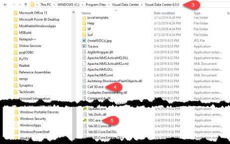
Eaton
www.eaton.com/powerquality
LEGAL NOTICE

Copyright © 2020. Eaton. All rights reserved. The contents of this document constitute valuable
proprietary and confidential property of Eaton Corporation and are provided subject to specific
obligations of confidentiality set forth in one or more binding legal agreements. Any use of this material
is limited strictly to the uses specifically authorized in the applicable license agreement(s) pursuant to
which such material has been furnished. Any use or disclosure of all or any part of this material not
specifically authorized in writing by Eaton Corporation is strictly prohibited.

Contact Eaton Support
For your convenience, Eaton provides support to assist you with questions on installation, operation and
troubleshooting. Please contact us at:

softwareconnectivityts@eaton.com

800-356-5737 option 2, option 5, option 1

                                                    2                                            Contents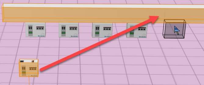
Contents
Contents ........................................................................................................................................................ 3
1. Introduction .............................................................................................................................................. 8
          3D Application Overview ................................................................................................................... 8
          Client versus Web .............................................................................................................................. 9
2. 3D Client Interface .................................................................................................................................. 10
          How to Access the Client Interface.................................................................................................. 10
          Login to the Client Application ........................................................................................................ 10
          Login Profiles ................................................................................................................................... 10
          Login to Incorrect URL Error Message ............................................................................................. 11
          Running the Client in a Citrix Environment ..................................................................................... 11
          Manage Proxy Settings .................................................................................................................... 13
          Login to a Profile .............................................................................................................................. 14
          License Quota Control ..................................................................................................................... 14
3. Home Page .............................................................................................................................................. 15
          Navigation Tree................................................................................................................................ 15
          Data Charts and Dashboards ........................................................................................................... 16
          Ribbon Menu Icons .......................................................................................................................... 17
4. Search for a Device ................................................................................................................................. 19
                 To perform a standard search, follow these steps: ................................................................. 19
                 To perform an advanced search, follow these steps: .............................................................. 19
          Search for a Cable ............................................................................................................................ 20
5. Floor Plans ............................................................................................................................................... 21
          Access Floor Plans ............................................................................................................................ 21
          Floor Plan Basics .............................................................................................................................. 21
                 Mode Menu.............................................................................................................................. 21
                  Save and Pin Icons .................................................................................................................... 21
                 Ribbon Menu and Ribbon Bar .................................................................................................. 21
          Application Tabs and Ribbon Bar..................................................................................................... 23
                 Explore Tab ............................................................................................................................... 24
                 Edit Tab..................................................................................................................................... 25
                 Data Tab ................................................................................................................................... 26

                                                                                3                                                                    Contents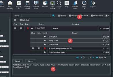
Rack Tab ................................................................................................................................... 26
                 Services Tab .............................................................................................................................. 27
                 Help Tab ................................................................................................................................... 28
           Left Side Tabs .................................................................................................................................. 28
                 Devices Tab............................................................................................................................... 28
                 Model Tab ................................................................................................................................ 29
                 Cables Tab ................................................................................................................................ 30
          Right Side Device Data Tabs ............................................................................................................ 30
                 Layer Tab .................................................................................................................................. 30
                 Graphs Tab ............................................................................................................................... 30
                 Attributes Tab........................................................................................................................... 31
                 Alarms Tab................................................................................................................................ 31
                 File Depot Tab .......................................................................................................................... 31
6. Floor Plan Editing Tasks........................................................................................................................... 32
          Enter Floor Plan Edit Mode.............................................................................................................. 32
          Navigation Shortcut Keys................................................................................................................. 32
          Place Devices on the Floor............................................................................................................... 32
          Place Cable/Fiber Trays on the Floor ............................................................................................... 33
          Tap Box Snap-To Power Bus Bar ...................................................................................................... 33
          Connect Cable Tray Components .................................................................................................... 34
          Move Devices................................................................................................................................... 34
          Move Multiple Devices at the Same Time ....................................................................................... 35
          Delete and Save Devices .................................................................................................................. 35
            Clone Devices................................................................................................................................. 36
7. Rack Builder ............................................................................................................................................ 37
          Rack Builder Components................................................................................................................ 37
          How Devices Are Assigned to a Rack ............................................................................................... 37
                 Assign Devices Already Defined in Device Manager ................................................................ 37
                 Creating New Devices............................................................................................................... 38
          Reposition/Re-State Rack Devices ................................................................................................... 39
                 Manual Moving ........................................................................................................................ 39
                 Re-State Rack Devices .............................................................................................................. 39
                 Cancel Reservation ................................................................................................................... 39

                                                                              4                                                                   Contents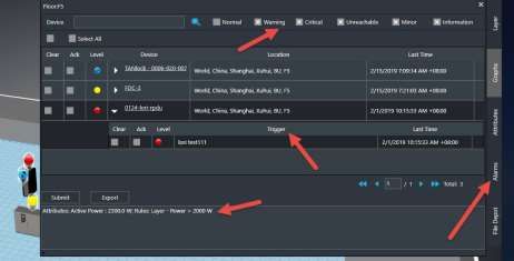
Decommissioning a Device....................................................................................................... 40
                 Planning a Decommission ........................................................................................................ 40
                 Decommission a Planned Decommissioned Asset ................................................................... 40
                 Cancel a Decomissioning .......................................................................................................... 40
          Remove Devices from Racks ............................................................................................................ 41
          Add Non-Rackmount Devices .......................................................................................................... 41
          View a Rack Summary...................................................................................................................... 41
          Move Device Tool ............................................................................................................................ 41
          Place Components into Enclosures ................................................................................................. 42
          Device Collision Management ......................................................................................................... 42
8. Floor Plan Layers ..................................................................................................................................... 43
          Layer Options ................................................................................................................................... 43
                 UI Layers ................................................................................................................................... 43
                 Rack Layers ............................................................................................................................... 43
                 Environment Layers.................................................................................................................. 44
                 Energy Layers ........................................................................................................................... 45
          Layer Filters...................................................................................................................................... 45
                 Filter By Layer ........................................................................................................................... 46
                 Filter By Device ......................................................................................................................... 46
          Layer History .................................................................................................................................... 47
9. Alarm System .......................................................................................................................................... 48
          Alarms Overview.............................................................................................................................. 48
          Active Alarm Panel........................................................................................................................... 48
                 Filter Options ............................................................................................................................ 48
                 Acknowledge Alarms ................................................................................................................ 49
                 Clear Alarms ............................................................................................................................. 49
                 View Detailed Alarm Information ............................................................................................ 50
          View Alarm History .......................................................................................................................... 50
          Export Data to an Excel Spreadsheet .............................................................................................. 50
10. Capacity Planner ................................................................................................................................... 51
            Capacity Information ..................................................................................................................... 51
            Model New Devices ....................................................................................................................... 51
            Plan for the Decommissioning of Devices ..................................................................................... 52

                                                                               5                                                                   Contents
11. Services Module .................................................................................................................................... 53
            Services – Asset Info ...................................................................................................................... 53
            Services – Warranty ....................................................................................................................... 53
            Services - Event Scheduling ........................................................................................................... 54
                   Schedule ................................................................................................................................. 54
                   Calendar ................................................................................................................................. 56
                   Log .......................................................................................................................................... 57
12. Device Central ....................................................................................................................................... 58
            Summary Tab ................................................................................................................................. 58
            Alarms ............................................................................................................................................ 58
                   Acknowledging Alarm Condition ............................................................................................ 58
                   Export Alarms ......................................................................................................................... 59
            Services .......................................................................................................................................... 59
            Warranty ........................................................................................................................................ 59
            Port Mapping ................................................................................................................................. 59
            Root Cause Analysis ....................................................................................................................... 59
                   List View ................................................................................................................................. 60
                   Tree View................................................................................................................................ 60
            Impact Analysis .............................................................................................................................. 60
                   List View ................................................................................................................................. 60
                   Tree View................................................................................................................................ 61
            Associated Devices ........................................................................................................................ 61
                   Creating a Device Association List .......................................................................................... 62
13. Device Action Keys ................................................................................................................................ 63
            Apply the Impact Analysis Filter .................................................................................................... 63
            Apply the Power Path Filter ........................................................................................................... 63
            Apply the Network Path Filter ....................................................................................................... 64
14. Profile Builder ....................................................................................................................................... 65
            Create New Model Profile ............................................................................................................. 65
            Delete a Model Profile ................................................................................................................... 65
15. File Depot .............................................................................................................................................. 66
            Create Folders................................................................................................................................ 66
            Upload Files ................................................................................................................................... 66

                                                                                6                                                                    Contents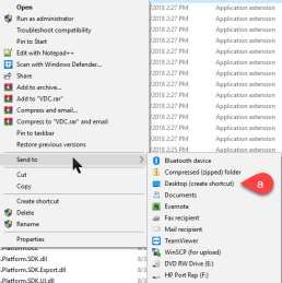
Rename Folders and Files .............................................................................................................. 67
            Delete Folders and Files................................................................................................................. 67
16. Uninstall ................................................................................................................................................ 68

                                                                               7                                                                   Contents
1. Introduction
        3D Application Overview
The 3D Client User Guide provides detailed instructions for implementing and maintaining the
application.

The application portal lets you access a wide array of data information from several disparate sources in
one consolidated interface. The power of this aggregation is the simplicity it provides to operators to
monitor and control both Facilities and IT devices in the data center environment. Since the application
is vendor neutral, any device can be included in the interface and monitoring capabilities.

The application provides the following features for data center operators:

    •   Visual Navigation and Information to multiple floor plans
    •   Navigation to Main Data Center floor plans or Remote IT closets
    •   Real-time data metrics related to any device in the system
    •   Historical trend analysis for metrics defined for devices
    •   Reporting capabilities for user, device, performance and executive reporting requirements.
    •   Service Management scheduling and Warranty Tracking
    •   Integration to third party software solutions. For example, Power Strip controls, IP Camera
        Systems, Card Access Security Systems, Other Vendor Support and Maintenance portals, third
        party Monitoring applications, and more are supported.
    •   Integrated File Depot for document aggregation and management. This feature provides a single
        location for all data center related As Built drawings, Vendor Contract, Support Agreements,
        Photos, Policies and Procedures related to your environment.
    •   Complete Design management of navigation and floor plans. Administrators can assign new
        devices to floor plans and customize the images and menu links associated with them.
    •   Full featured Rack Builder. This feature permits administrators to create online graphical
        representations of their rack layouts. Key information related to devices and racks can then be
        viewed individually or at the rack level to understand the Weight, Power and physical
        characteristics of that rack.
    •   Complete Administrator command of the Access Control Rights of users on the system. Floor
        plans, Devices and Reports are all controlled by standard User and User Group access rights in
        the System Administrator area of the application.

                                                    8                                        Introduction
Client versus Web
The application provides two interfaces for the user to access with each providing some different
functions. In many cases the features overlap, the 3D Client interface is the interface which provides
advanced data analysis and visualization features.

    •   Location Studio – Build and configure the navigation tree for all locations managed by the
        application. Create floor plans for assigning devices. 3D Client links to Web Interface.
    •   Device placement – Assign, remove and relocate devices on floor plans. Available in both 3D
        Client and Web Interface.
    •   Device Data Viewing – View all data related to a device including alarms, graphs, trend charts,
        service events, port mappings, file depot and more. Available in both 3D Client and Web
        Interface.
    •   Alarms – View all alarm information for locations and devices. Available in both 3D Client and
        Web Interface.
    •   Site Summary Data – View summary data related to sites for energy consumption and energy
        costs based on device performance of devices at that location.
    •   Port Mapping – Define network and power relationships between devices. 3D Client links to
        Web Interface.
    •   Project Wizard – Create work order based device actions and assign tasks to users of the
        application. 3D Client links to Web Interface.
    •   Network and Power Paths – Create one-line summary of the network, a power tree of a facility,
        or both. This feature allows logical and physical definitions.
    •   Capacity Planner – Analyze key capacity metrics related to locations and devices. This tool
        allows for what if comparisons of actual and modeled device scenarios.
    •   Root Cause | Impact Analysis – Analyzes the port connections to determine impacts and
        dependencies for devices connected on the power and network paths.
    •   Data Control – Manual change of data values or scheduled calendar changes to be automatically
        changed based on a user defined calendar for changes.
    •   Reports – View all reports related to device performance and application information. 3D Client
        links to Web Interface.
    •   Services – View and manage calendar events and warranty data for all devices in the system.

                                                    9                                        Introduction
2. 3D Client Interface
How to Access the Client Interface
The application client package is installed on the client computer system. The package provides
application files to use for accessing an instance. The following are three ways to access the client
interface from a computer on which the application is installed:
• Start Menu – Lets you run the program from the Start Menu.
• Desktop Icon – Lets you run the 3D client by double-clicking this icon. During the client
installation process, a desktop icon is added to the user’s desktop.
• File Manger – Lets you run the .exe file, which is installed to the following location by default
(the final folder will have a version number of the installation package). Note that installers can
install this package to a different folder during the installation process.
Login to the Client Application
The login process and login issues for the client are the same as those defined for the web interface.
When prompted, you provide a user name and password combination to access the main application
interface. During the logon process, you can choose supported language variants from a drop-down list.
The same issues and messages appear for the logon and the web-based interface.
Login Profiles
The application lets you create multiple access profiles. This feature lets you access multiple instances
from your client by using a single version of the client software. If one or more of the instances are of
different versions, you will need to have a different client for each. All clients will access the same
Settings file so maintenance of separate Settings files is not needed.
When the client installation is complete, you are prompted to create the default access profile. The
profile consists of the URL used to access the interface in the web browser. If new profiles need to be
added to the client, you can create them by accessing the Settings application from the Windows
Program menu.
When this program is opened, you can click the New button to define a new profile for the client. Enter
the URL to be used to access the new instance. The new profile is added to the profile list. Note that
these settings are saved to the following windows file:
c:\users\[your windows logon name]\appdata\local\VDC\VDC.exe.config
If multiple profiles exist on the client, you can select the profile that you want to use to connect when
you open the application. If the client can establish a connection to the selected server instance, the
logon page appears to let you connect to the system.
10 3D Client InterfaceLogin to Incorrect URL Error Message
When user's login with the incorrect URL, an error message window will indicate that the URL is not
correct and the correct URL is provided.
Incorrect URLs include:
• Any URL other than the one designated during installation
• The IP address
• A URL that resolves to the IP address but was not the URL designated during installation
Running the Client in a Citrix Environment
In a Citrix environment the user does not have a personal folder to retain the 3D client settings. This can
be resolved by adding login information to the application string in the desktop shortcut. You will need
the following information:
• URL including the http:// or https://
• Your VCOM username
• The encrypted password for that VCOM username
The steps below will walk you through getting the necessary information and imbedding it in a 3D client
shortcut for future use.
1. Open a notepad document so you can paste the information strings for use in the final step.
2. Add URL to the notepad document including the http:// or https:// with final slash and your
username
http://vdc55-2543.company/
username
3. In a Windows Explorer window, navigate to the Visual Capacity Optimization Manager 6.x folder
11 3D Client Interface4. Locate the Call 3D.exe tool and double click to run
a. Input your password
b. Click the Encrypt button
c. Click Copy button to copy the Encrypted text to the clipboard
d. Paste the Encrypted password text to the notepad file
5. Create a desktop shortcut for the VCOM.exe file.
a. Right click on VCOM.exe and select Send to Desktop (create shortcut). This creates a
shortcut on the desktop named VCOM.exe.
6. In the notepad file construct the information string that will be pasted into the shortcut and
Copy.
The syntax is: -H URL -u USERNAME -p ENCRYPTEDPASSWORD
12 3D Client Interface7. Right Click the VCOM.exe shortcut on your desktop.
a. In the Target field, after the quote at the end of the path add a space and paste the
information string from your notepad file.
b. Click OK to save the change.
8. Double Click the desktop shortcut and the 3D Client should launch and automatically connect to
the URL and login.
Manage Proxy Settings
The application has a built-in SSH Proxy component that lets you connect to the instance from a remote
location (only if connection to the server through SSH is granted). This setup is configured through the
Settings page. The port tunneling service performed through the 3D application remains connected
during the duration of your session.
Note: You can access the 2D session of a server connected through SSH only if the 3D application is
running and a connection is established.
Follow these steps:
1. Add the following line to your C:\Windows\System32\drivers\etc\hosts file:
127.0.0.1 SERVER_URL
Save and Close the hosts file after this edit has been made.
2. Open the Settings application.
For new installations, the settings window is automatically opened by the application when the
installation of the server is completed.
To add a profile or modify an existing profile after the initial installation of the application,
follow these steps:
a. Locate the application folder in the Start menu.
b. Select the Settings application within the directory.
13 3D Client Interfacec. Click New to create a new profile or double click an existing profile to edit its properties.
3. Select the SSH Proxy check box.
4. Specify values in the SSH Proxy input fields.
a. Server IP - Specifies the IP address of the server that you are trying to SSH into.
b. Port - Indicates port 22 unless you specify a different value.
c. Username - The username should be a user with access to the server such as root.
d. Password - Enter the root password.
Note: When the configuration is confirmed and the user runs the 3D Client and
connects to the application server they will use their regular username and password.
Their access to data on the application server will be controlled by the user access rights
configured by the administrator of the application server.
e. Description - Entering a description is optional.
5. Click Submit.
The server tests the proxy settings.
6. Do one of the following:
a. If the connection is accepted, close the settings window.
b. If connection is refused, verify that settings are correct and resubmit the proxy settings.
Note: The session attempt will timeout if an incorrect user and password combination is
supplied for the connection.
Login to a Profile
After creating an SSH Proxy connection in Settings, you can log in to that profile through the Profile
window.
Follow these steps:
1. Open the application.
2. Select the Server Host profile.
3. Click Verify.
a. If all five ports pass, continue to the next step.
b. If one of the five ports fail, go to the Settings window and verify SSH Proxy settings for
the problematic Server Host profile.
4. Click OK to close the verification window.
5. Click OK to activate the selected Server Host profile.
License Quota Control
When logging into the 3D client the application will check the system usage versus the license quotas
purchased by the customer. If there is an excessive number of licenses used then the access to the 3D
client will be blocked. Users will need to access the application in the web interface using an
administrator account to purge excessive quota items or purchase additional licenses to apply to the
server. Once the quota check is in compliance, then standard login functionality is restored.
14 3D Client Interface3. Home Page
The client interface is designed to open separate Windows for each function performed. This feature
lets you take advantage of multiple monitors or easily lay out the various functions on a large network
operations center screen. Each separate window function is defined further in this document, but this
section describes the Home Page layout and key functions.
Navigation Tree
Lists all locations to which the user has View access rights. There are two tabs Navigation and My Sites.
• Navigation Tab - displays the full navigation tree
o You can click the nodes of the tree to view summary data for each part of the location
tree. You can also double-click floor or area names to open the floor view of the
location.
o The numbers under the node name represent the number of devices in that node and
all child nodes that match the five alarm conditions. Red indicates Critical alarms, Yellow
indicates Warning alarms, Blue indicates Unreachable alarms, Purple indicates Minor
alarms and Lite Blue indicates Information. Monitored devices that have not been
assigned a floor location are counted in the Unassigned Devices node (the last node in
the tree).
• My Sites Tab - displays the list of pinned floor plans
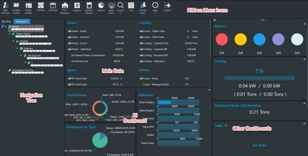
15 Home PageData Charts and Dashboards
• Shows dynamic system information and includes the main data area and several dashboards.
The user's options for the home page layout are remembered for the next login.
• Main Data - is the large area in the center of the screen and the display is controlled by the Main
Data icon in the Ribbon Menu. The options include Site Data, Alarms, Dashboards, Trend Charts,
Abstract Model and Detailed Model. Details for each option are listed below.
• BI Dashboard - is located under the main data area and displays utilization information. It can be
hidden by clicking the X in the upper right corner of the area. To show simply click on the BI
Dashboard button that appears when it is hidden.
• Other Dashboards - The dashboards located on the right side of the screen include Alarms,
Estimated Yearly CO2 Emission, PUE, Cooling and Tasks (current project assignments).
o These dashboards can be re-ordered by dragging and dropping where a green line
appears.
o These dashboards can be hidden by clicking on the X in the upper right corner of the
dashboard. To show a hidden dashboard select it from the pull-down list at the top of
the column.
16 Home PageRibbon Menu Icons
From left to right, these icons provide quick access to common functions from this main screen.
• Web Interface – Opens the web interface home page in a browser window.
• Location Studio – Opens the web interface navigation tree page related to managing and
building out the locations present in the navigation tree.
• Profile Builder – Lets you create custom device templates.
• Services – Lets you define service events, warranty dates, and other advanced asset
management items for devices in the system.
• Calendar – Opens the web interface Calendar page listing all events.
• Port Mapping – Opens the web interface port mapping page.
• Projects – Opens the web interface projects page.
• Capacity Planner – Provides building and location power consumption and power analysis
functions.
• Reports – Opens the web interface data analysis reports page.
• Main Data – Lets you select the data that will be displayed in largest and Main window of the
home page. The options with their descriptions are listed below. The selected option is
remembered and will be displayed when the user logs in.
o Site Data – The Site Data panel includes the Location Power, Cooling, Space information.
This data here is similar to the PUE Summary.
o Alarms – Displays the active alarms for devices in the selected node of the navigation
tree. This list is updated every 30 seconds.
▪ 1. Checkboxes allow user to specify which alarms are visible.
▪ 2. The alarm shows the Trigger which caused the alarm.
▪ 3. Details shows the attribute values and trigger rules which caused the alarm
o Abstract Model/Detailed Model – When a floor node is selected in the navigation tree
these options toggle between abstract and detailed floor views.
17 Home Page• Search icon – Lets you search Devices, Cables and Associated Devices.
o Devices – Lets you search for a device.
o Cables – Opens web interface search page.
o Associated Devices – Lets you view and create device associations.
• Log – Provides access to the system log file. Note that this icon is available only for users that
belong to the administrators.
• Current Users – Lets admin users view current users logged into the application and terminate
sessions as needed.
• Help – Provides information for submitting a Model Request, accesses the User Guide and links
to the Support Portal.
• Logout – Lets you log out and terminate the current session.
18 Home Page4. Search for a Device
You can search for a device within the instance’s device inventory by selecting the Search icon from the
home page ribbon menu and selecting Devices from the drop-down list.
Two different searches can be performed:
• Standard search - Lets you search all devices based on the specified device name.
• Advanced search - Lets you apply various filters to search criteria.
The advanced search gives you more control over the search criteria. You can view previous searches
that have been completed by selecting the time clock icon in the top right corner of the Search window.
You can also save searches and review them at any time.
The advanced search lets you perform multiple searches. To open a new search, you select the plus icon.
The following filters can be applied to the advanced search:
Filter Description
Type This value is from the Device Properties.
Manufacturer This value is from the Device Properties.
Model This value is from the Device Properties.
Device Group This value is from the Device Properties.
Asset Tag This value is from the Device Attribute named Asset Tag.
Serial Number This value is from the Device Attribute named Serial Number.
Software This value is the Device Application from both CMDB and the custom definition.
Create Time This value is from the Device Attribute named Create Date.
Status This value is the Assigned/Unassigned status of the device.
Probe This value is the Active/Inactive status of the monitoring device.
IP Address This value is from the Monitor tab on the device if the device is set to monitor. If the device is set to
static, this value is populated from the IP Address attribute for the device.
To perform a standard search, follow these steps:
1. Type the device name in the Device text box.
2. To apply a wildcard filter use the '%' symbol before the letters.
3. Click the Search icon to apply the filter.
To perform an advanced search, follow these steps:
1. Type the device name in the Device text box.
To apply more filter options to the search select the funnel icon in the top right corner of the
Search window.
2. Click Search to apply the filter.
3. Click Save. The search is saved.
A Search is performed, and qualified devices are listed in a table. The columns, starting from the left side
of the table, are defined as follows:
19 Search for a Device• Device Status – Status of the device (Available, Operational, Planned, Reserved,
Decommissioned)
• Device Central – Device's Device Central
• Select the icon to open that device's Device Central
• Device Information – Device attributes
• Select the icon to open the device information and modify its attributes.
• Name – Device Name
• Type – Device Type
• Model – Device Model
You can export the search results to an Excel file by selecting the Export button located on the bottom of
the Search window.
Search for a Cable
You can search for a Cable within the instance by selecting the Search icon from the home page ribbon
menu and selecting Cable from the drop-down list. This opens the web interface search function where
you can search for cables, attributes and devices.
20 Search for a Device5. Floor Plans
The floor plan view in the client application is where you can access and view the majority of the device
and site data. This section covers all the functions and features related to the floor plan view in the
client application.
Access Floor Plans
To open a floor plan view in the client, go to the navigation tree on the main page of the client
application.
• Double-click the floor name in the navigation tree to open the floor view in a new window
• If Main Data is set to Abstract Model and you see the building displayed, you can Double-click
the floor on the building to open the floor view in a new window
• If you double click an area on the navigation tree, just that area and its devices will be visible in a
new window. From there you can use the Up One Level button to view the whole floor.
Floor Plan Basics
The floor plan window provides many features. They are arranged for easy access to a variety of data
points from this single screen.
Mode Menu
Select by clicking on the drop-down Mode Menu next to the application logo on the upper left. The
menu displays the current mode.
Provides these options:
• View Only Mode – Provides a read-only view option of the current floor plan. By default, any
time a floor is opened, it is in View Only Mode.
• Edit Mode – Lets you assign, move and delete devices on the floor plan. Only users with rights to
Edit Mode can access this menu item and make changes to the location. This right is controlled
at the User Group privilege level.
• Close – Closes the floor plan window.
Save and Pin Icons
• The save icon, saves changes to the floor plan.
• The pin icon saves the current floor plan to My Sites tab in the navigation tree.
Ribbon Menu and Ribbon Bar
Quickly access information related to the view and perform functions on devices. Each menu option is
defined further in this section.
21 Floor PlansLeft Side Device Tabs in Edit Mode
View devices in the application.
• Devices – By default lists all devices in the Current Location. Using radio buttons, you can switch
to All and Available devices when in Edit Mode.
o Search – Search for device name, asset tag, serial number and IP address from devices
in the Current Location by default. When in Edit Mode it will search All or Available
devices based on radio button selected.
o Add Criteria – Adds search fields for Type, Manufacturer, Product Line, Model, IP
Address, Asset Tag, Serial Number and Life Cycle attributes. The system will find the
device where the attribute contains the text entered in the box.
• Model – Select Model radio button to show list of models. Select Model Profile radio button to
show list of defined Model Profiles which have been created using the Model Profile tool. (Not
available in View Only Mode)
o Search and Add Criteria behave as noted above against the list of models in the system.
o Note: Users can drag and drop available devices, models and model profiles to the floor.
When you drag a model or model profile the system will prompt you to name the newly
created device, select Group, Life Cycle and quantity.
• Cables – List the cables for the current location and allows the list to be exported with the
Export button. To view selected Cables go to the Cables Show/Hide icon and toggle on Cables.
Right Side Device Data Tabs
Quickly access information related to the current view.
• Layer – Displays the layer window so that you can open a layer view. Only visible when viewing
the floor level. Works with Add Layer Map from the Layer tools in the ribbon bar.
• Graphs – Opens the selected device's Graphs page in a web browser.
• Attributes – Displays list of monitored datapoints, value, unit and trend charts available for the
selected device.
• Alarms – Displays the alarm panel, which shows the active set of alarms for the current view.
• File Depot – If no device is select on the floor plan the File Depot tab is displayed and shows a
list of files that you can open, based on the currently selected view.
22 Floor PlansMain Window
Displays all devices currently assigned to the floor plan. Alarm indicators show the alarm state of each
device.
Alarm LED - Click the LED on the device and the Alarm panel shows Trigger name instead of Monitor
Attribute. Detail is the attribute value and trigger rules.
Right-Click Device Option
• Right-clicking a device to presents device-specific options. Different options are made available
depending on which device type is selected.
Application Tabs and Ribbon Bar
Application Tabs and Ribbon Bar
The tabs along the top provide maximum functionality on the floor plan page while keeping the key
features organized for ease of use. The following sections cover each of the tabs and their features in
the ribbon bar.
23 Floor PlansExplore Tab
The Explore tab lets you move around the screen, navigate location levels, and show or hide information
on the screen.
• Refresh – Updates the 3D application with the current instance. Refresh is only available when
in View Only mode. To refresh the screen when in Edit mode, select View Only mode.
• Reset – Resets the view of the current floor plan to the default when the view is originally
opened.
• Zoom In/Out – Zooms in and out on the current floor plan.
• Other Camera Control Buttons (arrows) – Let you move, pan, rotate, and tilt the floor plan for
better viewing.
• Go Back/Go Forward – Return to the previous view. For example, if you go from floor plan to a
rack view, the Go Back button returns you to the floor plan view.
• Up One Level – Moves up the navigation tree one level from the current view. The levels are
Device, Rack, Floor, and Building.
• Generate Humidity/Temperature – Displays the thermographic images for associated humidity
and temperature points in the current floor plan view and toggles the display.
• Show/Hide Functions – check boxes to toggle viewing of various elements on the floor are now
grouped under five icons: General, Device Status, Racks, Devices and Cables
o General – Toggles the display of the Floor, Room Name and Walls.
o Device Status – Toggles the display of:
▪ Life Cycle - Displays the lifecycle of devices in the floorplan view. A legend is
displayed which defines the colors of the devices.
▪ Showing LEDs for Critical, Warning, Unreachable, Minor, Information and
Normal Alarms. This control is helpful when you would prefer to see only
Warning, Critical, and Unreachable LEDs on the floor plan.
o Racks – Toggles the display of:
▪ Rack Capacity - Displays LEDs based on rack capacity components: weight, amps,
kW, U space.
▪ Rack Category – Displays the colors assigned to the racks based on the Rack
Category attribute of the rack. Note, the options for Rack Category can be
managed using the Attributes Manager tool in the web interface.
o Devices – Toggles the display of the following device types: Chiller, Fire Suppression,
Power Bus, Furniture and Sensor Flag.
▪ Power Bus - Displays the power bus bar and associated tap boxes if checked.
▪ Sensor Flag - Displays an icon where sensors are placed so users can more easily
see sensor placement on large floorplans.
24 Floor Planso Cables – Toggles the display of:
▪ Cables – Displays cables selected in the right side Cables tab.
▪ Cable Trays – Displays the cable tray that is above or below the racks. If cables
are being displayed, clearing the cable trays check box hides the cables.
▪ Fiber Channel - Displays the fiber channel components.
• Layer Functions
o Add Layer Map – Displays an additional layer map window in the top right corner of the
screen. Multiple layer maps can be opened simultaneously to view different data points
in multiple windows.
o Not Filtered/Filtered – Icon changes indicating if there is a filter applied or not. Tool
allows you filter devices on the floor based on listed filter criteria.
Edit Tab
The Edit tab provides functions for organizing devices on the floor. Most of these functions are available
only when you are in Edit Mode. You must have rights assigned to your User Group to be able to enter
Edit Mode.
• Save – Saves changes made to the floor plan. Note that changes to device locations, and so on
are not committed to the floor plan until the Save button is clicked.
• Remove – Removes the selected device from the floor plan. This action removes the device from
the floor plan. It does not delete the device from the database.
• Undo/Redo – Erases previous action items or regenerates the action items that you created.
• Hot/Cold Containment – Lets you create a see-through container room that can be placed over
racks. Click the icon and then drag the cursor on the floorplan to create the containment device.
Once you have established the container, a pop up lets you define the name and the dimensions
of the container. Once created you will see the container in the device list and you can move it
around. Note, you may right click and select Modify to update the properties of the container
device. If changes are made to the dimensions then you will need to close and reopen the
floorplan to view the updated device dimensions.
• Align functions – Lets you align multiple devices with each other. Select the devices by pressing
the Ctrl key and clicking several devices. This action aligns the chosen side of the devices. The
reference for the alignment is the chosen side of the first device selected. So the movement of
the devices is based on the first device selected.
• Join functions – Lets you join multiple devices side by side. This feature is very helpful for placing
multiple racks in a row on the floor plan. The first device selected in the series of devices is the
reference for joining devices. All devices move and attach to the first device. The second device
selected attaches directly to the first device, the third device attaches to the second device, and
so on. All devices automatically rotate in the join function so that all devices face the same
direction.
25 Floor PlansNote: When the Join function is selected, you can add space between the devices by entering
the distance of space required.
• Rotate functions – Lets you rotate the device based on the option selected. CW refers to
clockwise, and CCW refers to counter-clockwise.
• Move Device functions – Lets you move the device in the direction selected. The device moves
relative to the direction it is facing.
Data Tab
The Data tab provides easy access to the variety of data available in the application.
• General Functions
o Summary – Provides key information related to the currently selected floor plan.
o Properties – Displays the device attributes of the currently selected device.
o Links – Displays the list of links configured for the currently selected device. These links
can be URLs or documents.
o Device Central – Displays everything that is pertinent—name plate data, port mapping,
trend charts, alarms—to a selected device.
• Alarm Panel – Displays the Alarm Panel at the chosen level of navigation. You can view the
alarms for the current device, floor, or building based on their selection.
• Graphs - Opens the selected device's Graphs page in a web browser.
• File Depot – Lets you see a list of files posted to the selected building or floor.
• Ports – Opens the port mapping module, which lets you map network and power relationships
between devices. You must select a device to open the port mapping module.
Rack Tab
The rack tab is enabled only when you view a rack on the screen. The menu provides key functions that
let you build racks easily. It is available only when you select Edit Mode.
• Shelf – Lets you easily add a shelf to the rack. Clicking a spot in the rack highlights that location
in green. Clicking the shelf button inserts a shelf into the rack at the chosen location.
• Blanking Panel - Lets you easily add a blanking panel to the rack. Clicking a spot in the rack
highlights that location in green. Clicking the blanking panel button selects the size of the panel.
A blanking panel is inserted into the rack at the chosen location.
26 Floor Plans• Reserve Space - Lets you reserve a space of the rack for future use. Clicking a spot in the rack
highlights that location in green. Clicking the blanking panel button selects the size of the panel.
An orange reserve space panel is inserted into the rack at the chosen location.
• Patch Panel - Lets you easily add a generic patch panel to the rack. Clicking a spot in the rack
highlights that location in green. Clicking the patch panel button selects the size of the patch
panel. A generic patch panel is inserted into the rack at the chosen location.
• Cable Manager - Lets you easily add a cable manager to the rack. Clicking a spot in the rack
highlights that location in green. Clicking the cable manager button selects the size of the cable
manager. A generic cable manager is inserted into the rack at the chosen location.
• Move Up/Down – Lets you easily move a selected device in the rack up or down 1 or .1 U
positions. Each U position is divided into three, which corresponds to most rack manufacturer
screw hole locations.
• Move to New Rack – Lets you easily move a device from the current rack to a different rack
location.
• Cut/Paste Device – Lets you cut the device form the current rack location and paste it into a
different rack location.
• Remove Device – Removes the selected device from the current rack. Note this action does not
delete the device from the database.
• Rotate Left/Right – Lets you rotate a device left or right to display correctly in the rack. This
option is available only for devices that do not have a U size attribute defined. A good example
of using this option is for a desktop computer sitting on the shelf in a rack.
• Print – Lets you print a PDF of the front and rear image of a selected rack. A list of the devices
within the rack are listed below the images. Multiple racks may be selected using the Ctrl key
and mouse clicks. If Print is selected with multiple racks selected then all racks and devices will
be printed to the PDF document.
• Hide/Show Enclosure – Lets you toggle the view of the rack with or without the enclosure. This
action is helpful for instances when a sensor or other device is mounted to the outside of the
rack.
Services Tab
The Services tab lets you track advanced asset management features for the devices. This tracking
includes service event, product maintenance, warranty tracking, and more. Specific details for the
Services module are covered later in this document. These icons let you view data configured in the
main Services module.
• Asset Info – Lets you track costs, purchase and service dates, and invoice or PO documents with
other advanced asset information.
• Warranty – Lets you view warranty information along with access to the Warranty document.
• Services Calendar – Lets you view a calendar of scheduled events for the selected device.
27 Floor PlansYou can also read