IBM SAN Volume Controller and Storwize Family Native IP Replication
←
→
Page content transcription
If your browser does not render page correctly, please read the page content below

Front cover

IBM SAN Volume Controller
and Storwize Family
Native IP Replication
Implement SVC/Storwize Family native
IP replication

Understand requirements for
configuring native IP replication

Mitigate the effects of IP
latency over distance

 Jon Tate
 Christian Burns
 Derek Rubright
 Lee Sirett

ibm.com/redbooks Redpaper


International Technical Support Organization

IBM SAN Volume Controller and Storwize Family
Native IP Replication

September 2014

 REDP-5103-00
Note: Before using this information and the product it supports, read the information in “Notices” on
 page vii.

First Edition (September 2014)

This edition applies to version 7.2 and above of IBM SAN Volume Controller and Storwize V7000, Storwize
V5000, and Storwize V3700.

© Copyright International Business Machines Corporation 2014. All rights reserved.
Note to U.S. Government Users Restricted Rights -- Use, duplication or disclosure restricted by GSA ADP Schedule
Contract with IBM Corp.
Contents

 Notices . . . . . . . . . . . . . . . . . . . . . . . . . . . . . . . . . . . . . . . . . . . . . . . . . . . . . . . . . . . . . . . . . vii
 Trademarks . . . . . . . . . . . . . . . . . . . . . . . . . . . . . . . . . . . . . . . . . . . . . . . . . . . . . . . . . . . . . viii

 Preface . . . . . . . . . . . . . . . . . . . . . . . . . . . . . . . . . . . . . . . . . . . . . . . . . . . . . . . . . . . . . . . . . ix
 Authors . . . . . . . . . . . . . . . . . . . . . . . . . . . . . . . . . . . . . . . . . . . . . . . . . . . . . . . . . . . . . . . . . . ix
 Now you can become a published author, too! . . . . . . . . . . . . . . . . . . . . . . . . . . . . . . . . . . . .x
 Comments welcome. . . . . . . . . . . . . . . . . . . . . . . . . . . . . . . . . . . . . . . . . . . . . . . . . . . . . . . . xi
 Stay connected to IBM Redbooks . . . . . . . . . . . . . . . . . . . . . . . . . . . . . . . . . . . . . . . . . . . . . xi

 Chapter 1. Introduction to native IP replication in SVC/Storwize . . . . . . . . . . . . . . . . . . 1
 1.1 IP replication overview . . . . . . . . . . . . . . . . . . . . . . . . . . . . . . . . . . . . . . . . . . . . . . . . . . 2
 1.2 Metro Mirror and Global Mirror overview. . . . . . . . . . . . . . . . . . . . . . . . . . . . . . . . . . . . . 2
 1.2.1 Metro Mirror . . . . . . . . . . . . . . . . . . . . . . . . . . . . . . . . . . . . . . . . . . . . . . . . . . . . . . 2
 1.2.2 Global Mirror . . . . . . . . . . . . . . . . . . . . . . . . . . . . . . . . . . . . . . . . . . . . . . . . . . . . . . 3
 1.2.3 Global Mirror with Change Volumes . . . . . . . . . . . . . . . . . . . . . . . . . . . . . . . . . . . . 4
 1.3 Example scenarios . . . . . . . . . . . . . . . . . . . . . . . . . . . . . . . . . . . . . . . . . . . . . . . . . . . . . 4
 1.3.1 Single WAN link to a single input/output group . . . . . . . . . . . . . . . . . . . . . . . . . . . . 5
 1.3.2 Single WAN link to dual I/O groups. . . . . . . . . . . . . . . . . . . . . . . . . . . . . . . . . . . . . 5
 1.3.3 Dual WAN links to a single I/O group . . . . . . . . . . . . . . . . . . . . . . . . . . . . . . . . . . . 6
 1.3.4 Dual WAN links to dual I/O groups . . . . . . . . . . . . . . . . . . . . . . . . . . . . . . . . . . . . . 7
 1.4 SVC/Storwize IP replication in more detail . . . . . . . . . . . . . . . . . . . . . . . . . . . . . . . . . . . 7
 1.4.1 Performance degradation with TCP/IP . . . . . . . . . . . . . . . . . . . . . . . . . . . . . . . . . . 7
 1.4.2 How SVC/Storwize improves performance . . . . . . . . . . . . . . . . . . . . . . . . . . . . . . . 8
 1.4.3 Performance benefit . . . . . . . . . . . . . . . . . . . . . . . . . . . . . . . . . . . . . . . . . . . . . . . 10

 Chapter 2. IP replication configuration overview and considerations. . . . . . . . . . . . . 11
 2.1 IP partnerships . . . . . . . . . . . . . . . . . . . . . . . . . . . . . . . . . . . . . . . . . . . . . . . . . . . . . . . 12
 2.1.1 Intersite link planning . . . . . . . . . . . . . . . . . . . . . . . . . . . . . . . . . . . . . . . . . . . . . . 12
 2.1.2 IP partnership requirements . . . . . . . . . . . . . . . . . . . . . . . . . . . . . . . . . . . . . . . . . 13
 2.1.3 Configuring IP partnerships . . . . . . . . . . . . . . . . . . . . . . . . . . . . . . . . . . . . . . . . . 14
 2.1.4 Remote-copy port groups . . . . . . . . . . . . . . . . . . . . . . . . . . . . . . . . . . . . . . . . . . . 15
 2.1.5 Node port status . . . . . . . . . . . . . . . . . . . . . . . . . . . . . . . . . . . . . . . . . . . . . . . . . . 15
 2.1.6 IP replication link failover . . . . . . . . . . . . . . . . . . . . . . . . . . . . . . . . . . . . . . . . . . . 16
 2.1.7 Using CHAP with IP partnerships . . . . . . . . . . . . . . . . . . . . . . . . . . . . . . . . . . . . . 16
 2.2 Setting up remote copy relationships on SVC/Storwize . . . . . . . . . . . . . . . . . . . . . . . . 17
 2.3 Migrating between FC and IP replication . . . . . . . . . . . . . . . . . . . . . . . . . . . . . . . . . . . 17
 2.3.1 Migration between FC and IP, or IP and FC . . . . . . . . . . . . . . . . . . . . . . . . . . . . . 17
 2.3.2 Migration between IPv4 and IPv6, or IPv6 and IPv4. . . . . . . . . . . . . . . . . . . . . . . 18
 2.3.3 Migration between 1 Gbps and 10 Gbps, or 10 Gbps and 1 Gbps . . . . . . . . . . . . 19

 Chapter 3. Implementing IP replication in the SVC/Storwize family. . . . . . . . . . . . . . . 21
 3.1 Configuring IP replication . . . . . . . . . . . . . . . . . . . . . . . . . . . . . . . . . . . . . . . . . . . . . . . 22
 3.1.1 Overview of required steps . . . . . . . . . . . . . . . . . . . . . . . . . . . . . . . . . . . . . . . . . . 22
 3.1.2 Physical details of an example environment . . . . . . . . . . . . . . . . . . . . . . . . . . . . . 22
 3.1.3 Configure the Ethernet ports on the partner systems . . . . . . . . . . . . . . . . . . . . . . 24
 3.1.4 Create and configure the IP partnership on each of the partner systems. . . . . . . 28
 3.1.5 Creating IP remote-copy consistency groups and relationships . . . . . . . . . . . . . . 32

© Copyright IBM Corp. 2014. All rights reserved. iii
Chapter 4. Best practices and troubleshooting . . . . . . . . . . . . . . . . . . . . . . . . . . . . . . . 45
 4.1 Best practices . . . . . . . . . . . . . . . . . . . . . . . . . . . . . . . . . . . . . . . . . . . . . . . . . . . . . . . . 46
 4.1.1 System configuration . . . . . . . . . . . . . . . . . . . . . . . . . . . . . . . . . . . . . . . . . . . . . . 46
 4.1.2 Performance considerations . . . . . . . . . . . . . . . . . . . . . . . . . . . . . . . . . . . . . . . . . 46
 4.2 Implementation and usage troubleshooting . . . . . . . . . . . . . . . . . . . . . . . . . . . . . . . . . 47
 4.2.1 Error code CMMVC8359E . . . . . . . . . . . . . . . . . . . . . . . . . . . . . . . . . . . . . . . . . . 47
 4.2.2 Error code CMMVC8354E . . . . . . . . . . . . . . . . . . . . . . . . . . . . . . . . . . . . . . . . . . 48
 4.2.3 Error Code CMMVC8353E . . . . . . . . . . . . . . . . . . . . . . . . . . . . . . . . . . . . . . . . . . 49
 4.2.4 Error Code 2020 . . . . . . . . . . . . . . . . . . . . . . . . . . . . . . . . . . . . . . . . . . . . . . . . . . 49
 4.2.5 Error Code 2021 . . . . . . . . . . . . . . . . . . . . . . . . . . . . . . . . . . . . . . . . . . . . . . . . . . 50
 4.2.6 Error Code 2022 . . . . . . . . . . . . . . . . . . . . . . . . . . . . . . . . . . . . . . . . . . . . . . . . . . 51
 4.2.7 Error Code 2023 . . . . . . . . . . . . . . . . . . . . . . . . . . . . . . . . . . . . . . . . . . . . . . . . . . 52

 Appendix A. Command-line interface . . . . . . . . . . . . . . . . . . . . . . . . . . . . . . . . . . . . . . . 53
 Configuring Ethernet ports on the partner systems . . . . . . . . . . . . . . . . . . . . . . . . . . . . . . . 54
 Create and configure the IP partnership on each of the partner systems. . . . . . . . . . . . 55
 Creating IP remote-copy consistency groups and relationships . . . . . . . . . . . . . . . . . . . 55
 Starting the IP remote-copy consistency group . . . . . . . . . . . . . . . . . . . . . . . . . . . . . . . 56

 Appendix B. CHAP Information and Implementation . . . . . . . . . . . . . . . . . . . . . . . . . . 57
 General information on CHAP . . . . . . . . . . . . . . . . . . . . . . . . . . . . . . . . . . . . . . . . . . . . . . . 58
 Configuring CHAP for IP replication . . . . . . . . . . . . . . . . . . . . . . . . . . . . . . . . . . . . . . . . . . . 58
 Configure system-wide CHAP secret . . . . . . . . . . . . . . . . . . . . . . . . . . . . . . . . . . . . . . . 58
 Configure partnership to use the CHAP secret . . . . . . . . . . . . . . . . . . . . . . . . . . . . . . . . 59

 Related publications . . . . . . . . . . . . . . . . . . . . . . . . . . . . . . . . . . . . . . . . . . . . . . . . . . . . . 61
 IBM Redbooks . . . . . . . . . . . . . . . . . . . . . . . . . . . . . . . . . . . . . . . . . . . . . . . . . . . . . . . . . . . 61
 Other publications . . . . . . . . . . . . . . . . . . . . . . . . . . . . . . . . . . . . . . . . . . . . . . . . . . . . . . . . 61
 Online resources . . . . . . . . . . . . . . . . . . . . . . . . . . . . . . . . . . . . . . . . . . . . . . . . . . . . . . . . . 61
 How to get IBM Redbooks . . . . . . . . . . . . . . . . . . . . . . . . . . . . . . . . . . . . . . . . . . . . . . . . . . 61
 Help from IBM . . . . . . . . . . . . . . . . . . . . . . . . . . . . . . . . . . . . . . . . . . . . . . . . . . . . . . . . . . . 61

iv IBM SAN Volume Controller and Storwize Family Native IP Replication
Notices

This information was developed for products and services offered in the U.S.A.

IBM may not offer the products, services, or features discussed in this document in other countries. Consult
your local IBM representative for information on the products and services currently available in your area. Any
reference to an IBM product, program, or service is not intended to state or imply that only that IBM product,
program, or service may be used. Any functionally equivalent product, program, or service that does not
infringe any IBM intellectual property right may be used instead. However, it is the user's responsibility to
evaluate and verify the operation of any non-IBM product, program, or service.

IBM may have patents or pending patent applications covering subject matter described in this document. The
furnishing of this document does not grant you any license to these patents. You can send license inquiries, in
writing, to:
IBM Director of Licensing, IBM Corporation, North Castle Drive, Armonk, NY 10504-1785 U.S.A.

The following paragraph does not apply to the United Kingdom or any other country where such
provisions are inconsistent with local law: INTERNATIONAL BUSINESS MACHINES CORPORATION
PROVIDES THIS PUBLICATION “AS IS” WITHOUT WARRANTY OF ANY KIND, EITHER EXPRESS OR
IMPLIED, INCLUDING, BUT NOT LIMITED TO, THE IMPLIED WARRANTIES OF NON-INFRINGEMENT,
MERCHANTABILITY OR FITNESS FOR A PARTICULAR PURPOSE. Some states do not allow disclaimer of
express or implied warranties in certain transactions, therefore, this statement may not apply to you.

This information could include technical inaccuracies or typographical errors. Changes are periodically made
to the information herein; these changes will be incorporated in new editions of the publication. IBM may make
improvements and/or changes in the product(s) and/or the program(s) described in this publication at any time
without notice.

Any references in this information to non-IBM websites are provided for convenience only and do not in any
manner serve as an endorsement of those websites. The materials at those websites are not part of the
materials for this IBM product and use of those websites is at your own risk.

IBM may use or distribute any of the information you supply in any way it believes appropriate without incurring
any obligation to you.

Any performance data contained herein was determined in a controlled environment. Therefore, the results
obtained in other operating environments may vary significantly. Some measurements may have been made
on development-level systems and there is no guarantee that these measurements will be the same on
generally available systems. Furthermore, some measurements may have been estimated through
extrapolation. Actual results may vary. Users of this document should verify the applicable data for their
specific environment.

Information concerning non-IBM products was obtained from the suppliers of those products, their published
announcements or other publicly available sources. IBM has not tested those products and cannot confirm the
accuracy of performance, compatibility or any other claims related to non-IBM products. Questions on the
capabilities of non-IBM products should be addressed to the suppliers of those products.

This information contains examples of data and reports used in daily business operations. To illustrate them
as completely as possible, the examples include the names of individuals, companies, brands, and products.
All of these names are fictitious and any similarity to the names and addresses used by an actual business
enterprise is entirely coincidental.

COPYRIGHT LICENSE:

This information contains sample application programs in source language, which illustrate programming
techniques on various operating platforms. You may copy, modify, and distribute these sample programs in
any form without payment to IBM, for the purposes of developing, using, marketing or distributing application
programs conforming to the application programming interface for the operating platform for which the sample
programs are written. These examples have not been thoroughly tested under all conditions. IBM, therefore,
cannot guarantee or imply reliability, serviceability, or function of these programs.

© Copyright IBM Corp. 2014. All rights reserved. vii
Trademarks
IBM, the IBM logo, and ibm.com are trademarks or registered trademarks of International Business Machines
Corporation in the United States, other countries, or both. These and other IBM trademarked terms are
marked on their first occurrence in this information with the appropriate symbol (® or ™), indicating US
registered or common law trademarks owned by IBM at the time this information was published. Such
trademarks may also be registered or common law trademarks in other countries. A current list of IBM
trademarks is available on the Web at http://www.ibm.com/legal/copytrade.shtml

The following terms are trademarks of the International Business Machines Corporation in the United States,
other countries, or both:
 DB2® Power Systems™ Storwize®
 FlashCopy® Real-time Compression™ System Storage®
 FlashSystem™ Redbooks® XIV®
 IBM® Redpaper™
 IBM FlashSystem™ Redbooks (logo) ®

The following terms are trademarks of other companies:

Other company, product, or service names may be trademarks or service marks of others.

viii IBM SAN Volume Controller and Storwize Family Native IP Replication
Preface

 IBM® has announced native Internet Protocol (IP) replication using Bridgeworks SANSlide
 technology with its IBM System Storage® SAN Volume Controller (SVC), IBM Storwize®
 V7000, IBM Storwize V5000 and Storwize V3700 virtualized storage systems.

 This combination of SANSlide and the SVC/Storwize family provides a powerful solution for
 clients who require efficient, IP-based replication over long distances.

 This certification gives SVC/Storwize clients a fully supported, transparent technology that
 includes unmatched levels of performance and reliability. With the SANSlide protocol
 acceleration technology, it is now possible to replicate data across continents in a
 cost-efficient way, with little or no loss in performance. At the same time, bandwidth usage
 can improve to over 95%, rather than the 1% - 5% normally achieved in long-distance IP
 networks.

 This IBM Redpaper™ publication shows the steps required to implement this solution
 efficiently and speedily.

Authors
 This paper was produced by a team of specialists from around the world working at the
 International Technical Support Organization (ITSO), Hursley Lab, UK.

 Jon Tate is a Project Manager for IBM System Storage SAN
 Solutions at the ITSO, San Jose Center. Before joining the
 ITSO in 1999, he worked in the IBM Technical Support Center,
 providing Level 2 support for IBM storage products. Jon has 28
 years of experience in storage software and management,
 services, and support, and is both an IBM Certified IT
 Specialist and an IBM SAN Certified Specialist. He is also the
 UK Chairman of the Storage Networking Industry Association.

 Christian Burns is an IBM Storage Solution Architect based in
 New Jersey. As a member of the Storage Solutions
 Engineering team in Littleton, MA, he works with clients,
 IBM Business Partners, and IBMers worldwide, designing and
 implementing storage solutions that include various IBM
 products and technologies. Christian’s areas of expertise
 include IBM Real-time Compression™, SVC, IBM XIV®, and
 IBM FlashSystem™. Before joining IBM, Christian was the
 Director of Sales Engineering at IBM Storwize, before it
 became IBM Storwize. He brings over a decade of industry
 experience in the areas of sales engineering, solution design,
 and software development. Christian holds a BA degree in
 Physics and Computer Science from Rutgers College.

© Copyright IBM Corp. 2014. All rights reserved. ix
Derek Rubright is a Staff Software Engineer, specializing in
 IBM SAN Volume Controller and Storwize V7000, at Research
 Triangle Park in Raleigh, NC. He has over 15 years of
 experience in technical customer support, and 5 years of
 experience in storage and storage area network (SAN)
 environments.

 Lee Sirett is a Storage Technical Advisor for the European
 Storage Competency Centre (ESCC) in Mainz, Germany.
 Before joining the ESCC, he worked in IBM Technical Support
 Services for 10 years providing support on a range of IBM
 Products, including IBM Power Systems™. Lee has 24 years of
 experience in the IT Industry. He is IBM Storage Certified, and
 both an IBM Certified XIV Administrator and Certified XIV
 Specialist.

 Thanks to the following people for their contributions to this project:

 Bill Passingham
 Andrew Martin
 Andrea Sipka
 Matt Smith
 IBM Hursley

Now you can become a published author, too!
 Here’s an opportunity to spotlight your skills, grow your career, and become a published
 author—all at the same time! Join an ITSO residency project and help write a book in your
 area of expertise, while honing your experience using leading-edge technologies.

 Your efforts will help to increase product acceptance and customer satisfaction, as you
 expand your network of technical contacts and relationships. Residencies run from two to six
 weeks in length, and you can participate either in person or as a remote resident working
 from your home base.

 Obtain more information about the residency program, browse the residency index, and apply
 online:
 ibm.com/redbooks/residencies.html

x IBM SAN Volume Controller and Storwize Family Native IP Replication
Comments welcome
 Your comments are important to us!

 We want our papers to be as helpful as possible. Send us your comments about this paper or
 other IBM Redbooks® publications in one of the following ways:
 Use the online Contact us review Redbooks form:
 ibm.com/redbooks
 Send your comments in an email:
 redbooks@us.ibm.com
 Mail your comments:
 IBM Corporation, International Technical Support Organization
 Dept. HYTD Mail Station P099
 2455 South Road
 Poughkeepsie, NY 12601-5400

Stay connected to IBM Redbooks
 Find us on Facebook:
 http://www.facebook.com/IBMRedbooks
 Follow us on Twitter:
 http://twitter.com/ibmredbooks
 Look for us on LinkedIn:
 http://www.linkedin.com/groups?home=&gid=2130806
 Explore new Redbooks publications, residencies, and workshops with the IBM Redbooks
 weekly newsletter:
 https://www.redbooks.ibm.com/Redbooks.nsf/subscribe?OpenForm
 Stay current on recent Redbooks publications with RSS Feeds:
 http://www.redbooks.ibm.com/rss.html

 Preface xi
xii IBM SAN Volume Controller and Storwize Family Native IP Replication
1

 Chapter 1. Introduction to native IP
 replication in SVC/Storwize
 This chapter describes the new functionality introduced with code version 7.2, which supports
 native IP replication across the IBM Storwize family, including IBM System Storage SAN
 Volume Controller (SVC). The functionality of the new feature is covered, along with a
 summary of the SVC/Storwize remote mirror technologies.

 Important: Although this paper provides information about the Storwize V7000 and SVC, it
 also applies to the Storwize V5000 and the Storwize V3700.

© Copyright IBM Corp. 2014. All rights reserved. 1
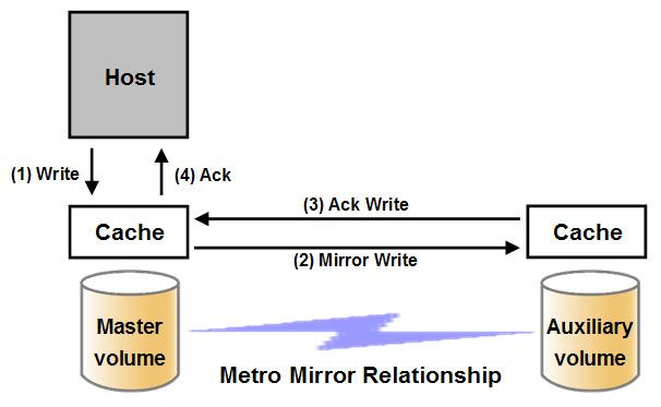
1.1 IP replication overview
 The native Internet Protocol (IP) replication feature enables replication between any
 SVC/Storwize family member running code version 7.2 or higher, using the built-in networking
 ports of the cluster nodes. Following a recent partnership with IBM, it uses SANslide
 technology developed by Bridgeworks Limited of Christchurch, UK. They specialize in
 products that can bridge storage protocols and accelerate data transfer over long distances.

 Adding this technology at each end of a wide area network (WAN) Transmission Control
 Protocol/Internet Protocol (TCP/IP) link significantly improves the usage of the link. It does
 this by applying patented Artificial Intelligence (AI) to hide latency normally associated with
 WANs. Therefore, doing so can greatly improve the performance of mirroring services, in
 particular Global Mirror with Change Volumes (GM/CV) over long distances.

 More details are provided in 1.4, “SVC/Storwize IP replication in more detail” on page 7.

 Tip: Although all versions of 7.2 code offer native IP replication, versions 7.2.0.4 and later
 offer performance enhancements to the SANslide technology.

1.2 Metro Mirror and Global Mirror overview
 Metro Mirror (MM) and Global Mirror (GM) are technologies that enable you to keep a real
 time, or near real-time, copy of a disk at a remote site that contains another SVC cluster or
 Storwize V7000 system.

1.2.1 Metro Mirror
 MM makes synchronous copies, which means that the original writes are not considered
 complete until the write to the destination disk has been confirmed. The distance between two
 sites is usually determined by how much latency the applications can handle. Therefore, MM
 is typically used within metropolitan distances in conjunction with a zero recovery point
 objective (RPO), that is, zero data loss.

2 IBM SAN Volume Controller and Storwize Family Native IP Replication
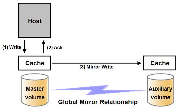
Figure 1-1 shows the order of MM write operations.

 Figure 1-1 Metro Mirror write sequence

1.2.2 Global Mirror
 GM makes asynchronous copies of your disk. This means that the write is considered
 complete after it is complete at the local disk; it does not wait for the write to be confirmed at
 the remote cluster like MM does. This greatly reduces the latency experienced by applications
 if the other cluster is far away. However, it also means that, during a failure, the data on the
 remote copy might not have the most recent changes committed to the local disk.

 Figure 1-2 shows the order of GM write operations.

 Figure 1-2 Global Mirror write sequence

 Chapter 1. Introduction to native IP replication in SVC/Storwize 3
1.2.3 Global Mirror with Change Volumes
 This function (also known as Cycle-Mode Global Mirror), was introduced in Storwize V7000
 V6.3, and can best be described as Continuous Remote IBM FlashCopy®. If you use this
 feature, the Storwize V7000 will essentially take periodic flash copies of a disk, and write
 them to your remote destination.

 This feature completely isolates the local copy from WAN issues, such as line glitches, and
 from sudden spikes in workload that might occur. Bear in mind that your remote copy might
 lag behind the original, depending on how you have set up the cycle time.

 Figure 1-3 shows a high-level conceptual view of GM/CV. GM/CV uses FlashCopy to maintain
 image consistency, and to isolate host volumes from the replication process.

 Figure 1-3 Global Mirror with Change Volumes

 Information: For more information about SVC and Storwize V7000 replication, see IBM
 System Storage SAN Volume Controller and Storwize V7000 Replication Family Services,
 SG24-7574.

 For more information about the SVC, see Implementing the IBM System Storage SAN
 Volume Controller V7.2, SG24-7933.

 For more information about the Storwize V7000, see Implementing the IBM Storwize
 V7000 V7.2, SG24-7938.

 For more information about the Storwize V5000, see Implementing the IBM Storwize
 V5000, SG24-8162

 For more information about the Storwize V3700, see Implementing the IBM Storwize
 V3700, SG24-8107

1.3 Example scenarios
 A SVC/Storwize cluster in one location can be connected to another SVC/Storwize cluster at
 a remote location using various designs. The following sections show example connectivity
 designs.

4 IBM SAN Volume Controller and Storwize Family Native IP Replication
1.3.1 Single WAN link to a single input/output group
 Figure 1-4 shows a single WAN link connecting two Storwize V7000 clusters consisting of a
 single input/output (I/O) group each. In this design, there is a redundant connection from each
 Storwize V7000. Either Ethernet port 1 or 2 can be configured for IP replication, but not both.
 This protects against a node connection failure or a node canister outage (for example, for a
 code upgrade). However, it does not protect against a WAN connection failure.

 Figure 1-4 Single WAN link to a single I/O group

 In this scenario, the remote-copy port group on each system includes two IP addresses, one
 from each node. When the system initially configures, one of these IP addresses is chosen
 from each side. This pairing cannot be chosen or changed by an administrator. In the
 previous example, H1 and M2 have established a connection. If M2 fails, the session will be
 lost but the connection will automatically be re-established between either H1 or H2 and M1.

 The IP addresses do not fail over between nodes for the purposes of IP replication. Although
 the address does in fact move to the other node, as can be seen from the output of the
 lsportip command when a node does fail, this is for Internet Small Computer System
 Interface (iSCSI) purposes only. The IP replication link will be re-established with the
 previously assigned original IP address of the port.

1.3.2 Single WAN link to dual I/O groups
 Figure 1-5 on page 6 shows a single WAN link connecting two Storwize V7000 clusters
 consisting of dual I/O groups. This design also provides redundancy against a node failure,
 but not against a WAN failure. The remote-copy port group on each system has four IP
 addresses, one from each node.

 When the system initially configures, one of these IP addresses is chosen from each side.
 This pairing cannot be chosen or changed by an administrator. If one of the paired nodes
 fails, for example H1, then the connection will be lost as before, but re-established between
 either H2, H3, or H4 and M1, M2, M3, or M4.

 Restriction: Storwize V7000 and SVC nodes with more than two I/O groups are
 supported. However, there is a limitation that only four IP addresses, from two I/O groups
 per system, can be included in a remote-copy port group. If there is only one intersite link
 there must be only one port group.

 Chapter 1. Introduction to native IP replication in SVC/Storwize 5
Figure 1-5 shows a single WAN link connecting two Storwize V7000 clusters.

 Figure 1-5 Dual I/O group with a single WAN link

1.3.3 Dual WAN links to a single I/O group
 The design shown in Figure 1-6 shows a dual redundant WAN link connecting two Storwize
 V7000 clusters consisting of a single I/O group each. In this design, port group 1 and 2 have
 two IP addresses, each on a different node in a different system. This design enables two
 simultaneous IP replication sessions; however, there is only one active port per node. If any
 node should fail, the associated connection would also fail with the loss of half the bandwidth.

 Figure 1-6 Dual WAN links to a single I/O group

6 IBM SAN Volume Controller and Storwize Family Native IP Replication
1.3.4 Dual WAN links to dual I/O groups
 If the required bandwidth means that there must be dual links, then a failure of one might lead
 to an effect on MM or GM if there is no redundancy at the node canister level. In this case, the
 advice would be to have two I/O groups at each site to enable recovery from any single node
 failure or outage, as shown in Figure 1-7.

 Figure 1-7 Dual WAN links to dual I/O groups

1.4 SVC/Storwize IP replication in more detail
 The introduction of native IP replication provides an alternative to the traditional use of a pair
 of Fibre Channel over IP (FCIP) routers, or wave division multiplexors (WDMs) for WAN
 connectivity and to native Fibre Channel (FC) connectivity. Before the release of the version
 7.2 code, if there was a need for replication, the only option was FC connectivity.

 FC technology uses the concept of buffer-to-buffer (B2B) credits as a flow control method to
 maximize the performance of an individual link. The B2B credits are calculated depending on
 the speed and the distance of the link, and represent the number of frames a port can store.
 The faster the link, the more frames can be in flight, and the higher the B2B credit. Traditional
 IP does not have this concept.

1.4.1 Performance degradation with TCP/IP
 Put simply, with TCP/IP, information transfer slows the farther you go. This is because of the
 latency caused by waiting for acknowledgment of each set of packets sent, because the next
 packet set cannot be sent until the previous one has been acknowledged:
 Latency = Round Trip Time (RTT) for a single packet set

 Chapter 1. Introduction to native IP replication in SVC/Storwize 7
Figure 1-8 illustrates this packet flow for a typical IP link.

 Figure 1-8 Link usage on a standard IP link

 Figure 1-9 shows how throughput drops off as latency increases.

 Figure 1-9 Effect of latency on performance

1.4.2 How SVC/Storwize improves performance
 The technology built into the SVC/Storwize code uses TCP/IP latency to its advantage.
 Rather than wait for the acknowledgment to come back, it sends more sets of packets across
 other virtual connections. The number of virtual connections is controlled by the AI engine.
 This improves WAN connection use, which results in a data transfer rate approaching full line
 speed.

 If packets are lost from any virtual connection, the data will be retransmitted, and the remote
 unit will wait for it. Presuming that this is not a frequent problem, overall performance is only
 marginally affected because of the delay of an extra round trip for the data that is resent.

8 IBM SAN Volume Controller and Storwize Family Native IP Replication
Figure 1-10 illustrates data flow with multiple virtual connections.

Figure 1-10 Link usage on an SVC/Storwize IP link

The AI monitors the link performance during data transfer, in addition to the memory and
processor use of the node. It can adjust the number of virtual connections, the receive
window size, and the packet size as appropriate to maintain optimum performance. This
information is retained in the node so that, if the link is stopped and started again, it will
restart with the previously learned settings.

What it does not do
SVC/Storwize IP replication does not manipulate the data in any way. It does not perform any
of the following actions:
 Compress data
 Use deduplication
 Use User Datagram Protocol (UDP)
 Modify TCP/IP
 Use hard disk drive (HDD) caching

What it does do
It improves performance in several ways:
 Uses patented AI
 Fills the pipe
 Operates beneath the operating system
 Uses standard TCP/IP
 Is not affected by compressed and encrypted files

In summary, the SVC/Storwize solution is designed around the principle of using all of the
pipe rather than changing the data. It works best with larger, more consistent amounts of data
rather than bursty type data, which is another reason why we advocate GM/CV for IP
replication. However, it also works with MM and GM.

 Chapter 1. Introduction to native IP replication in SVC/Storwize 9
1.4.3 Performance benefit
 Figure 1-11 shows how the SVC/Storwize solution maintains near line-speed performance by
 masking the latency of the line. Even as the line latency increases, the performance of the
 technology enables the line to continue to exceed that of a plain link.

 Figure 1-11 Storwize V7000 transfer rate comparison

10 IBM SAN Volume Controller and Storwize Family Native IP Replication
2

 Chapter 2. IP replication configuration
 overview and considerations
 This chapter describes the basic concepts and related steps for configuring Internet Protocol
 (IP) replication in IBM System Storage SAN Volume Controller (SVC) and IBM Storwize
 Family products. It is possible to set up IP replication between any IBM SVC/Storwize family
 member running code version 7.2 or later. It also documents the requirements to configure an
 IP partnership and intersite links.

© Copyright IBM Corp. 2014. All rights reserved. 11
2.1 IP partnerships
 This topic provides information about items that relate to IP partnerships.

2.1.1 Intersite link planning
 There are specific intersite link requirements that must be met when planning to use IP
 replication for remote copy.

 If you use IP replication, you must meet the following requirements:
 Transmission Control Protocol (TCP) ports 3260 and 3265 are used by systems for IP
 partnership communications; therefore, these ports will need to be open. Port 3260 is
 used for link initialization and system discovery, and port 3265 is used for the IP replication
 traffic.
 The maximum supported Round Trip Time (RTT) between systems is 80 milliseconds (ms)
 for a 1 gigabits per second (Gbps) link.
 The maximum supported RTT between systems is 10 ms for a 10 Gbps link.
 For IP partnerships, the advised method of copying is Global Mirror with Change Volumes
 (GM/CV). This method is advised because of the performance benefits when used in
 combination with the SVC/Storwize IP replication technology (which works best with
 streaming data rather than bursty data). It is also advised because of the fact that it
 removes the local copy entirely from wide area network (WAN) glitches, and because it
 also smooths input/output (I/O) peaks and enables more efficient use of the intersite link.
 The amount of intersite heartbeat traffic is one megabit per second (Mbps) per link.
 The minimum bandwidth requirement for the intersite link is 10 Mbps. This, however,
 scales up with the amount of host I/O that you choose to do, as shown in Figure 2-1.

 Figure 2-1 Intersite bandwidth requirements

 The following equation describes the approximate minimum bandwidth required between two
 systems with less than ( required background copy in Mbps +
 maximum host I/O in Mbps + 0.125 Mbps heartbeat traffic

 If the link is dedicated and using only GM/CV traffic, then there will be no host I/O. It will all be
 sync I/O, and the link bandwidth formula changes.

 Increasing latency and errors results in a higher requirement for minimum bandwidth.
 Network address translation (NAT) is not supported.

 Important: It is important that both ports 3260 and 3265 are opened up through any
 firewalls for IP replication to be configured successfully. Additionally, ensure that there is no
 NAT in the intersite link.

12 IBM SAN Volume Controller and Storwize Family Native IP Replication
2.1.2 IP partnership requirements
 There are several requirements that must be remembered when creating IP partnerships:
 You can only create IP partnerships between two systems.
 A system can only be part of one IP partnership.
 You can create IP partnerships between any two SVC/Storwize products on the same
 layer. In other words, both systems must be at the storage layer or both systems must be
 at the replication layer. By default, all SVC systems are configured at the replication layer,
 and this cannot be changed. All Storwize systems by default are configured at the storage
 layer, but this can be changed.
 There are many other IBM Redbooks publications on the Storwize family that explain the
 concept of layers in more detail, for example, Implementing the IBM Storwize V7000 V7.2,
 SG24-7938 and IBM System Storage SAN Volume Controller and Storwize V7000
 Replication Family Services, SG24-7574.
 You cannot use link-local addressing.
 If you use IPv4 addressing, the management IP addresses on both systems must be
 IPv4-compliant, and these addresses must have connectivity with each other.
 If you use IPv6 addressing, the management IP addresses on both systems must be
 IPv6-compliant, and these addresses must have connectivity with each other.
 If your system has IPv4 and IPv6 addressing on the ports, you must configure all remote
 copy links between the local and remote site for one of those types of addresses.
 You can configure ports from a maximum of two I/O groups from each system for an IP
 partnership.
 A node can have only one port configured in an IP partnership, either port 1 or 2, but not
 both. Where the optional 10 Gb Ethernet (GbE) card is installed in a system, ports 3 and 4
 are also available.
 If your system has 10 Gbps and 1 Gbps Ethernet ports, you must configure all remote
 copy links between the local and remote site for just one of those speeds.
 Both ends of a partnership must be the same speed.
 A system can have simultaneous partnerships using Fibre Channel over IP (FCIP), but
 with separate systems.
 The IP partner systems must not be visible to each other over FC or Fibre Channel over
 Ethernet (FCoE) connections. FC/FCoE ports of one system should not be listed on the
 other when viewing the output of the lsfsabric command.
 Clusters configured in active IP partnerships should not be zoned with each other for
 FC/FCoE.
 Internet Small Computer System Interface (iSCSI) hosts can access volumes over IP
 ports participating in an IP partnership, but for the best performance it is advised to use
 separate ports for each.
 Virtual local area network (VLAN) tagging of the IP addresses configured for remote copy
 is supported starting with code level 7.4.0.x.
 If you configure two intersite links, you must configure separate remote-copy port groups,
 one for each link.
 If you have one intersite link, you can configure only one remote-copy port group for that
 link.
 No more than two intersite links and two remote-copy port groups are supported.

 Chapter 2. IP replication configuration overview and considerations 13
 If you have one remote-copy port group, configure one port from each node in one I/O
 group in that remote-copy port group.
 For systems with more than one I/O group, ports from a second I/O group can be added to
 the same remote-copy port group.
 If you have two remote-copy port groups and just a single I/O group, then on each system,
 configure one port from one node in the first remote-copy port group, and then a port from
 the other node in the second remote-copy port group.
 For systems with more than one I/O group, ports from a second I/O group can be added to
 each of the two remote-copy port groups.
 For more details about I/O groups, port groups, and node port configurations, see 1.3,
 “Example scenarios” on page 4.
 If you connect systems by directly attaching them without switches, you must have only
 two direct-attach links, and both direct-attach links must be on the same I/O group. You
 should use two port groups, where a port group should only contain the two ports that are
 directly linked.

2.1.3 Configuring IP partnerships
 The procedure to configure a partnership with a remote system using IP replication is
 specified here.

 To configure a partnership with a remote system by using IP replication, follow these steps:
 1. Determine whether you have met all partnership requirements, as described in 2.1.2, “IP
 partnership requirements” on page 13.
 2. For each node port that is to be used in the IP partnership, configure the ports on both
 systems using the command-line interface (CLI) cfgportip command. Configuration
 includes assigning each port to a remote-copy port group, as described in section 2.1.4,
 “Remote-copy port groups” on page 15. Remote-copy port groups are unique to IP
 partnerships, and are the local and remote IP addresses accessible to each other through
 an IP partnership.
 You can also use the management graphical user interface (GUI) to do this task:
 a. Select Settings → Network → Ethernet Ports.
 b. Right-click the port, and then select Modify.
 3. Configure IP replication on the local system by running the mkippartnership command on
 that system. Specify the Challenge Handshake Authentication Protocol (CHAP) secret, if
 necessary. See section 2.1.7, “Using CHAP with IP partnerships” on page 16 for more
 information about CHAP. The partnership link bandwidth parameter must be less than or
 equal to (
For a detailed step-by-step guide to configuring IP partnerships, see Chapter 3,
 “Implementing IP replication in the SVC/Storwize family” on page 21.

2.1.4 Remote-copy port groups
 Remote-copy port groups are unique to IP partnerships. They are the local and remote IP
 addresses accessible to each other through an IP partnership. A remote-copy port group
 must contain at least one IP address in the local system and one IP address in the remote
 system. You must configure individual ports on the local and remote systems and assign to
 them a remote-copy port group number before establishing the IP partnership.

 A remote-copy port group is designated by a number 0 - 2 that identifies a set of IP
 addresses. These port groups are defined as follows:
 Group 0 These ports are not configured for remote copy (supports iSCSI host
 attachment by default).
 Group 1 Ports that belong to remote-copy port group 1.
 Group 2 Ports that belong to remote-copy port group 2.

 The system will select one pair of IP addresses within port groups 1 and 2, one address on
 each system, and will open a remote copy connection between them. It is not possible to
 choose which IP addresses will be selected, it is a system choice based on the IP address of
 the port.

 See 3.1.3, “Configure the Ethernet ports on the partner systems” on page 24 for a
 walk-through describing how to assign IP addresses to ports, and how to assign those ports
 to port groups.

 Tip: Each IP address can be shared for iSCSI host attachment and remote copy
 functionality. Therefore, the appropriate settings must be applied to each IP address. For
 optimal performance, consider isolating iSCSI and IP replication traffic on separate ports.

2.1.5 Node port status
 After an IP partnership has been defined, it is possible to determine which ports are in use in
 a port group and which are not. Using the lsportip command will show the status of all
 ports. In the output, the value of the remote_copy_status field for IPv4 ports, or the
 remote_copy_status6 field for IPv6 ports, will be used. This is true only if the port has been
 configured for use in the IP partnership, and has been selected by the system for sending and
 receiving remote copy data.

 If a port has been configured for use in the IP partnership, but is not currently selected for
 sending and receiving remote copy data, the value of the corresponding field will be unused. If
 a port has not been configured for use by the IP partnership, this field will be blank.

 Example 2-1 on page 16 shows the output from one of the SVCs used for this paper. There is
 one I/O group, and two ports (port 2 on each node) are configured for use in IP replication.

 There are no unused ports in this example, so there are two intersite links in use, and
 therefore two port groups. All other ports are not part of any I/O group, because they
 are blank.

 Chapter 2. IP replication configuration overview and considerations 15
Example 2-1 shows the lsportip command output.

 Example 2-1 The lsportip command output
 IBM_2145:ITSO_Local_Cluster:superuser>lsportip
 id node_id node_name IP_address mask gateway IP_address_6 prefix_6 gateway_6 MAC duplex
 state speed failover link_state host remote_copy host_6 remote_copy_6 remote_copy_status remote_copy_status_6
 1 1 node1 e4:1f:13:30:19:e4 Full
 unconfigured 1Gb/s no active 0 0
 1 1 node1 e4:1f:13:30:19:e4 Full
 unconfigured 1Gb/s yes active 0 0
 2 1 node1 192.168.1.10 255.255.255.0 192.168.1.1 e4:1f:13:30:19:e6 Full
 configured 1Gb/s no active no 1 0 used
 2 1 node1 e4:1f:13:30:19:e6 Full
 configured 1Gb/s yes active 0 0
 1 2 node2 e4:1f:13:b7:7f:78 Full
 unconfigured 1Gb/s no active 0 0
 1 2 node2 e4:1f:13:b7:7f:78 Full
 unconfigured 1Gb/s yes active 0 0
 2 2 node2 192.168.1.11 255.255.255.0 192.168.1.1 e4:1f:13:b7:7f:7a Full
 configured 1Gb/s no active no 2 0 used
 2 2 node2 e4:1f:13:b7:7f:7a Full
 configured 1Gb/s yes active 0 0

2.1.6 IP replication link failover
 As previously mentioned in 1.3, “Example scenarios” on page 4, only one port from a port
 group on each partner system can be active at any one time. That is why in Example 2-1, you
 can deduce that there are in fact two replication links. Because there are two ports in the used
 state, it means that there must be two port groups and therefore two intersite links. In this
 scenario, if one link were to fail for some reason, either through the loss of the WAN link, a
 node fault, or a port fault, the entire link would drop and be lost.

 Communication would continue through the remaining link. The failed link would not
 re-establish until the fault that caused link loss was rectified, because there are no other ports
 defined in that port group for failover. If there were a second I/O group, then the port group
 definition would follow that, as outlined in 1.3.4, “Dual WAN links to dual I/O groups” on
 page 7.

 In this case, a loss of a node would lead to a temporary loss of the link, while the discovery
 process is triggered and re-establishes the link using the failover node. Typically this process
 takes around 30 - 60 seconds to complete. Clearly, with only one intersite link, any failure,
 even with failover node ports defined in the port group, would result in a temporary outage to
 the intersite connection.

 With Metro Mirror (MM) and GM volumes, this might result in the relationships stopping, and
 the need for manual intervention to restart them. This is one of the reasons why GM/CV is the
 preferred option for IP replication, because it can be more tolerant of short outages such as
 this if only one intersite link is available.

2.1.7 Using CHAP with IP partnerships
 Data exchange between the local system and partner system over an IP connection can be
 protected through CHAP, which uses a shared secret to authenticate systems with each other
 when sending requests.

 Note that you can also specify that the same CHAP secret be used to authenticate the system
 with iSCSI-attached hosts. The system-wide CHAP secret is used for all CHAP authentication
 from the local system to partner systems, and to iSCSI-attached hosts. For more information
 about CHAP, see Appendix B, “CHAP Information and Implementation” on page 57.

16 IBM SAN Volume Controller and Storwize Family Native IP Replication
2.2 Setting up remote copy relationships on SVC/Storwize
 Establishing remote copy relationships on a Storwize or SVC system is already covered in
 several existing publications that are available from IBM.

 For example, see IBM System Storage SAN Volume Controller and Storwize V7000
 Replication Family Services, SG24-7574, available on the following web page:
 http://www.redbooks.ibm.com/redbooks/pdfs/sg247574.pdf

 Figure 2-2 represents a high-level conceptual view of how GM/CV isolates host volumes from
 the replication process.

Figure 2-2 Global Mirror with Change Volumes concept

 For details about how to set up IP replication using GM/CV, see Chapter 3, “Implementing IP
 replication in the SVC/Storwize family” on page 21.

2.3 Migrating between FC and IP replication
 It is possible to move existing mirror relationships between different replication partnerships.
 In each case this requires an outage to stop host I/O to the volumes in the relationships to be
 converted from one type of infrastructure to the other.

 The procedures outlined below preserve the data on the volumes and removes the need to do
 a complete re-sync on the mirror volumes when the new relationships are established, you
 may decide that it is simpler to delete the existing relationships, create new ones and perform
 a complete re-sync from scratch. The following conversions are available:
 FC to IP and vice versa
 1 Gb links to 10 Gb links and vice versa
 IPv4 to IPv6 and vice versa

2.3.1 Migration between FC and IP, or IP and FC
 When migrating from or to FC partnerships, to ensure that all cached data on the host is
 flushed to the volumes, make sure that any file systems that are mounted on replicated
 volumes are unmounted first. This process must be done for all relationships. It must also be
 done on all hosts if the same volume is used by multiple hosts, for example using clustered
 file systems, such as VMware Virtual Machine File System (VMFS).

 If you are using other applications, you must ensure that you synchronize all cached data
 from application to disk. This procedure might be application-specific as well. For example,
 Oracle, IBM DB2®, and so on, might need to be stopped, although for some applications you
 might need to run synchronization on the host.

 Chapter 2. IP replication configuration overview and considerations 17
To prepare for the migration, follow these steps:
 1. If there are GM/CV remote-copy relationships, complete the following steps. If not, go to
 the next step:
 a. Stop the relationship and change to non-cycling GM.
 b. Start the relationship.

 Important: Make sure that the relationship makes the transition to
 consistent_synchronized (or else wait until the relationship’s state is
 consistent_synchronized).

 2. Stop the relationships without the -access flag and verify that the status for each
 relationship is in_sync.
 3. Delete the remote-copy relationships.
 4. After all remote-copy relationships are deleted, stop and delete the partnerships from both
 systems.

 FC to IP migration
 For FC to IP migration, follow these additional steps:
 1. Remove/delete the zoning between the two sites so that the two systems are not listed as
 available systems. Remember when using IP replication that neither system should be
 able to see the other before the creation of the IP replication partnership.
 2. Configure the IP ports and establish IP partnerships. Additionally, configure CHAP if
 required.
 3. Create the remote-copy relationships with the -sync flag for MM, GM, or GM/CV with the
 original master and auxiliary volumes (previously used in the FC partnerships) on
 respective sites.
 4. Add the change volumes to the respective relationships.
 5. Start the remote-copy relationship(s).

 IP to FC migration
 For IP to FC migration, follow these additional steps:
 1. Unconfigure the ports in the remote copy port groups (set them to 0) on both systems.
 2. Create the zones between the two sites so that the two systems are listed as available
 systems when you run lspartnershipcandidate and lsfabric.
 3. Create the remote-copy relationships with the -sync flag for MM, GM, or GM/CV with the
 original master and auxiliary volumes (previously used in the FC partnerships) on
 respective sites.
 4. Add the change volumes to the respective relationships.
 5. Start the remote-copy relationship(s).

 These steps complete the migration of remote-copy relationships from FC to native IP or vice
 versa.

18 IBM SAN Volume Controller and Storwize Family Native IP Replication
2.3.2 Migration between IPv4 and IPv6, or IPv6 and IPv4
 To migrate from IPv4 to IPv6, the following requirements must be met:
 System IPs have IPv6 addresses configured.
 Data path IPs (IPs configured by using cfgportip) have IPv6 addresses.

 Restriction: You can assign IPv6 addresses to ports while IP partnerships are active.
 However, you cannot add them to remote-copy port groups.

 Complete the following procedure:
 1. Stop the relationships without the -access flag and verify that the status for each
 relationship is in_sync.
 2. After all remote-copy relationships are stopped, stop the IP partnership on both systems.
 3. Add the IPv6 IP addresses, which are configured on data path IP Ports (by using the
 cfgportip command), in respective remote copy port groups.

 Remember: This step causes your remote-copy status to change from used to unused,
 because discovery for the new paths on new IP addresses has not yet happened.

 4. Modify the IP partnerships to do discovery over IPv6 addresses.

 Confirm: Because new data paths over IPv6 addresses are now available, partnership
 will first change to not_present, and then to fully_configured. If it remains in
 not_present, monitor the Event Log to see if an error is getting triggered, and run the
 appropriate Directed Maintenance Procedure (DMP).

 5. Start the remote-copy relationships.

 This procedure completes the migration of remote-copy relationships from IPv4 to IPv6. This
 same procedure can be applied when migrating from IPv6 to IPv4 by applying suitable
 substitutes for IPv4 rather than IPv6.

2.3.3 Migration between 1 Gbps and 10 Gbps, or 10 Gbps and 1 Gbps
 Before you attempt to migrate existing deployments from 1 Gbps links to 10 Gbps links, see
 the limitations and considerations in IP partnership configuration, 2.1.2, “IP partnership
 requirements” on page 13.

 Restriction: You cannot mix link speeds. For example, if there are two links, both links
 should either be 10 Gbps links or both should be 1 Gbps links.

 Complete the following procedure:
 1. Stop the relationships without the -access flag and verify that the status for each
 relationship is in_sync.
 2. After all remote-copy relationships are stopped, stop the IP partnership on both systems.
 3. Add the IP addresses, which are configured on data path IP ports on 10 Gbps links in
 respective remote-copy port groups.

 Chapter 2. IP replication configuration overview and considerations 19
4. Remove the existing 1 Gbps ports from the remote-copy groups.

 Remember: This step causes your remote-copy status to change from used to unused,
 because discovery for the new paths on new IP addresses has not yet happened.

 5. Start the IP partnerships.

 Confirm: Because new data paths over IPv6 addresses are now available, partnership
 will first change to not_present, and then to fully_configured. If it remains in
 not_present, monitor the node error/DMP if it is getting triggered, and examine the
 appropriate DMP.

 6. Start the remote-copy relationships.

 This procedure completes the migration from 1 Gbps links to 10 Gbps links. This same
 procedure can be applied when migrating from 10 Gbps to 1 Gbps by applying suitable
 substitutes for 1 Gbps ports rather than 10 Gbps ports.

20 IBM SAN Volume Controller and Storwize Family Native IP Replication
3

 Chapter 3. Implementing IP replication in
 the SVC/Storwize family
 This chapter covers the steps required to configure Internet Protocol (IP) replication in the
 IBM System Storage SAN Volume Controller (SVC)/IBM Storwize family of products using the
 web-based graphical user interface (GUI). A detailed description of the example environment
 is provided. For details about using the command-line interface (CLI) to configure IP
 replication, see Appendix A, “Command-line interface” on page 53.

 The following sections will describe the steps to configure an IP replication partnership
 between two SVC clusters, and to create and initiate a remote-copy relationship of volumes
 between these partner systems.

© Copyright IBM Corp. 2014. All rights reserved. 21
3.1 Configuring IP replication
 The following sections describe how to configure IP replication.

3.1.1 Overview of required steps
 Before configuring IP replication, ensure that the following prerequisites have been met:
 1. Confirm the presence and details of the intersite IP links to be used for replication traffic
 between your partner systems. For more details about the requirements for intersite links,
 see Chapter 2, “IP replication configuration overview and considerations” on page 11.
 2. Determine the number of Ethernet ports and replication port groups to be used.
 3. Obtain IP addresses for the IP ports to be used, and ensure that the intersite links support
 the routing of traffic between the addresses on each end, and that Transmission Control
 Protocol (TCP) ports 3260 and 3265 are open for traffic between the partner systems.

 To configure IP replication, the following steps must be performed:
 1. Configure the Ethernet ports on each of the partner systems.
 2. Create the IP partnership on each of the partner systems.
 3. Create the wanted remote-copy relationship(s).

3.1.2 Physical details of an example environment
 The configuration examples reference a lab environment containing two SVC clusters. Each
 SVC cluster contains two nodes. Our intersite connectivity consists of two 1 gigabits per
 second (Gbps) links. For the IP replication traffic, the example uses port 2 on each SVC node.

 The example configuration in Figure 3-1 shows the two SVC clusters used to demonstrate IP
 replication in this paper.

 Figure 3-1 Example configuration

22 IBM SAN Volume Controller and Storwize Family Native IP Replication
This example highlights the following elements of the configuration:
 One SVC named ITSO_Local_Cluster and one SVC named ITSO_Remote_Cluster. Both
 systems use IBM XIV Storage Systems for back-end storage.
 This example uses network port 2 on each of the SVC nodes for IP replication, with two
 1 Gbps intersite links.
 Because Global Mirror with Change Volumes (GM/CV) is the advised method to use with
 IP replication, GM/CV is used in the following examples.

The following sections provides details about the SVC clusters.

ITSO_Local_Cluster
ITSO_Local_Cluster has the following characteristics:
Cluster IP address 9.32.248.174
Node 1 port 2
 IP address 192.168.1.10
 Subnet mask 255.255.255.0
 Gateway 192.168.1.1
 Remote port group Group 1
Node 2 port 2
 IP address 192.168.1.11
 Subnet mask 255.255.255.0
 Gateway 192.168.1.1
 Remote port group Group 2
Master volumes (17 gigabytes, or GB)
 repl_master_1
 repl_master_2
 repl_master_3
 repl_master_4
Master change volumes (17 GB)
 repl_master_cv_1
 repl_master_cv_2
 repl_master_cv_3
 repl_master_cv_4

ITSO_Remote_Cluster
ITSO_Remote_Cluster has the following characteristics:
Cluster IP address 9.32.248.89
Node 1 port 2
 IP address 192.168.1.12
 Subnet mask 255.255.255.0
 Gateway 192.168.1.1
 Remote port group Group 1
Node 2 port 2
 IP address 192.168.1.13
 Subnet mask 255.255.255.0
 Gateway 192.168.1.1
 Remote port group Group 2

 Chapter 3. Implementing IP replication in the SVC/Storwize family 23
Auxiliary volumes (17 GB)
 repl_auxiliary_1
 repl_auxiliary_2
 repl_auxiliary_3
 repl_auxiliary_4
 Auxiliary change volumes (17 GB)
 repl_auxiliary_cv_1
 repl_auxiliary_cv_2
 repl_auxiliary_cv_3
 repl_auxiliary_cv_4

 Information: The IP addresses (IPs) used in this scenario are just one example of what
 IPs can be used. Any range of IPs are allowable, private networks included, if they conform
 with your own IP network and the requirements described in 2.1.2, “IP partnership
 requirements” on page 13.

3.1.3 Configure the Ethernet ports on the partner systems
 This section describes the steps to configure the IP ports on the partner systems.

 Remember: In the lab environment used for the examples in this section, Ethernet port 2
 is configured on each of the two SVC nodes on the partner systems. Alternative Ethernet
 port configurations are supported. See 2.1, “IP partnerships” on page 12 for more
 information about the various supported configurations.

 Configuring the Ethernet ports on ITSO_Local_Cluster
 To configure the IP ports on ITSO_Local_Cluster, follow these steps:
 1. Access the Network pane in the web-based GUI using the Settings icon in the left
 navigation menu, as show in Figure 3-2.

 Figure 3-2 Accessing the Network pane in the web-based GUI

24 IBM SAN Volume Controller and Storwize Family Native IP Replication
You can also read