USER GUIDE REFRIGERATED RECIRCULATING CHILLERS - POLYSCIENCE
←
→
Page content transcription
If your browser does not render page correctly, please read the page content below
User Guide
Refrigerated Recirculating Chillers

                                  110-969 March 01 2021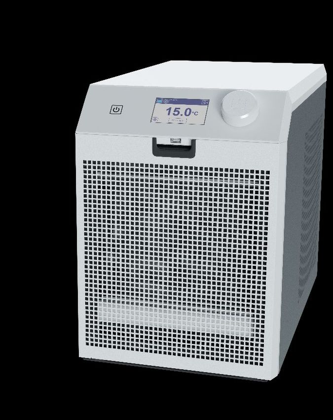
Introduction........................................................................................................................................................ 4
  General Safety Information ............................................................................................................................... 5
     Safety Recommendations ............................................................................................................................. 5
  Unpacking Your Chiller ..................................................................................................................................... 6
  Regulatory and Compliance Testing ................................................................................................................. 6
  Package Contents ............................................................................................................................................ 6
  Controls and Components ................................................................................................................................ 7
     Front View — Air-Cooled Models .................................................................................................................. 7
     Rear View — Air-Cooled Models ................................................................................................................... 7
  Quick Start ....................................................................................................................................................... 8
Installation ......................................................................................................................................................... 9
  Site Requirements............................................................................................................................................ 9
     Ambient Temperature and Relative Humidity................................................................................................. 9
     Location ........................................................................................................................................................ 9
     Clearance ..................................................................................................................................................... 9
     Electrical Power ............................................................................................................................................ 9
  Optional Signal Inputs/Outputs ....................................................................................................................... 10
     External Control / Ambient Tracking Temperature Probe ............................................................................. 10
     RS232 Serial Output ................................................................................................................................... 10
     Remote I/O Port .......................................................................................................................................... 10
     USB Serial / TMC Output ............................................................................................................................ 10
  Plumbing ........................................................................................................................................................ 10
     Process Piping ............................................................................................................................................ 10
     Drain........................................................................................................................................................... 10
     External Water Filter ................................................................................................................................... 10
     Closed System or Cooling Coil Setup .......................................................................................................... 11
     Open Bath System Setup............................................................................................................................ 11
Startup.............................................................................................................................................................. 12
  Process Coolant ............................................................................................................................................. 12
     Suitable Fluids ............................................................................................................................................ 12
     Recommended Fluids ................................................................................................................................. 13
     Fluid Compatibility Table ............................................................................................................................. 13
     Filling the Reservoir .................................................................................................................................... 13
     Electrical Power .......................................................................................................................................... 13
     Starting Process Fluid Flow......................................................................................................................... 14
Normal Operation ............................................................................................................................................ 15
  Standby Screen.............................................................................................................................................. 15
  Home Screen (Default Operation with Internal Probe Only)............................................................................. 15
     Liquid Level Sensor .................................................................................................................................... 16
     Setting a Temperature ................................................................................................................................ 16
  Access Settings and Other Functions in the Menu .......................................................................................... 17
  Selecting the Temperature Unit (°C or °F)....................................................................................................... 17
     List of Chiller Menu Parameters .................................................................................................................. 18
  Adjusting the High Pressure Bypass Setting ................................................................................................... 21
Routine Maintenance and Troubleshooting ................................................................................................... 22
  Routine Maintenance ..................................................................................................................................... 22
     Condenser, Air Vents and Reusable Filter ................................................................................................... 22
     Air Filter Access .......................................................................................................................................... 22
     Passive Filter .............................................................................................................................................. 22
     Dynamic Filter............................................................................................................................................. 23
     UV Anti-Growth Light (Optional) .................................................................................................................. 24
     Fluid Level Sensor ...................................................................................................................................... 24
     Fluid Properties........................................................................................................................................... 24
     Draining the fluid ......................................................................................................................................... 24
     Temperature Calibration ............................................................................................................................. 24
  Troubleshooting ............................................................................................................................................. 26
     Restoring Factory Default Settings .............................................................................................................. 26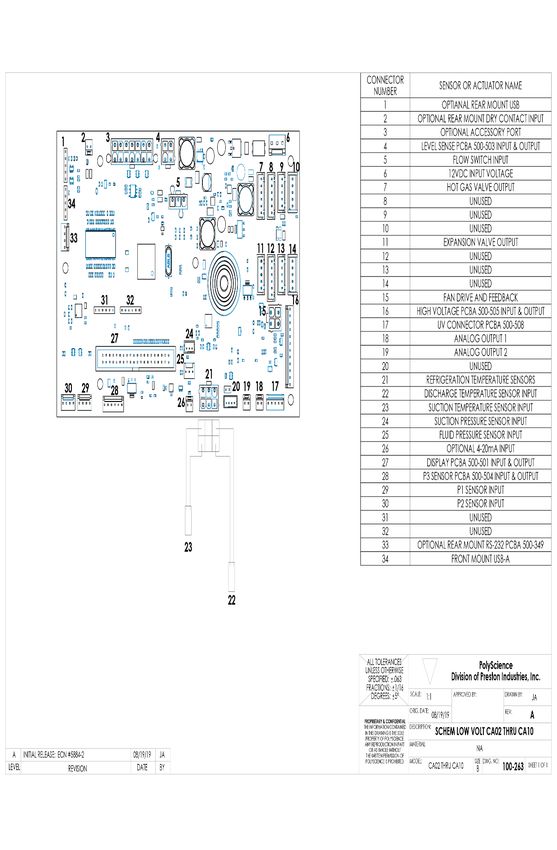
Recommended Troubleshooting Procedures ............................................................................................... 27
Display, Alarm, and Error Messages ........................................................................................................... 29
Diagnostic Mode ......................................................................................................................................... 31
Technical Information ...................................................................................................................................... 32
General Specifications (all Chillers) ................................................................................................................ 32
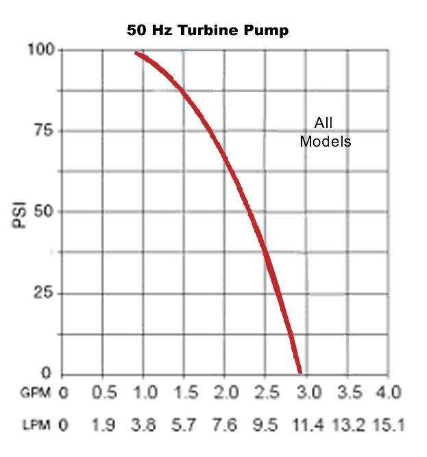
Pump Performance ........................................................................................................................................ 32
Performance Specifications — 60Hz Chillers .................................................................................................. 33
Air-Cooled 1/4-HP, 1/3-HP and 1/2-HP Chillers ........................................................................................... 33
Air-Cooled 1-HP Chillers ............................................................................................................................. 34
Performance Specifications — 50Hz Chillers .................................................................................................. 35
Air-Cooled 1/4-HP, 1/3-HP and 1/2-HP Chillers ........................................................................................... 35
Air-Cooled 1/4-HP, 1/3-HP and 1/2-HP Chillers ........................................................................................... 35
Air-Cooled 1-HP Chillers ............................................................................................................................. 36
Diagrams and Schematics .............................................................................................................................. 37
Electrical Wiring Diagram – High Voltage .................................................................................................... 37
Electrical Wiring Diagram – Low Voltage ..................................................................................................... 38
Process Flow Schematic (Air Cooled Chiller)............................................................................................... 39
Replacement Parts ......................................................................................................................................... 40
Communications ............................................................................................................................................ 43
Connector Pinout ........................................................................................................................................ 43
Serial Port Protocol Definitions and Commands .......................................................................................... 44
Certificate of Compliance................................................................................................................................ 47
Equipment Disposal (WEEE Directive) ........................................................................................................... 48
Service and Technical Support ....................................................................................................................... 48
Warranty ........................................................................................................................................................... 49
110-969
03/01/2021 3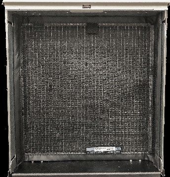
Introduction
Your Recirculating Chiller provides cooling power for demanding applications and serves as an economical
alternative to tap water cooling systems. Extremely easy to use and maintain, it combines technological
innovation with precise temperature control to deliver reliable heat removal for a wide variety of applications.

Here are some of the features that make your Chiller so user-friendly:

 •   Microprocessor-based temperature controller
 •   Large, easy to read touch screen display (temperature readout in °C or °F)
 •   Multi-Language Interface
 •   Touch keypad temperature set point adjustment
 •   Cool Command™ modulated refrigeration system for enhanced temperature stability and extended
     compressor life
 • WhisperCool® Environmental Control System with variable speed fan to reduce operational noise and
     decrease energy consumption
 •   Chillers with standard reservoir configuration feature continuous level sensing for pump protection
 •   Diagnostic Self-Test routine allows operators to test the Chiller's performance against a factory baseline
 •   USB Port for data logging
 •   Optional pumping configurations include positive displacement and turbine pump
 •   UV Anti-Growth Light (featured on certain models) inhibits biological growth in the Chiller's process fluid
 •    Self-Cleaning Dynamic Air Filter (featured on certain models) regularly scrolls condenser air filter media to
      maximize air flow and reduce maintenance
This manual is designed to guide you quickly through the process of installing and operating your Recirculating
Chiller. We recommend that you read it thoroughly before you begin.

110-969
03/01/2021                                                                                                            4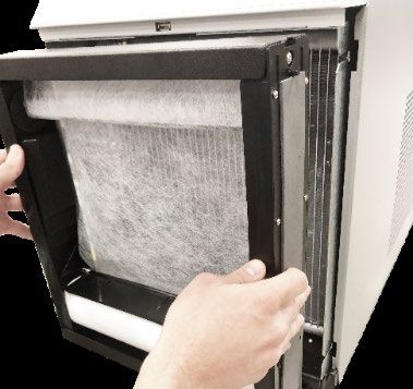
General Information
General Safety Information
When installed, operated and maintained according to the directions in this manual and common safety
procedures, your Chiller should provide safe and reliable heat removal. Please ensure that all individuals involved
in the installation, operation or maintenance of this unit read this manual thoroughly prior to working with the unit.

              This symbol alerts you to a wide range of potential dangers.

              This symbol advises you of danger from electricity or electric shock.

              This symbol marks information that is particularly important.

              This symbol indicates alternating current.

    /         These symbols on the Power Switch / Circuit Breaker indicate that they place the main power supply ON / OFF.

              This symbol on the Power Switch indicates that it places the unit in a standby mode. It DOES NOT fully
              disconnect the unit from the power supply.

              This symbol indicates a protective conductor terminal.

                    Read all instructions pertaining to safety, set-up and operation.
                    Proper operation and maintenance is the user’s responsibility.

Safety Recommendations
To prevent injury to personnel and/or damage to property, always follow your workplaces safety procedures when
operating this equipment. You should also comply with the following safety recommendations:

             • Always connect the power cord on this unit to a grounded (3-prong) power outlet. Make certain
                that the outlet is the same voltage and frequency as your unit.
             • Never operate the unit with a damaged power cord.
             • Always turn the unit OFF and disconnect Mains power before performing any maintenance or
                service.

110-969
03/01/2021                                                                                                              5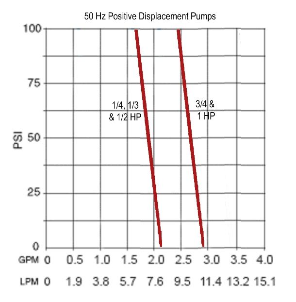
Unpacking Your Chiller
Your Chiller is shipped in a special carton. Retain the carton and all packing materials until the unit is completely
installed and working properly. Set up and run the unit immediately to confirm proper operation. Beyond one
week, your unit may be warranty repaired, but not replaced. If the unit is damaged or does not operate properly,
contact the transportation company, file a damage claim and contact the company where your unit was purchased
immediately.

               CAUTION: Keep unit upright when moving. Be sure to follow your company’s procedures and practices
               regarding the safe lifting and relocation of heavy objects.

Regulatory and Compliance Testing
Canada USA (60Hz units)
  CAN/CSA C22.2 No. 61010-1-12 — Safety Requirements for Electrical Equipment for Measurement, Control
  and Laboratory Use, Part I: General Requirements.
  CAN/CSA C22.2 No. 61010-2-010:15 - Safety Requirements for Electrical Equipment for Measurement, Control
  and Laboratory Use – Part 2-010: Particular requirements for laboratory equipment for the heating of materials
  CAN/CSA C22.2 No. 61010-2-011- 2017 Safety Requirements for Electrical Equipment for Measurement,
  Control and Laboratory Use – Part 2-011: Particular Requirements for Refrigerating Equipment.
  UL Std No. 61010-1 (2012) — Safety Requirements for Electrical Equipment for Measurement, Control and
  Laboratory Use - Part I: General Requirements.
  UL 61010-2-010:2015 - Safety Requirements for Electrical Equipment for Measurement, Control and Laboratory
  Use – Part 2-010: Particular Requirements for Laboratory Equipment for the Heating of Materials
  UL Std No. 61010-2-011 (2017) – Safety Requirements for Electrical Equipment for Measurement, Control and
  Laboratory Use - Part 2: Particular Requirements for Refrigerating Equipment.

CE (50Hz units)
  Machinery Directive 2006/42/EC
  EC Electromagnetic Compatibility Directive 2014/30/EU
  IEC 61010-1 / EN 61010-1:2010
  IEC 61010-2-011
  IEC 61326:2012 / EN 61326:2013
  RoHS Directive 2011/65/EU

Package Contents
The following items have been included with your Chiller:
  • Operator’s Manual
  • IEC Power Cord (select models)
  • Two sets of Inlet/Outlet Adapters: 1/2 inch male NPT x 1/2 inch hose barb and 1/2 inch male NPT x 5/8 inch
    hose barb (select models)

110-969
03/01/2021                                                                                                         6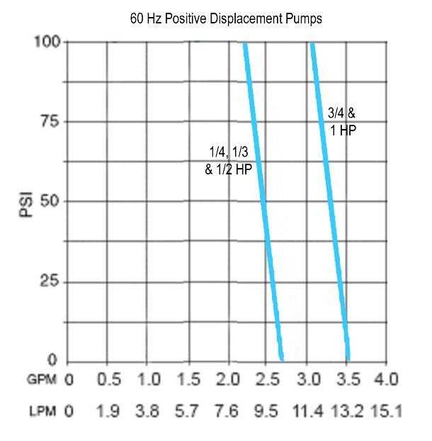
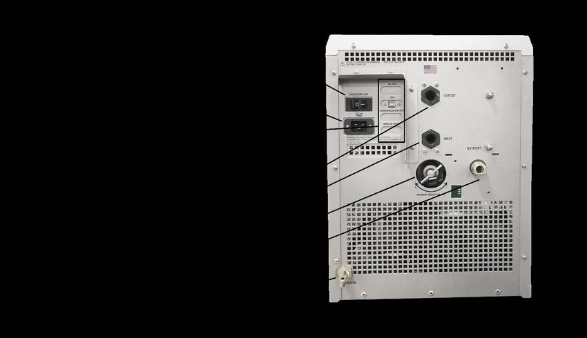
Controls and Components
Front View — Air-Cooled Models

Rear View — Air-Cooled Models

110-969
03/01/2021                       7
Quick Start
See Installation & Startup for additional information.

         All models:
   1     Connect all
         process lines

                                                              Air-Cooled Models

         Remove
         reservoir cap
   2
         and fill reservoir
         with coolant

         Connect
   3     electrical power
         cord to Mains

         Turn Power
   4     Switch / Circuit
         Breaker ON

         Press Standby
   5     Button on front
         panel

         Add coolant to
         reservoir as
   6     process lines
         fill. Replace
         cap.

                              Press "SET = " To enter Set Point Screen      Use numeric keypad to enter desired
                                                                            set point. Press  to save set point
                                                                            and return to Home Screen
         Enter
   7     temperature set
         point

110-969
03/01/2021                                                                                                        8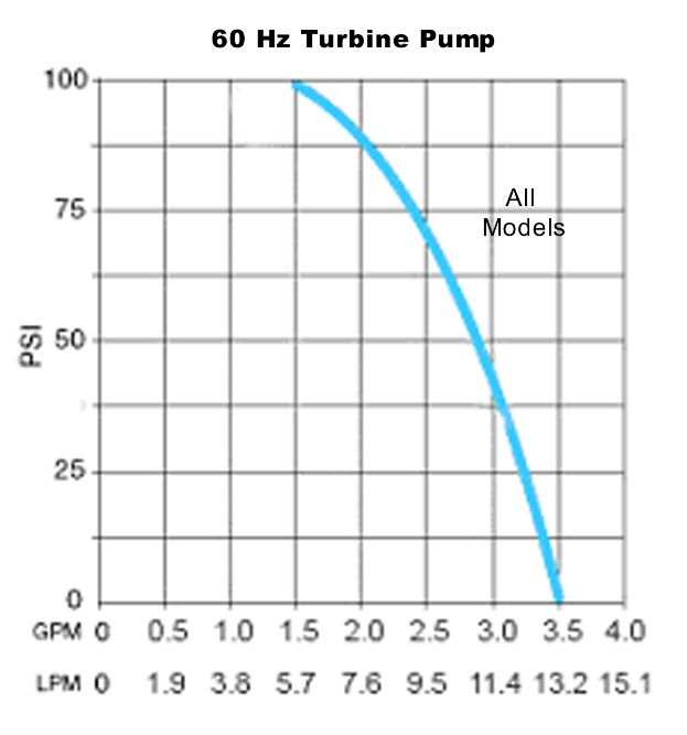
Installation

                WARNING: Be sure all power is off before proceeding.

Site Requirements
Ambient Temperature and Relative Humidity
The Chiller is designed for indoor installation in ambient temperatures between 5° and 40°C (41° and 104°F);
relative humidity should not exceed 80% (non-condensing).
Location
 • The Chiller should be installed on a strong, level surface.
 • It should be located as close as possible to the process requiring cooling.
 • It should not be installed closer than 4 feet (1.4 meters) to a heat-generating source, such as heating pipes,
     boilers, etc.
 • If possible, the Chiller should be located near a suitable drain to prevent flooding in the event of leaks.
 • Do not place it where corrosive fumes, excessive moisture, excessive dust, or high room temperatures are
     present.
 • Do not place it where access to the disconnecting device is impeded.
 • For ease of positioning and maneuverability, the Chiller is supplied with casters. The front wheels can be
     locked to keep the Chiller in place while in use.
 • To help prevent voltage drops, position the Chiller as close as possible to the power distribution panel. Avoid
     voltage drops by using a properly grounded power outlet wired with 14 gauge or larger diameter wire. The
     use of an extension cord is not recommended.

                NOTE: The Chiller may be located at a level below that of the equipment being cooled. As long as the
                process remains closed, overflow will not occur when adding cooling fluid to the Chiller reservoir.

Clearance
Adequate clearance should be allowed on the front, sides, and rear of the Chiller for access to connections and
components. The front and rear vents of the Chiller must be a minimum of 24 inches (61 cm) away from walls or
vertical surfaces so air flow is not restricted.
Electrical Power
An IEC power cord is provided with the Chiller for select models. It should be attached to the receptacle on the
rear of the enclosure. Make sure that the power outlet used for the Chiller is properly grounded and matches the
voltage and frequency indicated on the identification label on the back of the Chiller.
The use of an extension cord is not recommended. However, if one is necessary, it must be properly grounded
and capable of handling the total wattage of the unit. The extension cord must not cause more than a 10% drop in
voltage to the Chiller.

                WARNING: DO NOT plug the Chiller into the electrical outlet until the unit is ready for startup (see Startup on
                page 12).

110-969
03/01/2021                                                                                                                   9
Optional Signal Inputs/Outputs
External Control / Ambient Tracking Temperature Probe
This option allows you to control the cooling fluid temperature using an external temperature measurement
(ambient room/machine temperature or process temperature). A 9-pin connector is provided on the rear panel for
connecting the external probe.

                 NOTE: In order to minimize process disturbance when using an external temperature probe, it is
                 recommended that the external probe be connected to the unit before power is applied.

RS232 Serial Output
This option allows you to remotely control the Chiller and/or output temperature readings to an external recorder
or other auxiliary device. The maximum communications distance for Chillers equipped with the RS232 option is
50 feet (15 meters). A 9-pin D-connector is provided on the rear of the instrument enclosure for this connection.
Remote I/O Port
This option allows you to use a dry contact closure to turn the Chiller on and off. Chiller status is also available
from this port. A 15-pin D-connector is provided on the rear of the instrument enclosure for this optional
connection. See schematic at the end of this manual.
USB Serial / TMC Output
This option allows you to remotely control the Chiller and/or output temperature readings to an external recorder
or other auxiliary device. The port can be changed to behave as either a virtual com port, or as a USB TMC
device by making the appropriate selection in the Menu. A type B connector is provided on the rear of the
instrument enclosure for this optional connection.

Plumbing
Process Piping
The Chiller has two internally threaded (1/2 inch ID NPT) fittings on the rear of the instrument housing for the
process water connections. Two sets of adapters (1/2 inch ID and 5/8 inch ID) are supplied with the unit for
connecting these fittings to the process piping.
To maintain a safe workplace and avoid leaks, special care should be taken when choosing hoses and
connectors for the Chiller. It is the user’s responsibility to ensure that the tubing and fittings connected to the
Chiller are compatible with the fluid, temperature, and pressure being used.
  • Pressure Ratings — Hoses should be able to withstand the largest pressure that they will encounter.
    For “P” Series (positive displacement pump) and “T” Series (turbine pump) Chillers, this is 100 psi (689 kPa).
  • Flexible Tubing — Avoid tubing that will expand and take up fluid volume when operating at the desired
    pressure.
  • Hose Diameter — Process piping/hosing with a diameter smaller than ½ inch ID can be used if desired.
    However, keep in mind that using smaller diameter hosing increases pressure in the circulating system.
  • Couplings and Clamps — The use of screw-tightened hose clamps is necessary on all joints to insure good,
    tight connections. Quick connectors are not recommended as they have the potential for restricting flow rate.
Drain
A connection is provided for the reservoir’s gravity drain. It should be piped to a drain or receptacle positioned
below the bottom of the reservoir. If a receptacle is used, be sure it is of sufficient volume to hold all the water in
the reservoir, process and process lines. This will also drain the fluid from the pump.
External Water Filter
An optional water filter is available that can be connected to the Chiller’s fluid inlet or fluid outlet. Consult supplier
for additional information.

110-969
03/01/2021                                                                                                                10
Closed System or Cooling Coil Setup Connect the Chiller’s inlet and outlet to the external apparatus with hoses or pipes. The direction of the flow through the system can be controlled by the way the connections are made. Fluid is drawn into the Chiller through the “Inlet” connection; fluid is pumped out of the Chiller through the “Outlet” connection. Open Bath System Setup Position the external tank at least two feet (0.6 meter) above the Chiller’s inlet. Install a shutoff valve on both the inlet and outlet of the Chiller. Place the valves in the closed position. Connect the shutoff valves to the external tank using the tubing of equal diameter (1/2 inch minimum) and length. Use the same size fittings on both the inlet and outlet; this will ensure a balanced flow. Cut the external end of the suction (inlet) tube into a “V” shape so that the tube will not seal itself against the wall of the external tank. Both the pressure and suction tubing should be securely fastened to the external tank to prevent movement during use. When using flexible tubing, the suction (inlet) tubing must have a wall thickness that will not collapse under vacuum, particularly when going around bends. Fill the external bath (see Startup, Process Coolant on page 12 for suitable fluids). Fill the Chiller reservoir to the bottom of the reservoir's fill port neck and install the cap. Tighten the cap until it is securely sealed. 110-969 03/01/2021 11
Startup
Process Coolant
Your Chiller must be operated with fluid in the reservoir. Always fill the reservoir before operation, to prevent
damage to your unit. This section will provide you information on the selection and use of compatible fluids for
your specific process.

Suitable Fluids

                WARNING: Only use fluids that will satisfy safety, health, and equipment compatibility requirements.

                WARNING: Do not use caustic, corrosive, or flammable fluids.

                WARNING: Operation below 10°C (50°F) requires antifreeze in the circulation fluid.

                CAUTION: Always select a fluid that is compatible with the Chiller’s wetted parts (brass, stainless steel,
                polyethylene, EPDM rubber, and nylon).

                NOTE: For storage purposes, a very small amount (below 25mL) of laboratory grade propylene glycol is added
                to the unit to avoid freezing damage to the pump. While this small amount will have no impact when mixed with
                other fluids, please refer to Routine Maintenance and Troubleshooting, Draining the fluid on page 24 for
                information on draining the pump.

                WARNING: Do not use the following fluids:
                  • Automotive antifreeze with additives**
                  • Hard tap water**
                  • Deionized water with a specific resistance > 1 meg ohm (except units with the DI water compatible
                      plumbing
                  •   Any flammable fluids
                  •   Concentrations of acids or bases
                  •   Solutions with halides: chlorides, fluorides, bromides, iodides or sulfur
                  •   Bleach (Sodium Hypochlorite)
                  •   Solutions with chromates or chromium salts
                  •   Glycerin
                  •   Syltherm fluids
                ** Additives or mineral deposits can adhere to internal components. If deposits are allowed to build up damage may result
                to components such as the pump or heat exchanger. Higher temperatures and higher concentrations of additives can hasten
                deposit build up.

110-969
03/01/2021                                                                                                                            12
Recommended Fluids
We recommend the following fluids be used with Chillers. Always verify fluid compatibility with the application in
which the Chiller will be used and all wetted parts.
Fluid Temperature Range Recommended Maintenance
polyclear MIX 30 PLUS
(distilled water plus clarifier and +10° to +90°C (+50° to +194°F)
Verify fluid level monthly or more
corrosion inhibitor)
frequently per application needs.
polycool MIX -25 Replace fluid every 3 months.
(50/50 mix distilled water and -25° to +80°C (-13° to +176°F)
ethylene glycol)
Fluid Compatibility Table
Material of Construction
Braided Stainless
Buna N Viton® Nylon Brass
Fluid Teflon® Steel
Tubing Tubing Fittings Fittings
Tubing Fittings
polycool MIX -25
(50/50 premix of
distilled water and
ethylene glycol)
polyclear MIX 30 PLUS
(distilled water plus
clarifier and corrosion
inhibitor)
polycool EG -25
concentrate
(ethylene glycol)
polycool PG -20
concentrate
(propylene glycol)
= compatible
The most common and acceptable coolant is a mixture of 50% distilled water and 50% ethylene glycol (laboratory
grade), such as premix polycool MIX -25. This fluid mix will provide the best results for set points between -25°
and +80°C (-13° and +176°F). Ethylene glycol helps lubricate pump seals and protects against freezing (the fluid
temperature inside the Chiller may be below freezing even if the temperature at the outlet is over 0°C / +32°F).
We offer ethylene glycol (polycool EG -25) and propylene glycol (polycool PG -20) that can be mixed with an
equal volume of distilled water to create a 50/50 water/glycol mix. Also available is a fluid clarifier to control
inanimate organic particles (polyclean CLARIFIER).
Filling the Reservoir
Remove the filler cap from the reservoir and, using a funnel, add fluid until it reaches the bottom of the reservoir’s
fill port. Once the reservoir is full, remove the funnel but do not replace the cap at this time.
Electrical Power
Plug the Chiller’s power cord into an appropriate electrical outlet.
Place the Circuit Breaker/Power Switch on the rear of the instrument enclosure in the “On” position. A standby
screen will appear on the Chiller's display.
110-969
03/01/2021 13Starting Process Fluid Flow
NOTE: When adding fluid to the unit for the first time, prime the pump by pressing the Standby Button
“On” and letting the Chiller run for 3 seconds and then pressing the Standby Button again to turn power
“OFF”. Repeat this “On” and “Off” procedure three times.
Press the Standby Button on the front panel. The system startup sequence will begin and proceed as follows:
1. The pump will turn on and fluid will begin circulating through the system. The Home Screen will now be
shown on the display. Fifteen to twenty seconds after power up, the compressor will begin operating.
2. Check for leaks.
3. With the pump running, the reservoir’s fluid level will drop as the process and/or process cooling lines fill
with fluid. Add fluid as follows:
4. Closed Systems: Slowly add fluid to the reservoir until the liquid level remains stable
5. Open Bath Systems:
A. Open the inlet and outlet valves on the Chiller; the suction created by the pump should begin
drawing fluid through the inlet tubing into the Chiller reservoir.
B. Once flow is established (no air bubbles in inlet tubing), close the inlet and outlet valves and
turn the Chiller “Off”.
C. Remove the reservoir cap and check the level of the fluid in the reservoir. Add coolant until it is
level with the bottom of the reservoir's fill port neck.
CAUTION: Always close the inlet and outlet valves before turning power to the Chiller ”Off” or removing
the reservoir cap to prevent the external reservoir from flooding the Chiller.
D. Replace the reservoir cap, open the inlet and outlet valves, and restart the Chiller.
E. Observe the liquid level in the external reservoir; adjust the valve on the Chiller outlet as required
to maintain a stable fluid level.
CAUTION: When running an open loop system for extended periods, the fluid level in the Chiller
reservoir should be checked periodically to avoid low fluid conditions.
To check the reservoir fluid level, close the inlet and outlet valves, turn the Chiller ‘off’, and remove
the reservoir cap. Slowly open the inlet and outlet valves and allow fluid to drain from the external
reservoir into the Chiller reservoir. Close the valves when the fluid level within the Chiller reservoir
reaches the top of the filler neck. Add fluid to the external reservoir as required. Replace the
reservoir cap, open the inlet and outlet valves, and turn the Chiller back on.
110-969
03/01/2021 14Normal Operation
This section provides information on all basic functions and normal operations involved in the daily use of your
Chiller. Please familiarize yourself with all screens and functions before operating.
SPECIAL FEATURE: Air-cooled Chillers are equipped with the WhisperCool® Environmental Control
System, which controls fan speed based on the heat load. You will notice the fan speed changing gradually
during operation. This is especially beneficial in an environment where a low noise level is desirable.
Standby Screen
After energizing the Chiller, the Chiller will enter Standby Mode. In Standby, the fluid pump, refrigeration
compressor, and condenser fan are all disabled. You may adjust Chiller settings in this mode by pressing from
this screen. Press the Chiller's Standby Button to begin operation. You will be taken to the Home Screen, and the
Chiller's fluid pump, refrigeration and fluid temperature control functions will all be enabled.
Home Screen (Default Operation with Internal Probe Only)
The Chiller's Home Screen displays the readout of fluid temperature, temperature unit of measure, temperature
set point, Chiller fluid pressure at the outlet, reservoir fill level, and airflow status. If there is an active Alarm or
Warning, it will be displayed in the Status Bar.
Press the Set Temperature Button to adjust the fluid temperature set point.
Press the Settings Button to adjust other operating parameters such as Fahrenheit/Celsius selection.
110-969
03/01/2021 15Liquid Level Sensor The reservoir icon at the top of the Home Screen indicates reservoir fill level. When the fluid display is orange, the fill level is lower than normal, but the pump and compressor will continue to run. When the fluid display is red, the pump and compressor will stop running because the reservoir fluid level is critically low. If the reservoir fluid level is low, check for leaks and re-fill the reservoir. Setting a Temperature Press the Set Button from the Home Screen. Alternatively, you may adjust the set point from the Menu. A numeric keypad will be displayed on the screen. Enter the desired temperature set point. The value will be reflected in the left box. If you wish to set a value less than zero, press the +/- button to switch between positive and negative set point values. The set point limits are displayed underneath the set point. Values outside of the set point limits will not be accepted. You may also use the arrows to raise or lower the set point without using the number pad. Acknowledge and save the selection by pressing , or discard the selection by pressing . 110-969 03/01/2021 16
Access Settings and Other Functions in the Menu

Access the Menu by pressing       from the Home Screen or Standby Screen. In the menu, you will see the active
settings for various parameters such as Temperature Units, Display Language, Set Point Limits, Alarm Settings,
and Maintenance Reminders. Data Logging, Diagnostics and Chiller Self Test are all accessible from the Menu.

Press any of the Menu items to access and adjust functions associated with that item. Use the up and down arrow
keys to display additional Menu items. Press   to return to the Home Screen.

Selecting the Temperature Unit (°C or °F)

Access the Menu by pressing        from the Home Screen or Standby Screen. The active Temperature Units
selection will be displayed in the menu. Press "TEMPERATURE UNITS" to access the Temperature Units
Selection Screen. Press the desired selection. Acknowledge and save the selection by pressing , or discard the
selection by pressing .

110-969
03/01/2021                                                                                                   17
List of Chiller Menu Parameters
 Menu Items and Settings          Description
 User Settings                    Access User Settings Menu
 Setpoint                         Adjust the Chiller's set temperature
 Temperature Units                Select Celsius or Fahrenheit display
 Pressure Units                   Select PSI or KPA display
 Air Filter                       Access air filter maintenance screen. Use this screen to setup auto advance
                                  intervals for the Dynamic Air Filter, or maintenance reminders for the passive
                                  air filter.

 Fluid Maintenance                Access fluid maintenance screen. Use this screen to set maintenance
                                  reminders for fluid and water filter.

 Setpoint Limits                  Set the high and low limits for the Chiller set temperature

 Temperature Alarms               Continuous Chiller operation outside of these settings will cause the Chiller to
                                  alarm. These settings can be used to protect equipment connected to the
                                  Chiller, or the fluid, from extreme temperatures.

 Max Fluid Pressure               Continuous operation above this setting will cause the Chiller to alarm. This
                                  setting can be used to protect equipment connected to the Chiller.

 Specific Heat Capacity           If the Chiller's process fluid has a specific heat that is vastly different than
                                  water, temperature stability may be affected. The operator can improve
                                  stability by adjusting the Chiller's Specific Heat Capacity setting to match that
                                  of the fluid.

 Remote Control Switch            The operator may choose how a remote contact is used to start and stop the
                                  Chiller. The operator can choose to disable remote control, start the Chiller
                                  when the remote contact opens, or start the Chiller when the remote contact
                                  closes.

 External Monitor / Control       This setting determines how a remote P2 probe or the internal ambient P3
                                  probe are used. When only the ambient P3 probe is present with no external
                                  probe, the operator may use "P3 SETPOINT MODE" so that the set
                                  temperature tracks the ambient temperature. When a remote P2 probe is
                                  connected, the operator may select the following additional modes:
                                  "MONITOR MODE" displays the P2 reading without using it for control.

                                  "CONTROL MODE" uses the external P2 sensor as the process temperature.
                                  In Control Mode, the Chiller will act to maintain the P2 reading at setpoint.
                                  This will typically be used when the Chiller is connected to reactors, jacketed
                                  vessels, heat exchangers, and similar equipment.

                                  "P2 SETPOINT MODE" will use the external P2 sensor to determine set
                                  temperature. This is commonly used for ambient tracking applications.

 Setpoint Offset                  This setting is only used in P2 SETPOINT MODE or P3 SETPOINT MODE.
                                  The Setpoint offset is added to the P2 or P3 reading, resulting in the effective
                                  set temperature. The Setpoint Offset may be positive or negative.

110-969
03/01/2021                                                                                                            18
Menu Items and Settings Description
| P1 – P2 | Max This setting is only used in CONTROL MODE when controlling with an
external P2 sensor.
This setting helps establish the cooling/heating rate when the remote
temperature control probe is being used. The higher the setting, the more
rapidly the Chiller will achieve the external temperature set point. Low
differential temperature settings minimize the amount of temperature
overshoot/undershoot that occurs when the measured external temperature
reaches the external set point temperature.
Calibration OFFSET P1 INTERNAL This menu item allows you to adjust the Chiller’s internal temperature reading
to match that of a traceable standard.
Calibration Offset P2 External This menu item allows you to adjust the Chiller’s external temperature reading
to match that of a traceable standard.
Maintenance Reminder The operator may set a periodic maintenance reminder for any purpose.
Diagnostics Enter Diagnostics menu. View operating conditions, including compressor
and pump current draw, line voltage and frequency, ambient temperature,
cumulative running time, number of on/off cycles, fluid level, remote control
switch status, and firmware version. From the Diagnostics Menu, the operator
may run a Diagnostic Self Test, View the last Diagnostic Self Test, and
perform a Factory Reset to default settings.
User Settings Description
Language Selection Sets the language used throughout the Chiller's interface.
Data Log Sets the frequency at which data is logged to a USB drive
Fluid Level Sensor Enable Certain fluids and operating points may affect the performance of the level
sensor. In this case the level sensor may be disabled. If the sensor is disabled,
the operator must be responsible for maintaining fluid level.
Buzzer Enabled The operator may disable the audible indication of alarms.
USB Device Mode When fitted with the optional USB-B port, this setting will determine whether the
port acts as a USB Virtual Serial Port or a USBTMC device.
Screen Brightness The operator may adjust the screen's brightness level
110-969
03/01/2021 19Dynamic Air Filter Management
Your Chiller may be equipped with a Dynamic Air Filter that will regularly scroll fresh filter material in front of the
refrigeration condenser to ensure optimal airflow and cooling performance. To check the remaining filter life or
change the scroll rate, press "AIR FILTER" from the Menu.
On this screen, you can change the frequency of filter scrolling. 30 days is the default setting. Decreasing the
number of days will make the filter scroll more frequently and stay cleaner in more challenging environments. You
may also advance the filter manually by pressing the "ADVANCE FILTER" option.
NOTE: Manual advancing of the filter will reduce maximum filter life.
When a new Dynamic Air Filter cartridge is installed, a pop-up will be shown. Selecting "YES" will reset the Filter
Life counter. Pressing the "NEW FILTER INSTALLED" button will also reset the counter.
110-969
03/01/2021 20Adjusting the High Pressure Bypass Setting
The Chiller incorporates a bypass pressure regulating valve to limit the outlet fluid pressure of the Chiller. This
valve is adjustable and is accessible from outside of the Chiller. It is located on the rear of the Chiller housing.
CAUTION: Discharge of high pressure fluid and fluid spills may result from over-pressurization. Personal
safety hazard and damage to equipment, material, or facilities may result from the discharge of high pressure
fluid and spills. The pressure regulator should only be adjusted by personnel familiar with the piping, hoses,
equipment that are connected to the Chiller, and their maximum working pressures.
The high-pressure bypass is adjusted as follows:
1. Completely block the Chiller’s outlet flow. This should cause the outlet pressure to rise.
2. Rotate the handle on the pressure valve until the desired maximum pressure setting is shown on the Home
Screen.
110-969
03/01/2021 21Routine Maintenance and Troubleshooting Routine Maintenance The Chiller is designed to require a minimum of periodic maintenance. Chillers equipped with Turbine or Positive Displacement Pumps do not require lubrication. For convenience, a maintenance reminder can be set on the unit. This can be found by navigating to the Maintenance Reminder item in the menu. Select one of the preset values, or create your own using the Custom option. Press to reset an existing timer. To create a custom reminder, select the button marked "---" and enter a value from 1 up to 365 days. Once you have selected a custom value, the "---" value will be replaced with the selected value. Select that button again to choose a different custom maintenance interval. Condenser, Air Vents and Reusable Filter To keep the system operating at optimum cooling capacity, the condenser, the air vents, and reusable filter should be kept free of dust and dirt. They should be checked on a regular basis and cleaned as required. Air Filter Access The Chiller will be equipped with either a passive or a dynamic air filter. To access either filter, grasp the handle at the top of the Chiller's front access panel and pull outwards. The filter is located behind the panel. Passive Filter This filter should be checked on a regular basis and cleaned as required. Use a mild detergent and water solution to wash off any accumulated dust and dirt. Rinse and dry thoroughly before reinstalling. 110-969 03/01/2021 22
Dynamic Filter
The display will indicate if the filter requires replacement. To change the filter, pull the cartridge out and make
note of the position of the cartridge's electrical connector. Align the electrical connector of the new cartridge so
that it is at the top of the cartridge and is facing in towards the condenser coil. Insert the new cartridge and
replace the front cover. Refer to the "Dynamic Air Filter Management" section on page 20 for more information.

                NOTE: A Dynamic Filter may be purchased as an optional upgrade if the Chiller is fitted with a Passive Filter.
                Remove the Passive Filter, if necessary, prior to installation of the Dynamic Filter.

                                              Hold the filter cartridge vertically.

                                        Align the side pegs with the slots in the metal.

                                   Apply gentle pressure and push the cartridge in evenly.

              Pull down slightly at the end to lock the pegs into the notch. This will ensure proper connectivity.

                NOTE: Improper installation of the filter will prevent the automatic cleaning from working correctly. Always
                ensure that the "AUTO ADVANCE FILTER INSTALLED" prompt appears when changing the filter to ensure
                proper connection with the Chiller.

110-969
03/01/2021                                                                                                                 23
UV Anti-Growth Light (Optional)
Certain Chillers are equipped with a UV Anti-Growth light to inhibit the growth of biologicals in the fluid stream. The
light will be energized while the pump is running, and an indicator will be shown on the Chiller's Home Screen.
CAUTION: The UV light is enclosed in a shroud designed to block UV rays from being emitted. Do not use the
UV light if the enclosure has been damaged, modified, or otherwise tampered with.
Fluid Level Sensor
Your Chiller is equipped with a sensor that continuously monitors fluid level in the reservoir. The fluid level will be
shown on the Home Screen. Generally, fluid should be added whenever the display fluid level indicates “LOW
FLUID LEVEL”.
Fluid Properties
The circulating fluid in your Chiller is the vital to the cooling system. If you are using an antifreeze fluid, it should be checked
regularly to ensure that it hasn't lost any of its cooling and/or antifreeze properties. In certain applications, dirt and other
particulate can make its way into the circulating fluid of your Chiller. This is bad for the Chiller, especially for the pump. If large
amounts of debris are present the fluid should be drained and the Chiller flushed.
Draining the fluid
Disconnect the Chiller from the process, aim the outlet tube down a drain or into a collection container, and pump the fluid out
following instructions on draining the fluid.
1. Ensure the pump is not run dry.
2. Flush the system with clean tap water to wash out remaining deposits. Do not use hard water or water with solid
particulates to flush the system. If clean tap water is not available, use distilled water.
3. It may be necessary to flush abundantly with clean tap water first and then run a longer closed cycle clean up with
distilled water.
4. If algae growth is present, run a closed cycle (connect a hose between the inlet and the outlet to circulate the fluid
inside the chiller) with polyclear Mix 30 PLUS.
Once the system is clean, reconnect the chiller to the process and fill the reservoir with clean fluid. Turn the Chiller on, and
continue to fill until the fluid returns to the reservoir.
Temperature Calibration
At times, there may be a minor temperature difference between the Chiller’s displayed temperature and the actual
temperature as determined by a certified temperature measurement device. There may also be situations where
you want the displayed temperature to match a particular value to have standardization between different
instruments. These adjustments can be performed using the Chiller’s internal and/or external temperature
calibration offset functions.
Diagnostic Self Test
You may periodically wish to check the performance of your Chiller against its original metrics. To start the
Diagnostic Self Test, select "DIAGNOSTICS" from the main menu. In the Diagnostics menu, select "RUN
DIAGNOSTIC SELF TEST" and follow the on-screen prompts. If you wish to save your test data, you may insert a
USB Storage Device in the front port at the beginning of the test process.
110-969
03/01/2021 24A series of prompts will guide you through the process. The Diagnostic Self Test process will take approximately
20 minutes. During this time, pump flow stop and temperature control to your process will be interrupted.
CAUTION: Do not start the Diagnostic Self Test if the equipment or process being cooled by the Chiller is
running or if it may start. Damage may result if the equipment being cooled is allowed to run during a
Diagnostic Self Test.
Once the Diagnostic Self Test has stopped pump flow, you will be asked to connect a short piece of hose (about
1m or 3.3ft) between the inlet and outlet of the Chiller. This allows for Chiller performance to be measured in
isolation from external equipment or long lengths of process tubing.
NOTE: If you do not connect the inlet directly to the outlet, the results of the Diagnostic Self Test may not be
valid.
Test progress will be indicated on screen:
110-969
03/01/2021 25Troubleshooting
Restoring Factory Default Settings
Many problems can be resolved by restoring the factory defaults. If this solves the problem, be careful when
restoring your operational settings in order not to repeat the problem.
Factory Default settings can be restored through the Menu Screen. The Chiller must be in Standby in order to
restore factory defaults.
In the main menu, select "DIAGNOSTICS"
Select "FACTORY RESET"
At the prompt, select "YES" to reset defaults.
110-969
03/01/2021 26Recommended Troubleshooting Procedures
WARNING: Refer servicing to qualified service personnel.
WARNING: When electrical power is ON, dangerous voltages exist within chassis components. Use extreme
care when measuring voltages on live circuits.
Problem Possible Causes Corrective Action
Unit does not run No power to unit Check that the electrical cord is secure and connected
(display is blank) to an operating electrical outlet.
Check that Power Switch / Circuit Breaker on rear of
unit is ON.
Unit does not run Unit in Standby mode Press Standby Button on front panel.
(display shows "Press to
start")
No fluid circulation Insufficient fluid in reservoir Add fluid to reservoir.
Blockage in circulating system Remove blockage.
Pump is not operating Check fuse and replace as necessary. Check for
electrical short circuits before replacing fuse.
Replace pump.
Insufficient circulation Fluid viscosity too high Replace with lower viscosity fluid.
External tubing diameter too Replace with larger diameter tubing.
small
Restrictions in fluid lines Check and correct as required.
Low line voltage Check and correct as required.
110-969
03/01/2021 27Problem Possible Causes Corrective Action
Unit does not cool or cooling Dust build up on air filter or Clean air filter and/or condenser as required.
is insufficient condenser (air-cooled models)
Blocked air ventilation screens Remove blockages as required.
(air-cooled models)
Excessive heat load Check that heat load does not exceed capacity of
Chiller; correct as required.
Ambient air temperature too Decrease ambient air temperature.
high
Low or high line voltage (should Check and correct as required.
be within +/- 10% of nameplate)
Blown fuse
Check fuse and replace as required. Check for electrical
Faulty temperature sensor short circuits before replacing fuse.
Check the temperature sensor readings (see
“Diagnostic Mode” on page 43). If any of these
temperature readings is "–", the sensor needs to be
replaced.
Perform a Diagnostic Self Test (refer to "Diagnostic Self
Test" on page 24).
110-969
03/01/2021 28Display, Alarm, and Error Messages
Fault Code for
Error Device
Warnings and Faults Corrective Actions Remote
Message Behavior
Communications
DISCHARGE
TEMPERATURE Discharge temperature Replace the discharge
Warning only 1
SENSOR sensor has failed. temperature sensor
FAILURE
SUCTION
Compressor,
PRESSURE Suction pressure sensor has Replace the suction
fan, and pump 2
SENSOR failed. temperature sensor
are turned off.
FAULT
Compressor,
P1 temperature sensor has Replace the internal fluid
P1 FAILURE fan, and pump 3
failed. temperature sensor
are turned off.
Check connection
Compressor,
P2 temperature sensor has
P2 FAILURE fan, and pump 4
failed. Replace the external
are turned off.
temperature sensor
Compressor,
P3 temperature sensor has Replace the P3 sensor
P3 FAILURE fan, and pump 5
failed assembly
are turned off.
SETPOINT
Temperature set point is Lower the set point or raise
ABOVE HIGH
higher than the high the High Temperature Warning only 6
TEMPERATURE
temperature limit. Alarm
SETTING
SETPOINT
Temperature set point is
BELOW LOW Raise the set point or lower
lower than the low Warning only 7
TEMPERATURE the Low Temperature Alarm
temperature limit.
SETTING
Check the fluid connections
Liquid level in the reservoir Compressor,
LOW FLUID for leaks
is below 35% for over 10 fan, and pump 8
LEVEL
seconds. are turned off.
Add fluid to the reservoir
Check the fluid connections
LEVEL LESS Compressor,
Fluid level is less than 35% for leaks
THAN 35% ON fan, and pump 9
on startup.
STARTUP remain off.
Add fluid to the reservoir
Check pump fuse, and
replace as necessary
Internal fluid flow has fallen Check that the fluid being
Compressor,
LOW FLUID below the factory used is appropriate for the
fan, and pump 10
FLOW determined minimum rate for operating temperature
are turned off.
more than 10 seconds.
Check that the stepper
motors are functioning
properly
Check process fluid lines
for restrictions
Fluid outlet pressure has
Increase the high fluid Compressor,
HIGH FLUID exceeded the high pressure
pressure alarm setting fan, and pump 11
PRESSURE limit for more than 10
are turned off.
seconds.
Increase the output
regulated pressure valve
setting (if applicable)
Fluid outlet pressure has Check the pump fuse
Compressor,
LOW FLUID fallen below the low
fan, and pump 12
PRESSURE pressure limit for more than Lower the low fluid
are turned off.
10 seconds. pressure limit
110-969
03/01/2021 29Fault Code for
Error Device
Warnings and Faults Corrective Actions Remote
Message Behavior
Communications
Check the compressor fuse
Compressor,
Fluid temperature is higher Check that the stepper
HIGH FLUID and fan are
than the high temperature motors are functioning 13
TEMPERATURE turned off; pump
limit value. properly
remains on.
Raise the high limit
Check that the stepper
Compressor,
Fluid temperature is lower motors are functioning
LOW FLUID and fan are
than the low temperature properly 14
TEMPERATURE turned off; pump
limit value.
remains on.
Lower the low limit
FILTER MOTOR Dynamic air filter motor has Replace dynamic air filter
Warning only 15
FAILURE failed. assembly
MAINTENANCE Maintenance reminder timer
Reset as necessary Warning only 16
REMINDER has expired.
CHECK FILTER External fluid filter timer has Check the external fluid
Warning only 17
REMINDER expired. filter and replace as needed
REPLACE
Fluid replace timer has
FLUID Change the fluid Warning only 18
expired.
REMINDER
MANUAL AIR
FILTER Manual air filter timer has
Clean the air filter Warning only 19
REPLACEMENT expired
REMINDER
AUTO
ADVANCE Automatic air filter removed Replace the dynamic air
Warning only 20
FILTER from unit. filter assembly
REMOVED
UV LED
UV module has failed. Replace the UV module Warning only 21
FAILURE
110-969
03/01/2021 30You can also read