ALIBI IP Camera Software User Manual
←
→
Page content transcription
If your browser does not render page correctly, please read the page content below
ALIBI™ IP Camera
Software User Manual
Products: ALI-IPU Series, ALI-IPV Series, ALI-IPZ5030 Series cameras

PLEASE READ THIS MANUAL BEFORE USING YOUR CAMERAS, and always follow the instructions for safety
and proper use. Save this manual for future reference.

                                                                                      ALI-IPU-V30xxR_CM
                                                                                                  7/30/14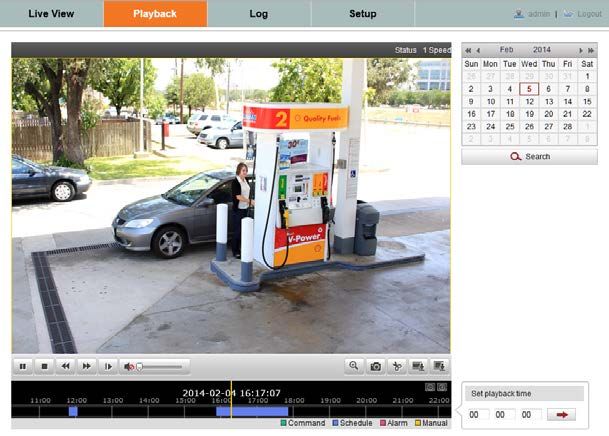
FCC Caution: To assure continued compliance, use only shielded interface cables when connecting to computer or
peripheral devices. Any changes or modifications not expressly approved by the party responsible for compliance could
CAUTION void the user’s authority to operate this equipment.
This equipment has been tested and found to comply with the limits for a Class “A” digital device, pursuant to Part 15
of the FCC Rules. These limits are designed to provide reasonable protection against harmful interference when the
NOTE equipment is operated in a commercial environment. This equipment generates, uses, and can radiate radio frequency
energy and, if not installed and used in accordance with the instruction manual, may cause harmful interference to radio
communications.
LEGAL NOTICE
Observint Technologies (Observint) products are designed to meet safety and performance standards with the use of
specific Observint authorized accessories. Observint disclaims liability associated with the use of non-Observint
authorized accessories.
The recording, transmission, or broadcast of any person’s voice without their consent or a court order is strictly
prohibited by law.
Observint makes no representations concerning the legality of certain product applications such as the making,
transmission, or recording of video and/or audio signals of others without their knowledge and/or consent. We
encourage you to check and comply with all applicable local, state, and federal laws and regulations before
engaging in any form of surveillance or any transmission of radio frequencies.
Alibi and the Alibi logo are trademarks of Observint.
Microsoft, Windows, and Internet Explorer are either registered trademarks or trademarks of Microsoft Corporation in
the United States and/or other countries. Android is a trademark of Google Inc. Use of this trademark is subject to
Google Permissions. Apple, iPhone, iPod touch, and iPad are registered trademarks of Apple Inc.
Other trademarks and trade names may be used in this document to refer to either the entities claiming the marks
and names or their products. Observint disclaims any proprietary interest in trademarks and trade names other than
its own.
No part of this document may be reproduced or distributed in any form or by any means without the express written
permission of Observint, Inc.
© 2014 by Observint Technologies. All Rights Reserved.
11000 N. Mopac Expressway, Building 300, Austin, TX 78759
For Sales and Support, contact your distributor.
ii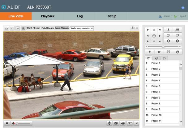
SAFETY INSTRUCTIONS

Regulatory information
FCC information

FCC compliance: This equipment has been tested and found to comply with the limits for a digital device, pursuant to part 15 of the
FCC Rules. These limits are designed to provide reasonable protection against harmful interference when the equipment is operated
in a commercial environment. This equipment generates, uses, and can radiate radio frequency energy and, if not installed and used
in accordance with the instruction manual, may cause harmful interference to radio communications. Operation of this equipment
in a residential area is likely to cause harmful interference in which case the user will be required to correct the interference at his
own expense.

FCC conditions

This device complies with part 15 of the FCC Rules. Operation is subject to the following two conditions:
1. This device may not cause harmful interference.
2. This device must accept any interference received, including interference that may cause undesired operation.

Preventive and Cautionary Tips
Before connecting and operating your cameras, please be advised of the following:
•    Ensure environmental conditions meet factory specifications.
•    Major shocks or jolts to the unit as a result of dropping it may cause damage to the sensitive electronics within the unit.
•    Use the device in conjunction with an UPS if possible.

Safety Instructions
Read these instructions and keep them in a safe place for future reference.
•    Please refer all work related to the installation of this product to qualified service personnel or system installers.
•    Do not operate the appliance outside of its specified temperature, humidity or power source ratings.
•    Install the unit away from heat sources such as radiators, heat registers and stoves.
•    Installation of the unit near consumer electronics devices, such as stereo receiver/amplifiers and televisions, is permitted as
     long as the air surrounding the terminal does not exceed the above mentioned temperature range.
•    Handle the camera with care. Do not drop or shake, as this may damage it.
•    Do not use strong or abrasive detergents when cleaning the surfaces of this product. When dirt is hard to remove, use a mild
     detergent and wipe gently.
•    Save your system configuration.
•    Distributing, copying, disassembling, reverse compiling, reverse engineering, and exporting, in violation of export laws, the
     software provided with this product is expressly prohibited.

                                                                         ALIBI™ IP Camera Software User Manual                         iii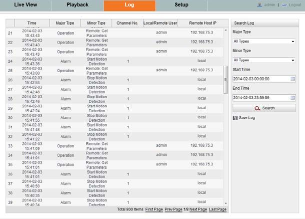
TABLE OF CONTENTS

Table of Contents
SECTION 1         Overview . . . . . . . . . . . . . . . . . . . . . . . . . . . . . . . . . . . . . . . . . . . . . . . . . . . . . . . . . . . . . . . . . . . . . . . . . . . i
                  1.1 Typical application configurations. . . . . . . . . . . . . . . . . . . . . . . . . . . . . . . . . . . . . . . . . . . . . . . . . . . . . . . i
                     1.1.1 Camera is managed by an NVR . . . . . . . . . . . . . . . . . . . . . . . . . . . . . . . . . . . . . . . . . . . . . . . . . . . . 2
                     1.1.2 Camera uses network device for video storage. . . . . . . . . . . . . . . . . . . . . . . . . . . . . . . . . . . . . . . 2
                     1.1.3 Camera is managed by a VMS . . . . . . . . . . . . . . . . . . . . . . . . . . . . . . . . . . . . . . . . . . . . . . . . . . . . . 3
                  1.2 PC requirements. . . . . . . . . . . . . . . . . . . . . . . . . . . . . . . . . . . . . . . . . . . . . . . . . . . . . . . . . . . . . . . . . . . . . 3
SECTION 2         Network Connection. . . . . . . . . . . . . . . . . . . . . . . . . . . . . . . . . . . . . . . . . . . . . . . . . . . . . . . . . . . . . . . . . . 4
                  2.1 Locating cameras on the network - using Alibi Discover. . . . . . . . . . . . . . . . . . . . . . . . . . . . . . . . . . . . 4
                     2.1.1 Restore Default Password. . . . . . . . . . . . . . . . . . . . . . . . . . . . . . . . . . . . . . . . . . . . . . . . . . . . . . . . . 6
SECTION 3         Remote Access. . . . . . . . . . . . . . . . . . . . . . . . . . . . . . . . . . . . . . . . . . . . . . . . . . . . . . . . . . . . . . . . . . . . . . . 7
                  3.1 Remote login. . . . . . . . . . . . . . . . . . . . . . . . . . . . . . . . . . . . . . . . . . . . . . . . . . . . . . . . . . . . . . . . . . . . . . . . 7
                  3.2 Remote Live View screen. . . . . . . . . . . . . . . . . . . . . . . . . . . . . . . . . . . . . . . . . . . . . . . . . . . . . . . . . . . . . 11
                  3.3 Playback screen. . . . . . . . . . . . . . . . . . . . . . . . . . . . . . . . . . . . . . . . . . . . . . . . . . . . . . . . . . . . . . . . . . . . . 13
                  3.4 Remote Log screen. . . . . . . . . . . . . . . . . . . . . . . . . . . . . . . . . . . . . . . . . . . . . . . . . . . . . . . . . . . . . . . . . . 16
                  3.5 Remote SETUP screen. . . . . . . . . . . . . . . . . . . . . . . . . . . . . . . . . . . . . . . . . . . . . . . . . . . . . . . . . . . . . . . . 17
                     3.5.1 Local Setup menu . . . . . . . . . . . . . . . . . . . . . . . . . . . . . . . . . . . . . . . . . . . . . . . . . . . . . . . . . . . . . . 17
                     3.5.2 Camera Setup menus . . . . . . . . . . . . . . . . . . . . . . . . . . . . . . . . . . . . . . . . . . . . . . . . . . . . . . . . . . . 18
SECTION 4         Camera Setup Menus. . . . . . . . . . . . . . . . . . . . . . . . . . . . . . . . . . . . . . . . . . . . . . . . . . . . . . . . . . . . . . . . 19
                  4.1 System Setup menus. . . . . . . . . . . . . . . . . . . . . . . . . . . . . . . . . . . . . . . . . . . . . . . . . . . . . . . . . . . . . . . . 20
                     4.1.1 Device Information . . . . . . . . . . . . . . . . . . . . . . . . . . . . . . . . . . . . . . . . . . . . . . . . . . . . . . . . . . . . . 20
                     4.1.2 Time Settings . . . . . . . . . . . . . . . . . . . . . . . . . . . . . . . . . . . . . . . . . . . . . . . . . . . . . . . . . . . . . . . . . . 20
                     4.1.3 Maintenance. . . . . . . . . . . . . . . . . . . . . . . . . . . . . . . . . . . . . . . . . . . . . . . . . . . . . . . . . . . . . . . . . . . 22
                     4.1.4 DST (Daylight Savings Time) . . . . . . . . . . . . . . . . . . . . . . . . . . . . . . . . . . . . . . . . . . . . . . . . . . . . . 24
                     4.1.5 Service . . . . . . . . . . . . . . . . . . . . . . . . . . . . . . . . . . . . . . . . . . . . . . . . . . . . . . . . . . . . . . . . . . . . . . . 24
                  4.2 Network menus. . . . . . . . . . . . . . . . . . . . . . . . . . . . . . . . . . . . . . . . . . . . . . . . . . . . . . . . . . . . . . . . . . . . .25
                     4.2.1 TCP/IP . . . . . . . . . . . . . . . . . . . . . . . . . . . . . . . . . . . . . . . . . . . . . . . . . . . . . . . . . . . . . . . . . . . . . . . . 25
                     4.2.2 Port . . . . . . . . . . . . . . . . . . . . . . . . . . . . . . . . . . . . . . . . . . . . . . . . . . . . . . . . . . . . . . . . . . . . . . . . . . 26
                     4.2.3 DDNS. . . . . . . . . . . . . . . . . . . . . . . . . . . . . . . . . . . . . . . . . . . . . . . . . . . . . . . . . . . . . . . . . . . . . . . . . 27
                     4.2.4 SNMP. . . . . . . . . . . . . . . . . . . . . . . . . . . . . . . . . . . . . . . . . . . . . . . . . . . . . . . . . . . . . . . . . . . . . . . . . 29
                     4.2.5 802.1X . . . . . . . . . . . . . . . . . . . . . . . . . . . . . . . . . . . . . . . . . . . . . . . . . . . . . . . . . . . . . . . . . . . . . . . 30
                     4.2.6 QoS . . . . . . . . . . . . . . . . . . . . . . . . . . . . . . . . . . . . . . . . . . . . . . . . . . . . . . . . . . . . . . . . . . . . . . . . . . 31
                     4.2.7 FTP . . . . . . . . . . . . . . . . . . . . . . . . . . . . . . . . . . . . . . . . . . . . . . . . . . . . . . . . . . . . . . . . . . . . . . . . . . 32
                     4.2.8 UPnP™ . . . . . . . . . . . . . . . . . . . . . . . . . . . . . . . . . . . . . . . . . . . . . . . . . . . . . . . . . . . . . . . . . . . . . . . 33

iv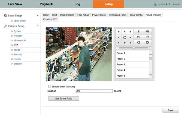
TABLE OF CONTENTS
4.2.9 Email . . . . . . . . . . . . . . . . . . . . . . . . . . . . . . . . . . . . . . . . . . . . . . . . . . . . . . . . . . . . . . . . . . . . . . . . . 33
4.2.10 NAT . . . . . . . . . . . . . . . . . . . . . . . . . . . . . . . . . . . . . . . . . . . . . . . . . . . . . . . . . . . . . . . . . . . . . . . . . . 35
4.3 Video/Audio menus. . . . . . . . . . . . . . . . . . . . . . . . . . . . . . . . . . . . . . . . . . . . . . . . . . . . . . . . . . . . . . . . . 35
4.3.1 Video . . . . . . . . . . . . . . . . . . . . . . . . . . . . . . . . . . . . . . . . . . . . . . . . . . . . . . . . . . . . . . . . . . . . . . . . . 35
4.3.2 ROI. . . . . . . . . . . . . . . . . . . . . . . . . . . . . . . . . . . . . . . . . . . . . . . . . . . . . . . . . . . . . . . . . . . . . . . . . . . 36
4.4 PTZ menus. . . . . . . . . . . . . . . . . . . . . . . . . . . . . . . . . . . . . . . . . . . . . . . . . . . . . . . . . . . . . . . . . . . . . . . . . 38
4.4.1 Basic menu. . . . . . . . . . . . . . . . . . . . . . . . . . . . . . . . . . . . . . . . . . . . . . . . . . . . . . . . . . . . . . . . . . . . 38
4.4.2 Limit menu. . . . . . . . . . . . . . . . . . . . . . . . . . . . . . . . . . . . . . . . . . . . . . . . . . . . . . . . . . . . . . . . . . . . 39
4.4.3 Initial Position menu. . . . . . . . . . . . . . . . . . . . . . . . . . . . . . . . . . . . . . . . . . . . . . . . . . . . . . . . . . . . 40
4.4.4 Park Action menu. . . . . . . . . . . . . . . . . . . . . . . . . . . . . . . . . . . . . . . . . . . . . . . . . . . . . . . . . . . . . . .41
4.4.5 Privacy Mask menu. . . . . . . . . . . . . . . . . . . . . . . . . . . . . . . . . . . . . . . . . . . . . . . . . . . . . . . . . . . . . 41
4.4.6 Scheduled Tasks menu . . . . . . . . . . . . . . . . . . . . . . . . . . . . . . . . . . . . . . . . . . . . . . . . . . . . . . . . . . 42
4.4.7 Clear Config menu. . . . . . . . . . . . . . . . . . . . . . . . . . . . . . . . . . . . . . . . . . . . . . . . . . . . . . . . . . . . . . 44
4.4.8 Smart Tracking menu . . . . . . . . . . . . . . . . . . . . . . . . . . . . . . . . . . . . . . . . . . . . . . . . . . . . . . . . . . . 45
4.4.9 Prioritize PTZ menu. . . . . . . . . . . . . . . . . . . . . . . . . . . . . . . . . . . . . . . . . . . . . . . . . . . . . . . . . . . . . 46
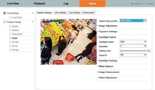
4.5 Image menus . . . . . . . . . . . . . . . . . . . . . . . . . . . . . . . . . . . . . . . . . . . . . . . . . . . . . . . . . . . . . . . . . . . . . . 47
4.5.1 Display Settings . . . . . . . . . . . . . . . . . . . . . . . . . . . . . . . . . . . . . . . . . . . . . . . . . . . . . . . . . . . . . . . . 47
4.5.2 OSD Settings. . . . . . . . . . . . . . . . . . . . . . . . . . . . . . . . . . . . . . . . . . . . . . . . . . . . . . . . . . . . . . . . . . . 49
4.5.3 Text Overlay . . . . . . . . . . . . . . . . . . . . . . . . . . . . . . . . . . . . . . . . . . . . . . . . . . . . . . . . . . . . . . . . . . . 49
4.5.4 Privacy Mask. . . . . . . . . . . . . . . . . . . . . . . . . . . . . . . . . . . . . . . . . . . . . . . . . . . . . . . . . . . . . . . . . . . 50
4.6 Security menus. . . . . . . . . . . . . . . . . . . . . . . . . . . . . . . . . . . . . . . . . . . . . . . . . . . . . . . . . . . . . . . . . . . . . 51
4.6.1 User . . . . . . . . . . . . . . . . . . . . . . . . . . . . . . . . . . . . . . . . . . . . . . . . . . . . . . . . . . . . . . . . . . . . . . . . . . 51
4.6.2 RTSP Authentication. . . . . . . . . . . . . . . . . . . . . . . . . . . . . . . . . . . . . . . . . . . . . . . . . . . . . . . . . . . . 53
4.6.3 Anonymous Visit . . . . . . . . . . . . . . . . . . . . . . . . . . . . . . . . . . . . . . . . . . . . . . . . . . . . . . . . . . . . . . . 53
4.6.4 IP Address Filter. . . . . . . . . . . . . . . . . . . . . . . . . . . . . . . . . . . . . . . . . . . . . . . . . . . . . . . . . . . . . . . . 54
4.7 Events menus . . . . . . . . . . . . . . . . . . . . . . . . . . . . . . . . . . . . . . . . . . . . . . . . . . . . . . . . . . . . . . . . . . . . . . 55
4.7.1 Motion Detection. . . . . . . . . . . . . . . . . . . . . . . . . . . . . . . . . . . . . . . . . . . . . . . . . . . . . . . . . . . . . . . 55
4.7.2 Video Tampering . . . . . . . . . . . . . . . . . . . . . . . . . . . . . . . . . . . . . . . . . . . . . . . . . . . . . . . . . . . . . . . 58
4.7.3 Alarm Input . . . . . . . . . . . . . . . . . . . . . . . . . . . . . . . . . . . . . . . . . . . . . . . . . . . . . . . . . . . . . . . . . . . 60
4.7.4 Alarm Output . . . . . . . . . . . . . . . . . . . . . . . . . . . . . . . . . . . . . . . . . . . . . . . . . . . . . . . . . . . . . . . . . . 62
4.7.5 Exception . . . . . . . . . . . . . . . . . . . . . . . . . . . . . . . . . . . . . . . . . . . . . . . . . . . . . . . . . . . . . . . . . . . . . 65
4.8 Storage menus . . . . . . . . . . . . . . . . . . . . . . . . . . . . . . . . . . . . . . . . . . . . . . . . . . . . . . . . . . . . . . . . . . . . . 66
4.8.1 Record Schedule. . . . . . . . . . . . . . . . . . . . . . . . . . . . . . . . . . . . . . . . . . . . . . . . . . . . . . . . . . . . . . . . 66
4.8.2 Storage Management. . . . . . . . . . . . . . . . . . . . . . . . . . . . . . . . . . . . . . . . . . . . . . . . . . . . . . . . . . . 68
4.8.3 NAS . . . . . . . . . . . . . . . . . . . . . . . . . . . . . . . . . . . . . . . . . . . . . . . . . . . . . . . . . . . . . . . . . . . . . . . . . . 69
4.8.4 Snapshot. . . . . . . . . . . . . . . . . . . . . . . . . . . . . . . . . . . . . . . . . . . . . . . . . . . . . . . . . . . . . . . . . . . . . . 71
ALIBI™ IP Camera Software User Manual v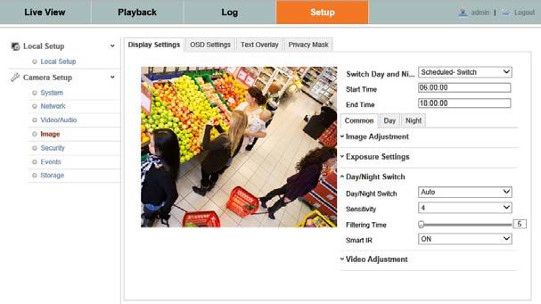
vi
SECTION 1: OVERVIEW

SECTION 1
Overview
Congratulations on purchasing your new ALIBI™ IP camera! Your camera includes the following key features:

General
•    Megapixel CMOS progressive scan sensor
•    High definition video streaming
•    Dual-stream video support
•    Video stream compression using H.264 standard.
•    3D-DNR noise reduction
•    Wide dynamic range (WDR)
•    Backlight compensation
•    IR sensors for night vision
•    Dual power capable - Power over Ethernet (PoE) or 12 Vdc
•    Weatherproof IP66 rated
•    Vandal proof
•    Mobile surveillance
•    PTZ functionality (ALI-IPZ models only)

1.1 Typical application configurations
Your Alibi IP can function well in many different network configurations. The most common configurations are:
•    Camera is installed on an IP network and managed by a Network Video Recorder (NVR)
•    Camera is installed on an IP network and uses a network based storage device, such as a NAS or SMB/CIFS server, to archive
     recorded video and screen captures. The camera is managed by a PC with an Internet browser.
•    Camera is installed on an IP network and connected directly by a PC with a Video Management System (VMS).

Since the Alibi camera is an IP based device, several other application configurations are also possible.

Important considerations
•    Alibi cameras do not contain internal storage for video recording. Therefore, storage for this data must be in an external device
     such as an Network video Recorder (NVR), a Network Attached Storage device (NAS or SMB/CIFS device), or a PC with a Video
     Management System (VMS) that stores recorded video.
•    Security devices on your network should be configured with static (fixed) IP addresses whenever possible. Using fixed IP
     addresses for these devices greatly simplifies the communication between the components of your security system.
•    Alibi cameras include a web interface that enables remote access to the camera through an Internet browser such as
     Microsoft® Internet Explorer®, Mozilla® Firefox®, Google Chrome™, and Apple® Safari®. With this interface, you can watch live
     video and perform all camera configuration functions. You can also play back recorded video, download recordings, perform
     screen captures, and other functions. This document uses the web interface to show all functions of the camera.

                                                                          ALIBI™ IP Camera Software User Manual                          i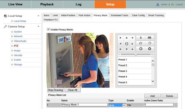
SECTION 1: OVERVIEW

1.1.1 Camera is managed by an NVR
The most typical application for the camera is to be installed with a compatible NVR. With the NVR, the camera can be installed
anywhere on a LAN that is accessible to the NVR. With the Alibi ALI-NVR30 Series NVRs, the camera can be either installed on the
LAN, or connected directly to the NVR’s built-in Ethernet switch and be configured automatically.

                                                 Router

                   Camera                        LAN                 LAN                       NVRr

1.1.2 Camera uses network device for video storage
Cameras that do not include internal data storage can be installed on an IP network and configured to store recorded video a
network based storage device, such as a Network Attached Storage (NAS) device, or a device using Server Message Block (SMB)
or Common Internet File System (CIFS) protocol. With this configuration, the camera is managed through a PC with an Internet
browser and access to the LAN where the camera is installed, and recorded video can be played back either through the camera, or
by direct access to the recorded video files on the storage device.

                                                       Router

                                                                              LAN

          Camera                           LAN

                                                                   LAN
                                                                                                               IE

                                                   NFS or
                                                 SMB/CIFS
                                                  Storage                                                  PC with browser

2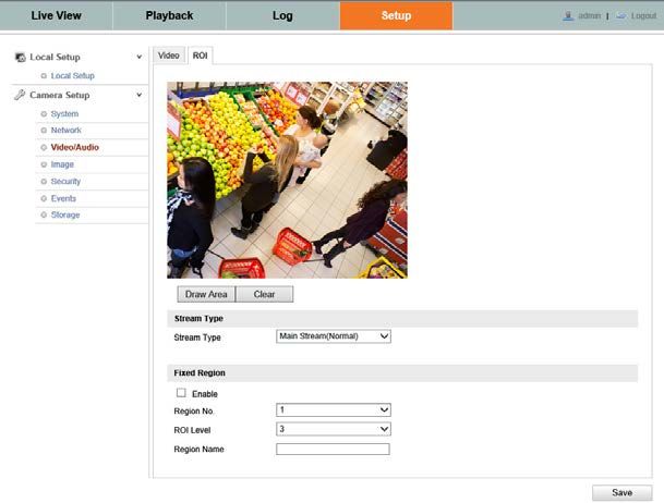
SECTION 1: OVERVIEW

1.1.3 Camera is managed by a VMS
Cameras installed on a network can be managed through a PC with Video Management System (VMS) software. In this
configuration, storage of recorded video usually occurs internally in the PC. VMS software is not provided with your camera.

                                                   Router

         Camera                            LAN                                 LAN                            VMS

                                                                                                        PC with VMS

1.2 PC requirements
The PC you use to connect to your camera with an Internet browser should meet the following requirements:
•    Operating System: Microsoft® Windows® XP SP1 and above, Windows Vista, 7, Server 2003, Server 2008 (32 bit)
•    CPU: Intel® Pentium® IV 3.0 GHz or faster
•    RAM: 1GB or more
•    Display: 1024 × 768 resolution or higher
•    Internet Browser: Microsoft® Internet Explorer® 7 and newer, Apple® Safari® 5.02 and newer, Mozilla® Firefox 3.5 and
     newer, Google Chrome™ 8 and newer

                                                                       ALIBI™ IP Camera Software User Manual                   3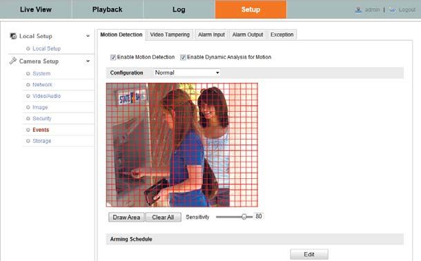
SECTION 2: NETWORK CONNECTIONS

SECTION 2
Network Connection
Alibi cameras use a standard RJ45 10/100BASE-T Ethernet interface to communicate with other devices. The Ethernet interface also
supports Power over Ethernet (PoE). Whenever possible, configure the components of your security equipment on the LAN with
static (fixed) IP addresses.

Cameras should be installed on the same Ethernet subnetwork (subnet) that contains the NVR or PC with VMS used to manage
them, or contains a network storage device for saving recordings.

2.1 Locating cameras on the network - using Alibi Discover
The Alibi Discover Tool is used to “discover” Alibi cameras and NVRs/DVRs installed on the LAN and change their network settings.
The tool is provided on the software CD with your camera.

To use the tool:

1. Insert the software CD provided with your camera into an optical drive on the Microsoft Windows computer you will use to
   access your camera on the LAN.

2. On the CD, find the folder that contains the Alibi Discover Tool.

3. Copy the files in the folder to a new directory on your computer. The files should appear as shown in the directory shown
   below.

4. To open the Alibi Discover Tool, double click the file Alibi Discover Tool.exe. The tool will automatically discover Alibi
   cameras and recorders installed on the network.

     In the screen shown above, an ALI-IPV3030R camera was discovered. This camera, although installed on a subnet other than
     the one implied by its IP address is shown, is still found by the tool.

4
SECTION 2: NETWORK CONNECTIONS
5. To change the network settings of the camera to be compatible with the subnet where it is installed, do the following:
a. Click the device to highlight it. Notice that the network parameters are populated in the frame on the right.
ALIBI™ IP Camera Software User Manual 5SECTION 2: NETWORK CONNECTION
b. Modify the network settings to values compatible with the subnet where it is installed.
c. Enter the admin password for the device in the password field. By default, the admin user password for Alibi cameras
is 1111.
d. Click the Save button. The new IP address, port, etc. settings will appear in the list with the device you modified.
6. Close the Alibi Discover Tool by clicking the Close icon ( T ) in the upper-right corner of the screen.
2.1.1 Restore Default Password
The Alibi Discover Tool includes a feature in the lower right corner of the screen labeled Restore Default Password. This feature
is a Support-only tool that allows them to reset the password if it was changed and lost. At this time, it is only used for Alibi dome-
style cameras, and Alibi NVRs and DVRs. If you lost the password for any of these devices, contact your Support organization for
assistance.
If you are using an Alibi bullet-style camera, you can reset the camera to its default configuration (including the password) by
pressing the RESET button on the back of the camera.
6SECTION 3: REMOTE ACCESS
SECTION 3
Remote Access
When is connected to a local network (LAN), you can access it from another computer on the LAN through Microsoft® Internet
Explorer®. If using IE 10 or higher, you must configure it for “Compatibility” mode for the IP address you are logging into.
When connecting to an Alibi camera, you must enter a User Name and Password. Note that some user permissions disallow features
remote access to the camera.
When logging into the camera from a remote computer for the first time, you must install a plug-in program named
WebComponents. The procedure for installing the program using Internet Explorer 11 is shown below. Subsequent log ins do not
require you to reinstall WebComponents.
3.1 Remote login
To access the camera from a computer on the LAN:
1. Open the Microsoft Internet Explorer browser on your compute and enter the IP address of the camera in the URL field. In the
example below, the IP address of the camera is 192.168.75.76.
ALIBI™ IP Camera Software User Manual 7SECTION 3: REMOTE ACCESS
2. In the login window, enter your User Name and Password in the appropriate fields, then click Login. The default User
Name and Password for Alibi cameras is admin and 1111.
3. If this is the first time you are logging into a camera at this IP address AND you are using Internet Explorer 10 or newer, you
must configure it for Compatibility mode:
a. In Internet Explorer, click the Tools icon (located to the right of the tabs), then select Compatibility View settings from the
drop-down menu.
Tools icon
b. In the Compatibility View Settings window, ensure that the IP address of your camera is in the Add this website field,
then click Add.
8SECTION 3: REMOTE ACCESS
c. After clicking Add, the IP address will appear in the Websites list. Click Close.
4. If this login is the first login to an Alibi camera from your computer and browser, continue with the following sub-steps to
install WebComponents:
a. After a successful login to the NVR, a message will appear in the middle of the Live View window requiring you to load a
plug-in. Click on the message to continue, then click Run in the message box at the bottom of the screen.
ALIBI™ IP Camera Software User Manual 9Some computer security software may attempt to block you from running WebComponents.exe. If necessary, open the Internet
Explorer downloads list, right click on the WebComponents.exe file name, then click Run Anyway.
NOTE
b. In the Setup - WebComponents window opens, click Next to continue.
Installing the WebComponents plugin may require that you close the browser. Follow the on-screen instructions, then
restart your browser after the installation is finished.
c. Allow the plug-in installation to complete. When the following window appears, click Finish.
10SECTION 3: REMOTE ACCESS
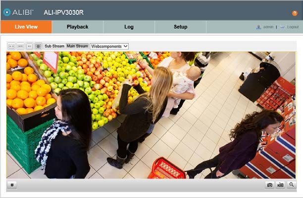
3.2 Remote Live View screen
After logging into the camera, the Live View - Main stream window initially appears. In this screen, you can:
• Change the viewing options. Click the appropriate button to select a 4:3 or 16:9 aspect ratio, full size (X1 button), and Sub
Stream or Main Stream.
Live View options Screen select tabs Live View image Logout button
Capture, Record, Enable e-PTZ icons
• Live view displays for PTZ cameras have additional controls. A PTZ control panel can be opened and closed by clicking the PTZ
panel button.
ALIBI™ IP Camera Software User Manual 11SECTION 3: REMOTE ACCESS
PTZ control panel PTZ panel open/close
—— For cameras with PTZ capability, click the PTZ control panel button to open the frame shown above on the right.
—— Each PTZ camera can be configured to include up to 128 “Presets”, each of which can be quickly set and called. Presets are
used to quickly reposition the camera for specific views (pan, tilt, zoom, focus). The list of Presets is presented beneath
the control panel on the right side of the screen.
12SECTION 3: REMOTE ACCESS
• Capture the screen or start and stop recording. Captures and recordings are saved on the local HDD as configured in Local
Setup menu.
• Switch from window mode to full screen mode by double clicking anywhere in the Live View video window. To return to
window mode, double click anywhere.
• For cameras with Audio capability, select Mute and adjust the audio volume.
3.3 Playback screen
Open the Playback screen by clicking the Playback tab. The Playback screen allows you to review video recorded from one camera
or several cameras concurrently. Also, video can be downloaded to your local computer.
Start/Stop Clipping
Download
Capture Recording
Play motion controls Audio play / mute Zoom Images
Timeline (drag to reposition) Playback timestamp Record legend Expand / contract timeline
ALIBI™ IP Camera Software User Manual 13SECTION 3: REMOTE ACCESS
To playback recorded video:
• Click the day on the calendar when the video was recorded. In the example above, February 5, 2014 was selected.
• Click the Search button. Recorded video is indicated by a colored band on the timeline. The color legend is shown below the
timeline. You can expand or contract the timeline with the icons on the right.
• At the bottom of the screen, drag the timeline left or right to position the video clip you want to play at the yellow Playback
timestamp line.
• In the play controls, click the Play button ( u )to begin playing video. When the video is playing, the Play button changes to
a Pause button ( ; ).
• Use the Audio play / mute controls to adjust the audio level (audio capable cameras only).
To save a portion of recorded video
• While playing back video, advance the playback to the beginning of the portion of the video you want to save.
• Click the Start / Stop clipping icon (black scissors) . The icon will change to a Stop clipping icon (red scissors).
• When the playback the end of the portion you want to save, clip the Stop clipping icon.
• Playback the video clip you saved. The clip is saved to the location on your local HDD specified in the Setup (tab) | Local
Setup menu. See “3.5.1 Local Setup menu” on page 17 for more information.
To download a video recording
• In the Playback screen, Click the Download recording icon.
• In the options on the right panel, select the type of recording you want to download, the Start Time and the End Time when
the recording was made.
• Click the Search button. A list of video recordings meeting the search criterion is shown in the window. NOTE: Video
recordings that are larger than the Record File Size selected on the Setup (tab) | Local Setup menu (see “3.5.1 Local Setup
menu” on page 17) appear in the list as multiple video segments.
14SECTION 3: REMOTE ACCESS
• Check the box(es) for the video recording(s) you want to download, then click the Download button. The progress of the
download(s) is indicated in the column on the right.
• Playback the video recording you downloaded. The recording is saved to the location on your local HDD specified in the Setup
(tab) | Local Setup menu. See “3.5.1 Local Setup menu” on page 17 for more information.
To download images
• In the Playback screen, Click the Download images icon.
• In the options on the right panel, select the type of images you want to download, the Start Time and the End Time when
the recording was made.
• Click the Search button. A list of video images meeting the search criterion is shown in the window.
• Check the box(es) for the image(s) you want to download, then click the Download button. The progress of the download(s)
is indicated in the column on the right.
ALIBI™ IP Camera Software User Manual 15SECTION 3: REMOTE ACCESS
• Open the image(s) you downloaded. The image(s) is saved to the location on your local HDD specified in the
Setup (tab) | Local Setup menu. See “3.5.1 Local Setup menu” on page 17 for more information.
3.4 Remote Log screen
Open the Log screen by clicking Log in the screen header. The camera log report is created by specifying a search criteria using the
menu in the right frame (or using the default options), then clicking the Search button. The search criteria menu includes filters to
search for Major and Minor type events, and specify the start and end time of the report.
16SECTION 3: REMOTE ACCESS:
Log reports can be saved in either text or Excel formats by clicking the Save Log icon.
3.5 Remote SETUP screen
Open the Configuration screen by clicking the Configuration tab. The Configuration menus are organized in two sections: one for
Local Setup, and one for Camera Setup. The Local Setup section defines the Live View Parameters, Record File (local PC) Settings,
and Picture and Clip Settings. Camera Setup includes all configurable features of the camera, including the System, Network,
Storage locations, etc. Users who log into the camera through the remote connection may or may not be allowed to view or change
the configuration of the local settings or camera, depending on the permissions granted to their user name by admin user.
3.5.1 Local Setup menu
The local configuration includes parameters of Live View, Record Files (local PC settings), and Picture and Clip Settings. The record
files and captured pictures are created using your web browser and saved on the PC running the browser.
To open the Local Setup screen, go to Setup tab | Local Setup.
Configuration settings are defined below:
Live View Parameters: Set the protocol type and live view performance.
• Protocol Type: Select either TCP, UDP, MULTICAST or HTTP.
—— TCP: Ensures complete delivery of streaming data and better video quality. Real-time transmission is affected.
—— UDP: Provides real-time audio and video streams.
—— HTTP: Allows the same quality as of TCP without setting specific ports for streaming under some network environments.
ALIBI™ IP Camera Software User Manual 17—— MULTICAST: See TCP/IP settings for more information.
• Live View Performance: Set the live view performance to Shortest Delay, Real Time, Balanced or Best Fluency.
• Rules: Reserved for future use.
• Image Format: Select the file format for captured images (JPEG or BMP).
Record File Settings: Set the saving path of the recorded video files. Valid for the record files you recorded with the web browser.
• Record File Size: Select the segment size of the manually recorded and downloaded video files. Options are 256MB, 512MB
or 1GB.
• Save record files to: Set the saving path for the manually recorded video files.
• Save downloaded files to: Set the saving path for the downloaded video files in playback mode.
Picture and Clip Settings: Set the saving paths on your PC of the captured pictures and clipped video files with the web browser.
• Save snapshots in live view to: Set the saving path of the manually captured pictures in Live View mode.
• Save snapshots when playback to: Set the saving path of the captured pictures in playback mode.
• Save clips to: Set the saving path of the clipped video files in playback mode.
3.5.2 Camera Setup menus
Camera Setup menus are described in “SECTION 4 Camera Setup Menus” on page 19.
18SECTION 4: CAMERA SETUP MENUS
SECTION 4
Camera Setup Menus
Camera Setup menus that appear when accessing Alibi cameras through a web browser present the complete set of configuration
options. These options are organized in a tree of menus as shown below.
Camera Setup
System
Device Time Maintenance DST Service
Information Settings
Network
TCP/IP Port DDNS SNMP 802.1X
Qos FTP UPnP™ Email NAT
Video/Audio
Video ROI
PTZ*
Basic Limit Initial Position Park Position Privacy Mask
Scheduled Clear Config Smart Tracking Prioritize
Tasks PTZ
Image
Display OSD Text Privacy
Settings Settings Overlay Mask
Security
User RSTP Anonymous IP Address
Authentication Visit Filter
Events
Motion Video Alarm Alarm Exception
Detection Tampering Input Output
Storage
Record Storage NAS Snapshot
Schedule Management
ALIBI™ IP Camera Software User Manual 19SECTION 4: CAMERA SETUP MENUS
NOTE * The PTZ submenu appears only in cameras with PTZ capabilities, such as the ALI-IPZ5030 series cameras.
4.1 System Setup menus
4.1.1 Device Information
The Device Information screen shows the basic information for the device, including the Device Name and Device No. (number),
model, serial number, software versions, and other features. To open the Device Information screen, go to
Setup tab | System | Device Information
In the Device information screen, you can change the Device Name and number by editing the fields, then clicking Save.
4.1.2 Time Settings
Use the Time Settings screen to set the correct time and date in the camera. Because video recordings and captures are time
stamped with this information, the correct date and time is important if the files become evidence of some event. To open the Time
Settings menu, go to Setup tab | System | Time Settings
20SECTION 4: CAMERA SETUP MENUS
• Select the Time Zone from the drop-down menu. In some system applications, the monitoring system (NVR, VMS) may be in
a different time zone from the camera. Select the time zone that best supports your system objectives.
Time Sync.
You can synchronize the clock in your camera either from an NTP server, by setting it manually, or synchronizing it with your
computer.
• NTP: Synchronizing Time by NTP Server.
a. Check the checkbox to enable the NTP function.
b. Configure the following settings:
Server Address: IP address of NTP server.
NTP Port: Port of NTP server.
Interval: The time interval between the two synchronizing actions with NTP server.
If the camera is connected to a public network, use a NTP server that has a time synchronization function, such as the server at the
NOTE National Time Center (IP address: 210.72.145.44). If the camera is set in an isolated network, NTP software can be used to establish
a NTP server for time synchronization.
• Manual Time Sync.: Set the camera clock manually or synchronize the clock in your PC.
a. Check the checkbox to enable the NTP function.
b. Do one of the following:
ALIBI™ IP Camera Software User Manual 21SECTION 4: CAMERA SETUP MENUS
* Enter the preferred time in the Set Time field, then click Save.
* Check the Sync. with computer time box, then click Save.
NOTE After setting the time in the camera, open the DST tab to setup the Daylight Savings Time configuration for the camera.
4.1.3 Maintenance
The Maintenance screen includes the camera-related maintenance functions. To open the Maintenance screen, go to
Setup tab | System | Maintenance
Reboot
Click Reboot to restart the camera. When you reboot the camera, now configuration parameters are changed.
Restore
Click Restore to reset all configuration parameters, except the IP network settings and user information, to their factory default
values.
22SECTION 4: CAMERA SETUP MENUS
Default
Click Default to reset all configuration parameters, INCLUDING the IP network settings and user information, to their factory
default values. The network IP address is reset to 192.0.0.64.
Export
Click Export to save the camera configuration file for Import later if necessary. You can also export the configuration and use it to
quickly configure other cameras using the Import feature.
Import Config. File
Click Browse to locate a previously saved camera configuration file to import, then click Import. The import status is shown on
the line below.
Remote Upgrade (Firmware)
NOTE Firmware upgrade should ONLY be performed if recommended by your Support organization.
You can upgrade in the camera either by browsing to the directory where the firmware upgrade file exists, or specifying the full
path to the upgrade file. To upgrade firmware:
1. In the Remote Upgrade section of the Maintenance screen, click the drop-down list, then select either Firmware or
Firmware Directory. In the example below, Firmware was selected.
ALIBI™ IP Camera Software User Manual 232. Click Browse, then browse to the firmware file (for Firmware) or the directory where the firmware file exists (for Firmware Directory). 3. Click Upgrade. 4. Wait until the upgrade process completes. (1 ~ 10 minutes), then log into your camera. (You can use the camera again when the upgrade finishes.) 5. Power off the camera. 6. Power on the camera again, then open the Device Information screen. Go to Setup tab | System | Device Information 7. Verify that the screen shows the new Firmware Version is installed. 4.1.4 DST (Daylight Savings Time) Use the DST menu to configure the Daylight Savings Time mode for the camera. To setup the camera automatically adjust the clock for DST: 1. Open Time Settings interface: Go to Setup tab | System | DST 2. Check the DST box, then set the Start Time and End Time using the options in the drop down lists. 3. Click Save. 4.1.5 Service The Service menu allows you enable or disable the IR light and Telnet. Depending on the camera model, other options may be present. To open the Service menu, go to Setup tab | System | Service 24
SECTION 4: CAMERA SETUP MENUS

In the the Service menu, check or uncheck the boxes for the items you want to enable or disable, then click Save.

4.2 Network menus

4.2.1 TCP/IP
TCP/IP settings must be properly configured before you operate the camera over network. The camera supports both the IPv4
and IPv6. Both versions may be configured simultaneously without conflicting to each other, and at least one IP version should be
configured.

Steps:
1. Open TCP/IP settings interface: Go to Setup tab | Network | TCP/IP

                                                                       ALIBI™ IP Camera Software User Manual                    25
SECTION 4: CAMERA SETUP MENUS
2. Configure the basic network settings, including the NIC Type, IPv4 or IPv6 Address, IPv4 or IPv6 Subnet Mask, IPv4 or IPv6
Default Gateway, MTU settings and Multicast Address.
Notes
• The valid value range of MTU is 500 ~ 1500.
• Multicast sends a stream to the multicast group address and allows multiple clients to acquire the stream simultaneously by
requesting a copy from the multicast group address. Before using this function, you must enable the Multicast function of your
router.
3. Click Save. The camera must reboot for new settings to take effect.
4.2.2 Port
You can change the HTTP, RTSP HTTPS and Server port numbers the camera will use. To change any of these settings:
1. Open Network Port settings interface: Go to Setup tab | Network | Port
26SECTION 4: CAMERA SETUP MENUS
2. Edit the HTTP, RTSP HTTPS and/or Server port numbers you want to change.
—— HTTP Port: The default port number is 80, and can be changed to any port range 1024 to 65535.
—— RTSP Port: The default port number is 554.
—— HTTPS Port: The default port number is 443, and can be changed to any port range 1024 to 65535.
—— Server Port: The default server port number is 8000.
3. Click Save. The camera must reboot for new settings to take effect.
4.2.3 DDNS
Registration on the DDNS server is required before configuring the DDNS settings of the camera.
Steps
1. Open Network DDNS settings interface: Go to Setup tab | Network | DDNS
ALIBI™ IP Camera Software User Manual 27SECTION 4: CAMERA SETUP MENUS
2. Check the Enable DDNS checkbox to enable this feature (see above).
3. Select one of the DDNS Type. Options are DynDNS, IPServer, and NO-IP.
—— For IPServer, you must configure the camera with a static IP address, subnet mask, gateway and preferred DNS. These
values can be obtained from your Internet Service Provider (ISP).
i. In the Server Address field, enter static IP address of the computer that runs the IP Server software.
ii. Click Save.
—— For DynDNS:
i. Enter Server Address of DynDNS (e.g. members.dyndns.org).
ii. In the Domain text field, enter the domain name obtained from the DynDNS website.
iii. Enter the User Name and Password registered on the DynDNS website.
iv. Click Save.
—— For NO-IP:
28SECTION 4: CAMERA SETUP MENUS
i. Enter Server Address field with the Server Address.
ii. In the Domain text field, enter the domain name obtained from the NO-IP website.
iii. Enter the User Name and Password registered on the NO-IP website.
iv. Click Save.
4.2.4 SNMP
You can set the SNMP function to acquire camera status, parameters and alarm information and manage the camera remotely when
it is connected to the network.
Before setting the SNMP, please download the SNMP software and manage to receive the camera information via SNMP port. By
setting the Trap Address, the camera can send the alarm event and exception messages to the surveillance center.
Note: The SNMP version you select should be the same as that of the SNMP software. And you also need to use the different version
according to the security level you required. SNMP v1 provides no security and SNMP v2 requires password for access. SNMP v3
provides encryption. When using SNMP v3, HTTPS protocol must be enabled.
ALIBI™ IP Camera Software User Manual 29SECTION 4: CAMERA SETUP MENUS 4.2.5 802.1X IEEE 802.1X is an IEEE Standard for Port-based Network Access Control (PNAC). It is part of the IEEE 802.1 group of networking protocols. It provides an authentication mechanism to devices wishing to attach to a LAN or WLAN. The 802.1X mechanism requires an authenticator (authentication device), and typically an authentication server. The authenticator is a network device, such as an Ethernet switch or wireless access point; and the authentication server is typically a host running software supporting the RADIUS and EAP protocols. The authentication server must be configured to verify the credentials (user name and password) from the camera. 1. Open Network 802.1X settings interface: Go to Setup tab | Network | 802.1X 30
SECTION 4: CAMERA SETUP MENUS

1. Check the Enable IEEE 802.1X box to enable the feature.

2. Configure the 802.1X settings, including EAPOL version, user name and password. The EAPOL version must be identical with
   that of the router or the switch.

3. Enter the user name and password to access the server.

4. Click Save. A reboot is required for these settings to be in effect.

4.2.6 QoS
QoS (Quality of Service) can help solve network delay and network congestion problems by configuring the priority of sent data. To
open the QoS screen, go to Setup tab | Network | QoS

To configure QoS:

1. Edit the DSCP fields for Video/Audio DSCP, Event/Alarm DSCP and Management DSCP. The valid value range of the
   DSCP is 0-63. Larger DSCP values have higher priority.

   NOTE         DSCP refers to the Differentiated Service Code Point. The DSCP value is used in the IP header to indicate the priority of the data.

                                                                                  ALIBI™ IP Camera Software User Manual                               31
SECTION 4: CAMERA SETUP MENUS
2. Click Save. The settings are applied when the camera is rebooted.
4.2.7 FTP
The FTP feature can be used to upload captured pictures to an FTP server. Picture captures can be triggered by events or a timing
snapshot. To open the FTP screen, go to Setup tab | Network | FTP
1. To use FTP, enter the following parameters:
—— FTP Server Address: Enter the IP address of the FTP server you want to use.
—— FTP server Port number. The default value of the FTP port is 21.
—— User Name: User name you use to authenticate access to the server.
—— Password and Confirm: Enter both fields with the password of the User Name.
—— Directory Structure: In the Directory Structure field, select the root directory, parent directory or child directory. When
the parent directory is selected, you have the option to use the Device Name, Device Number or Device IP for the name of
the directory; and when the Child Directory is selected, you can use the Camera Name or Camera No. as the name of the
directory.
—— Upload Type: To enable uploading the captured picture to the FTP server.
—— Anonymous: Check the Anonymous box to enable the anonymous access to the FTP server. Use this option when access
to the FTP Server does not require a User Name and Password. The anonymous access function must be supported by the
FTP server.
2. Click Save.
To upload the captured pictures to FTP server, you must enable continuous snapshot or event-triggered snapshot on Snapshot
NOTE
screen.
To upload the captured pictures to FTP server, you must select Enable Timing Snapshot or Event -Triggered Snapshot on the
Setup (tab) | Storage | Snapshot screen.
32SECTION 4: CAMERA SETUP MENUS
4.2.8 UPnP™
Universal Plug and Play (UPnP™) is a networking architecture that provides compatibility among networking equipment, software
and other hardware devices. The UPnP protocol allows devices to connect seamlessly and to simplify the implementation of
networks in the home and corporate environments.
With the function enabled, you don’t need to configure the port mapping for each port, and the camera is connected to the Wide
Area Network via the router. To open the UPnP screen, go to Setup tab | Network | UPnP™
Check the Enable UPnP™ box to use this feature, edit the Friendly Name field if necessary, then click Save to retain your settings.
You can verify UPnP™ functionality by opening a file browser, then looking at the items listed in the Network directory.
4.2.9 Email
The Email feature is used to send an email message to up to three email address when specific events occur within the camera. The
Email menu is used to configure the sender’s email server, user name and password, and the receiver(s) email address(es). Events
that activate email alerts are configured in other menus.
The camera must be configured for Internet access to connect to your email server. Configure TCP/IP settings before configuring
your email preferences.
To open the Email menu, go to Setup tab | Network | Email
ALIBI™ IP Camera Software User Manual 33SECTION 4: CAMERA SETUP MENUS
1. Configure the following settings:
—— Sender: The name of the email sender.
—— Sender’s Address: The email address of the sender.
—— SMTP Server: The SMTP Server IP address or host name (e.g., smtp.263xmail.com).
—— SMTP Port: The SMTP port. The default TCP/IP port for SMTP is 25 (not secured). The the SSL SMTP port is 465.
—— Enable SSL: Check the checkbox to enable SSL if it is required by the SMTP server.
—— Attached Image: Check this box if you want to send email with an image.
—— Interval: The interval is the time between two emails sent wiht attached pictures.
—— Authentication (optional): If your email server requires authentication, check this box to use authentication to connect
to this server. You must specify your email User Name and Password.
—— Choose Receiver: Select the receiver to which the email is sent. Up to 3 receivers can be configured.
—— Receiver: The name of the user to be notified.
—— Receiver’s Address: The email address of user to be notified.
2. Click Save.
34SECTION 4: CAMERA SETUP MENUS
4.2.10 NAT
The NAT menu enables you to specify the external port and IP address for HTTP, RTSP and a server port. You can enable port
mapping in either Auto or Manual modes. This feature is disabled in Alibi cameras for corporate network security concerns.
4.3 Video/Audio menus
4.3.1 Video
The Video menu is used to setup the Main Stream video transmission settings, and Sub Stream settings for dual stream cameras. In
this example, the camera has two streams: Main Stream (Normal) and Sub Stream. The configuration parameters for both are
the same, but the capabilities of the two streams are much different.
To open the Video menu, go to Setup tab | Video/Audio | Video
ALIBI™ IP Camera Software User Manual 35SECTION 4: CAMERA SETUP MENUS
1. Select the Stream Type of the camera you want to configure. Main Stream is usually for recording and live viewing with
good bandwidth, and Sub Stream should be used for live viewing when the bandwidth is limited.
2. Configure the following settings for your preferred performance:
—— V ideo Type: Select the stream type to video stream or video and audio composite stream (for cameras with audio
capability). For cameras with audio, the audio signal is recorded only when the Video Type is Video & Audio.
—— Resolution: Select the resolution of the video output.
—— Bitrate Type: Select either Constant or Variable.
—— Video Quality: When bitrate type is selected as Variable, you can select one of six levels of video quality. Higher video
quality requires more network bandwidth.
—— Frame Rate: Set the frame rate to 1/16 ~ 25 fps. The frame rate is the rate at which video frames the are sent to the
receiving device, or the rate at which the video stream is recorded. A higher frame rate produces a smother image with
higher quality throughout, but requires more network bandwidth.
—— Max. Bitrate: Set the maximum bitrate to 32 ~ 16384 Kbps. The higher value corresponds to the higher video quality at
a cost of higher network bandwidth.
—— Video Encoding: When the Stream Type of the camera is Main Stream, the Video Encoding standard can be set to
H.264. When the Stream Type of the camera is Sub Stream, the Video Encoding standard can be set to H.264 or MJPEG.
—— Profile: The profile for this camera is Main Profile. No other profiles are selectable.
—— I Frame Interval: Set the I-Frame interval to 1~400. The I-frame interval represents the rate at which the entire video
frame is transmitted (refreshed) when using a video compression technology such as H.264.
—— SVC: Scalable video coding is an extension of the H.264/AVC standard. The technology encodes the video signal with
layers; the basic layer and several enhanced layers and it is adaptive to the network condition to transfer different video
streams. For example, when the bandwidth is limited, only the basic layer data is encoded and transferred. You can
enable the function when you want to see the video with several terminals, such as the mobile phone with 3G network,
or the personal computer with IP network.
4.3.2 ROI
ROI (Region of Interest) encoding allows you to identify the important areas of the image and apply more compression resources
to improve the quality of that area instead of the lesser important background. The ROI area may appear more focused, while the
background area is less focused. The ROI feature is available on only some cameras.
There are two types of ROI encoding:
• Fixed Region: Fixed region encoding is the ROI encoding for a manually configured area. And you can choose the Image
Quality Enhancing level for ROI encoding, and you can also name the ROI area.
• Dynamic Tracking (not Fixed Region): Dynamic tracking refers to the ROI defined by intelligent analysis such as human face
detection. You can choose the Image Quality Enhancing level for the ROI encoding.
To open the ROI menu, go to Setup tab | Video/Audio | ROI
36SECTION 4: CAMERA SETUP MENUS
To define the ROIs:
1. Click the Draw Area button.
2. Using your mouse, drag a rectangle over the region of interest on the image.
3. Click the Stop Drawing button.
4. Choose the stream type to set the ROI encoding (Main Stream or Sub Stream).
5. Choose the ROI type. Check the Fixed Region box for Fixed Region encoding. Clear the box for Dynamic Tracking.
—— If you enabled Fixed Region, you can also select the Region number (1 .. 3), the ROI Level (Image Quality Enhancing
level) and enter a Region Name.
—— If Fixed Region is not enabled (i.e. Dynamic Tracking), select the the ROI Level (Image Quality Enhancing level).
6. Click Save.
7. Repeat the steps above to define additional regions. You can define up to three ROI regions.
ALIBI™ IP Camera Software User Manual 37SECTION 4: CAMERA SETUP MENUS
4.4 PTZ menus
PTZ sub-menus appear in the Settings display only when connecting to a PTZ capable camera.
4.4.1 Basic menu
Use the Basic menu to configure proportional pan, preset freezing, preset speed, and other elementary camera functions.
To open the Basic menu, go to Setup tab | PTZ | Basic
1. Configure the following settings:
Basic Parameters: Enable/disable proportional pan and preset freezing, set the preset speed, keyboard control speed, and
auto scan speed.
—— Proportional Pan: Enabling this function causes the pan/tilt speeds to change according to the amount of zoom. When
using high zoom, the pan/tilt speed slows to keeping the image from moving too fast on the Live View image display.
—— Preset Freezing: This function enables the Live View to switch from one scene defined by a preset to another, without
showing the middle areas between these two to ensure the surveillance efficiency. It can also reduce bandwidth usage.
Note: Preset freezing function is not in effect when calling a pattern.
—— Preset Speed: You can set the speed of a defined preset from 1 to 8.
—— Keyboard Control Speed: Define the speed of PTZ control by a keyboard as Low, Normal or High.
—— Auto Scan Speed: The dome provides 5 scan modes: auto scan, tilt scan, frame scan, random scan and panorama scan.
The scan speed can be set from level 1 to 40.
PTZ OSD: Set the on-screen PTZ status display duration.
38SECTION 4: CAMERA SETUP MENUS
—— Zoom Status: Set the OSD zooming status duration to 2 seconds, 5 seconds, 10 seconds, Always Close or Always Open.
—— PT Status: Set the azimuth angle display duration while panning and tilting to 2 seconds, 5 seconds, 10 seconds, Always
Close or Always Open.
—— Preset Status: Set the preset name display duration while calling the preset as 2 seconds, 5 seconds, 10 seconds,
Always Close or Always Open.
Power-off Memory: When the camera restarts after a power off, it can resume the previous PTZ status or actions it was
performing a specified time period before the power-off. You can set it to resume the status or actions it was performing 30
seconds, 60 seconds, 300 seconds or 600 seconds before power-off.
2. Click Save to save your settings.
4.4.2 Limit menu
The camera can be configured to only move only within limits of motion left, right, up, and down.
To open the Limit menu, go to Setup tab | PTZ | Limit
1. Click the checkbox of Enable Limit, then choose the limit type as Manual Stops or Scan Stops.
—— Manual Stops: When manual limit stops are set, you can operate the PTZ control panel manually only in the limited
surveillance area.
—— Scan Stops: When scan limit stops are set, the random scan, frame scan, auto scan, tilt scan, and panorama scan is
performed only within the limited surveillance area.
ALIBI™ IP Camera Software User Manual 39SECTION 4: CAMERA SETUP MENUS
Set the Manual Stops limits before setting Scan Stops limits. When you set these two limit types at the same time, Manual Stops is
NOTE
valid and Scan Stops is invalid.
2. Click the PTZ control buttons to determine the left/right/up/down limit stops; you can also call the defined presets and set
them as the limits of the dome.
3. Click Set to save the limit stops, or click Clear to clear the limit stops.
4.4.3 Initial Position menu
The initial position is the origin of PTZ coordinates. It can be the factory default initial position, or you can customize the initial
position according to your needs. To customize the position, use the procedure below.
To open the Initial Position menu, go to Setup tab | PTZ | Initial Position
1. Click the PTZ control buttons to point the camera at the initial target after startup. You can also call a predefined Preset
position and set the Initial Position to that target.
2. Do one of the following:
—— Click Set to save the position.
—— Click Clear to set the initial position to the factory default.
—— Click Goto to point the camera at the current Initial Position.
40SECTION 4: CAMERA SETUP MENUS
4.4.4 Park Action menu
The Park Action feature configures the camera to start a perform a predefined park action (scan, preset, pattern, etc.) automatically
after a period of inactivity (park time).
To open the Park Action menu, go to Setup tab | PTZ | Park Action
1. Check the box to Enable Park Action.
2. Set the Park Time. Park Time is the length in seconds of inactivity of the camera before it begins park actions.
3. Open the Action Type drop down list, then click to select the action you want to perform.
4. Click Save to save your settings.
4.4.5 Privacy Mask menu
Privacy mask allow you to cover selected areas on the Live View image to prevent them from being live viewed and recorded.
To open the Privacy Mask menu, go to Setup tab | PTZ | Privacy Mask
ALIBI™ IP Camera Software User Manual 41SECTION 4: CAMERA SETUP MENUS
Masked area over ATM keypad
1. Use the PTZ control buttons to display the area you want to cover with a privacy mask.
2. Click Draw Area, then click and drag the mouse across the area of the live video you want to mask. A semi-transparent box
with red squares on each corner will appear on the screen.
3. Drag the red corner squares as needed to form a polygon over the area you want to cover.
4. Click Stop Drawing to complete the drawing. You can also click Clear All to clear the areas you setup without saving them.
5. Click Add to save the privacy mask. The mask will be listed in the at the bottom of the menu. In the list, you can name the
mask, select a mask color, and enter an active zoom ratio.
6. Check the Enable Privacy Masks box to enable this function. The semi-transparent polygon will become opaque.
7. To change the shape or position, or delete the mask you created, click the mask entry in the list. A red border with red squares
in each corner will appear in the around the mask you picked. Drag the corners to change the shape, or click Delete to remove
the mask.
8. Repeat this procedure outlined above to configure additional privacy masks on the live video image. You can configure up to 24
privacy masks on the same image.
4.4.6 Scheduled Tasks menu
You can configure the camera to automatically perform certain different actions during different time periods.
42You can also read