Hook Reveal Series Operator Manual - ENGLISH - www.lowrance.com
←
→
Page content transcription
If your browser does not render page correctly, please read the page content below
Hook Reveal Series
Operator Manual

ENGLISH

            www.lowrance.com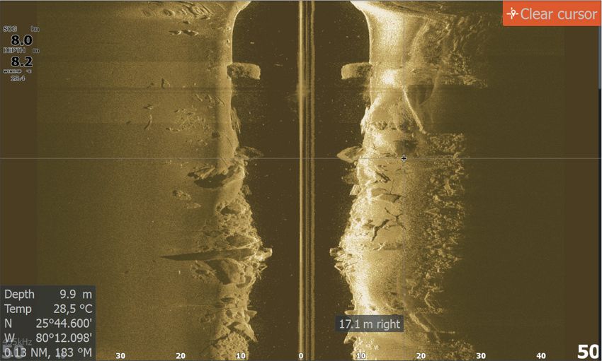
Preface

Disclaimer
As Navico is continuously improving this product, we retain the
right to make changes to the product at any time which may not be
reflected in this version of the manual. Please contact your nearest
distributor if you require any further assistance.
It is the owner’s sole responsibility to install and use the equipment
in a manner that will not cause accidents, personal injury or
property damage. The user of this product is solely responsible for
observing maritime safety practices.
NAVICO HOLDING AS AND ITS SUBSIDIARIES, BRANCHES AND
AFFILIATES DISCLAIM ALL LIABILITY FOR ANY USE OF THIS PRODUCT
IN A WAY THAT MAY CAUSE ACCIDENTS, DAMAGE OR THAT MAY
VIOLATE THE LAW.
This manual represents the product as at the time of printing.
Navico Holding AS and its subsidiaries, branches and affiliates
reserve the right to make changes to specifications without notice.
Governing language
This statement, any instruction manuals, user guides and other
information relating to the product (Documentation) may be
translated to, or has been translated from, another language
(Translation). In the event of any conflict between any Translation of
the Documentation, the English language version of the
Documentation will be the official version of the Documentation.

Trademarks
Navico® is a registered trademark of Navico Holding AS.
Lowrance® is a registered trademark of Navico Holding AS.
C-MAP® is a registered trademark of Navico Holding AS.
Navionics® is a registered trademark of Navionics, Inc.
SD™ and microSD™ are trademarks or registered trademarks of
SD-3C, LLC in the United States, other countries or both.

Navico product references
This manual refers to the following Navico products:
• DownScan Imaging™ (DownScan)

Preface | Hook Reveal Series Operator Manual                             3
•    DownScan Overlay™ (Overlay)
    •    FishReveal™ (FishReveal)
    •    Genesis® (Genesis)
    •    StructureMap™ (StructureMap)

    Copyright
    Copyright © 2019 Navico Holding AS.

    Warranty
    The warranty card is supplied as a separate document. In case of any
    queries, refer to the brand website of your unit or system:
    www.lowrance.com

    Compliance statements
    Declarations
    The relevant declarations of conformity are available at:
    www.lowrance.com

    Europe
    Navico declare under our sole responsibility that the product
    conforms with the requirements of:
    • CE under RED 2014/53/EU

    United States of America

          Warning: The user is cautioned that any changes or
        modifications not expressly approved by the party
        responsible for compliance could void the user’s
        authority to operate the equipment.

    Australia and New Zealand
    Navico declare under our sole responsibility that the product
    conforms with the requirements of:

4   Preface | Hook Reveal Series Operator Manual
• level 2 devices of the Radiocommunications (Electromagnetic
  Compatibility) standard 2017

About this manual
This manual is a reference guide for operating a Hook Reveal Series
unit. Because of size differences, screenshots of menus and dialogs
may not match the look of your unit.
These units are only capable of the sonar views and frequencies
indicated in the specification included in the transducer’s
installation guide for the transducer provided with the unit.
Transducers added via one of the optional transducer adapter
cables will still only have the available views and frequencies that
the display is designed to work with. Airmar transducers are not
supported via the adapter cable.
In the manual, important text that requires special attention from
the reader is emphasized as follows:
Ú Note: Used to draw the reader’s attention to a comment or
  some important information.

    Warning: Used when it is necessary to warn
  personnel that they should proceed carefully to
  prevent risk of injury and/or damage to equipment/
  personnel.

Manual version
This manual is written for the first version of software delivered with
Hook Reveal Series. The manual is continually updated to match
new software releases. The latest available manual version can be
downloaded from www.lowrance.com.

The Software version
The software version currently on this unit can be found in the
About dialog. The About dialog is available in the System Settings
dialog.
For information regarding upgrading your software, refer to "Software
updates" on page 78.

Preface | Hook Reveal Series Operator Manual                              5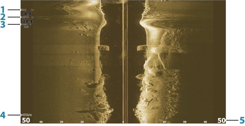
6 Preface | Hook Reveal Series Operator Manual
Contents
11 Introduction
11   Front controls
12   The Home page
13   Application pages
14   Device registration

15 Basic operation
15   Turning the system on and off
15   System Controls dialog
16   Standby mode
16   Display illumination
16   Using menus and dialogs
17   Using the cursor on the panel
17   Man Overboard waypoint
18   Screen capture

19 Customizing your system
19   Customizing the Home page wallpaper
19   Data overlay
20   Custom pages
21   Adjusting the split on multiple panel pages

23 Charts
23   The Chart panel
23   Chart data
24   Selecting chart type
24   Vessel symbol
24   Chart scale
24   Panning the chart
24   Waypoints, Routes, and Trails
24   Navigating
24   Displaying information about chart items
25   Find objects on chart panels
26   More options
28   C-MAP charts
29   Navionics charts
33   Chart settings

     Contents | Hook Reveal Series Operator Manual   7
35 Waypoints, routes, and trails
    35   Waypoints, Routes, and Trails dialogs
    35   Waypoints
    37   Routes
    41   Trails

    44 Navigating
    44   About navigating
    44   Menu options
    44   Navigate to cursor position
    45   Navigate to a waypoint
    45   Navigate a route
    45   Navigation settings

    47 Sonar
    47   The Sonar image
    47   Zooming the image
    48   Using the cursor on the image
    48   Viewing history
    48   Start recording sonar log data
    49   Stop recording sonar log data
    50   Viewing the recorded sounder data
    50   Customize the image settings
    50   Custom and Ice Fishing mode options
    53   More options
    55   Sonar settings

    58 SideScan
    58   About SideScan
    58   The SideScan image
    58   Zooming the image
    59   Using the cursor on the panel
    59   Viewing history
    60   Recording SideScan data
    60   Setting up the SideScan image

    63 DownScan
    63   About DownScan

8        Contents | Hook Reveal Series Operator Manual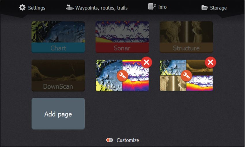
63   The DownScan panel
63   Zooming the DownScan image
63   Using the cursor on the DownScan panel
64   Viewing DownScan history
64   Recording DownScan data
64   Customize the image settings

68 StructureMap
68   About StructureMap
68   The StructureMap image
69   StructureMap tips
69   Recording StructureMap data
69   Using StructureMap with mapping cards
70   Structure options

71 Alarms
71   Alarm system
71   Type of messages
71   Alarm messages
71   Acknowledging a message
72   Alarms dialog

73 Tools
73   Settings
76   Waypoints/routes/trails
76   Info
76   Storage

77 Maintenance
77   Preventive maintenance
77   Cleaning the display unit
77   Checking the connectors
77   Service assistant
78   Software updates
78   Backing up your system data
81   Importing backed up files

82 Simulator
82   Retail mode

     Contents | Hook Reveal Series Operator Manual   9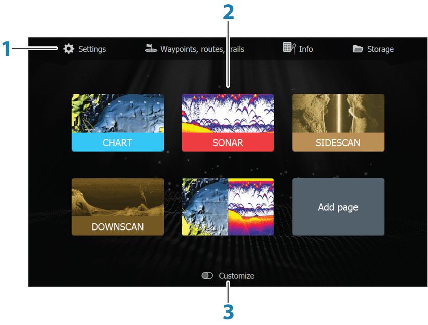
82   Simulator source files
     83   Advanced simulator settings

10        Contents | Hook Reveal Series Operator Manual
1
Introduction
Front controls
1 2
3
4 5
6 7
1 Pages - Press to activate the Home page.
2 Zoom in/out - Press to zoom the image.
Press both keys simultaneously to create a MOB (Man Over
Board) waypoint at the vessel's position.
3 Arrows - On any full screen page: press to position the
cursor on the image. Press to pan the image in any direction.
On multiple panel pages: press to select a panel.
In menus and dialogs: press to highlight an option.
4 Exit (X) - On a maximized multiple panel page: press to
return to the multiple panel page.
In menus and dialogs: press to return to previous menu level
and to exit a dialog.
5 Menu/Enter - On any full screen page with no menu or
dialog active: press to display the menu.
On multiple panel pages: press to maximize the current
selected panel.
In menus and dialogs: press to confirm a selection.
6 Cursor/Waypoint - Press to activate/deactivate the cursor.
Press and hold to save a waypoint.
7 Power - Press to display the System Controls dialog.
Press and hold to power the unit on/off.
Micro SD card
Depending on model the card reader is located either on the side or
on the front.
Introduction | Hook Reveal Series Operator Manual 11The Home page
The Home page is accessed from any operation by a short press on
the Pages key.
Ú Note: Page icons on the Home page vary with model type.
1 Tools panel - Select a button to access dialogs used for
carrying out a task, or for browsing stored information.
2 Application page icons - Select a button to display the
application page.
3 Customize - Activate customize mode to delete or modify
custom pages.
12 Introduction | Hook Reveal Series Operator ManualApplication pages
1 Application panel
2 Menu - Panel specific menu.
3 System Controls dialog - Quick access to basic system
settings.
4 Dialog - Information to or input from the user.
5 Alarm message - Displayed if dangerous situations or
system faults occur.
Each application connected to the system is presented on panels.
The application can be presented as a full page, or in combination
with other panels in a multiple panel page.
All application pages are accessed from the Home page.
Custom pages
The system is delivered with one preconfigured custom page, and
you can create your own. All custom pages can be modified and
deleted. To add a custom page, refer to "Adding new custom pages" on
page 20.
To edit or delete a custom page, refer to "Edit or delete custom pages" on
page 21.
Multiple panel custom pages
You can have up to 4 panels on a custom page. Refer to "Adding new
custom pages" on page 20.
Introduction | Hook Reveal Series Operator Manual 132 panels page 3 panels page 4 panels page
Panel sizes in a multiple panel page can be adjusted from the
System Controls dialog. Refer to "Adjusting the split on multiple panel pages"
on page 21.
• With the cursor not active on any panel, switch active panel by
using the Arrow keys. An active panel is indicated with an orange
border.
• Maximize the active panel by pressing the Menu/Enter key. Press
the Exit (X) key to go back to the multiple panel page.
• To display the panel menu, it must first be maximized. Once
maximized, press the Menu/Enter key (again) to display the
menu for the maximized pane. Press the Exit (X) key to close the
menu, press the Exit (X) key again to go back to the multiple
panel page.
• Activate the cursor on the active or maximized panel by pressing
the Cursor/Waypoint key, then use the Arrow keys to position the
cursor. Press the Cursor/Waypoint key again to remove the
cursor.
Device registration
You are prompted to register your device during startup. You can
also register by selecting the register option in the System settings
dialog. Registration can be done:
• From a smart device with internet access
• Over the phone
14 Introduction | Hook Reveal Series Operator Manual2
Basic operation
Turning the system on and off
The system is turned on by pressing the Power key.
Press and hold the Power key to turn the unit off.
If the key is released before the shut-down is completed, the power
off process is cancelled.
You can also turn the unit off from the System Controls dialog.
First time startup
When the unit is started for the first time, or after a reset, the unit
displays a series of dialogs. Respond to the dialog prompts to make
fundamental settings.
You can perform further setup and later change settings using the
system settings dialogs.
System Controls dialog
The System Controls dialog provides quick access to basic system
settings. You display the dialog by making a short press on the
Power key.
The icons displayed on the dialog can vary. For example, the adjust
splits option is only available if you are viewing a multiple panel
page when you open the System Controls dialog.
Activating functions
Select the icon of the function you want to set or toggle on or off.
For those functions that toggle on and off, an orange bar across the
top of the icon indicates the function is activated, as shown in the
Data overlay icon above.
Basic operation | Hook Reveal Series Operator Manual 15Standby mode
In Standby mode, the Sonar and the backlight for the screen are
turned off to save power. The system continues to run in the
background.
You select Standby mode from the System Controls dialog.
Switch from Standby mode to normal operation by a short press on
the Power key.
Display illumination
Brightness
You can cycle the preset backlight levels by short presses on the
Power key.
The display backlighting can also be adjusted from the System
Controls dialog.
Night mode
The night mode can be activated from the System Controls dialog.
The night mode option optimizes the color palette for low light
conditions.
Using menus and dialogs
Menus
The menu is used to operate the system and to adjust settings.
Press the Menu/Enter key to display the page menu. Press the
Menu/Enter key again to close the menu.
Use the Arrow keys to highlight a menu option, then press the
Menu/Enter key to confirm the selection.
Scroll bars - activate the scroll bar in the menu and use the Arrow
keys to adjust it. Press the Menu/Enter key to save your adjustment.
The status of the cursor (active vs. inactive) changes the menu
options.
Dialog boxes
Use the Arrow keys to highlight a dialog option, then press the
Menu/Enter key to confirm the selection.
16 Basic operation | Hook Reveal Series Operator ManualNumeric and alphanumeric keyboards are automatically displayed when required for entering user information in dialogs. A dialog is closed by saving or cancelling the entry. A dialog can also be closed by pressing the Exit (X) key. Using the cursor on the panel The cursor can be used to mark a position, and to select items. By default, the cursor is not shown on the panel. Display the cursor by pressing the Cursor/Waypoint key and use the Arrow keys to move the cursor on the panel. When the cursor is active on the chart panel, the cursor position window is displayed. The bottom line of the window shows the distance and heading from the vessel to the cursor. When the cursor is active on the sonar panel, the window also shows the depth and temperature at the cursor. To remove the cursor and cursor elements from the panel, press the Cursor/Waypoint key. Man Overboard waypoint If an emergency situation should occur, you can save a Man Overboard (MOB) waypoint at the vessel’s current position. Create a MOB To create a Man Overboard (MOB) waypoint: • Simultaneously press the Zoom In (+) and Zoom out (-) keys When you activate the MOB function, the following actions are automatically performed: • A MOB waypoint is created at the vessel’s position • The display switches to a zoomed chart panel, centered on the vessel's position • The system displays navigation information back to the MOB waypoint Multiple MOB waypoints can be created. The vessel continues to show navigation information to the initial MOB waypoint. Navigation to subsequent MOB waypoints needs to be done manually. Basic operation | Hook Reveal Series Operator Manual 17
Delete a MOB
     A MOB waypoint can be deleted from the menu when the MOB is
     activated.

     Stop navigating to MOB
     The system continues to display navigational information towards
     the MOB waypoint until you cancel the navigation from the menu.

     Screen capture
     To take a screen capture:
     • Simultaneously press the pages key and the power key

18   Basic operation | Hook Reveal Series Operator Manual
3
Customizing your system
Customizing the Home page wallpaper
The Home page's wallpaper can be customized. You can select one
of the pictures included with the system, or you can use your own
picture in .jpg or .png format.
The images can be available on any location that can be seen in the
files browser. When a picture is chosen as the wallpaper, it is
automatically copied to the Wallpaper folder.
Data overlay
You can have data information as overlay on a page.
Turning Data overlay on and off
You can turn overlay data on or off for any active page by selecting
the Data overlay icon on the System Controls dialog. When Data
overlay is on, an orange bar appears above the icon.
Edit overlay data
Use the Edit overlay option on the System Controls dialog to access
edit menu options to:
• Add a new data overlay to the active panel.
• Delete a selected data overlay.
• Change a selected data overlay to display different data.
Customizing your system | Hook Reveal Series Operator Manual 19• Configure a selected data overlay appearance (digital or analog,
size, etc.).
• Re-locate an item by selecting it and then the Move menu
option. Use the Arrow keys to move selected item.
Custom pages
Adding new custom pages
A maximum of 9 pages are allowed. You can have up to 4 panels on
a custom page.
1. Select the add page icon on the Home page to open the page
editor dialog
2. Use the Arrow keys to highlight a panel, then press the Menu/
Enter key. The panel is added to the page.
3. (Optional) Repeat step 2 to add additional panels. A maximum
of 4 panels are allowed.
- To change the layout: use the Arrow keys to select the layout
option. Use this option to specify how you want the panels
displayed.
- To remove a panel: use the Arrow keys to select the pane on
the right side of the dialog and to highlight the delete (X) icon
in the top right corner of the panel. Press the Menu/Enter key.
The panel is removed from the pane on the right side of the
dialog.
- To move a panel: use the Arrow keys to select the pane on the
right side of the dialog and to highlight the arrows icon in the
top left corner of the panel you want to move. Press the
Menu/Enter key. A larger arrows icon is displayed. Use the
20 Customizing your system | Hook Reveal Series Operator
ManualArrow keys to move the highlighted panel. Press the Menu/
Enter key to save your adjustment.
4. Save the page layout.
The system displays the new custom page, and an icon for the new
page is included on the Home page.
Edit or delete custom pages
1. On the Home page, use the Arrow keys to highlight the
customize option and press the Enter/Menu key to turn ON the
customize option.
2. Use the Arrow keys to:
- Select the X option on a custom page icon, and press the
Menu/Enter key to remove the page
- Select the tool option on a custom page icon, and press the
Menu/Enter key to display the page editor dialog
3. Change the layout, add, and remove panels using the custom
page editor dialog. Refer to Step 3 in "Adding new custom pages" on
page 20.
4. Save or discard your changes to leave edit mode.
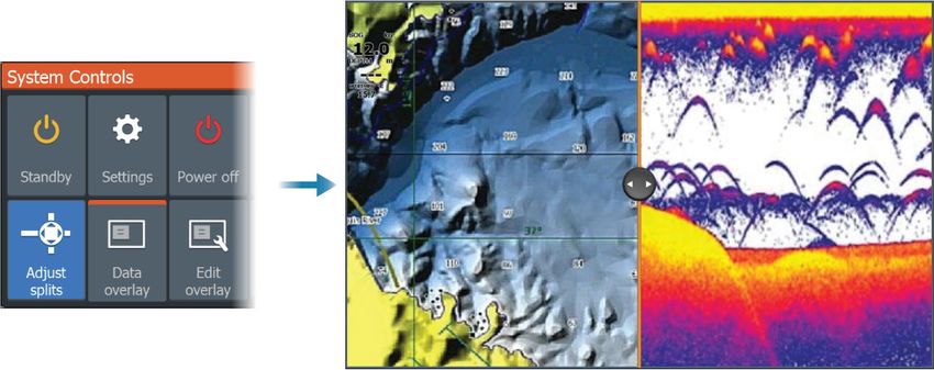
Adjusting the split on multiple panel pages
1. Open the multiple panel page
2. Quick-press the Power key to open the System Controls dialog
3. Select the Adjust splits option. The cursor arrows icon appears
on the multiple panel page.
4. Use the Arrow keys to move the split to the desired position
5. Press the Menu/Enter key to save the split adjustment.
Customizing your system | Hook Reveal Series Operator Manual 2122 Customizing your system | Hook Reveal Series Operator
Manual4
Charts
The Chart panel
A North indicator
B Vessel
C Chart range scale
D Grid lines*
E Range rings*
* Optional chart items. Optional chart items can be turned on/off
individually from the chart settings dialog.
Chart data
The system can be delivered with preloaded cartography.
For a full selection of supported charts, visit the product web site.
Ú Note: Chart menu options vary depending on the chart you are
using.
Ú Note: The system does not automatically switch to preloaded
cartography if the chart card is removed. A low-resolution chart
will be displayed until you re-insert the card or manually switch
back to the preloaded cartography.
Charts | Hook Reveal Series Operator Manual 23Selecting chart type
You specify the chart type shown on the Chart panel by selecting
one of the available chart types in the chart settings dialog. Refer to
"Chart settings" on page 33.
Vessel symbol
When the system has a valid GPS position lock, the vessel symbol
indicates vessel position. If no GPS position is available, the vessel
symbol includes a question mark.
Chart scale
You zoom in and out on the chart by using the Zoom keys.
Chart range scale and range rings interval (when turned on) are
shown in the lower right corner of the chart panel.
Panning the chart
You can move the chart in any direction by using the Arrow keys to
move the cursor to the edge of the chart panel in the desired
direction.
To remove the cursor and cursor elements from the panel, press the
Cursor/Waypoint key. This also centers the chart to the vessel
position.
Waypoints, Routes, and Trails
You can position and manage waypoints, routes and trails on the
page. For more information, refer to "Waypoints, routes, and trails" on page
35.
Navigating
You can use the page for navigating to the cursor, to a waypoint, or
navigate a route. Refer to "Navigating" on page 44.
Displaying information about chart items
When you position the cursor over a chart item, waypoint, trail or a
route, basic information for the selected item is displayed as a pop-
up.
24 Charts | Hook Reveal Series Operator ManualÚ Note: Pop-up information has to be enabled in chart settings to see basic item information. Select the info option in the menu to display a list of items near the cursor. Select an item in the list to display all available information for that item. Find objects on chart panels Select the find menu option to search for chart items. Charts | Hook Reveal Series Operator Manual 25
More options
     Chart overlay
     You can add overlays on the chart panel.
     When an overlay is selected, the chart menu expands to include
     basic menu options for the selected overlay.
     Information about the overlay menu options are described in more
     detail below or in their separate sections in this manual.

     Structure overlay
     Structure (StructureMap) information can be displayed as overlay on
     your chart panel.
     Ú Note: Structure overlay (StructureMap) is only available on
       TripleShot models that have SideScan capability.
     When Structure overlay is selected, the chart menu expands to
     include basic menu functions for the overlay. Refer to "StructureMap"
     on page 68.

     Genesis live
     Ú Note: Only available when viewing Lowrance or C-MAP chart
       source.
     Genesis live is a real-time feature where the unit creates an overlay
     of depth contour mapping based on live sonar soundings. The
     Genesis live sonar soundings are recorded onto and viewed from
     the unit's memory card.
     If at any time the memory card is removed or runs out of space, the
     feature will turn itself off and the option is disabled in the menu.
     • The more passes of an area included in the live sonar soundings
         log, results in better Genesis live maps.
     • Genesis live is accurate up to 20 knots.
     Ú Note: Genesis Live data is not adjusted for tidal offset.

26   Charts | Hook Reveal Series Operator Manual
Genesis live menu options
Transparency
Adjusts the transparency of the overlay.
Contour interval
Defines the density of live depth contours shown.
Depth palette
Controls the color palette used to color the depth areas.
• Chart sync – syncs the Genesis live layer to the same palette as
the chart depth palette defined in the chart menu (under Chart
options, View, Depth palette). This option also allows custom
palettes to be defined in the chart menu and applied to the
Genesis layer.
• Navigation – uses the navigation palette.
• Depth shading – uses the depth shading palette.
• Paper chart – uses the paper chart palette.
• Safety shading – uses the safety depth setting to shade the color
lower than the set safety depth. Also enables the Safety depth
option on the Genesis live menu.
Safety depth
Sets the safety depth. Areas that are shallower than the safe
minimum depth are shaded. This option is only available if the
Safety shading palette is selected.
Chart orientation
You can specify how the chart is rotated in the panel. The chart
orientation symbol in the panel’s upper right corner indicates the
north direction.
North up Course up
Charts | Hook Reveal Series Operator Manual 27North up
Displays the chart with north upward.
Course up
The chart direction is depending on if navigating or not:
• when navigating: the desired course line is oriented up
• if not navigating: the direction the vessel is actually traveling
(COG) is oriented up
Look ahead
Moves the vessel icon on the panel to maximize your view ahead of
the vessel.
C-MAP charts
All possible menu options for C-MAP charts are described below.
The features and menu options available can vary depending on the
charts you use. This section shows menus from a C-MAP chart.
Ú Note: A menu option is greyed out if the feature is not available
on the chart displayed.
C-MAP specific chart options
Chart detail
• Full - displays all available information for the chart in use.
• Medium - displays minimum information sufficient for
navigation.
• Low - displays basic level of information that cannot be removed,
and includes information that is required in all geographic areas.
It is not intended to be sufficient for safe navigation.
Genesis Layer
The Genesis Layer displays high-resolution contours contributed by
Genesis users that have passed a quality check.
This option toggles the Genesis layer on/off on the chart image.
Available only if the C-MAP chart contains Genesis Layer data.
28 Charts | Hook Reveal Series Operator ManualDepth palette Controls the Depth palette used on the map. Depth filter Filters out depth values shallower than the selected depth filter limit. Safety depth Charts use different shades of blue to distinguish between shallow (lighter shades) and deep (darker shades) water. After enabling the safety shading depth palette, specify the desired safety depth limit. The Safety depth sets the limit at which depths will be drawn without blue shading. Chart categories Several categories and sub-categories are included. You can turn on/off the categories individually depending on which information you want to see. Navionics charts Some Navionics features require the most current data from Navionics. For those features, a message is displayed stating that the feature is unavailable if you do not have the appropriate Navionics charts or chart card inserted. For more information on what is required for these features, refer to www.navionics.com. Charts | Hook Reveal Series Operator Manual 29
You can also get a message if you try to use a restricted feature
     when the Navionics chart card is not activated. To activate the card,
     contact Navionics.

     Navionics specific chart options
     Chart overlay, orientation, and look ahead options (previously
     described in this section) are common to both C-MAP and
     Navionics charts. The following describe Navionics specific chart
     options.

     Community edits
     Toggles on the chart layer including Navionics edits. These are user
     information or edits uploaded to Navionics Community by users,
     and made available in Navionics charts.
     For more information, refer to Navionics information included with
     your chart, or to Navionics website: www.navionics.com.

     SonarChart
     The system supports the Navionics SonarChart feature.
     SonarChart displays a bathymetry map showing high resolution
     contour detail and standard navigational data. For more
     information, refer to www.navionics.com.

     SonarChart Live
     SonarChart Live is a real-time feature where the device creates an
     overlay of depth contours based on your own live sonar soundings.
     When you select SonarChart Live overlay the menu expands to
     display SonarChart Live options.

     Transparency
     The SonarChart Live overlay is drawn on top of other chart data. The
     chart data is completely covered at minimum transparency. Adjust
     the transparency to allow the chart details to be seen.

     Minimum depth
     Adjusts what SonarChart Live rendering treats as the safety depth.
     This affects the coloring of the SonarChart Live area. As the vessel
     approaches the safety depth, the SonarChart Live area will gradually
     change from a simple grey/white to red.

30   Charts | Hook Reveal Series Operator Manual
SCL History
Select to display previously recorded data on the chart overlay.
SC Density
Controls the density of the SonarChart and SonarChart Live
contours.
Navionics Dynamic tides and current icons
Shows tides and currents with a gauge and an arrow instead of the
diamond icons used for static tides and current information.
The tide and current data available in Navionics charts are related to
a specific date and time. The system animates the arrows and/or
gauges to show the tides and currents evolution over time.
Dynamic tide information Dynamic current information
The following icons and symbology are used:
Current speed
The arrow length depends on the rate, and the symbol is rotated
according to flow direction. Flow rate is shown inside the arrow
symbol. The red symbol is used when current speed is increasing,
and the blue symbol is used when current speed is decreasing.
Tide height
The gauge has 8 labels and is set according to absolute max/min
value of the evaluated day. The red arrow is used when tide is rising,
and the blue arrow is used when tide is falling.
Ú Note: All numeric values are shown in the relevant system units
(unit of measurement) set by user.
Charts | Hook Reveal Series Operator Manual 31Easy View
Magnifying feature that increases the size of chart items and text.
Ú Note: There is no indication on the chart showing that this
feature is active.
Fishing range
Select a range of depths between which Navionics fills with a
different color.
This allows you to highlight a specific range of depths for fishing
purposes. The range is only as accurate as the underlying chart data,
meaning that if the chart only contains 5 meter intervals for contour
lines, the shading is rounded to the nearest available contour line.
No Depth highlight range Depth highlight range: 6 m - 12 m
Shallow water highlight
This highlights areas of shallow water between 0 and the selected
depth (up to 10 meters/30 feet).
No shallow water highlighted Shallow water highlight: 0 m - 3 m
32 Charts | Hook Reveal Series Operator ManualPresentation type Displays marine charting information such as symbols, colors of the navigation chart and wording for either International or U.S. presentation types. Safety depth The Navionics charts use different shades of blue to distinguish between shallow and deep water. Safety depth, based on a selected limit, is drawn without blue shading. Ú Note: The built in Navionics database features data down to 20 m, after which it is all white. Chart details Provides you with different levels of geographical layer information. Chart settings Select the settings option in the System Controls dialog to access the chart settings dialog. Chart source Change chart source if a chart card is inserted. Charts | Hook Reveal Series Operator Manual 33
Pop-up information
     Determines whether basic information for panel items is displayed
     when you select the item.

     Range rings
     The range rings can be used to present the distance from your
     vessel to other panel objects.
     The range scale is set automatically by the system to suit the panel
     scale.

     Grid lines
     Turns on/off viewing of longitude and latitude grid lines on the
     panel.

     Waypoints, Routes, Trails
     Turns on/off displaying these items on panels.

     Course extension line
     Turns on/off displaying the Course Over Ground (COG) extension
     line on the panel. The COG is based on information from the GPS.

     Extension line length
     When the course extension option is turned on, specify the length
     of the line to be displayed.

     SonarChart Live tide correction
     When selected, the tide correction feature uses information from
     nearby tide stations (if available) to adjust the depth values used by
     SonarChart Live as the sonar is recorded.

34   Charts | Hook Reveal Series Operator Manual
5
Waypoints, routes, and trails
Waypoints, Routes, and Trails dialogs
The Waypoints, Routes, and Trails dialogs give access to advanced
edit functions and settings for these items.
The dialogs are accessed from the Tools panel on the Home page.
Select the menu icon on the dialog to access additional options.
Waypoint options Routes options Trails options
Waypoints
A waypoint is a user generated mark positioned on the chart panel.
Waypoints, routes, and trails | Hook Reveal Series Operator
Manual
35Each waypoint has an exact position with latitude and longitude
coordinates. A waypoint is used to mark a position you later may
want to return to. Two or more waypoints can also be combined to
create a route.
Saving waypoints
Press and hold the Cursor/Waypoint key to save a new waypoint.
• With cursor inactive, the waypoint is placed at the vessel's
position
• With cursor active, the waypoint is placed at the cursor position
Moving a waypoint
1. Press the Cursor/Waypoint key.
2. Maneuver the cursor so it is over the waypoint
3. Activate the menu and select the waypoint in the menu. The
menu expands to include the move option.
4. Select the move option in the menu
5. Use the Arrow keys to move the waypoint to the new position
6. Press the Menu/Enter key.
The waypoint is saved at the new position.
Edit a waypoint
You can edit all information about a waypoint from the Edit
Waypoint dialog.
The dialog is activated by positioning the cursor over the waypoint,
selecting the waypoint in the menu, and then the Edit menu option.
The dialog can also be accessed by activating the Waypoints,
Routes, Trails dialog on the tools panel on the Home page. Select
the Waypoints tab and then the waypoint you want to edit.
36 Waypoints, routes, and trails | Hook Reveal Series
Operator ManualDelete a waypoint
You can delete a waypoint from the Edit Waypoint dialog or by
selecting the Delete menu option when the waypoint is activated.
The Edit Waypoint dialog is activated by positioning the cursor over
the waypoint, selecting the waypoint in the menu, and then the
delete menu option.
The Edit Waypoint dialog can also be accessed by activating the
Waypoints, Routes, Trails dialog on the tools panel on the Home
page. Select the Waypoints tab, the waypoint you want to delete
and then the delete option.
You can delete MOB waypoints the same way.
Waypoint alarm settings
You can set an alarm radius for each individual waypoint you create.
The alarm is set in the Edit Waypoint dialog.
Ú Note: The waypoint radius alarm must be toggled ON in the
alarm dialog to activate an alarm when your vessel comes
within the defined radius. For more information, refer to "Alarms
dialog" on page 72.
Routes
A route consists of a series of routepoints entered in the order that
you want to navigate them.
When you select a route on the panel it turns green, and the route
name is displayed.
Creating a new route on the page
1. Select the new route option from the menu
2. Press the Cursor/Waypoint key to activate the cursor on the
panel
3. Use the Arrow keys to position the cursor at the first routepoint
on the panel
4. Press the Menu/Enter key to create the routepoint
5. Repeat steps 3 and 4 to continue positioning new routepoints
on the panel until the route is completed
6. Press the Exit (X) key when completed and save the route.
Waypoints, routes, and trails | Hook Reveal Series Operator
Manual
37Edit a route from the panel
You can edit a route by placing the cursor over the route and then
selecting the route in the menu. Select the edit option in the menu.
This opens the Edit route dialog.
The dialog can also be accessed by activating the Waypoints,
Routes, Trails dialog on the tools panel on the Home page. Select
the Route tab and then the route you want to edit.
To edit the route from the panel:
1. Maneuver the cursor over the route in the panel. The route pop-
up is displayed.
2. Press the Menu/Enter key and use the Arrow keys to select the
route in the menu. The menu expands with additional options.
- The edit option allows you to move and remove routepoints
on the panel.
- The details option opens the edit route dialog where you can
set route options, rename and manage details.
3. Use the Arrow keys to select the option you want to use and
press the Menu/Enter key.
4. Follow the prompts to make changes and save your changes.
Delete a route
You can delete a route by placing the cursor over the route and
then selecting the route in the menu and then select the delete
option in the expanded menu.
38 Waypoints, routes, and trails | Hook Reveal Series
Operator ManualCreating routes using existing waypoints
You can create a new route by combining existing waypoints from
the New Routes dialog.
The dialog is activated by selecting the route tab in the dialog
displayed when you select the Waypoint, Routes, and Trails tool on
the Home page. Next, select the New route option.
You can also insert existing waypoints in an existing route from the
Edit Routes dialog.
From the Edit Routes dialog, select the routepoint in the list where
you want to insert the waypoint and press the Menu/Enter key.
Waypoints, routes, and trails | Hook Reveal Series Operator
Manual
39Converting trails to routes
You can convert a trail to a route from the Edit Trail dialog. The
dialog is activated by activating the trail, then selecting the trail's
pop-up, or the Trail menu option.
The Edit Trail dialog can also be accessed by selecting the
Waypoints tool on the Home page.
The Edit Route dialog
You can add and remove routepoints, and change route properties
using the Edit Route dialog.
This dialog is activated by placing the cursor over the route and
selecting the route in the menu.
The dialog can also be accessed by selecting the route tab in the
dialog displayed when you select the Waypoint, Routes, and Trails
tool on the Home page.
Select the name field to change the name. Turn on Display to show
the route on the panel.
40 Waypoints, routes, and trails | Hook Reveal Series
Operator ManualTrails
Trails are a graphical presentation of the historical path of the vessel,
allowing you to retrace where you have travelled.
Trails can be converted to routes from the Edit Trails dialog. Refer to
"Converting trails to routes" on page 40.
From the factory, the system is set to automatically track and draw
the vessel's movement on the panel. The system continues to
record the trail until the length reaches the maximum points, and
then automatically begins overwriting the oldest points.
The automatic tracking function (record) can be turned off from the
Edit Trails dialog.
Waypoints, routes, and trails | Hook Reveal Series Operator
Manual
41Creating new Trails
You can start a new trail from the Trails dialog, activated by using
the Waypoints, Routes, Trails tool on the Home page and selecting
the Trails tab.
Trails settings
Trails are made up of a series of points connected by line segments
whose length depends on the frequency of the recording.
You can select to position trail points based on time settings,
distance, or by letting the system position a trail point automatically
when a course change is registered.
Ú Note: The Trails option must also be turned ON in the panel
settings dialog to be visible.
Coloring trails
To color trails:
• Select the trail in the Trails dialog and set the color for the entire
trail in the Edit Trail dialog.
42 Waypoints, routes, and trails | Hook Reveal Series
Operator ManualWaypoints, routes, and trails | Hook Reveal Series Operator
Manual
436
Navigating
About navigating
The navigation function included in the system allows you to
navigate to the cursor position, to a waypoint, or along a predefined
route.
For information about positioning waypoints and creating routes,
refer to "Waypoints, routes, and trails" on page 35.
Menu options
You can use menu options to:
• navigate to cursor
• navigate to a waypoint
• navigate a route
While navigating, the menu expands to provide options to:
• skip waypoints when navigating a route
• restart navigating to cursor, a waypoint or a route
• cancel navigating to cursor, a waypoint or a route
Navigate to cursor position
You can start navigating to a cursor position on any chart/GPS
plotter or sonar panel.
Position the cursor at the selected destination on the panel, and
then select the Goto Cursor option in the menu.
Ú Note: The Goto Cursor menu option is not available if you are
already navigating.
44 Navigating | Hook Reveal Series Operator ManualNavigate to a waypoint You can start navigating towards a waypoint on the panel. Position the cursor over the waypoint, select the waypoint in the menu and then the Goto waypoint option in the menu. Navigate a route You can navigate a route on the image by positioning the cursor over the route, selecting the route in the menu and then the start route option in the menu. When route navigation is started, select the Navigation menu option for canceling the navigation, skipping a waypoint, and restarting the route from current vessel position. Navigation settings Arrival radius Sets an invisible circle around the destination waypoint. The vessel is considered arrived at the waypoint when it is within this radius. Navigating | Hook Reveal Series Operator Manual 45
XTE limit
     This setting defines how far the vessel can deviate from the selected
     route, if the vessel goes beyond this limit, an alarm is activated.

     XTE alarm (Cross track error)
     Turns on/off the XTE alarm.

     Trails
     Opens the Trails dialog where trails settings can be adjusted and
     trails can be converted into routes for navigation. Refer to "Trails" on
     page 41.

     Logging type
     You can select to record trail points based on time, distance, or by
     letting the unit position a point automatically when a course
     change is registered.
     Specify one of the following logging types in the Navigating
     Settings dialog:
     • Auto - the unit positions a point automatically when a course
        change is registered.
     • Distance - select the Distance field and enter the distance you
        want to record.
     • Time - select the Time field and enter the time you want to
        record.

46   Navigating | Hook Reveal Series Operator Manual
7
Sonar
The Sonar function provides a view of the water and bottom
beneath your vessel, allowing you to detect fish and examine the
structure of the bottom.
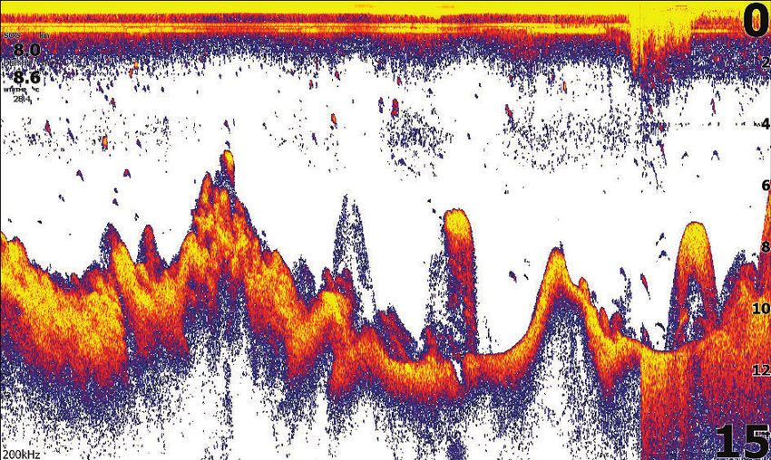
The Sonar image
1
2
3
4
5
6 7
1 Fish arches
2 Speed over ground*
3 Depth*
4 Water Temperature*
5 Frequency
6 Bottom
7 Range scale
* Optional Sonar data overlay that you can modify. Refer to "Data
overlay" on page 19.
Zooming the image
You can zoom the image by using the Zoom keys.
The zoom level is shown on the bottom left side of the image.
Sonar | Hook Reveal Series Operator Manual 47When zooming with no active cursor, the sea floor is kept near the
bottom of the screen. If the cursor is active, the unit zooms where
the cursor is pointed.
You can also zoom the image as a split screen and display zoom
bars. Refer to split screen "Zoom" on page 53.
Using the cursor on the image
When you position the cursor on the image the screen pauses, the
depth at the cursor position is shown, and the information window
and the history bar are activated.
Viewing history
You can view sonar history by panning the image. To pan the
image, position the cursor on the image. This stops automatic
scrolling.
• Use the left Arrow key to move the cursor to left edge of the
image. Continue pressing the left Arrow key so the image pans to
the left and the historical image is viewed.
• Use the right Arrow key in the same manner to pan the image
back to the right and display the most current image.
• To resume normal scrolling, press the Cursor/Waypoint key to
remove the cursor from the image.
Start recording sonar log data
You can start recording sonar log data and save the file internally in
the unit, or save it onto a card inserted into the unit’s card reader.
The Log sonar dialog is activated from the System Controls, or from
the Sonar Settings dialog.
48 Sonar | Hook Reveal Series Operator ManualWhen the data is being recorded, there is a flashing red symbol in the top left corner and a message appears periodically at the bottom of the screen. Filename Specify the name of the recording (log). File format Select a file format from the drop-down, slg (Sonar only), xtf (Structure only*), or sl2 (Sonar and Structure). Ú Note: XTF format is for use only with select 3rd party Sonar viewing tools. Save to Select whether the recording is to be saved internally or to a storage device connected to the unit. Create StructureMap Ú Note: This option is only available on TripleShot models that have SideScan capability. You can convert the SideScan (.sl2) logs to StructureMap format (.smf) when recording completes. SideScan log files can also be converted to StructureMap format using the Storage toolbar feature. Time remaining Shows the remaining allocated space available for recordings. Stop recording sonar log data Select Stop logging in the System Controls dialog and then Stop in the Logging Sonar dialog to stop the recording of all sonar log data. Sonar | Hook Reveal Series Operator Manual 49
Viewing the recorded sounder data
     Both internally and externally stored sounder records may be
     reviewed when the view sonar log option is selected in the Sonar
     settings dialog. Refer to "Sonar settings" on page 55.

     Customize the image settings
     By default the unit is set to Auto mode, and most settings are
     automated. It is recommended that only experienced sonar users
     use the customize settings to further customize the image.
     Select Auto in the menu and change to custom or ice fishing mode
     to customize image settings.
     Use More options in the menu, to set access additional options for
     the image. Refer to "More options" on page 53.

     Custom and Ice Fishing mode options
     Custom and Ice fishing modes allow access to controls for manually
     tuning the sonar.
     Ú Note: The options below are only visible in Custom or Ice
       Fishing modes.

50   Sonar | Hook Reveal Series Operator Manual
The range The range setting determines the water depth that is visible on the screen. Frequency The unit supports several transducer frequencies. Available frequencies depend on the transducer model that is connected. Sensitivity Increasing Sensitivity shows more detail on the screen. Decreasing Sensitivity displays less. Too much detail clutters the screen. Conversely, desired echoes may not be displayed if Sensitivity is set too low. Ú Note: Auto Sensitivity is the preferred mode for most conditions. Auto sensitivity Auto sensitivity automatically adjusts the sonar return to the optimal levels. Auto sensitivity can be adjusted (+/-) to your preference while still maintaining the auto sensitivity functionality. Adjusting Sensitivity 1. Select the Auto sensitivity menu option to turn off the auto setting. 2. Use the Arrow keys to highlight the scroll bar menu option. 3. Press the Menu/Enter key to activate it. 4. Use the Arrow keys to adjust it. 5. Press the Menu/Enter key to confirm the setting. 6. Press the Exit (X) key to leave the menu. Sonar | Hook Reveal Series Operator Manual 51
Advanced options

     Ping speed
     Ping speed controls the rate the transducer transmits the signal into
     the water. By default, the ping speed is set to max. It may be
     necessary to adjust the ping speed to limit interference.

     Scroll speed
     You can select the scrolling speed of the image on the screen. A
     high scroll speed updates the image fast, while a low scroll speed
     presents a longer history.
     Ú Note: In certain conditions it may be necessary to adjust the
       scroll speed to get a more useful image. Such as adjusting the
       image to a faster speed when vertically fishing without moving.

     Noise rejection
     Signal interference from bilge pumps, engine vibration and air
     bubbles can clutter the image.
     The noise rejection option filters the signal interference and reduces
     the on-screen clutter.

     Surface clarity
     Wave action, boat wakes, and temperature inversion can cause
     onscreen clutter near the surface. The surface clarity option reduces
     surface clutter by decreasing the sensitivity of the receiver near the
     surface.

     Colorline
     Allows the user to adjust the colors of the display to help
     differentiate softer targets from harder ones. Adjusting the Colorline
     can help separate fish and important structures on or near the
     bottom from the actual bottom.
     Use the up and down Arrow keys to adjust the scroll bar.

     Restore mode default
     This menu option is available if you customize one or more settings.
     When selected all the customized settings are changed back to the
     default settings.

52   Sonar | Hook Reveal Series Operator Manual
More options
Split screen options
Split screen options are available on the split screen sub-menu.
Zoom
1 2
1 Zoom level
2 Zoom bars
The Zoom mode presents a magnified view of the sounder image
on the left side of the panel. By default, the zoom level is set to 2x.
You can zoom up to 8x, using the Zoom keys. The range zoom bars
on the right side of the display shows the range that is magnified. If
you increase the zooming factor the range is reduced. You see this
as reduced distance between the zoom bars.
Bottom lock
The bottom lock mode is useful when you want to view targets
close to the bottom. In this mode, the left side of the panel shows
an image where the bottom is flattened. The range scale is changed
to measure from the seabed (0) and upwards. The bottom and the
zero line are always shown on the left image, independent of the
Sonar | Hook Reveal Series Operator Manual 53range scale. The scaling factor for the image on the left side of the
panel is adjusted as described for the Zoom option.
Flasher
The Flasher mode shows a flasher-style sonar view in the left panel
and a normal sonar view in the right panel.
Amplitude scope
The amplitude scope is a display of an echo sounding on the panel.
The strength of the actual echoes are indicated by both width and
color intensity.
Palettes
You can select between several display palettes.
Fish ID
You can select how you want the fish targets to appear on the
screen. You can also select if you want to be notified by a beep
when a fish ID appears on the panel.
Traditional fish arches Fish symbols Fish symbols and depth
indication
Ú Note: Not all fish symbols are actual fish.
Fish ID beeps
When selected the system beeps when a fish is identified.
Overlay DownScan
When a DownScan capable transducer is connected to your system,
you can overlay DownScan images on the regular Sonar image.
When overlay DownScan is activated, the Sonar panel menu
expands to include basic DownScan options.
54 Sonar | Hook Reveal Series Operator ManualMeasuring distance
The cursor can be used to measure the distance between the
position of two observations on the image.
1. Position the cursor on the point from where you want to
measure the distance
2. Start the measuring function from the More options menu
option
Ú Note: The measure function is not available in the menu unless
the cursor is placed on the image.
3. Position the cursor on the second measuring point
- A line is drawn between the measuring points, and the
distance listed in the Cursor Information window
4. Continue selecting new measuring points if required
You can use the menu to re-position the start point and the end
point as long as the measuring function is active.
When you select Finish measuring or press the Exit (X) key, the
measuring function stops. Press the Cursor/Waypoint key to remove
the cursor from the image and the image resumes to normal
scrolling.
Sonar settings
Log sonar
Select to start and stop recording of Sonar data. For more
information, refer to "Start recording sonar log data" on page 48.
Sonar | Hook Reveal Series Operator Manual 55View Sonar log
Used to view sonar recordings.
The log file is displayed as a paused image. You control the scrolling
and display from the Control menu option. You can use the cursor
on the replay image, and pan the image as on a normal sonar
image.
You exit the view function by pressing the Exit (X) key.
Transducer
Select the transducer model connected to the unit. The transducer
selected will determine the applications available (Sonar,
DownScan, and SideScan) and what frequencies can be selected
during sonar operation.
Depth offset
All transducers measure water depth from the transducer to the
bottom. As a result, water depth readings do not account for the
distance from the transducer to the lowest point of the boat (for
example; bottom of the keel, rudder, or skeg) in the water or from
the transducer to the water surface.
Before setting the offset, measure the distance from the transducer
to the lowest point of the boat in the water or from the transducer
to the water surface.
B
A
56 Sonar | Hook Reveal Series Operator ManualA Lowest point of vessel offset: Set the distance from the
transducer to the lowest point of the boat in the water - this
should be set as a negative value. For example, - 0.3 m (-1 ft).
B Depth below surface (waterline) offset: Set the distance from
the transducer to the surface - this should be set as a
positive value. For example, +0.5 m (+1.77 ft).
For depth below transducer, set the offset to 0.
Water temperature calibration
Temperature calibration is used to adjust the water temperature
value from the sonar transducer. It may be required to correct for
localized influences to the measured temperature.
Calibration range: -9.9° - +9.9°. Default is 0°.
Ú Note: Water temperature calibration only appears if the
transducer is temperature capable.
Sonar | Hook Reveal Series Operator Manual 578
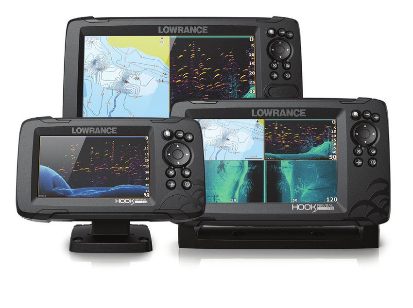
SideScan
About SideScan
SideScan provides a wide coverage in high detail of the seabed to
the sides of your boat.
Ú Note: SideScan is only available on TripleShot models with a
SideScan capable transducer connected.
The SideScan image
The SideScan image can be set up to show left side, right side, or
both left and right side scanning.
1 Speed over ground
2 Depth
3 Temperature
4 Frequency
5 Range scale
Zooming the image
To specify the distance out to the left and right of the center
displayed in the image:
• use the zoom keys
• use the range menu setting
58 SideScan | Hook Reveal Series Operator ManualA change in the range causes a zoom in or out of the image. Using the cursor on the panel By default, the cursor is not shown on the image. To position the cursor on the image, press the Cursor/Waypoint key. Use the Arrow keys to position the cursor. When you position the cursor on the image, the screen pauses, and the cursor information window is activated. The left/right distance from the vessel to the cursor are shown at the cursor position. To remove the cursor and the cursor elements from the panel, press the Cursor/Waypoint key. Viewing history You can view history by panning the image. To pan the image, press the Cursor/Waypoint key to position the cursor on the image. This stops automatic scrolling. • Use the down arrow key to move the cursor to bottom edge of the image. Continue pressing the down arrow key so the image pans down and the historical image is viewed. • Use the up arrow key in the same manner to pan the image back up and display the most current image. • To resume normal scrolling, press the Cursor/Waypoint key to remove the cursor from the image. SideScan | Hook Reveal Series Operator Manual 59
Recording SideScan data
     You can record SideScan data and save the file internally in the unit,
     or onto a memory card as described in "Start recording sonar data" on
     page 48.

     Setting up the SideScan image
     By default the unit is set to Auto mode, and most settings are
     automated. It is recommended that only experienced sonar users
     use the customize settings to further customize the image. Select
     Auto in the menu and change to custom mode to customize image
     settings. Refer to "Custom options" on page 60
     Additional options are available for the Auto and Custom modes.
     Refer to "More options" on page 62.
     When the cursor is active, some options in the menu are replaced
     with cursor mode features. Press the Cursor/Waypoint key to
     remove the cursor from the image and cursor menu options.

     Custom options

     Range
     The range setting determines the water depth and SideScan range
     that is visible on the screen.

     Auto range
     When the range is set to Auto the system automatically sets the
     range depending on the water depth.

     Preset range levels
     You can select between several preset range levels.

     Frequencies
     Two frequencies are supported. 455 kHz provides ideal range and
     image quality in most situations, while 800 kHz is used to provide
     higher detail in shallow water.

     Contrast
     Determines the brightness ratio between light and dark areas of the
     screen.

60   SideScan | Hook Reveal Series Operator Manual
You can also read