Hydrodynamic Analysis for the Morphing Median Fins of Tuna during Yaw Motions
←
→
Page content transcription
If your browser does not render page correctly, please read the page content below
Hindawi
Applied Bionics and Biomechanics
Volume 2021, Article ID 6630839, 15 pages
https://doi.org/10.1155/2021/6630839

Research Article
Hydrodynamic Analysis for the Morphing Median Fins of
Tuna during Yaw Motions

          Xiaohu Li
          Jiangsu University of Science and Technology, Zhenjiang 212003, China

          Correspondence should be addressed to Xiaohu Li; 282105186@qq.com

          Received 24 October 2020; Revised 9 December 2020; Accepted 15 December 2020; Published 4 January 2021

          Academic Editor: Donato Romano

          Copyright © 2021 Xiaohu Li. This is an open access article distributed under the Creative Commons Attribution License, which
          permits unrestricted use, distribution, and reproduction in any medium, provided the original work is properly cited.

          Tuna can change the area and shape of the median fins, including the first dorsal, second dorsal, and anal fins. The morphing
          median fins have the ability of adjusting the hydrodynamic forces, thereby affecting the yaw mobility of tuna to a certain extent.
          In this paper, the hydrodynamic analysis of the median fins under different morphing states is carried out by the numerical
          method, so as to clarify the influence of the erected median fins on the yaw maneuvers. By comparing the two morphing states
          of erected and depressed, it can be concluded that the erected median fins can increase their own hydrodynamic forces during
          the yaw movement. However, the second dorsal and anal fins have limited influence on the yaw maneuverability, and they tend
          to maintain the stability of tuna. The first dorsal fin has more lift increment in the erection state, which can obviously affect the
          hydrodynamic performance of tuna. Moreover, as the median fins are erected, the hydrodynamic forces of the tuna’s body
          increase synchronously due to the interaction between the body and the median fins, which is also very beneficial to the yaw
          motion. This study indicates that tuna can use the morphing median fins to adjust its mobility and stability, which provides a
          new idea for the design of robotic fish.

1. Introduction                                                             Researches showed that tuna median fins have the
                                                                        similar feature as well. In 2017, Pavlov et al. [15] reported
According to the difference of thrust-generation mecha-                  in science that the base of both the second dorsal and anal
nisms, fish swimming can be divided into two types: the                  fins of bluefin and yellowfin tunas is the existing specific
body and/or caudal fin (BCF) mode and the median                         biohydraulic system which can adjust the area and shape
and/or paired fin (MPF) mode [1–4]. The basic function                   of median fins. Median fins are analogous to hydrofoils
of median fins varies greatly between these two modes.                   producing sideways lift force when the fin plane is at an
In BCF mode, median fins are used to maintain body sta-                  angle with the fluid flow direction [5]. Morphing median
bility and prevent fish from swaying and rolling [5–7].                  fins have the ability of regulating the hydrodynamic force.
However, more and more studies have shown that median                   Under the control of lymphatic pressure, the dorsal and
fins of certain fish species which are classified as BCF                   anal fins erect synchronously from cruising behavior with
mode also play an important role in maneuvers. The blue-                prevailing rectilinear motion to searching and feeding behav-
gill sunfish may be one of the most widely studied species.              ior with frequent changes of motion direction. Inspired by
Jayne et al. [8], Drucker and Lauder [9], Tytell and Lauder             this mechanism, Triantafyllou et al. [16] developed a basic
[10], Chadwell et al. [11, 12], Borazjani [13], and Flam-               vehicle and employed morphing median fins to control its
mang and Lauder [14] discussed the features of the soft                 stability and maneuverability. The result indicated that the
dorsal fin of the bluegill sunfish and pointed out that the               biomimetic design of morphing fins for AUV (autonomous
dorsal fin has the function of accelerating the water                    underwater vehicle) can enhance maneuverability to a cer-
around it, increasing hydrodynamic performance and bal-                 tain degree.
ancing overturning moment; therefore, the stability and                     Both tuna and bluegill sunfish can change the area and
maneuverability can be controlled efficiently.                            shape of the median fins. However, their hydrodynamic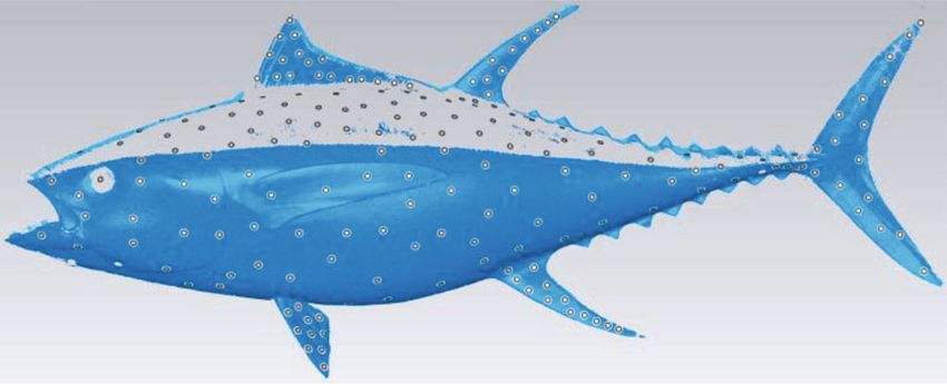
2                                                                                             Applied Bionics and Biomechanics

mechanisms are obviously different. The tuna dorsal fin is an        cussing because it may have an important influence on tuna’s
ensemble with nearly uniform rigidity, while the bluegill’s is     swimming performance.
composed of spiny anterior and soft posterior portions,                The main objective of this paper is to clarify the effect of
which implement high maneuvering mainly by adjusting               erected median fins, including the first dorsal, second dorsal,
the flexible part. Due to the difference in physiological struc-     and anal fins, on the yaw maneuvers of tuna. This study may
ture, tuna generally change the sweep angles of the dorsal and     provide a new idea for the design of a robotic fish, which is to
anal fins, and bluegill can realize oscillation motions of its      adjust its yaw maneuverability and stability by means of
dorsal fin. Thus, the hydrodynamic theory of sunfish’s dorsal        morphing median fins. This article is organized as follows.
fin is not quite suitable for tuna.                                 Section 2 introduces the CAD simulation models of tuna,
    As a long-range and high-performance object for inspir-        the numerical method of hydrodynamic analysis, and the
ing the bionics design [17–19], there are many achievements        configuration of simulation parameters. Section 3 discusses
on hydrodynamic analysis and study of tuna. Wolfgang et al.        the results of hydrodynamic analysis of the median fins
[20] utilized a 3D computational method to describe the            under different morphing states and the interaction between
swimming motions of the bluefin tuna and obtained the visu-         the erected median fins and body. Moreover, the analysis
alization results of the wake structures and the near-body         results are compared and validated with other research data.
hydrodynamics. Takagia et al. [21] estimated the dynamic           Then, the conclusions are shown in Section 4.
properties of bluefin tuna by CFD (computational fluid
dynamics) analysis and pointed out that the glide and              2. Materials and Methods
upward swimming mode of tuna leads to energy saving dur-
ing motion. Feilich and Lauder [22] indicated that the shape       2.1. Tuna Model. Taking a real yellowfin tuna as the original
and stiffness can affect the hydrodynamic performance of a           mold, the physical prototype is obtained by reverse molding
tuna-like tail. Xue et al. [23] carried out a numerical hydrody-   process. The body length (BL) of the tuna prototype is about
namic analysis for a physical prototype imitating the shape of     1.17 m. With laying mark spots around the body and fins, the
tuna based on the Panel method. Then, Xue et al. [24] dis-         tuna prototype is scanned into a point cloud image by using a
cussed the evolvement rule and hydrodynamic effect of fluid          handheld 3D scanner, as shown in Figure 1. The point cloud
field around tuna-like model from starting to cruising. Feng        image is partially missing because the back of the tuna proto-
et al. [4] performed a numerical study on the hydrodynamic         type is black and the laser light cannot be reflected effectively.
of tuna swimming and obtain drag coefficient and vortex dis-         Moreover, there are scattered pieces in the point clouds, so
tribution in C-turn maneuvering. Wang et al. [25] combined         the image needs to be cleaned and reconstructed. It should
experimental and computational methods to study the                be noted that during the reconstruction, the image which is
hydrodynamics of finlets in yellowfin tuna during steady             a half body of the yellowfin tuna needs to form a full-body
swimming. Macias et al. [26] conduct an assessment of the          image with symmetry operation. Based on reasonable simpli-
hydrodynamics of tuna swimming wake flow to identify the            fication, the contours of the dorsal, anal, and caudal fins are
main characteristics related to the propulsion performance         fitted as sine curves by the least square method, while the
by CFD methods. However, in all the above studies, the             contours and sections of the body are polynomial and spline
median fins of tuna are either simplified as a fixed structure        curves. The sine equation of the fitting curves of tuna fins can
or removed for various reasons.                                    be expressed as follows:
    Pavlov et al. [15] constructed CAD models of the Pacific
bluefin tuna with morphing second dorsal and anal fins and                               zn = an ⋅ sin ðbn x + cn Þ:             ð1Þ
carry out hydrodynamic analysis with a CFD program. By
comparing the two morphing states of erected and depressed,             The parameters of the fitting curves are shown in Table 1.
the conclusion is drawn that erected fins increase lift force       The second dorsal and anal fins with different morphing
within a range of yaw angles from 1° to 8°, and the increment      states are obtained by rotating their fitting curves about
of lift force results in raised lift-to-drag (L/D) ratios which    points Od and Oa , respectively. To simplify the CAD model,
may be advantageous at turning maneuvers.                          standard symmetric airfoil profiles (NACA0015) are used for
    This simulation is innovative, but it can be further           all the fin sections based on the measurement data of chord
improved. Tuna is one of the few fish with two dorsal fins.          and thickness [27]. Small deviations from the tuna prototype
The CAD models of Pavlov only have the second dorsal               are made in the body, pectoral and pelvic fins. We believe
and anal fins. In fact, the first dorsal fin can also be regarded     these simplifications and deviations only have a little influ-
as a morphing fin because it can unfold out of groove or fold       ence on overall analysis results because the increment values
in the groove [15]. Due to the relatively larger variation of      of the lift and drag of the median fins among different
area and shape, the hydrodynamic analysis of the first dorsal       morphing states are more important than the absolute values
fin in different morphing states is also necessary. Moreover,        in hydrodynamic analysis.
the flow fields around the two dorsal fins will interact with              During rectilinear cruising, the second dorsal and anal
each other and affect the lift and drag forces, since they are      fins of tuna are both depressed, and the first dorsal fin is
very close and both have the ability of changing shapes. In        folded in the groove. In searching and feeding behavior, the
addition, as the median fins are erected, the distribution of       second dorsal and anal fins erect synchronously, and the first
the flow field around the body may also change. The interac-         dorsal fin unfolds out of the groove. The CAD model of tuna
tion between the body and erected median fins is worth dis-         with two morphing states is shown in Figure 2. According to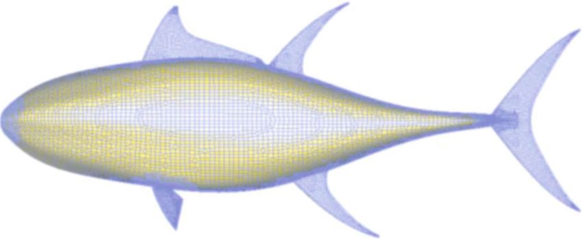
Applied Bionics and Biomechanics 3
(a) (b)
z
3 1
0.2 6
2
0.1 7
Od
O x
0.2 0.4 0.6 0.8
–0.1 Oa 5
–0.2 4
(c)
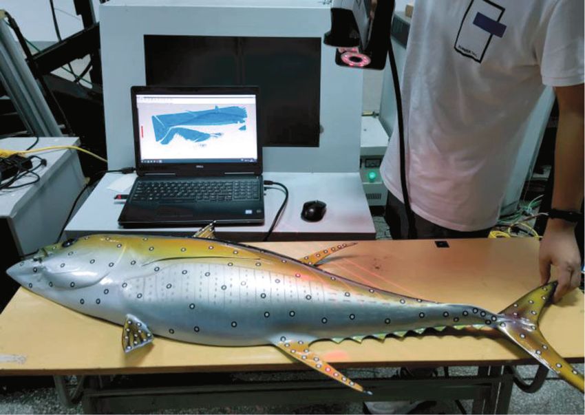
Figure 1: The physical prototype of a yellowfin tuna. (a) Scanning the physical prototype with a 3D scanner; (b) the point cloud image; (c) the
fitting curves of the tuna model.
Table 1: The fitting curve parameters. constant under this condition. However, the C L and CD
of tuna median fins are different with different morphing
n an bn cn x states due to the change of shape, area, and even rigidity.
1 219.4 0.004698 10.51 0:54 ≤ x ≤ 0:72 Thus, it is difficult to derive the hydrodynamic expressions
Second dorsal fin of tuna median fins accurately.
2 218.5 0.006867 15.16 0:62 ≤ x ≤ 0:72
First dorsal fin 3 241.1 0.01156 9.665 0:29 ≤ x ≤ 0:36
C L ρSν2 ð2Þ
4 213.3 0.004391 7.40 0:59 ≤ x ≤ 0:78 FL = ,
Anal fin 2
5 213.8 0.005812 18.74 0:67 ≤ x ≤ 0:78
6 194.4 0.00666 12.25 0:99 ≤ x ≤ 1:17 C D ρSν2 ð3Þ
Caudal fin FD = ,
7 202.8 0.009863 27.17 1:08 ≤ x ≤ 1:17 2
where CL and C D are the lift and drag coefficients, respec-
tively, ρ is the density of the fluid, S is the projected area
the measurement data of Pavlov et al. [15], the sweep angle of of the median fin, and v is the swimming velocity of the
the first dorsal fin, second dorsal fin, and anal fin in the erec- fish.
tion state is set to 35°, 58°, and 61°, respectively. In the depres- In this paper, a numerical method is applied to the
sion state, the sweep angle is set to 0°, 76°, and 79°, hydrodynamic analysis for the tuna and its morphing
respectively. median fins. The flow field of tuna swimming is simulated
with the commercial ISIS-CFD flow solver which adopts
2.2. Numerical Method. As the fish swims, the median fins the incompressible unsteady Reynolds-averaged Navier-
are subjected to the reaction force of the surrounding Stokes equations. This solver discretizes the transport
fluid. In the previous studies, the median fin is usually equations of tuna swimming by the finite volume method.
simplified as a fixed rigid body, and the dynamic theory The velocity field and pressure field of tuna swimming are
of the wing is used to analyze the lift force F L and drag obtained from the momentum conservation equations and
force F D [1, 28, 29], as shown in equations (2) and (3). the mass conservation continuity equation. Because of the
The forces F L and F D are easily obtained by measuring turbulence phenomenon in fish swimming, additional
the lift coefficient C L and drag coefficient C D which are transport equations are needed to model the turbulence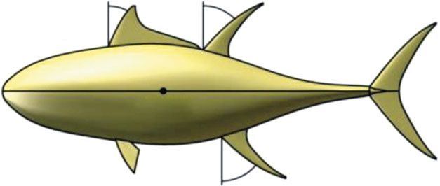
4 Applied Bionics and Biomechanics
35° 58° 76°
COM
COM
79°
61°
(a) (b)
Figure 2: The morphing states of the median fins. (a) All median fins are erected. (b) All median fins are depressed.
variables which can be discretized and solved in a form F x ), which can be computed by integrating the pressure
similar to the momentum equations [30–33]. This flow and viscous forces acting on the fin surface S [4, 36].
solver has several near-wall turbulence models, such as 2ð 3
one-equation Spalart-Allmaras model, two-equation k-ε
" # τ I − pI ⋅ ndS
models and k-ω models, which can be employed in a vari- Fx 6 1j j 1 7
=6 7,
S
ety of fish swimming cases. F= 6ð 7 ð7Þ
Fy 4 5
Generally, tuna swims in the ocean which is regarded as τ2j I j − pI 2 ⋅ ndS
an incompressible viscous monofluid. If only yaw or turning S
motions are taken into account, the gravity of tuna in Z direc-
tion is assumed to be offset by its buoyancy. Thus, the gov- where p is the pressure vector, I j is the jth component of
erning equations of tuna swimming can be simplified as direction vector, n is the unit normal vector, and τij is the vis-
follows: cous stress tensor.
ð ð The yaw moment M z with respect to the center of mass
∂ (COM) can be calculated by the following formula:
ρdV + ρðU − U d Þ ⋅ ndS = 0,
∂t V S ð
ð ð ð
∂ Mz = r × τ1j I j − pI 1 ⋅ n + r × τ2j I j − pI 2 ⋅ n dS, ð8Þ
ρU i dV + ρU i ðU − U d Þ ⋅ ndS = τij I j − pI i ⋅ ndS, S
∂t V S S
ð4Þ where r is the position vector from the tuna’s COM.
The numerical algorithm for the flow field of tuna swim-
where V is the domain of interest, or control volume, ming is described as follows:
bounded by the closed surface S moving at the velocity U d
with a unit normal vector n directed outward; ρ is the density (1) Define the yaw motion law of the tuna; then the U R
of the control volume; U and p represent the velocity and and U T is imposed
pressure fields, respectively; and τij are the components of (2) Update the tuna position according to the motion law
the viscous stress tensor, whereas I i and I j are direction at step k
vectors.
The grid of the flow field around the tuna moves synchro- (3) Solve the governing equation (4) and the space con-
nously as the tuna swims, so the space conservation law must servation law (5) with the no-slip boundary condition
also be satisfied: (6) to obtain the flow field distribution around the
tuna model [4]
ð ð
∂ (4) Calculate the hydrodynamic force F and yaw
dV − U d ⋅ ndS = 0: ð5Þ
∂t V S moment M z acting on the median fins according to
formulas (7) and (8)
To solve the governing equations in this viscous flow, the
(5) Return to (2) at the next step k + 1
no-slip boundary condition is imposed on the tuna models
[4]: 2.3. Parameter Configuration. During yaw or turning maneu-
vers, the exposed median fins can generate hydrodynamic
U + = U = U T + U R, ð6Þ forces, and the variations of their sweep angles can directly
affect the lift and drag, thereby changing mobility. We define
where U is the velocity vector of the tuna. If the tuna is sim- the yaw motion as a uniform translation movement superim-
plified as a rigid body, the velocity U only can be decomposed posed on a rotational movement. The yaw motion law of the
into two components [34, 35]: the translation velocity U T tuna can be expressed as follows:
and the rotational velocity U R . (
For yaw maneuvers, the tuna only swims in the X-Y U Tx = ν,
plane. The fluid force F of the median fin is regarded as the U= ð9Þ
resultant force of two components F L (or F y ) and F D (or U Rz = ω ⋅ r,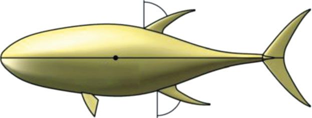
Applied Bionics and Biomechanics                                                                                                            5

                                   (a)                                                        (b)

Figure 3: The unstructured hexahedral meshes of the flow field and tuna model: (a) the volume mesh of the flow field and (b) the surface grid
of the tuna model.

                                           Table 2: The simulation parameter configuration.

Parameter                                                                                                              Value
Domain size                                                                                                         6×4×4m
Turbulence model                                                                                                      k-ω SST
Yaw angular velocity                                                                                        ω = 0:01, 0.5, 1.0, 1.5 rad/s
Translation velocity                                                                                                v = 10 m/s
Time step                                                                                                Δt = 5:0e-2, 1.0e-3, 5.0e-4, 3.3e-4s
Convergence criteria                                                                                                  2 orders
Maximum number of iterations                                                                                             20
                                                          Erection                                                    1744610
Total number of cells
                                                         Depression                                                   1614307

where v is the translation velocity in X direction, r is the posi-    above parameter settings, the total cells of the domains are
tion vector from the COM, and ω is the yaw angular velocity           over 1.74 and 1.61 million in the erection and depression
around Z axis.                                                        states, respectively.
    The computational domain of the flow field is a cuboid                   The main simulation configuration is shown in Table 2.
with a size of 6 × 4 × 4 m. The tuna model yaws around its            The k-ω SST turbulence model, which combines several
COM according to the specified motion law in the domain.               desirable elements of original k-ω and k-ε models, is the rec-
The unstructured hexahedral meshes are generated based                ommended model for all basic hydrodynamic computations
on HEXPRESS™, as shown in Figure 3. The mesh size of                  in FINE™/Marine [33]. The two major features of this model
the median fins is less than 3 mm, and that of the tuna body           are a zonal blending of model coefficients and a limitation on
is about 6 mm. The box refinement is applied to refine the              the growth of the eddy viscosity in rapidly strained flows. It is
cells around the tuna model. When doing computations                  suitable for the numerical analysis of tuna swimming. The
including viscosity, the boundary layer near the tuna model           translation velocity of the tuna model is set as v = 10 m/s
contains high gradients. To properly capture these high gra-          because the swimming speed of tuna is generally
dients, it is important to have a sufficient number of grid             30~50 km/h. The yaw angular velocity is estimated empiri-
points inside the boundary layer. As no-slip boundary condi-          cally to be 0.5~1.5 rad/s. Moreover, a simulation case with
tion is imposed on the tuna model, the suggested Y + value is         an angular velocity of 0.01 rad/s is also calculated. Due to
below 1 [33]. According to the Reynolds number and Y +                the relatively small angular velocity, it can be used to analyze
value, the first layer thickness of the boundary layer is esti-        the hydrodynamics of the median fins without high speed
mated as 0.003~0.005 mm, and the number of layers is                  yaw maneuvers. The case is called the quasistatic yaw motion
approximately 21~26 with the stretching ratio of 1.3. After           in this paper. Other parameters, such as maximum number
automatic optimization by the mesh generator under the                of iterations, convergence criteria, initial condition, and fluid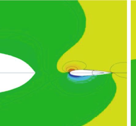
6                                                                                                                                                       Applied Bionics and Biomechanics

                                     60                                                                       240

                                     48
                                                                                                              180

                          Drag (N)
                                     36

                                                                                                  Lift (N)
                                                                                                              120
                                     24

                                                                                                                  60
                                     12

                                      0                                                                            0
                                          0   4       8                12       16       20                            0        4          8           12   16   20

                                                            θ (°)                                                                              θ (°)

                                              AF-E                                                                              AF-E
                                              AF-D                                                                              AF-D
                                                     (a)                                                                                 (b)
                                                                       6

                                                                       5

                                                                       4
                                                           L/D ratio

                                                                       3

                                                                       2

                                                                       1

                                                                       0
                                                                            0        4        8              12            16       20

                                                                                                  θ (°)

                                                                                 AF-E
                                                                                 AF-D
                                                                                          (c)

Figure 4: The drag, lift, and L/D ratio of the anal fin (AF) in the erection and depression states under the quasi-static yaw motion (ω = 0:01
rad/s): (a) the drag of the anal fin; (b) the lift of the anal fin; (c) the L/D ratio of the anal fin. Note: AF-E (or AF-D) represents the erection (or
depression) state of the anal fin.

properties, are set by default or suggested values in FINE™/-                                       the yaw angle is about 7°~10°, then decreases gradually.
Marine. These default values satisfy the simulation require-                                        When the yaw angle is below 3°, the L/D ratio of the erection
ments in most cases, including the hydrodynamic analysis                                            state is close to that of the depression state. Then, the L/D
of tuna swimming.                                                                                   ratio of the erection state is relatively higher. At the yaw angle
                                                                                                    of 8.9°, the maximum value of the L/D ratio in the erection
3. Results and Discussion                                                                           and depression state is 5.76 and 5.3, respectively. It means
                                                                                                    that the erected anal fin increases its L/D ratio by approxi-
3.1. Hydrodynamic Analysis under Quasistatic Yaw Motion.                                            mately 8.7%.
The drag, lift, and L/D ratio of the anal fin (AF) in the erec-                                          Figure 5 shows the drag, lift, and L/D ratio of the two dor-
tion and depression states under the quasistatic yaw motion                                         sal fins in the two morphing states under the quasistatic yaw
(ω = 0:01 rad/s) are obtained by CFD analysis, as shown in                                          motion (ω = 0:01 rad/s). On the whole, the hydrodynamic
Figure 4. It can be seen that both lift and drag forces increase                                    trend of the two dorsal fins is similar to that of the anal fin.
with the increase of the yaw angle (θ) in the two morphing                                          The lift and drag of the two dorsal fins increase with the
states. And both the lift and drag force of the erection state                                      increase of yaw angle as well, and the L/D ratio also grows
are greater than those of the depression state within a range                                       at first and then reduces gradually. However, their hydrody-
of yaw angles from 0.3° to 20°. This indicates that the erected                                     namic forces still have some different features. It should be
anal fin can enhance its hydrodynamic forces. In the early                                           noted that the first dorsal (FD) fin is completely folded into
stage of yaw motion, the drag changes slowly, while the lift                                        the groove in the depression state, so its lift and drag are
grows fast. But as the yaw angle increases, the drag rises more                                     regarded as zero. At this moment, only the second dorsal
and more quickly, while the lift rises slowly. As a result, the                                     (SD) fin generates hydrodynamic forces. Its L/D ratio reaches
L/D ratio improves rapidly at first and reaches the peak when                                        the maximum of 11.7 at the yaw angle of 5.8°. Compared with
Applied Bionics and Biomechanics                                                                                                                                       7

                                      150                                                                      400

                                      120                                                                      320

                                       90                                                                      240

                           Drag (N)

                                                                                                    Lift (N)
                                       60                                                                      160

                                       30                                                                       80

                                        0                                                                           0
                                            0   4        8               12       16       20                           0        4          8           12   16   20

                                                                θ (°)                                                                           θ (°)

                                                FD-E                                                                             FD-E
                                                SD-E                                                                             SD-E
                                                SD-D                                                                             SD-D
                                                       (a)                                                                                (b)
                                                                         12

                                                                         9
                                                             L/D ratio

                                                                         6

                                                                         3

                                                                         0
                                                                              0        4        8              12           16       20

                                                                                                    θ (°)
                                                                                   FD-E
                                                                                   SD-E
                                                                                   SD-D
                                                                                            (c)

Figure 5: The drag, lift, and L/D ratio of the first dorsal (FD) and second dorsal (SD) fin in the erection and depression states under the quasi-
static yaw motion (ω = 0:01 rad/s): (a) the drag of the two dorsal fins; (b) the lift of the two dorsal fins; (c) the L/D ratio of the two dorsal fins.
Note: FD-E represents the erection state of the first dorsal fin; SD-E (or SD-D) represents the erection (or depression) state of the second
dorsal fin.

the anal fin, the second dorsal fin is more active in the depres-                                           However, the erection of the first dorsal fin makes up for
sion state.                                                                                           the weakening of the second dorsal fin. The drag and lift of
     With the erection of the first dorsal fin, the hydrody-                                            the first dorsal fin are much larger than those of the second
namic performance of the second dorsal fin has changed.                                                dorsal and anal fins. Its L/D ratio becomes the maximum of
Its lift reduces a lot, while the drag decreases a little. Conse-                                     11.2 at the yaw angle of 6.4°, which is also higher than the
quently, the L/D ratio of the second dorsal fin diminishes                                             other two fins. It shows that the erected first dorsal fin plays
by about 50% from the peak. In a word, the effect of the sec-                                          a dominant role among the three median fins. This result is
ond dorsal fin is weakened in the erection state. This is sim-                                         easy to understand. In the erection state, the area of the sec-
ilar to the phenomenon in a marathon that the runners in                                              ond dorsal and anal fin is about 57% and 55.6% of that of the
front can reduce the wind drag of the runners behind under                                            first dorsal fin, respectively. The area increment of the second
certain conditions. Since the first dorsal fin is not far in front                                      dorsal and anal fin is about 15% and 15.7%, while that of the
of the second dorsal fin, the flow field of the first dorsal fin                                           first dorsal fin is 100%. The absolute area of the two median
can also affect the hydrodynamic performance of the second                                             fins, as well as the incremental area, is much smaller than that
dorsal fin. When the first dorsal fin is erected, the flow fields                                          of the first dorsal fin, resulting in less hydrodynamic forces.
of the two dorsal fins are fused together partially. The low-                                              Figure 6 is the yaw moment of all the median fins in the
pressure area behind the first dorsal fin extends to the second                                         erection and depression states under the quasistatic motion
dorsal fin, reducing the pressure difference between the two                                            (ω = 0:01 rad/s). It can be seen that the yaw moments of the
sides of the second dorsal fin, which leads to the decrease of                                         second dorsal and anal fins are negative in the two morphing
its lift and L/D ratio.                                                                               states. This indicates that they have the ability of preventing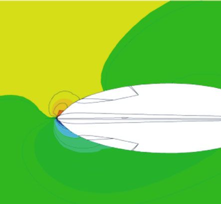
8 Applied Bionics and Biomechanics
40 10
0
20 –10
Moment (Nm)
Moment (Nm)
–20
0
–30
–40
–20
–50
–40 –60
–70
0 4 8 12 16 20 0 4 8 12 16 20
θ (°) θ (°)
AF-E AF-D E
FD-E SD-D D
SD-E
(a) (b)
Figure 6: The yaw moment of the median fins in the erection and depression states under the quasi-static yaw motion (ω = 0:01 rad/s): (a) the
respective moment of all the median fins; (b) the resultant moment of all the median fins.
50%
of yaw motion and behind the aerodynamic center. Com-
40% pared with the second dorsal and anal fins, the first dorsal
fin is the one that can improve yaw mobility.
When the yaw angle θ is below 4°, the resultant moment
30% of all the median fins in the erection state is a very small
F/B ratio
value. It means that within the yaw angles of 0°~4°, the
20% median fins as a whole are nearly in a neutral position, which
influence neither maneuverability nor stability. Tuna is good
10%
at long-distance cruising and has a relatively rigid body and
large turning radius compared with other fish [15]. This
may indicate that turning or yaw motions are usually
0 achieved at a relatively small yaw angle. The neutrality of
0 4 8 12 16 20
the median fins at small yaw angles may be beneficial for tuna
θ (°) to control swimming behaviors, making it easier to trade-off
between maneuverability and stability.
E-lift D-lift
The hydrodynamic analysis of each of the three median
E-drag D-drag
fins in the two morphing states has been performed above.
Figure 7: The F/B ratio in the erection and depression states under More importantly, to what extent can the hydrodynamic
the quasistatic yaw motion. force of the median fins affect the swimming performance
of tuna. Without considering the pectoral, pelvic, and caudal
fins, we define the fin-to-body (F/B) ratio as the ratio of the
yaw maneuverability and promoting stability. But the first sum of the hydrodynamic forces of all three median fins to
dorsal fin does have the function of improving mobility. In the hydrodynamic force of tuna’s body. As shown in
the state of erection, its yaw moment is positive. Although Figure 7, within a range of yaw angles from 0.3° to 20°, the
the hydrodynamic forces of the second dorsal and anal fins F/B lift ratio is about 16.9%~25.7% and 29.9%~45.7% in
are very small, their moments are relatively large due to the the depression and erection states, respectively. The F/B drag
longer distance from the COM. Most of the time, the positive ratio is about 7.5%~17.1% and 22.1%~38.3%, respectively. It
moment produced by the first dorsal fin cannot completely can be seen that due to the involvement of the first dorsal fin,
offset the reverse moments of the second dorsal and anal fins. the F/B ratio increases greatly in the erection state, and the
From Figure 2, it can be seen that the first dorsal fin is hydrodynamic forces of the three erected median fins have
located in front of the COM, and the second dorsal and anal reached such a level that it cannot be ignored. Moreover,
fins are located behind the COM, which directly results in the when the yaw angle is small, the curve of F/B lift ratio is at
opposite yaw moments and different hydrodynamic perfor- a relatively high position, while that of the F/B drag ratio is
mance. The above analysis results are in agreement with the relatively low. It means that the median fins have greater
opinion of Triantafyllou et al. [16] that median fins can influence on the yaw motion of tuna at the small yaw angles.
increase the yaw rate only if it is placed in front of the center As discussed above, this may be an optimization of the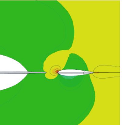
Applied Bionics and Biomechanics                                                                                                                                         9

                                   900                                                                      2500

                                   750
                                                                                                            2000
                                   600

                        Drag (N)

                                                                                                 Lift (N)
                                                                                                            1500
                                   450
                                                                                                            1000
                                   300

                                   150                                                                       500

                                     0                                                                           0
                                         0   4       8               12      16       20                             0    4          8           12   16   20

                                                            θ (°)                                                                        θ (°)
                                             B-E                                                                          B-E
                                             B-D                                                                          B-D
                                                   (a)                                                                             (b)
                                                                     6

                                                                     5

                                                                     4
                                                         L/D ratio

                                                                     3

                                                                     2

                                                                     1

                                                                     0
                                                                         0        4        8                12       16       20

                                                                                                 θ (°)

                                                                             B-E
                                                                             B-D
                                                                                           (c)

Figure 8: The drag, lift, and L/D ratio of the tuna body in the erection and depression states under the quasi-static yaw motion (ω = 0:01
 rad/s): (a) the drag of the body; (b) the lift of the body; (c) the L/D ratio of the body. Note: B-E (or B-D) represents the hydrodynamic
force of the body (B) when all median fins are erected (or depressed).

                                                                                                                                                                 20000

                                                                                                                                                                     0

                                                                                                                                                                –20000

                                                                                                                                                                –40000

                                                                                                                                                                –60000

                                     (a)                                                                                      (b)

Figure 9: The pressure contours of the tuna body on the cut plane of Z = 0:12 m at a yaw angle of 9.5° in the depression and erection states,
respectively: (a) the pressure contour of the body when all the medians are depressed; (b) the pressure contour of the body when all the
medians are erected. Note: the white ellipses are the cut sections of the body and second dorsal fin, respectively.
10 Applied Bionics and Biomechanics
600 Since the tuna’s body is exactly the same in the two morphing
states, we believe that the body-fin interaction is responsible
500 for the raised L/D ratio. This is in agreement with the view-
Lift (Drag) increment (N)
point of Liu et al. [37]. By comparing the body-median-fin
400
model and the body-only model, they have drawn the con-
300 clusion that the body-fin interaction improves thrust in
swimming fishes. It is slightly different from this paper. Their
200 conclusion focuses on the influence of the presence or
absence of the median fins on the hydrodynamic forces,
100 while we are concerned about the effect of the morphing
states of the median fins. After a long period of evolution,
0
tuna has become a complex and sophisticated system. Any
–100 change in its morphological structure may cause obvious
0 4 8 12 16 20 changes in the overall performance. The morphing states of
the median fins have an important influence on the body’s
θ (°) hydrodynamic forces, thus further affecting the swimming
B-lift B-drag performance of tuna.
FD-lift FD-drag One reliable explanation about the body-fin interaction is
SD-lift SD-drag that the pressure distribution around the body changes as the
AF-lift AF-drag median fins is erected. Figure 9 is the pressure contours of the
body in the two morphing states at the yaw angle of 9.5°. The
Figure 10: The lift and drag increments in the erection state of the coordinate of the cut plane is z = 0:12 m, which is closer to
body (B), first dorsal (FD), second dorsal (SD), and anal fins (AF)
the dorsal fins. When the first dorsal fin is folded into the
under the quasistatic yaw motion (ω = 0:01 rad/s).
groove, the pressure field around the body on the cut plane
is even. With the erection of the median fins, the pressure
40 of the front edge of the body’s upstream surface increases,
while the pressure on the downstream surface decreases,
thereby enlarging the pressure difference between the two
Moment increment (Nm)
sides of the body. This is the direct cause of the increase in
20 the lift and L/D ratio. Another phenomenon also can be seen
from Figure 9. Compared with the erection state, the flow
field around the second dorsal fin appears obvious high-
pressure and low-pressure areas in the depression state. This
0 further confirms that the second dorsal fin has less hydrody-
namic forces in the erection state.
Figure 10 is the lift and drag increments in the erection
state. It can be seen that the lift increments of the second dor-
–20 sal and anal fins are relatively small. It seems that changes in
0 4 8 12 16 20 their own hydrodynamic forces can hardly have a significant
impact on tuna’s mobility. When the yaw angle is small, the
θ (°) lift increment of the first dorsal fin is the largest, followed
B SD by the body. They work together to enhance the swimming
FD AF performance of the tuna. As the yaw angle increases, the lift
increment of the body is even greater, and its drag increment
Figure 11: The moment increments in the erection state of the body is relatively less than that of the first dorsal fin. Gradually, the
(B), first dorsal (FD), second dorsal (SD), and anal fins (AF) under body has more efficient hydrodynamic performance. It
the quasistatic yaw motion (ω = 0:01 rad/s). implies that the body-fin interaction, rather than the median
fins themselves, may be one of the important reasons for
median fins for swimming control at small inclination yaw improving mobility in the erection state.
motions. As shown in Figure 11, from the perspective of moment
increment, the first dorsal fin and the body still play an
3.2. The Body-Fin Interaction. It needs to be noted that the important role in promoting yaw maneuvers. Their moment
erection of the median fins affects not only themselves but increments are usually larger than those of the second dorsal
also the hydrodynamics of the tuna’s body. As shown in and anal fins. As mentioned above, the moments of the sec-
Figure 8, the lift and drag force of the body also increase, ond dorsal and anal fins are negative. In the erection state,
when all the median fins are erected. And the maximum due to the decrease of hydrodynamic forces of the second
value of the L/D ratio of the body rises from 4.3 to 5.1 at dorsal fin, its reverse moment reduces, which is equivalent
the yaw angle of 9.3°. An increase of 18.6% in the L/D ratio to an increase in the positive moment. But the anal fin pro-
is very beneficial for tuna in searching and feeding behaviors. duces more reverse moment, which further inhibits the yawApplied Bionics and Biomechanics 11
16
16
12
12
L/D ratio
L/D ratio
8 8
4 4
0
0
0 4 8 12 16 20
0 4 8 12 16 20
θ (°)
θ (°)
E-1.5 D-1.5
E-1.5 D-1.5
E-1.0 D-1.0
E-1.0 D-1.0
E-0.5 D-0.5
E-0.5 D-0.5
(a) (b)
80
40
Lift increment
0
–40
–80
0 4 8 12 16 20
θ (°)
AF-0.5 SD-0.5
AF-1.0 SD-1.0
AF-1.5 SD-1.5
(c)
Figure 12: The L/D ratios and lift increment of the anal and second dorsal fins in the two morphing states with the yaw angular velocity of
ω = 0:5 rad/s, 1 rad/s, and 1.5 rad/s, respectively: (a) the L/D ratio of the anal fin; (b) the L/D ratio of the second dorsal fin; (c) the lift increment
of the anal and second dorsal fin.
motion. The sum of their moment increments is very small and 1.5 rad/s, the corresponding maximum value of the L/D
within the yaw angles of 0°~9°. It indicates that the erection ratio in the erection state is 7.1, 10.0, and 14.7. And in the
of the second dorsal and anal fins has limited effect on yaw depression state, it is 7.6, 13.1, and 17.9, respectively. Obvi-
maneuvers when the yaw angle is below 9°. ously, this shows two points. One is that the L/D ratio
increases with the increase of the yaw speed under the same
3.3. Hydrodynamic Analysis during Yaw Maneuvers. Differ- morphing state. The other is that the L/D ratio of the erection
ent from the quasistatic motion, the yaw maneuvers have a state is smaller than that of the depression state at the same
higher angular velocity. With the increase of the yaw speed, speed. Similar to the anal fin, the L/D ratio of the second dor-
the hydrodynamic characteristics of the median fins change sal fin in the erection state is also reduced, and the reduction
in some aspects. As shown in Figure 12, the L/D ratios of is more significant. The maximum L/D ratio of second dorsal
the anal fin rise rapidly to the maximum values when the fin in the depression state can reach 12.8, 13.9, and 15.4, with
yaw angles are about 2.5°~5.5° in the two morphing states. the corresponding yaw speed of 0.5 rad/s, 1.0 rad/s, and
Compared with the quasistatic condition, the peak values of 1.5 rad/s. But in the erection state, it is reduced to 6.6, 7.7,
L/D ratio appear earlier. This is in line with the characteristic and 9.8, respectively. Due to the negative effect of the first
of tuna’s small-inclination axial movement and is more con- dorsal fin, its L/D ratios decrease by about 36~48%. It can
ducive to the quick intervention of the median fins in the yaw be seen that the erection of the anal and second dorsal fins
maneuvers. When the angular speed is 0.5 rad/s, 1.0 rad/s, only raises the lifts and drags, not the L/D ratios. In other12 Applied Bionics and Biomechanics
12
5
9 4
L/D ratio
L/D ratio
3
6
2
3 1
0
0
0 4 8 12 16 20
0 4 8 12 16 20
θ (°)
θ (°)
E-1.5 D-1.5
E-1.5
E-1.0 D-1.0
E-1.0
E-0.5 D-0.5
E-0.5
(a) (b)
600
500
400
Lift increment
300
200
100
0
0 4 8 12 16 20
θ (°)
B-0.5 FD-0.5
B-1.0 FD-1.0
B-1.5 FD-1.5
(c)
Figure 13: The L/D ratio and lift increment of the first dorsal fin and the body in the two morphing states with the yaw angular velocity of
ω = 0:5 rad/s, 1 rad/s, and 1.5 rad/s: (a) the L/D ratio of the first dorsal fin; (b) the L/D ratio of the body; (c) the lift increment of the first dorsal
fin and the body.
words, the drag force increases more than the lift force in the second dorsal and anal fins may be more inclined to improve
erection state. It is not beneficial to the improvement of the stability of the tuna rather than its yaw maneuverability.
hydrodynamic performance. As shown in Figure 13, the maximum L/D ratios of the
Moreover, the lift increment of the erected anal fin is a first dorsal fin decrease slightly with the increase of the yaw
positive value during the yaw maneuvers, while that of the speed. When the velocity is 0.5 rad/s, 1.0 rad/s, and 1.5 rad/s,
erected second dorsal fin is a negative value. The sum of their the corresponding value is 9.7, 10.2, and 10.7, respectively.
lift increments is nearly zero, so the effects on tuna’s mobility The L/D ratio of the body is usually larger in the erection
almost cancel each other out. Similarly, the moment incre- state than that in the depression state at any given angular
ments also offset each other. From the perspective of lift velocity. And the maximum values of L/D ratio increase by
and moment increment, the erection of these two median about 10~18% in the erection state. No matter which state
fins does not directly improve the tuna’s mobility during the body is in, the L/D ratio curves converge at an intersec-
the yaw maneuvers. This is consistent with the previous con- tion point. The yaw angle of the point is 5.9° in the erection
clusion. The median fins of a tuna are analogous to the state, while it is 7.3° in the depression state. When the yaw
morphing wing of an aircraft. According to the wing theory, angle is less than the point, the L/D ratios increase with the
the morphing wing can optimize the flight performance of increase of the yaw speed; otherwise, they decrease with the
the aircraft at high and low speeds. The erected wing is increase of the angular velocity.
mainly used to improve stability at low speed rather than The lift increments of the first dorsal fin and body do not
maneuverability. By the same principle, the erection of the vary much with different yaw speeds when the yaw angles areApplied Bionics and Biomechanics 13
5 within a range of yaw angles from 4.5° to 7.5°, then decrease
gradually to about 2~3.5. Basically, the trend is also consis-
tent with the test data of the morphing aquatic micro air
4
vehicle [38], which can change sweep the angle of its wing
during the flight. This shows that the simulation results of
L/D ratio of body
3 this paper are credible to a certain extent.
Due to the differences of CAD models, the absolute values
of L/D ratios are different between current results and Pavlov’s
2
data. The model in this paper is based on a yellowfin tuna and
uses NACA0015 airfoil as the cross-section of all the fins,
1 while the model of Pavlov is constructed without some details
of a bluefin tuna morphology, including the first dorsal and
pelvic fins [15]. As mentioned above, the presence of the first
0
dorsal fin weakens the L/D ratio of the second dorsal fin,
0 4 8 12 16 20
which causes an obvious difference in the erection state. In
θ (°) addition, the simulation in this paper is carried out at the
yaw speed of 0.01 rad/s, while the Pavlov’s data are obtained
Coarse
under static conditions. This is also one of the reasons for
Medium
the difference. Under different modeling and computational
Fine
methods, it is a common phenomenon that there are some
Figure 14: The L/D ratio of the body with different grids (ω = 0:01 discrepancies in the absolute values of simulation results.
rad/s; depression state). However, relative values are the focus of this paper. What
we care about is the lift and L/D increments between the
below 9°. They are much larger than the lift increments of the erection and depression states. In fact, the increment values
second dorsal and anal fins, which are enough to affect the of L/D ratios are close to each other. The L/D increment of
swimming performance of tuna. These further confirm that the erected anal fin in this paper is about 8.7%, and Pav-
the first dorsal fin and the body-fin interaction are the two lov’s result is about 11%. This is also similar to the data
main ways to improve the hydrodynamic forces in the erec- of Siddall et al. [38]. And we all came to the same conclu-
tion state. sion that the erected median fins could increase their own
Tuna has two dorsal fins, and their functions are different lifts to a certain extent. This further verifies the simulation
due to the different positions. The first dorsal fin is located in results in this paper. But it should also be emphasized that
front of the COM, and its hydrodynamic forces can provide our views do not coincide in some aspects. Pavlov et al.
positive moment for yaw motions, while the second dorsal pointed out that the erected second dorsal and anal fins
fin is opposite. This may provide a new bionic idea for the may facilitate turning maneuvers, but the analysis result of
design of robotic fish. Most of the existing robotic fish that this paper shows that only the first dorsal fin can improve
mimic the BCF swimming mode have only one fixed dorsal maneuverability.
fin. Inspired by this mechanism, we can use two morphing
dorsal fins to balance the maneuverability and stability of the
robotic fish by adjusting their erection or depression states. 4. Conclusion
3.4. Comparative Verification. A mesh independence study is On the basis of scanning and measuring the physical model
conducted by using three different sets of grids in the depres- of real yellowfin tuna, the CAD simulation models with two
sion state, which have about 1.24 (coarse), 1.61 (medium), morphing states of the median fins are constructed in this
and 2.56 (fine) million cells, respectively. Figure 14 is the L/ paper. The hydrodynamic analyses of the median fins under
D ratio of the body with different grids at the same yaw speed different morphing states are carried out by numerical
of 0.01 rad/s. It can be seen that the three sets of simulation method, to clarify the influence of the median fins on the
data are very close to each other. Taking the results of the fine yaw motion of tuna. Through the discussion of the simula-
grid as reference, the maximum error of the coarse grid and tion results, the following conclusions can be drawn:
medium grid is about 2.51% and 2.1% within a range of
yaw angles from 0.5° to 20°, respectively, and the mean error (1) The erection of the median fins can improve the
is about 0.96% and 0.4%. The accuracy of the medium mesh hydrodynamic forces. The L/D ratio of the erected
used in this paper is acceptable and does not affect the cor- anal fin increased by a maximum of 8.7%. Due to
rectness of the conclusions above. It shows that these simula- the negative impact of the first dorsal fin, the hydro-
tions are mesh independent. dynamics of the second dorsal fin is reduced in the
To verify the reliability of current results, it is compared erection state. The second dorsal and anal fins are
with the simulation data of Pavlov et al., as shown in located behind the COM and produce a reverse yaw
Figure 15. On the whole, the trend of L/D ratio curves is sim- moment. Their resultant lift and moment change a
ilar. The L/D ratios of the second dorsal fin increase quickly little between the two morphing states, so the effect
when the yaw angle is small and reach the maximum values on the yaw mobility of tuna is limited14 Applied Bionics and Biomechanics
12 12
10 10
8 8
L/D ratio
L/D ratio
6 6
4 4
2 2
0 0
0 4 8 12 16 20 0 4 8 12 16 20
θ (°) θ (°)
SD-E (Pavlov) SD-E AF-E (Pavlov) AF-E
SD-D (Pavlov) SD-D AF-D (Pavlov) AF-D
(a) (b)
Figure 15: Comparison of current results with the simulation data of Pavlov: (a) the L/D ratio of the second dorsal fin; (b) the L/D ratio of the
anal fin.
(2) Because of the larger area increment of the first dorsal Conflicts of Interest
fin, its hydrodynamic increment in the erection state
is much larger than that of the second dorsal fin and The author declares that there is no conflict of interest
anal fin. And the first dorsal fin located in front of the regarding the publication of this paper.
COM can generate positive yaw moment, which is
beneficial to enhance the yaw performance of tuna.
Thus, it is believed that among the three median fins, Acknowledgments
the erected first dorsal fin plays a leading role in
improving yaw mobility This work was supported by the National Natural Science
Foundation of China under Grant 51805512.
(3) In addition to raising their own hydrodynamic
forces, the erection of the median fins also affects
the hydrodynamics of the body. When all median References
fins are erected, the distribution of the flow field
around the body changes, increasing its lift force [1] M. Sfakiotakis, D. M. Lane, and J. B. C. Davies, “Review of fish
and yaw moment. This body-fin interaction also has swimming modes for aquatic locomotion,” IEEE Journal of
an important effect on the yaw maneuvers, further Oceanic Engineering, vol. 24, no. 2, pp. 237–252, 1999.
improving the hydrodynamic performance of the [2] K. E. Korsmeyer, J. F. Steffensen, and J. Herskin, “Energetics of
tuna. This indicates that compared with the second median and paired fin swimming, body and caudal fin swim-
dorsal fin and anal fin, the erected first dorsal fin ming, and gait transition in parrotfish (Scarus schlegeli) and
and body-fin interaction have more significant effects triggerfish (Rhinecanthus aculeatus),” The Journal of Experi-
to improve the yaw mobility of tuna mental Biology, vol. 205, no. 9, pp. 1253–1263, 2002.
[3] D. Scaradozzi, G. Palmieri, D. Costa, and A. Pinelli, “BCF
According to the above analysis results, it is reasonable to swimming locomotion for autonomous underwater robots: a
believe that the second dorsal and anal fins tend to maintain review and a novel solution to improve control and efficiency,”
yaw stability of tuna, while the first dorsal fin helps to improve Ocean Engineering, vol. 130, pp. 437–453, 2017.
yaw mobility. Based on this bionic principle, the three morph- [4] Y. K. Feng, H. X. Liu, Y. Y. Su, and Y. M. Su, “Numerical study
ing median fins can be designed for robotic fish to facilitate the on the hydrodynamics of C-turn maneuvering of a tuna-like
control of their yaw maneuverability and stability. In future fish body under self-propulsion,” Journal of Fluids and Struc-
studies, we will apply this mechanism to AUVs. tures, vol. 94, article 102954, 2020.
[5] P. W. Webb, “Control of posture, depth, and swimming trajec-
tories of fishes,” Integrative and Comparative Biology, vol. 42,
Data Availability no. 1, pp. 94–101, 2002.
[6] P. W. Webb and D. Weihs, “Stability versus maneuvering:
The data used to support the findings of this study are challenges for stability during swimming by fishes,” Integrative
included within the article. and Comparative Biology, vol. 55, no. 4, pp. 753–764, 2015.Applied Bionics and Biomechanics 15
[7] R. Salazar, V. Fuentes, and A. Abdelkefi, “Classification of bio- [23] G. Xue, Y. J. Liu, M. Zhang, and H. Ding, “Numerical analysis
logical and bioinspired aquatic systems: a review,” Ocean Engi- of hydrodynamics for bionic oscillating hydrofoil based on
neering, vol. 148, pp. 75–114, 2018. panel method,” Applied Bionics and Biomechanics, vol. 2016,
[8] B. C. Jayne, A. F. Lozada, and G. V. Lauder, “Function of the Article ID 6909745, 11 pages, 2016.
dorsal fin in bluegill sunfish: motor patterns during four dis- [24] X. Gang, L. Yanjun, S. Weiwei, X. Yifan, G. Fengxiang, and
tinct locomotor behaviors,” Journal of Morphology, vol. 228, L. Zhitong, “Evolvement rule and hydrodynamic effect of fluid
no. 3, pp. 307–326, 1996. field around fish-like model from starting to cruising,” Engi-
[9] E. G. Drucker and G. V. Lauder, “Locomotor function of the neering Applications of Computational Fluid Mechanics,
dorsal fin in teleost fishes: experimental analysis of wake forces vol. 14, no. 1, pp. 580–592, 2020.
in sunfish,” The Journal of Experimental Biology, vol. 204, [25] J. Wang, D. K. Wainwright, R. E. Lindengren, G. V. Lauder,
no. 17, pp. 2943–2958, 2001. and H. Dong, “Tuna locomotion: a computational hydrody-
[10] E. D. Tytell and G. V. Lauder, “Hydrodynamics of the escape namic analysis of finlet function,” Journal of the Royal Society
response in bluegill sunfish, Lepomis macrochirus,” The Journal Interface, vol. 17, no. 165, article 20190590.
of Experimental Biology, vol. 211, no. 21, pp. 3359–3369, 2008. [26] M. M. Macias, I. F. Souza, A. C. P. Brasil Junior, and T. F. Oli-
[11] B. A. Chadwell, E. M. Standen, G. V. Lauder, and M. A. Ash- veira, “Three-dimensional viscous wake flow in fish swimming
ley-Ross, “Median fin function during the escape response of - a CFD study,” Mechanics Research Communications,
bluegill sunfish (Lepomis macrochirus). I: fin-ray orientation vol. 107, p. 103547.
and movement,” The Journal of Experimental Biology., [27] J. M. Anderson and N. K. Chhabra, “Maneuvering and stability
vol. 215, no. 16, pp. 2869–2880, 2012. performance of a robotic tuna,” Integrative and Comparative
[12] B. A. Chadwell, E. M. Standen, M. A. Ashley-Ross, and M. A. Biology, vol. 42, no. 1, pp. 118–126, 2002.
Ashley-Ross, “Median fin function during the escape response [28] S. Sefati, I. D. Neveln, E. Roth et al., “Mutually opposing forces
of bluegill sunfish (Lepomis macrochirus). II: fin-ray curva- during locomotion can eliminate the tradeoff between maneu-
ture,” The Journal of Experimental Biology., vol. 215, no. 16, verability and stability,” PNAS, vol. 110, no. 47, pp. 18798–
pp. 2881–2890, 2012. 18803, 2013.
[13] I. Borazjani, “The functional role of caudal and anal/dorsal fins [29] Q. Huang, D. Zhang, and G. Pan, “Computational model con-
during the C-start of a bluegill sunfish,” The Journal of Exper- struction and analysis of the hydrodynamics of a Rhinoptera
imental Biology., vol. 216, no. 9, pp. 1658–1669, 2013. Javanica,” IEEE Access, vol. 8, pp. 30410–30420, 2020.
[14] B. E. Flammang and G. V. Lauder, “Functional morphology [30] L. Chen, G. He, D. Wang, and Z. Zhang, “Three-dimensional
and hydrodynamics of backward swimming in bluegill sunfish, forward-speed seakeeping calculation using FINE/Marine,”
_Lepomis macrochirus_,” Zoology, vol. 119, no. 5, pp. 414– in Proceedings of the ASME 2016 35th International Conference
420, 2016. on Ocean, Offshore and Arctic Engineering. Volume 2: CFD and
[15] V. Pavlov, B. Rosental, N. F. Hansen et al., “Hydraulic control VIV, Busan, South Korea, Jun. 19-24, 2016.
of tuna fins: a role for the lymphatic system in vertebrate loco- [31] C. Yang, F. X. Huang, L. Wang, and D. C. Wan, “Numerical
motion,” Science, vol. 357, no. 6348, pp. 310–314, 2017. simulations of highly nonlinear steady and unsteady free sur-
[16] M. S. Triantafyllou, N. Winey, Y. Trakht, R. Elhassid, and face flows,” Journal of Hydrodynamics, Series B, vol. 23,
D. Yoerger, “Biomimetic design of dorsal fins for AUVs to no. 6, pp. 683–696, 2011.
enhance maneuverability,” Bioinspiration & Biomimetics, [32] P. Queutey and M. Visonneau, “An interface capturing
vol. 15, no. 3, article 035003, 2020. method for free-surface hydrodynamic flows,” Computers &
[17] D. K. Wainwright and G. V. Lauder, “Tunas as a high- Fluids, vol. 36, no. 9, pp. 1481–1510, 2007.
performance fish platform for inspiring the next generation [33] NUMECA InternationalTheory guide FINE™/Marine 8.2.
of autonomous underwater vehicles,” Bioinspiration & Biomi-
metics, vol. 15, pp. 1–34, 2020. [34] M. Gazzola, W. M. Van Rees, and P. Koumoutsakos, “C-start:
optimal start of larval fish,” Journal of Fluid Mechanics,
[18] D. Bernal, K. A. Dickson, R. E. Shadwick, and J. B. Graham,
vol. 558, pp. 1–14, 2012.
“Review: analysis of the evolutionary convergence for high
performance swimming in lamnid sharks and tunas,” Compar- [35] H. B. Deng, Y. Q. Xu, D. D. Chen, H. Dai, J. Wu, and F. B. Tian,
ative Biochemistry and Physiology. Part A, Molecular and Inte- “On numerical modeling of animal swimming and flight,”
grative Physiology, vol. 129, no. 2-3, pp. 695–726, 2001. Computational Mechanics, vol. 52, no. 6, pp. 1221–1242, 2013.
[19] D. J. Madigan, Z. Baumann, A. B. Carlisle et al., “Reconstruct- [36] I. Borazjani and F. Sotiropoulos, “Numerical investigation of
ing transoceanic migration patterns of Pacific bluefin tuna the hydrodynamics of carangiform swimming in the transi-
using a chemical tracer toolbox,” Ecology, vol. 95, no. 6, tional and inertial flow regimes,” The Journal of Experimental
pp. 1674–1683, 2014. Biology, vol. 211, no. 10, pp. 1541–1558, 2008.
[20] M. J. Wolfgang, M. S. Triantafyllou, and D. K. P. Yue, “Visual- [37] G. Liu, Y. Ren, H. Dong, O. Akanyeti, J. C. Liao, and G. V. Lau-
ization of complex near-body transport processes in flexible- der, “Computational analysis of vortex dynamics and perfor-
body propulsion,” Journal of Visualization, vol. 2, no. 2, mance enhancement due to body-fin and fin-fin interactions
pp. 143–151, 1999. in fish-like locomotion,” Journal of Fluid Mechanics, vol. 829,
pp. 65–88, 2017.
[21] T. Takagia, Y. Tamuraa, and D. Weihs, “Hydrodynamics and
energy-saving swimming techniques of Pacific bluefin tuna,” [38] R. Siddall, A. Ortega Ancel, and M. Kovac, “Wind and water
Journal of Theoretical Biology, vol. 336, pp. 158–172. tunnel testing of a morphing aquatic micro air vehicle,” Inter-
[22] K. L. Feilich and G. V. Lauder, “Passive mechanical models of face Focus, vol. 7, no. 1, pp. 1–15, 2017.
fish caudal fins: effects of shape and stiffness on self-propul-
sion,” Bioinspiration & Biomimetics, vol. 10, pp. 1–12, 2015.You can also read