The Prometheus Methodology
←
→
Page content transcription
If your browser does not render page correctly, please read the page content below
The Prometheus Methodology
                                     Lin Padgham and Michael Winikoff
                                              RMIT University
                                          Melbourne, AUSTRALIA
                                      {linpa,winikoff}@cs.rmit.edu.au
                                                       April 2004

1     Introduction
       “One of the most fundamental obstacles to large-scale take-up of agent technology is the lack
       of mature software development methodologies for agent-based systems.” [37, page 11].

    It is widely accepted in the agent research community that a key issue in the transition of agents from
research labs to industrial practice is the need for a mature software engineering methodology for specifying
and designing agent systems. In this chapter we describe the Prometheus1 methodology which aims to
address this need.
    Prometheus is intended to be a practical methodology. As such, it aims to be complete: provid-
ing everything that is needed to specify and design agent systems. Other distinguishing features of the
Prometheus methodology are:
    • Prometheus is detailed – it provides detailed guidance on how to perform the various steps that form
      the process of Prometheus.
    • Prometheus supports (though is not limited to) the design of agents that are based on goals and plans.
      We believe that a significant part of the benefits that can be gained from agent-oriented software
      engineering comes from the use of goals and plans to realise agents that are flexible and robust.
    • Prometheus covers a range of activities from requirements specification through to detailed design.
    • The methodology is designed to facilitate tool support, and tool support exists in the form of the
      Prometheus Design Tool (PDT) which is freely available.
    • Prometheus is aimed at industrial software developers and undergraduate students, not researchers
      and post-graduate students.
    • Prometheus has been successfully taught to undergraduate students and used by summer students.
      Feedback from these students has been used to improve the methodology. We have also worked
      with Agent Oriented Software, an international company with headquarters in Melbourne, Australia
      which specialises in agent technology.
    These features of Prometheus distinguish it from existing methodologies. While there are many agent
oriented software engineering methodologies (for example [2–5, 8, 9, 14, 15, 19–22, 25, 26, 30, 31, 33–36,
41, 48, 51, 54] and, of course, the other chapters in this book), none of them have all of the features de-
scribed above.
    We shall not attempt to compare Prometheus to existing methodologies in this chapter. Comparisons
of Prometheus with other methodologies can be found in [17, 18]. Other comparisons of agent-oriented
methodologies include [12, 48, 49].
    1 Named after the Titan who was, amongst other things, the protector of mankind. Prometheus, according to Greek mythology,

stole fire from Zeus and gave it as a gift to humanity; an act that he was punished for. (www.greekmythology.com).

                                                              1
In the remainder of this chapter we describe the Prometheus methodology (section 2), briefly outline a
case study (section 3) and discuss the strengths and weaknesses of Prometheus (section 4) before conclud-
ing (section 5). Our description of Prometheus is necessarily brief – for a full description see [44].
2 The Prometheus Methodology
Before we present Prometheus it is important to consider the question “what is a methodology?” This is
not just an academic exercise: if we view a methodology as consisting purely of notations for describing
designs or as consisting only of a high level process then we end up with a very different result.
We adopt a pragmatic stance: rather than debating what should and should not be considered part of
a methodology we simply include in Prometheus everything that we think is necessary. In particular, the
Prometheus methodology as described in [44] includes a description of concepts for designing agents, a
process, a number of notations for capturing designs, as well as many “tips” or techniques that give advice
on how to carry out the steps of Prometheus’ process.
Since design is a human activity that is inherently about tradeoffs, rather than about finding the single
best design (which often does not exist), it is not possible to provide hard and fast rules. However, it is
important to provide detailed techniques and guidelines for carrying out steps.
We would like to stress that Prometheus is a general purpose methodology. Although the detailed
design phase makes some assumptions about the agent architecture, the rest of the methodology does not
make these assumptions. It is not possible to provide a detailed methodology that proceeds to detailed
design and towards implementation without making some assumptions. For example, Tropos [3, 25] also
targets BDI2 -like systems.
2.1 Agent Concepts
Before we proceed to present the process, notations, and techniques that are associated with the Prometheus
methodology we begin by discussing concepts [53].
The reason why it is important to consider and discuss concepts is that the concepts are the founda-
tion which a software engineering methodology builds upon. For instance, object-oriented methodologies
assume that the designer is familiar with concepts such as objects, classes and inheritance.
The concepts that are appropriate for designing agents are, not surprisingly, different from those that are
used for objects. Whereas the concepts of object-oriented programming are well-known, those associated
with agent-oriented programming are not, and so we feel that it is useful and important to discuss them.
In considering what concepts are appropriate for designing agent systems we take as a starting point
the definition of an intelligent agent as being software that is situated, autonomous, reactive, proactive,
flexible, robust and social [44, 55].
Let us begin with a basic property: agent are situated in an environment. As a result, capturing the
agent’s interface with the environment is important (and is done as part of Prometheus’ system specifi-
cation phase). The agent’s interface is expressed in terms of (percepts3 ) providing information from the
environment and actions which the agent(s) can perform to change the environment.
Agents are also proactive and reactive. A proactive agent is one that pursues goals, and so a key design
(and implementation!) concept that is used to build agents with this property is goals. A reactive agent is
one that responds to significant occurrences (events). These events may be percepts from the environment,
but may also be messages from another agent, or even internal occurrences.
Agents are also social. There are many concepts that could be used to realise social agents including
commitments [11, 56], norms [10], and teams [13]. For the moment, Prometheus merely designs in terms
of messages between agents that form part of interaction protocols.
There are two other concepts that we believe are important to designing intelligent agents: beliefs and
plans. Beliefs are important because agents need to store state, unless they are to be purely reactive. Plans
are important because there is often not enough time to plan from first principles, and having a library of
plans to achieve goals or respond to events enables agents to respond more rapidly.
2 Belief Desire Intention
3 From the Latin “perceptum” which is the root of the English word “perceive”.
2Dynamic Structural Overview Entity Descriptors
Models Models
System Scenarios Goals Functionalities
Specification actions & percepts
Architectural (interaction diagrams) (coupling diagram) Agents
Design Interaction Protocols (agent acquaintance) Messages
System Overview
Detailed Process Diagrams Agent Overview Capabilities
Design Capability Overview Plans, Data, Events
Figure 1: The Major Models of Prometheus
Our experience with teaching agent concepts has been that the concept set discussed is sufficient in
order to design BDI style agent systems and also easier to understand than, for example, the standard BDI
concepts (particularly intentions).
Prometheus, as a methodology, is intended to be able to support design of BDI systems, although it
is not limited to such: all but the lowest level of design, leading into code, can be used equally well for
non-BDI systems. However, the lowest level needs to be modified to accommodate the particular style
of implementation platform being targeted. For instance if building JADE agents, the lowest level would
specify behaviours rather than plans, and there would be some changes in details.
2.2 Overview of the Prometheus Methodology
We now turn to considering the overall structure of the Prometheus methodology. The sections below
go through each of Prometheus’ three phases in more detail and will discuss the notations used by the
methodology as well as some specific techniques.
The Prometheus methodology consists of three phases:
• System Specification: where the system is specified using goals and scenarios; the system’s interface
to its environment is described in terms of actions, percepts and external data; and functionalities are
defined.
• Architectural design: where agent types are identified; the system’s overall structure is captured in a
system overview diagram; and scenarios are developed into interaction protocols.
• Detailed design: where the details of each agent’s internals are developed and defined in terms of
capabilities, data, events and plans; process diagrams are used as a stepping stone between interaction
protocols and plans.
Each of these phases includes models that focus on the dynamics of the system, (graphical) models that
focus on the structure of the system or its components, and textual descriptor forms that provide the details
for individual entities.
Note to editor: figure 2 is from [44] and will need to have a “used with permission” note. We
would very strongly prefer to be able to use this figure, but figure 1 is an alternative in case copyright
issues prohibit use of this figure.
In the following sections we briefly describe the processes and models associated with each of the
three phases. Due to space limitations and the desire to describe all of the methodology, this chapter
cannot do justice to Prometheus. In particular, we cannot describe a running example in detail, and the
detailed techniques, that is how particular steps in the process are performed, are not described. For more
information on Prometheus, including a complete description, see [44].
2.3 System Specification
System specification begins with a rough idea of the system, which may be simply a few paragraphs of
rough description, and proceeds to define the requirements of the system in terms of:
3specification
Initial Key
Scenarios Functionality
System
System goals final design
descriptors
artifact
Actions, percepts intermediate
design tool
Architectural design
Data crosscheck
coupling
Interaction agent derives
diagrams acquaintance
messages shared
data
Protocols System Agent
Overview descriptors
Agent Capability
Detailed design
Process
Overview descriptors
Capability Event Data Plan
overview descriptors descriptions descriptors
Figure 2: The phases of the Prometheus methodology
• The goals of the system
• Use case scenarios
• Functionalities, and
• The interface of the system to its environment, defined in terms of actions and percepts.
We would like to stress that these are not considered in sequence. Rather, work on one of these will
lead to further ideas on another. For example, the goals of the system are a natural starting point for
developing use case scenarios. Conversely, developing the details of use case scenarios often suggests
additional sub-goals that need to be considered. Thus system specification is an iterative process.
Since agents are proactive, and have goals, it is natural to consider using goals to describe require-
ments4 .
The process for capturing the goals of the system begins by capturing an initial set of goals from
the high-level system description. For example, from a description such as “we wish to develop a group
scheduling system that allows users to book meetings with other users . . . ” we can extract goals such as
scheduling meetings, re-scheduling meetings, and managing users’ calendars.
These initial goals are then developed into a more complete set of goals by considering each goal and
asking how that goal could be achieved [50], this identifies additional sub-goals. For example, by asking
how meetings can be scheduled we may realise that we need to find a common free time. This is a new
sub-goal of the top level goal of scheduling a meeting.
In addition to identifying additional goals, the set of goals is also revised as common sub-goals are
identified. For example, both scheduling and re-scheduling meetings may have a sub-goal of determining
a common free time for the participants.
The goals are represented using a goal diagram this depicts goals as ovals and shows the sub-goal
relationships with arrows from parent goals to sub-goals.
4 In fact, there are also other reasons for considering goal-oriented requirements [50].
4As we revise the groupings of goals we are attempting to identify what we term “functionalities” –
coherent chunks of behaviour which will be provided by the system. A functionality encompasses a number
of related goals, percepts that are relevant to it, actions that it performs, and data that it uses. Functionalities
can be thought of as “abilities” that the system needs to have in order to meet its design objectives, indeed,
often functionalities of the system end up as capabilities of agents in the system.
An initial set of functionalities is identified by considering groupings of goals. The functionalities are
often then revised as a result of considering the agent types (done as part of architectural design).
Functionalities are described using descriptors. These are just textual forms that capture necessary
information. In addition to a (brief) natural language description, the descriptor form for a functionality
includes the goals that are related to it, the actions that it may perform, and “triggers” – situations that
will trigger some response from the functionality. Triggers may include percepts, but more generally
will include events as well. Finally, the descriptor form also includes notes on the information used and
produced by the functionality.
The third aspect of system specification is use case scenarios. Use case scenarios are a detailed de-
scription of one particular example sequence of events associated with achieving a particular goal, or with
responding to a particular event.
Scenarios are described using a name, description, and a triggering event. However, the core of the
scenario is a sequence of steps. Each step consists of the functionality that performs that step, the name of
the step, its type (one of ACTION, P ERCEPT, G OAL, S CENARIO or OTHER) and, optionally, the information
used and produced by that step.
In addition, scenarios often briefly indicate variations. For example, when scheduling a meeting a
scenario may include a step that selects a preferred time from a list of possible times. A variation of this
scenario might be where there is only a single time when all participants are available. In this case, the
selection step is omitted.
Finally, the environment within which the agent system will be situated is defined. This is done by
describing the percepts available to the system, the actions that it will be able to perform, as well as any
external data that is available and any external bodies of code.
When specifying percepts we also consider percept processing. Often percepts will need to be pro-
cessed in some way to extract useful information. For example, raw image data indicating that a fire exists
at a certain location may not be significant if the agent is already aware of this fire.
When agents are situated in physical environments then percept processing can be quite involved. For
example, extracting features of interest from camera images. Similarly, actions may also be complex and
require design.
2.4 Architectural Design
In the architectural design phase the focus is on:
• Deciding on the agent types in the system: where agent types are identified by grouping function-
alities based on considerations of coupling; and these are explored using a coupling diagram and
an agent acquaintance diagram. Once a grouping is chosen the resulting agents are described using
agent descriptors.
• Describing the interactions between agents using interaction diagrams and interaction protocols:
where interaction diagrams are derived from use case scenarios; and these are then revised and
generalised to produce interaction protocols.
• Designing the overall system structure: where the overall structure of the agent system is defined and
documented using a system overview diagram. This diagram captures the agent types in the system,
the boundaries of the system and its interfaces in terms of actions and percepts, but also in terms of
data and code that is external to the system.
Deciding on the agent types that will exist in the system is perhaps the most important decision that is
made in this phase. Ideally, each agent type should be cohesive and coupling between agents should be
low.
5In Prometheus an agent type is formed by combining one or more functionalities. Different groupings
of functionalities give alternative designs that are evaluated based on the cohesiveness of the agent types,
and the degree of coupling between agents.
Some reasons that might need to be considered when grouping agents include:
• If two functionalities are clearly related then it might make sense to group them together in the same
agent type. Conversely, if two functionalities are clearly not related then they should perhaps not be
grouped in the same agent type.
• If two functionalities need the same data then they should perhaps be grouped together.
A useful tool for suggesting groupings of functionalities is the data coupling diagram. This depicts each
functionality (as a rectangle) and each data repository (as a data symbol) showing where functionalities read
and write data. It is often fairly easy to extract some constraints on the design by visually examining a data
coupling diagram.
The process of deriving agent types by grouping functionalities, with the aid of a data coupling diagram,
can often suggest possible changes to the functionalities. For example, suppose that the design includes two
functionalities which are unrelated and we would like to put them in two different agent types. However,
the two functionalities both read a particular data source. We could change one of the functionalities so that
rather than read the data source directly, it sends a message to another agent requesting the information.
The result of this process is a number of possible designs, each design consisting of a grouping of
functionalities into agent types. We now need to select a design. One technique that is useful in comparing
the coupling of different alternatives is the use of agent acquaintance diagrams. An agent acquaintance dia-
gram shows the agent types and the communication pathways between them. Agent acquaintance diagrams
provide a convenient visualisation of the coupling between the agent types: the higher the link density, the
higher the coupling.
Once agent types have been decided upon they are documented using an agent descriptor. In addition to
capturing the interface of the agent, what goals it achieves, what functionalities were combined to form it,
and what protocols the agent is involved with; the descriptor prompts the designer to think about lifecycle
issues: when are instances of this agent type created? when are they destroyed? what needs to be done
when agents are created/destroyed?
The next step in the architectural design is to work on the interactions between agents. These are devel-
oped using interaction diagrams and interaction protocols. Specifically, the notations used are a simplified
variant of UML sequence diagrams for interaction diagrams, and AUML (the revised version) [29] for
interaction protocols5 .
Interaction diagrams are derived from use case scenarios using a fairly mechanical process (although
not completely mechanical). In essence, if step N is performed by an agent A, and this is followed by step
N + 1 performed by a different agent B, then a message needs to be sent from A to B.
Like use case scenarios, interaction diagrams show example interactions rather than all possible inter-
actions. In order to define plans that will handle all necessary interactions we use interaction protocols to
capture all possible sequences of messages.
Often an interaction protocol will combine a number of interaction diagrams. For example, if there are
three interaction diagrams corresponding to different cases of scheduling a meeting then there will be an
interaction protocol that covers all cases and which subsumes the interaction diagrams. When looking at
the use case scenarios we also consider the documented variations of these scenarios.
Another useful technique for developing interaction protocols is to consider each point in the interaction
sequence and ask “what else could happen here?” If the interaction diagram shows an example sequence
where a request for possible meeting times is replied to with a number of possible times, then an alternative
possibility is that there won’t be any meeting times available.
The interaction protocols are accompanied with descriptors for both the protocols and for the messages.
These descriptors capture additional information such as the information carried by a message.
Finally, the overall architecture of the system is captured using a system overview diagram. The system
overview diagram is one of the most important design artifacts produced in Prometheus and is often a good
5 Other notations that could be used for this purpose include the original version of AUML [41] and Petri nets [16, 38, 46].
6Figure 3: Notation used in System Overview Diagram
Figure 4: Notation used in Agent Overview Diagrams
starting point when trying to understand the structure of a system. The system overview diagram shows
agents, percepts, actions, messages, and external data as nodes. Each of these node types has its own
distinct visual depiction (see figure 3). Directed arrows between nodes indicate messages being sent and
received by agents, actions being performed by agents, percepts being received by agents, and data being
read and written by agents.
2.5 Detailed Design
Detailed design consists of:
• Developing the internals of agents, in terms of capabilities (and, in some cases directly in terms of
events, plans and data). This is done using agent overview diagrams and capability descriptors.
• Develop process diagrams from interaction protocols.
• Develop the details of capabilities in terms of other capabilities as well as events, plans and data.
This is done using capability overview diagrams and various descriptors. A key focus is developing
plan sets to achieve goals and ensuring appropriate coverage.
Capabilities [6, 42] are a structuring mechanism akin to modules. A capability can contain plans, data,
and events. It can also contain other capabilities allowing for a hierarchical structure.
In identifying the capabilities that each agent type contains, one usually starts by considering a capa-
bility for each functionality that was grouped in the agent type. This initial detailed design is then refined
by merging capabilities that are similar and small, splitting capabilities that are too large, and adding capa-
bilities that correspond to common “library” code.
The structure of each agent is depicted by an agent overview diagram. This is similar to the system
overview diagram except that it does not contain agent nodes and does not (usually6 ) contain protocol
nodes. However, the agent overview diagram does (usually) contain capability nodes and (sometimes) plan
nodes. The node types found in agent overview diagrams are shown in figure 4.
During the architectural design phase the system’s dynamics were described using interaction proto-
cols. These are global in that they depict the interaction between the agents from a “bird’s eye-view”. In
the detailed design phase we develop process diagrams based on the interaction protocols. The process
diagrams depict local views for each agent. Typically each interaction protocol will have multiple pro-
cess diagrams corresponding to the viewpoints of different agents. The notation that we use for process
diagrams is an extension of UML activity diagrams [23]; for more details see [44, chapter 8].
The design of each agent is, usually, in terms of capabilities. These capabilities are then refined in turn.
Eventually the design of how each agent achieves its goals is expressed in terms of plans, events and data.
At this point the design process needs to make certain assumptions about the implementation platform.
6 Although it may make sense to allow protocol nodes in agent overview diagrams, the current version of the Prometheus Design
Tool does not support this.
7Specifically, we assume that the agents are implemented using a platform that supports plans which are
triggered by goals. Such platforms include PRS [24], JAM [27], dMars [1], and JACK [7].
Designing appropriate sets of plans, along with triggering events and suitable context conditions is a
design task unto itself. However, we shall not go into details here – instead we refer the reader to [44,
chapter 9].
2.6 Tool Support
We have attempted to stress the iterative nature of design, both across the phases of Prometheus and within
phases. One consequence of the iterative nature is that the design is often modified. As the design becomes
larger it becomes more difficult to ensure that the consequences of each change are propagated and that the
design remains consistent7 .
Perhaps the simplest example of introduced inconsistency is renaming an entity and failing to rename
it everywhere it is mentioned. Other forms of inconsistency that can be easily introduced when making
changes to a design include adding a message to an agent in the system overview diagram, but failing to
ensure that the message appears in the agent overview diagram of that agent type.
Our experience, and the experience of students who used the Prometheus methodology in its earlier
days, was that developing designs by hand (using only standard tools such as word processors) is quite error
prone and that tool support is invaluable. As a result the Prometheus Design Tool (PDT) was developed.
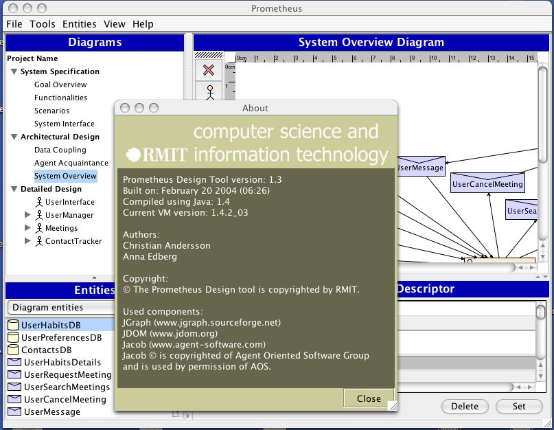
The Prometheus Design Tool (see figure 5) allows users to create and modify Prometheus designs. It
ensures that certain inconsistencies cannot be introduced and provides cross checking that detects other
forms of inconsistency. The tool can also export individual design diagrams as well as generate a report
that contains the complete design.
For more details on tool support for Prometheus see [43]. The Prometheus Design Tool is freely
available8 and further functionality is under development.
Another tool that supports the Prometheus methodology is the JACK9 Development Environment (JDE)
which provides a design tool that allows Prometheus-style overview diagrams to be drawn. The JDE can
then generate skeleton code from these diagrams. This facility has proven quite useful.
3 Case Study: Calendar System
The case study described below was set as the main assignment for the undergraduate class Agent Oriented
Programming and Design, run in the second half of 2003. Students were given a high-level description of
a calendar system and were required to produce a design using Prometheus and to implement the system
using JACK.
The description of the system provided was essentially the following.
“The calendar system supports the scheduling, rescheduling, and cancellation of meetings
involving users. When a meeting is requested with certain users the system attempts to find
a suitable time. Finding such a time may fail, may require that existing meetings are moved
automatically, or may create a double booking for certain users that must be manually resolved.
Each user has their own application instance with which they interact. These applications
can contain multiple agents that interact with the applications of other users to coordinate and
schedule meetings.
In scheduling meetings, some users may be essential to the meeting and others may not be
essential. If an essential user pulls out of a meeting after it is set (or cannot make a proposed
time) then the meeting needs to be rescheduled.
Setting or rescheduling meetings may be impossible without changing existing meetings. Do-
ing this should take care to avoid creating a “cascade” where in order to schedule meeting A,
7 Inthe general sense, not in the formal sense of a logical theory being consistent.
8 From www.cs.rmit.edu.au/agents/pdt
9 JACK is a commercial agent development platform developed by Agent Oriented Software.
8Figure 5: The Prometheus Design Tool (PDT)
9meeting B is moved which creates a clash with meeting C which is moved creating a clash
with D etc. Some possibilities for dealing with this situation include (a) assigning priorities
to meetings (and in particular marking some meetings as not movable, or only manually mov-
able); (b) using the heuristic that where a clash is created only a meeting with fewer people (or
less senior people?) will be moved.
The system should allow users to nominate when they are available (and when they are not
available) and should also allow for certain constraints to be specified such as only scheduling
a maximum of 4 hours of meetings on a certain day (e.g. to allow time to prepare a lecture).
Or, more generally, only scheduling N hours of meetings in a certain time period (M days) ”
The design that we present in this section was produced by a student, John Sietsma, as part of the course
and was developed using an earlier version of the Prometheus Design Tool. In this chapter we reproduce
(with permission) selected diagrams from John’s design.
Due to space limitations we only discuss part of the architectural design. One of the key parts of the
architectural design phase in Prometheus is deciding on the agent types that will exist in the system. This
is done by grouping functionalities, and, as discussed in section 2.4, the data coupling diagram is useful in
helping to identify possible groupings.
Figure 6 shows a data coupling diagram10 for the following functionalities:
• Contact Manager: In charge of managing contact information for other users.
• Contact Notify: Provides a means of communicating with other users.
• Meeting Manager: Manages meeting information.
• Meeting Scheduler: Schedules meetings subject to provided constraints and user habits/preferences.
• Negotiator: Negotiates with other users to determine meeting times. This differs from Meeting
Scheduler in that Negotiator is about inter-user constraints, whereas Meeting Scheduler is concerned
only with the constraints of a single user.
• User Interaction: Interacts with the user (as opposed to interacting with other users, which is done
by Contact Notify).
• User Information Manager: Manages information about the user such as their preferences.
• User Monitor: Observes user, attempting to learn their habits.
• User Notify: Reminds user of events. Differs from User Interaction (a) in that it uses a range of
communication media such as SMS, email, and so on; but also (b) in that it waits for conditions to
arise and reminds the user, rather than receiving input from the user.
In this case the student chose to create four agent types:
• UserInterface: combining the functionalities of User Interaction and User Notify. This grouping
made sense because both functionalities are concerned with interaction with the user.
• ContactTracker: based on the Contact Manager functionality and including the Contact Information
database. Although the Contact Notify functionality could have been included in this agent type, it
interacts more with the functionalities concerned with scheduling meetings and so was grouped with
them in the Meetings agent.
• Meetings: combining the functionalities of Meeting Scheduler, Meeting Manager, Negotiator and
Contact Notify; and including the Meetings Database. These functionalities are both related and
interact with each other.
10 The diagram is slightly modified from the one that was prepared by John.
10Figure 6: Data Coupling Diagram.
• UserManager: combining the User Monitor and User Information Manager functionalities; and
including the User Habits and User Preferences databases11 .
One result of this grouping was that certain agents were writing data that was in other agents. For ex-
ample, the User Interaction functionality within the UserInterface agent writes to the Meetings Database.
These writes need to be changed to messages to the appropriate agent which then updates its own data.
Having decided on the agent types we now skip ahead to the developing the agent overview diagram
from the system overview diagram. Figure 7 shows the overall design of the system. It depicts the four
agent types identified and also shows the messages between them, percepts received by the UserInterface
agent and data read and written.
In developing the agent overview diagram for the Meeting agent we begin with its interface: the data
that it reads and writes, and the incoming and outgoing messages. The next step is to develop capabilities
that will together provide the agent’s required functionality, as well as internal messages between the
capabilities.
4 Strengths and Weaknesses
As discussed in the introduction, Prometheus aims to be a practical methodology that can be used by
undergraduate students and industry practitioners. The (anecdotal) evidence supports our belief that we
have succeeded in this regard, and this is a key strength of Prometheus.
Prometheus has been developed over a number of years. During this time it has been taught to under-
graduate students, used by students doing summer projects, and been taught at industry workshops. These
activities yielded feedback that has been valuable in refining and improving the methodology.
On the industrial side, a prototype weather alerting system developed by Agent Oriented Software for
the Australian Bureau of Meteorology [39] used Prometheus overview diagrams to capture and document
the design. These diagrams were produced using the JACK Development Environment (JDE).
In order to obtain a slightly more reliable assessment of Prometheus, we have on two occasions set
summer projects12 where the student was given written description of the Prometheus methodology, in-
11 which are renamed in the final version of the design to UserHabitsDB and UserPreferencesDB respectively.
12 These are done by undergraduate students over eight weeks full time during the summer non-teaching period.
11Figure 7: Example System Overview Diagram
Figure 8: Example Agent Overview Diagram: Meeting Agent
12tentionally limited support from staff members, and was instructed to design and build an agent system.
In the 2001/2002 Christmas vacation a second year student produced a design and implementation for a
Holonic manufacturing system. In the 2002/2003 Christmas vacation a (different) student produced a de-
tailed design for a tourism application. These experiences contrast with pre-Prometheus experiences where
graduate students struggled to design agent systems and required considerable support from staff.
In our teaching we have found that the Prometheus methodology has made a significant difference. Be-
fore the methodology had been developed graduate students struggled to design and implement reasonable
agent systems, whereas now we are successfully teaching Prometheus and JACK in a one-semester course.
This course, which is taught to undergraduate students, sees most of them successfully design and build
reasonable agent systems within the period of a semester.
These experiences provide evidence that Prometheus is useful as well as being usable by its intended
target audience.
Another strength of the Prometheus methodology is the possibility and existence of tool support.
However, Prometheus is not without weaknesses. Its support for the social aspect of agents is currently
focussed on the lowest common denominator: messages and protocols. Extending the methodology to
support more specific types of agent interaction and relationships, such as teams of agents [13] and open
societies of agents, is one of the areas that we are currently focussing on. The area of software methodolo-
gies for designing open agent systems is quite new and exciting. Existing work that we intend to build on
includes [28, 32, 40].
Prometheus also does not deal at all with mobile agents. This has not been a priority as we do not
see mobility as central for intelligent agent systems. However, if a developer is designing a system where
mobility is a significant aspect, then Prometheus is likely to be inadequate as a design methodology.
Prometheus covers the system specification, high level design, and detailed design activities with some
discussion of implementation issues [44, chapter 10]. There has also been some work on using design
models to help in debugging agent systems [46, 47]. However, the support for implementation, testing and
debugging is limited at the moment. Also, Prometheus currently has less focus on early requirements and
analysis of business processes than a methodology such as Tropos. These are however all areas in which
Prometheus is undergoing development and can be expected to evolve.
Finally, Prometheus is not based on UML. This can be regarded as being either a strength or a weakness.
From the point of view of developing a methodology that is well-suited to designing agents, we feel that
not starting with a perspective that is very object-centric has been a good decision. On the other hand,
UML is clearly the standard notation13 , which most developers are familiar with. We have tried to build
on aspects of UML and Object-Oriented design where appropriate. However there are other approaches
which do this to a greater extent [45, 52].
5 Conclusion
We have briefly presented the Prometheus methodology for designing intelligent software agents and agent
systems. The methodology provides detailed guidance in terms of processes as well as notations. It is not
intended to be prescriptive, but is rather an approach which has evolved out of experience, and which the
authors expect to be further adapted, refined and developed to suit the needs of agent software developers.
Recent years have seen a substantial growth of activity in the area of SE methodologies suited to an
agent programming paradigm, As these mature and develop, and are increasingly used beyond the imme-
diate sphere of the developers, we expect them to bear fruit in terms of increased use of agent technology,
and more widespread familiarity with building of agent systems.
13 It is important to note that UML is only a notation, not a methodology. However, it is often used together with the Rational
Unified Process (RUP).
13Acknowledgements
We would like to acknowledge the support of the Australian Research Council (ARC) under grant CO010693414 ,
and its continuation, grant LP045348615 .
We would also like to thank James Harland, John Thangarajah and David Poutakidis of RMIT Uni-
versity; as well as Ralph Rönnquist, Andrew Lucas, Andrew Hodgson, Paul Maisano, and Jamie Curmi
of Agent Oriented Software, as well as the many students and workshop participants who have provided
comments, examples and feedback.
The Prometheus Design Tool was initially developed by Anna Edberg and Christian Andersson. Further
development has been by Claire Hennekam and Jason Khallouf.
References
[1] AAII. dMARS Technical Overview. The dMARS V1.6.11 System Overview, 1996.
[2] F. M. T. Brazier, B. M. Dunin-Keplicz, N. R. Jennings, and J. Treur. DESIRE: Modelling multi-
agent systems in a compositional formal framework. Int Journal of Cooperative Information Systems,
6(1):67–94, 1997.
[3] Paolo Bresciani, Paolo Giorgini, Fausto Giunchiglia, John Mylopoulos, and Anna Perini. Tropos:
An agent-oriented software development methodology. Technical Report DIT-02-0015, University of
Trento, Department of Information and Communication Technology, 2002.
[4] B. Burmeister. Models and methodology for agent-oriented analysis and design. Working Notes of
the KI’96 Workshop on Agent Oriented Programming and Distributed Systems, 1996.
[5] P. Burrafato and M. Cossentino. Designing a multi-agent solution for a bookstore with the PASSI
methodology. In Proceedings of the Fourth International Bi-Conference Workshop on Agent-Oriented
Information Systems (AOIS-2002), Toronto, 2002. Available from http://mozart.csai.unipa.it/passi/.
[6] Paolo Busetta, Nicholas Howden, Ralph Rönnquist, and Andrew Hodgson. Structuring BDI agents
in functional clusters. In Agent Theories, Architectures, and Languages (ATAL-99), pages 277–289.
Springer-Verlag, 2000. LNCS 1757.
[7] Paolo Busetta, Ralph Rönnquist, Andrew Hodgson, and Andrew Lucas. JACK Intelligent Agents
- Components for Intelligent Agents in Java. Technical report, Agent Oriented Software Pty. Ltd,
Melbourne, Australia, 1998. Available from http://www.agent-software.com.
[8] Geoff Bush, Stephen Cranefield, and Martin Purvis. The Styx agent methodology. The Information
Science Discussion Paper Series 2001/02, Department of Information Science, University of Otago,
New Zealand., 2001. Available from http://divcom.otago.ac.nz/infosci.
[9] Giovanni Caire, Francisco Leal, Paulo Chainho, Richard Evans, Francisco Garijo, Jorge Gomez, Juan
Pavon, Paul Kearney, Jamie Stark, and Philippe Massonet. Agent oriented analysis using MES-
SAGE/UML. In Michael Wooldridge, Paolo Ciancarini, and Gerhard Weiss, editors, Second Interna-
tional Workshop on Agent-Oriented Software Engineering (AOSE-2001), pages 101–108, 2001.
[10] C. Castelfranchi, F. Dignum, C. Jonker, and J. Treur. Deliberate normative agents: Principles and ar-
chitectures. In N. Jennings and Y. Lespérance, editors, Intelligent Agents VI, pages 364–378. Springer-
Verlag, 2000.
[11] Lawrence Cavedon and Liz Sonenberg. On social commitment, roles and preferred goals. In Inter-
national Conference on Multi-Agent Systems (ICMAS), 1998.
14 Simplifying the Development of Agent-Oriented Systems, ARC SPIRT Grant, 2001-2003.
15 Advanced Software Engineering Support for Intelligent Agent Systems, ARC Linkage Grant, 2004-2006
14[12] L. Cernuzzi and G. Rossi. On the evaluation of agent oriented modeling methods. In Proceedings
of the OOPSLA 2002 Workshop on Agent-Oriented Methodologies, pages 21–30, Seattle, November
2002.
[13] P. R. Cohen and H. J. Levesque. Teamwork. Nous, 25(4):487–512, 1991.
[14] Anne Collinot, Alexis Drogoul, and Philippe Benhamou. Agent oriented design of a soccer robot
team. In Proceedings of ICMAS’96, 1996.
[15] M. Cossentino and C. Potts. A CASE tool supported methodology for the design of multi-agent
systems. In Proceedings of the International Conference on Software Engineering Research and
Practice (SERP’02), Las Vegas, 2002. Available from http://mozart.csai.unipa.it/passi/.
[16] R. Scott Cost, Ye Chen, Tim Finin, Yannis Labrou, and Yun Peng. Using colored Petri
nets for conversation modeling. In Workshop on Agent Communication Languages at the Six-
teenth International Joint Conference on Artificial Intelligence (IJCAI-99), 1999. Available from
http://www.csee.umbc.edu/∼jklabrou/.
[17] Khanh Hoa Dam. Evaluating agent-oriented software engineering methodologies. Master’s thesis,
School of Computer Science and Information Technology, RMIT University, Melbourne, Australia,
2003. (supervisors: Michael Winikoff and Lin Padgham).
[18] Khanh Hoa Dam and Michael Winikoff. Comparing agent-oriented methodologies. In Paolo Giorgini
and Michael Winikoff, editors, Proceedings of the Fifth International Bi-Conference Workshop on
Agent-Oriented Information Systems, pages 52–59, Melbourne, Australia, 2003.
[19] J. Debenham and B. Henderson-Sellers. Full lifecycle methodologies for agent-oriented systems
– the extended OPEN process framework. In Proceedings of Agent-Oriented Information Systems
(AOIS-2002) at CAiSE’02, Toronto, 2002.
[20] Scott A. DeLoach, Mark F. Wood, and Clint H. Sparkman. Multiagent systems engineering. Interna-
tional Journal of Software Engineering and Knowledge Engineering, 11(3):231–258, 2001.
[21] A. Drogoul and J. Zucker. Methodological issues for designing multi-agent systems with machine
learning techniques: Capitalizing experiences from the robocup challenge. Technical Report LIP6
1998/041, Laboratoire d’Informatique de Paris 6, 1998.
[22] M. Elammari and W. Lalonde. An agent-oriented methodology: High-level and intermediate models.
In G. Wagner and E. Yu, editors, Proc. of the 1st Int. Workshop. on Agent-Oriented Information
Systems., 1999.
[23] Martin Fowler and Kendall. UML Distilled: A Brief Guide to the Standard Object Modeling Language
(third edition). Object Technology Series. Addison-Wesley, 2003.
[24] M. P. Georgeff and A. L. Lansky. Procedural knowledge. Proceedings of the IEEE Special Issue on
Knowledge Representation, 74:1383–1398, 1986.
[25] Fausto Giunchiglia, John Mylopoulos, and Anna Perini. The Tropos software development methodol-
ogy: Processes, models and diagrams. In Third International Workshop on Agent-Oriented Software
Engineering, 2002.
[26] Norbert Glaser. The CoMoMAS methodology and environment for multi-agent system development.
In Chengqi Zhang and Dickson Lukose, editors, Multi-Agent Systems Methodologies and Applica-
tions, pages 1–16. Springer LNAI 1286, 1996. Second Australian Workshop on Distributed Artificial
Intelligence.
[27] Marcus J. Huber. JAM: A BDI-theoretic mobile agent architecture. In Proceedings of the Third
International Conference on Autonomous Agents, (Agents’99), pages 236–243, Seattle, WA, 1999.
15[28] Marc-Philippe Huget. Nemo: an agent-oriented software engineering methodology. In Proceedings
of the OOPSLA 2002 Workshop on Agent-Oriented Methodologies, pages 41–53, Seattle, 2002.
[29] Marc-Philippe Huget, James Odell, Øystein Haugen, Mariam “Misty” Nodine, Stephen Cranefield,
Renato Levy, and Lin Padgham. Fipa modeling: Interaction diagrams. On www.auml.org under
“Working Documents”, 2003. FIPA Working Draft (version 2003-07-02).
[30] Carlos Iglesias, Mercedes Garijo, and José González. A survey of agent-oriented methodologies. In
Jörg Müller, Munindar P. Singh, and Anand S. Rao, editors, Proceedings of the 5th International
Workshop on Intelligent Agents V : Agent Theories, Architectures, and Languages (ATAL-98), pages
317–330. Springer-Verlag: Heidelberg, Germany, 1999.
[31] Carlos Argel Iglesias, Mercedes Garijo, José C. González, and Juan R. Velasco. Analysis and design
of multiagent systems using MAS-commonKADS. In Agent Theories, Architectures, and Languages,
pages 313–327, 1997.
[32] T. Juan, A. Pearce, and L. Sterling. ROADMAP: Extending the Gaia methodology for complex
open systems. In Proceedings of the First International Joint Conference on Autonomous Agents and
Multi-Agent Systems (AAMAS 2002), pages 3–10. ACM Press, 2002.
[33] E. A. Kendall, M. T. Malkoun, and C. H. Jiang. A methodology for developing agent based systems.
In Chengqi Zhang and Dickson Lukose, editors, First Australian Workshop on Distributed Artificial
Intelligence, 1995.
[34] David Kinny and Michael Georgeff. Modelling and design of multi-agent systems. In Intelligent
Agents III: Proceedings of the Third International Workshop on Agent Theories, Architectures, and
Languages (ATAL-96). LNAI 1193. Springer-Verlag, 1996.
[35] David Kinny, Michael Georgeff, and Anand Rao. A methodology and modelling technique for sys-
tems of BDI agents. In Seventh European Workshop on Modelling Autonomous Agents in a Multi-
Agent World, 1996.
[36] Jürgen Lind. A development method for multiagent systems. In Cybernetics and Systems: Proceed-
ings of the 15th European Meeting on Cybernetics and Systems Research, Symposium “From Agent
Theory to Agent Implementation”, 2000.
[37] Michael Luck, Peter McBurney, and Chris Preist. Agent technology: Enabling next gener-
ation computing: A roadmap for agent-based computing. AgentLink report, available from
www.agentlink.org/roadmap, 2003. ISBN 0854 327886.
[38] Nowostawski M., Purvis M., and Cranefield S. A layered approach for modelling agent conversations.
In Proceedings of the 2nd International Workshop on Infrastructure for Agents, MAS, and Scalable
MAS, 5th International Conference on Autonomous Agents, Montreal, pages 163–170, 2001.
[39] Ian Mathieson, Sandy Dance, Lin Padgham, Malcolm Gorman, and Michael Winikoff. An open
meteorological alerting system: Issues and solutions. In Vladimir Estivill-Castro, editor, Proceedings
of the 27th Australasian Computer Science Conference, pages 351–358, Dunedin, New Zealand,
2004.
[40] Philippe Mathieu, Jean-Christophe Routier, and Yann Secq. Towards a pragmatic methodology for
open multi-agent systems. In Proceedings of the 14th International Symposium on Methodologies for
Intelligent Systems (ISMIS), pages 206–210, Maebashi City, Japan, 2003.
[41] J. Odell, H. Parunak, and B. Bauer. Extending UML for agents. In Proceedings of the Agent-Oriented
Information Systems Workshop at the 17th National conference on Artificial Intelligence., 2000.
[42] Lin Padgham and Patrick Lambrix. Agent capabilities: Extending BDI theory. In Proceedings of
Seventeenth National Conference on Artificial Intelligence - AAAI 2000, pages 68–73, 2000.
16[43] Lin Padgham and Michael Winikoff. Prometheus: A pragmatic methodology for engineering intelli-
gent agents. In Proceedings of the OOPSLA 2002 Workshop on Agent-Oriented Methodologies, pages
97–108, Seattle, 2002.
[44] Lin Padgham and Michael Winikoff. Developing Intelligent Agent Systems: A Practical Guide. John
Wiley and Sons, 2004. ISBN 0-470-86120-7.
[45] M. Papasimeon and C. Heinze. Extending the UML for designing JACK agents. In Proceedings of
the Australian Software Engineering Conference (ASWEC 01), 2001.
[46] David Poutakidis, Lin Padgham, and Michael Winikoff. Debugging multi-agent systems using design
artifacts: The case of interaction protocols. In Proceedings of the First International Joint Conference
on Autonomous Agents and Multi Agent Systems (AAMAS’02), 2002.
[47] David Poutakidis, Lin Padgham, and Michael Winikoff. An exploration of bugs and debugging in
multi-agent systems. In Proceedings of the 14th International Symposium on Methodologies for
Intelligent Systems (ISMIS), pages 628–632, Maebashi City, Japan, 2003.
[48] Onn Shehory and Arnon Sturm. Evaluation of modeling techniques for agent-based systems. In
Proceedings of the Fifth International Conference on Autonomous Agents, pages 624–631. ACM
Press, 2001.
[49] Arnon Sturm and Onn Shehory. A framework for evaluating agent-oriented methodologies. In Paolo
Giorgini and Michael Winikoff, editors, Proceedings of the Fifth International Bi-Conference Work-
shop on Agent-Oriented Information Systems, pages 60–67, Melbourne, Australia, 2003.
[50] A. van Lamsweerde. Goal-oriented requirements engineering: A guided tour. In Proceedings of the
5th IEEE International Symposium on Requirements Engineering (RE’01), pages 249–263, Toronto,
2001.
[51] L. Z. Varga, N. R. Jennings, and D. Cockburn. Integrating intelligent systems into a cooperating
community for electricity distribution management. Int Journal of Expert Systems with Applications,
7(4):563–579, 1994.
[52] Gerd Wagner. A UML profile for external AOR models. In Third International Workshop on Agent-
Oriented Software Engineering, 2002.
[53] Michael Winikoff, Lin Padgham, and James Harland. Simplifying the development of intelligent
agents. In AI2001: Advances in Artificial Intelligence. 14th Australian Joint Conference on Artificial
Intelligence, pages 555–568. Springer, LNAI 2256, 2001.
[54] M. Wooldridge, N.R. Jennings, and D. Kinny. The Gaia methodology for agent-oriented analysis and
design. Autonomous Agents and Multi-Agent Systems, 3(3), 2000.
[55] Michael Wooldridge. An Introduction to MultiAgent Systems. John Wiley & Sons (Chichester, Eng-
land), 2002. ISBN 0 47149691X, http://www.csc.liv.ac.uk/∼mjw/pubs/imas/.
[56] Pınar Yolum and Munindar P. Singh. Flexible protocol specification and execution: Applying event
calculus planning using commitments. In Proceedings of the 1st Joint Conference on Autonomous
Agents and MultiAgent Systems (AAMAS), pages 527–534, 2002.
17You can also read