Automatic design system for generating routing layout of tubes, hoses, and cable harnesses in a commercial truck
←
→
Page content transcription
If your browser does not render page correctly, please read the page content below
Journal of Computational Design and Engineering, 2021, 8(4), 1098–1114

                                                                     https://doi.org/10.1093/jcde/qwab034
                                                                     Journal homepage: www.jcde.org

RESEARCH ARTICLE

Automatic design system for generating routing layout

                                                                                                                                                        Downloaded from https://academic.oup.com/jcde/article/8/4/1098/6316573 by guest on 21 October 2021
of tubes, hoses, and cable harnesses in a commercial
truck
Saekyeol Kim 1 , Shinyu Kim2 , Taeheok Choi2 , Taejoon Kwon2 ,
Tae Hee Lee 1,2, * and Kwangrae Lee3
1
 BK21 Four Educational and Research Program for Automotive-Software Convergence, Hanyang University,
Seoul 04763, South Korea; 2 Department of Automotive Engineering, Hanyang University, Seoul 04763, South
Korea and 3 Commercial Vehicle Engineering Data Management Team, Hyundai Motor Company, 150
Hyundaiyeonguso-ro, Namyang-eup, Hwaseong-si, Gyeonggi-do 18280, South Korea
*Corresponding author. E-mail: thlee@hanyang.ac.kr    http://orcid.org/0000-0002-3876-1134

Abstract
Although many routing algorithms have been developed, it is difficult for designers in the automotive industry to adopt
them because of the complicated preliminary steps that are required. This study presents a systematic framework for
generating the routing layout of the tubes, hoses, and cable harnesses in a commercial truck. The routing layout design
problem in a commercial truck is analysed and defined. For routing operations, a sequential graph-based routing algorithm
is employed to rapidly provide a routing solution. Because a reference routing layout design does not exist in most
engineering problems, a cell-based genetic algorithm combined with a modified maze algorithm is employed to generate a
reference design. To consider the clamping condition of the routing components, a new fitness function in the genetic
algorithm is implemented. The numerical study shows that the proposed routing algorithm provides a better reference
routing layout design than the conventional algorithm. The proposed automatic design system was applied to the routing
layout design problem of a commercial truck. It was demonstrated that the proposed framework satisfies all industrial
practitioners’ functional requirements and provides a systematic method of solving the routing layout design problem,
considering all its characteristics.

Keywords: automatic design system; commercial truck; Dijkstra’s algorithm; genetic algorithm; routing layout design; routing
algorithm

1. Introduction                                                              ucts. In addition, the current pandemic of the coronavirus dis-
                                                                             ease (COVID-19) has increased the demand for an automatic vir-
Achieving design automation is a priority in many industries
                                                                             tual design and assembly system. As the design and production
where companies are required to produce high-quality prod-
                                                                             of engineering products are based on the global supply chain,
ucts that satisfy the customers’ requirements while complying
                                                                             many international manufacturers have suffered massive de-
with various governmental regulations. Despite these restric-
                                                                             lays in design, assembly, and production during the shutdown
tions, companies are expected to lower the cost of their prod-

Received: 31 December 2020; Revised: 9 April 2021; Accepted: 17 May 2021
C The Author(s) 2021. Published by Oxford University Press on behalf of the Society for Computational Design and Engineering. This is an Open Access

article distributed under the terms of the Creative Commons Attribution-NonCommercial License (http://creativecommons.org/licenses/by-nc/4.0/),
which permits non-commercial re-use, distribution, and reproduction in any medium, provided the original work is properly cited. For commercial
re-use, please contact journals.permissions@oup.com

                                                                                                                                            1098
Journal of Computational Design and Engineering, 2021, 8(4), 1098–1114                      1099

and stringent social distancing around the world. For instance,
many global automotive manufacturers have suffered a mas-
sive shortage of electrical cable harnesses and their prototypes,
which are essentially required in the layout design process, dur-
ing the early stage of the COVID-19 pandemic. Design and as-
sembly schedules were also unexpectedly and continuously de-
layed because the layout design of routing components is usu-
ally achieved through frequent interactions and off-line meet-
ings between many design teams, who are in charge of different
vehicular components. The automatic design system for gener-
ating the routing layout of tubes, hoses, and cable harnesses is
one of the core technologies for resolving current challenges in
the automobile industry.
    The layout design automation of long and round products,
such as pipe design in ships or cable harnesses in vehicles, has

                                                                                                                                                        Downloaded from https://academic.oup.com/jcde/article/8/4/1098/6316573 by guest on 21 October 2021
always been a research interest. Routing layout design is a pro-
                                                                     Figure 1: Tubes, hoses, and cable harnesses under the cab of a commercial truck.
cess that finds a satisfactory route for these components, con-
nected from their starting points to their end points under vari-
ous design constraints. For instance, pipe routing layout design     much attention in the industry. Manually creating the routing
is a critical design step during the detailed design phase in ship   design of these components has become extremely inefficient,
design, because more than 50% of the total person hours are          resulting in poor quality because vehicle development time has
spent at this step (Park & Storch, 2002). An enormous amount of      been considerably shortened. Because the routing layout is very
information and constraints must be managed to obtain the lay-       sensitive to the design of other automobile components, fre-
out design of routing components. Material and production cost,      quent design change in these components causes a bottleneck
assembly and installation cost, accessibility and maintenance,       in the design and manufacturing process. Moreover, routing lay-
and space availability are vital factors that companies have to      out design has been assigned the lowest priority because this
consider at this step. Although many skilled designers and en-       procedure has been underestimated in the automobile indus-
gineers manage this routing operation, two critical and funda-       try. This has caused considerable wastage of person hours and
mental problems must be overcome. First, the routing layout de-      has deteriorated the efficiency of the design and manufacturing
sign is highly dependent on the knowledge and experience of the      procedure. Finally, routing is incredibly challenging because a
designers and engineers. Based on their know-how and prefer-         reference routing layout design does not exist in most industrial
ences, the design and its validation can vary and yield incon-       problems.
sistent results. Second, conventional design methodologies are           Despite the importance of the routing layout design prob-
manually carried out by practitioners using computer-aided de-       lem, only a few researchers have addressed it in the automo-
sign (CAD) software. This requires a time-consuming process of       bile industry. The assembly procedure of a wiring harness was
trial-and-error, massive collaboration between a large number        optimized (Kobayashi et al., 2014). Researchers from Volvo and
of different teams, and intensive teamwork. Many routing algo-       Chalmers University of Technology found a new cab-chassis
rithms have been proposed for finding a routing solution with-       electrical wiring harness routing layout (Drotz & Huber, 2014).
out involving manual operations. As most of these algorithms         Dijkstra’s and A∗ algorithms have been adopted to solve the
work for some simple problems, they are challenging to imple-        route optimization problem of a flexible 1D component with
ment in the design process in the industry. For these reasons,       manufacturing constraints (Hermansson et al., 2016). The rout-
some studies have developed an automatic pipe design system          ing layout of the air conditioning (AC) hose found using this
to solve these fundamental problems, and some useful results         method was satisfactory. The A∗ algorithm significantly de-
for the ship design industry were obtained (Asmara, 2013; Kim        creased the computational time, but this method required a
et al., 2013).                                                       user-defined function. In a previous work, our research team de-
    The electrification of vehicles and the implementation of ad-    veloped a graph-based routing algorithm (Kim et al., 2021). The
vanced electronic vehicle control systems have caused a rapid        limitation of earlier studies is that they focused on predicting ve-
increase in the number of electrical cables and wires used in        hicular performance or proposing a new routing structure or al-
automobiles (Drotz & Huber, 2014). Thus, a free design space         gorithm. However, conventional methodologies cannot be easily
is no longer available for routing components. The conven-           generalized or adopted in industrial applications without knowl-
tional engines and battery-supplied electric powertrain compo-       edge or experience in routing algorithms.
nents need to be accommodated in a densely packed vehicu-                This study presents an automatic design system for gener-
lar system, as today’s automobile companies are focusing more        ating the routing layout of tubes, hoses, and cable harnesses of
on electrified and hybrid solutions. Hence, the geometric inter-     a commercial truck to address the issues mentioned above in
ference with other automotive parts should be carefully eval-        the automotive industry. A commercial truck was selected as
uated for each routing component (Hermansson et al., 2013,           the target vehicle in this study because it has a relatively large
2016).                                                               number of tubes, hoses, and cable harnesses compared to other
    Therefore, the routing layout design of various tubes, hoses,    vehicular types. The number of these routing components is
and cable harnesses has become an essential task in the auto-        expected to significantly increase as vehicles adopt more elec-
motive industry. Figure 1 shows some of the targeted compo-          tronics in the near future. In addition, a validation procedure
nents in a commercial truck. There are some challenges to the        for routing layout design, which is obtained from the routing
automobile industry. First, automobile companies lack skilled        operation, should be established because reference routing lay-
designers and experts because, to date, the routing layout de-       out designs do not exist in the early design stage or during
sign of these tubes, hoses, and cable harnesses has not attracted    the vehicle development process. This study had three main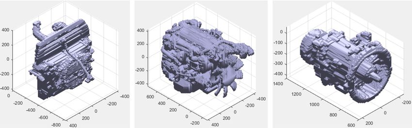
1100      Automatic routing design system for commercial trucks

objectives. The first objective was to develop an automatic de-        bination of these conventional methods has been developed to
sign system for generating the routing layout of tubes, hoses,         overcome their limitations (Liu & Wang, 2012). In our previous
and cable harnesses of a commercial truck. This system would           work, routing algorithms were reviewed in detail (Kim et al.,
facilitate the route design process of these components, lower         2021).
the dependence on the experts’ know-how and the interactions               The main problem with these routing algorithms is that they
between design teams, and reduce the time required for repeti-         cannot be widely used in industry. The designers and practi-
tive design changes during manual operations of the design, as-        tioners not only need to understand the fundamental back-
sembly, and manufacturing processes. The second objective was          ground theories of each routing algorithm but should also be
to develop a routing algorithm that provides a reference layout        able to carry out the entire pre- and post-processing. To enhance
design for validating the routing results during the vehicle devel-    the applicability of routing algorithms, several researchers have
opment process. The third objective was to apply the proposed          developed routing design systems to improve the work effi-
automatic design system and routing algorithm to the engineer-         ciency of practitioners and designers. The development of a
ing example of a commercial truck. The remainder of this paper         design system is one of the most demanding and challenging
is organized as follows: In the next section, a literature review of   tasks. In the early stages of research, many researchers con-
the routing algorithm and the automatic routing design system          structed a decision-making framework to support pipe design-

                                                                                                                                             Downloaded from https://academic.oup.com/jcde/article/8/4/1098/6316573 by guest on 21 October 2021
for various industrial applications is presented. In Section 3, the    ers. A knowledge-based prototype expert system for ship pipe
routing design problem for a commercial truck is described. Sec-       design was developed (Kang et al., 1999). A design framework
tion 4 presents the proposed automatic design system, includ-          that selects a satisfactory routing path for every pipeline in a
ing the adopted routing algorithms. In Section 5, the proposed         ship engine room was proposed (Park, 2002); this methodol-
automatic design system is applied to six routing components           ogy considered design constraints like material and installation
in a commercial truck. The routing algorithm, which was devel-         costs. An automatic pipe model generation method based on
oped for design validation, was also compared with the conven-         the hull structural model was also proposed (Roh et al., 2007),
tional routing algorithm. Finally, conclusions are presented in        which automatically updated the pipe route design as the hull
Section 6.                                                             structural design was changed. An automatic pipe routing sys-
                                                                       tem was proposed for ship design (Kim et al., 2013), which uti-
                                                                       lized a graph-based design domain and Dijkstra’s algorithm to
                                                                       find the shortest pipe route. In addition, this system exported
2. Literature Review
                                                                       the routing results of the algorithm to the CAD system. A pipe
This section reviews various routing algorithms and some prac-         routing methodology for ship design was developed and imple-
tical approaches for applying these techniques to an automatic         mented into a prototype software package (Asmara, 2013). How-
system and designing the routes of components. Several au-             ever, the knowledge of experienced ship pipe designers was re-
tomatic design systems have been developed to generate pipe            flected in the development of this methodology. Therefore, it is
routes in ships, pipe networks, and aircraft, and we believe that      significantly challenging to employ it in the routing problems of
these can be extended to the routing problem of tubes, hoses,          other industries. Similar studies have been performed in other
and electrical cable harnesses in automobile design.                   industries. An automatic intelligent system was developed for
    An early study of the routing problem was primarily per-           designing the routes of electrical wires and pipes in aircraft (Van
formed to solve the shortest collision-free path problem. Dijk-        der Velden et al., 2007). Knowledge-based engineering methods
stra’s, Maze, network-based, Escape, and A∗ algorithms are some        and a grid-based A∗ algorithm were used to obtain the route de-
of the early research outcomes that provide the basic ideas and        sign. Meanwhile, FE and CAD software were integrated to show
fundamental concepts of routing algorithms. Many routing al-           the routing results and facilitate the designers’ work. A routing
gorithms have been developed over the past two decades based           software was developed that optimized natural gas pipe net-
on these research studies. The aforementioned classical algo-          works using GA (El-Mahdy et al., 2010). This software yielded
rithms were reviewed in some doctoral dissertations (Park, 2002;       promising solutions that minimized network costs. Table 1 sum-
Asmara, 2013).                                                         marizes previously conducted studies related to the develop-
    As the routing algorithm is the core technology in the auto-       ment of these systems. These systems were applied to solve
matic design system for routing layouts, routing algorithms are        some engineering design problems in shipbuilding and aircraft
briefly reviewed. The routing algorithms currently used for lay-       industries, e.g. the pipe route design in the ship engine room
out design consist of two basic steps: (1) definition of the design    and the route design of electrical wiring harnesses and pipes in
domain and (2) identification of the route solution in the defined     aircraft.
design domain that satisfies the design constraints. The existing          Although many routing algorithms have been proposed, a
routing algorithms, which have been developed thus far, use nu-        unified methodology that can be employed for routing prob-
merous methods to define the design domain and identify the            lems across industries has not been established because the de-
routing layout with the shortest length. In the first step, the de-    sign objectives and the geometric and economic constraints are
sign domain is defined by cells or grids using meshes, or graph        highly dependent on the characteristics of the routing layout
or network based on vertices and edges. The second step deter-         problem and industry type. Moreover, routing algorithms are im-
mines the routing layout based on the design domain, and is ac-        practical because designers and engineers have no prior knowl-
complished using many different algorithms. The classical ap-          edge of routing algorithms. Some studies have been conducted
proaches, e.g. Dijkstra’s algorithm, Maze algorithm (MA), or sim-      to construct expert systems or automatic piping systems. De-
ple rule-based algorithm (Park, 2002), still comprise a large pro-     spite promising results in some industrial fields, a wide range of
portion of the algorithms used to accomplish this task, whereas        applications of these software is yet to be realized.
heuristic algorithms such as the genetic algorithm (GA; Niu et             Our research team has developed a routing algorithm to
al., 2016; Sui & Niu, 2016), particle swarm optimization (Dong         solve the routing layout design problem in the automobile in-
& Lin, 2017), and ant colony optimization (Qu et al., 2016) algo-      dustry (Kim et al., 2021). Although it improved the efficiency of
rithms have also been extensively adopted. In addition, a com-         the routing operation, validating the results during the vehicle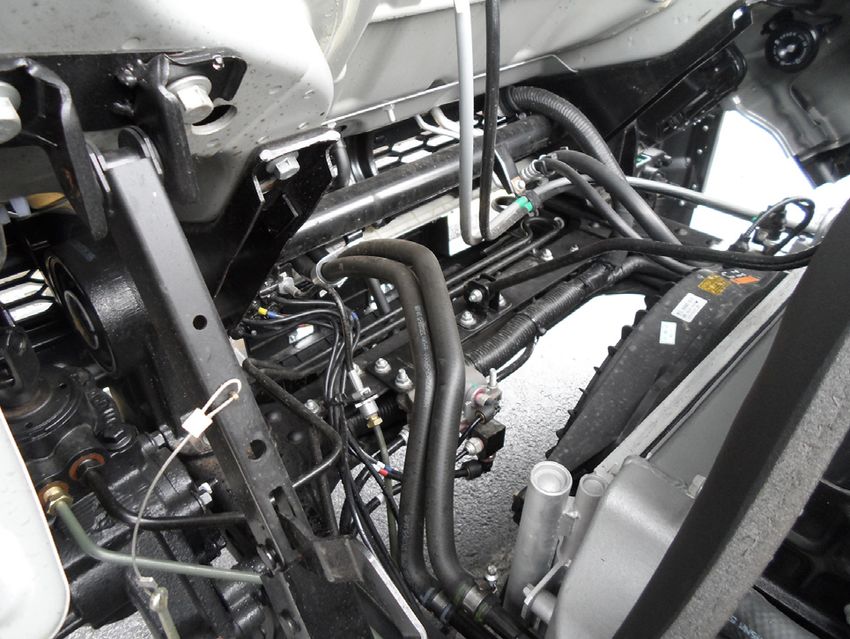
Journal of Computational Design and Engineering, 2021, 8(4), 1098–1114               1101

Table 1: Summary of routing layout design systems in related studies.

                    Type                                                Function                                         Application

          Design expert system              Support pipe routing design in a CAD system (Kang et al., 1999)
          Design expert system              Support decision making, visualization by a CAD system (Park,
                                                                          2002)                                     Shipbuilding industry
        Model generation system             Generation of a parametric pipe model in a CAD system (Roh et
                                                                        al., 2007)
        Automatic design system               Implementation of the automatic pipe route design module
                                                           into a CAD system (Kim et al., 2013)
        Automatic design system                 Prototype software package integrated with commercial
                                                                 software (Asmara, 2013)
    Automatic layout routing system         Integration of the layout route system with CAD system and FE             Aircraft industry
                                                          software (Van der Velden et al., 2007)
      Network optimization system            Natural gas pipe network optimization (El-Mahdy et al., 2010)              Pipe network

                                                                                                                                                 Downloaded from https://academic.oup.com/jcde/article/8/4/1098/6316573 by guest on 21 October 2021
                                                                         3.1. Characteristics of the routing layout design
                                                                              problem
                                                                         The characteristics of the routing layout design problem in a
                                                                         commercial truck should be carefully investigated by experts
                                                                         in the automobile industry. Some general characteristics of the
                                                                         routing layout design problem obtained after intensive discus-
                                                                         sions with the designers and engineers in the industrial field are
                                                                         summarized as follows:

                                                                         1. There are many tubes, hoses, and cable harnesses that need
                                                                            to be routed in a limited design space.
                                                                         2. There are many layout design candidates for each routing
                                                                            component because commercial trucks have a longer vehic-
                                                                            ular structure than other vehicle types.
                                                                         3. The priority of the routing components in the layout design
                                                                            should be determined by the company’s internal guidelines.
                                                                         4. The profusion of automobile components should be consid-
                                                                            ered as an obstacle to the routing process.
                                                                         5. Branches and multiple terminals should be considered in the
                                                                            routing process.
Figure 2: Targeted commercial truck.                                     6. The routing layout design must be obtained rapidly to deal
                                                                            with the frequent design changes of other automobile parts
development process remains challenging because a reference                 and collaborations with other design teams.
layout design does not usually exist. In addition, a vehicle prod-       7. A reference routing layout design is required for validation
uct production cycle is too short for practitioners to learn the            during the vehicle development process.
routing algorithm and integrate it with the various types of soft-
ware used for routing layout design. Hence, the demand for an                The CAD model and routing components of the targeted
automatic routing design system in the automobile industry and           commercial truck are shown in Fig. 3. The name of the commer-
a routing algorithm that generates a reference layout design is          cial truck is undisclosed in this study because it is proprietary in-
rapidly increasing.                                                      formation belonging to the sponsoring company. Although some
                                                                         vehicular components are not shown in the model, it can be ap-
                                                                         preciated that all the listed characteristics should be considered
3. Routing Layout Design Problem in a                                    in the routing algorithm.
   Commercial Truck
The routing layout design problem is commonly encountered                3.2. Functional requirements for the automatic design
in the automobile industry. Unfortunately, previous studies on                system
routing algorithms or automatic design systems for automotive
                                                                         The functional requirements of an automatic design system
vehicles are extremely limited. To develop an automatic design
                                                                         should be discussed with design practitioners. After intensive
system for generating the layout design of tubes, hoses, and ca-
                                                                         discussions with the designers and engineers in the industrial
ble harnesses of a commercial truck, some important character-
                                                                         field, the following issues were selected as top priorities for in-
istics of the routing layout design problem and the functional
                                                                         corporation into the automatic design system.
requirements for the routing design system should be investi-
gated. The commercial truck used in this study is illustrated in         1. All layers of the system must be programmed using a single
Fig. 2.                                                                     software (MATLAB) for the convenience of the practitioners.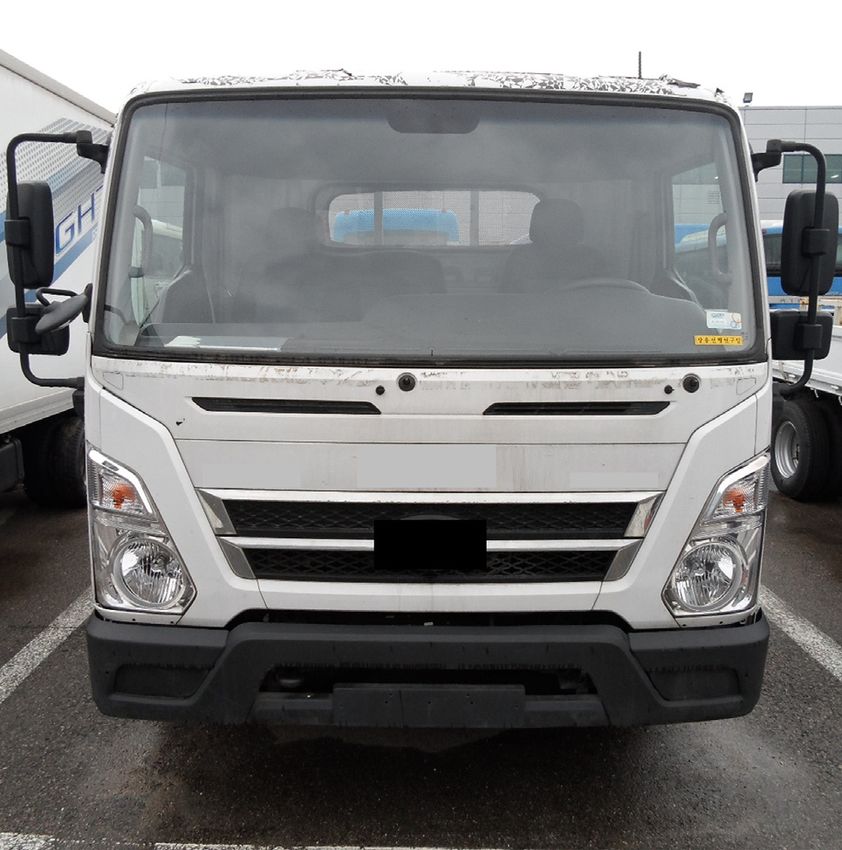
1102       Automatic routing design system for commercial trucks

                                                                                                                                                          Downloaded from https://academic.oup.com/jcde/article/8/4/1098/6316573 by guest on 21 October 2021
Figure 3: CAD model and routing components of the targeted vehicle (Kim et al., 2021).

2. A model simplification module is required to reduce the com-                      components, e.g. tubes, hoses, and cable harnesses, is usually
   plexity of the entire CAD model of the vehicle.                                   determined by the designers or the company’s internal guide-
3. Practitioners should be able to obtain routing layout designs                     lines.
   before the final CAD model of the vehicle is determined.                              Subsequently, at the data layer, model information is ex-
4. The starting point(s), end point(s), and intermediate points of                   tracted from the simplified CAD model, and the terminals and
   the layout design and the priority order of the routes should                     intermediate points for each routing component are deter-
   be separately assigned by the practitioners (Excel).                              mined. The intermediate points, which are determined by the
5. A rapid routing design support module that assists the rout-                      designers, help to determine the routing path in the design sup-
   ing operation and a design validation module that provides                        port module. The simplified CAD model is exported in the STL
   a reference routing layout design must be included.                               format from CATIA and imported into MATLAB. The model in-
6. Output results of the routing algorithm should be exported                        formation includes all its vertices and faces. Figure 6 shows an
   to the CAD software.                                                              example of the simplified CAD models of the targeted commer-
                                                                                     cial truck imported into MATLAB. In this example, the cooling
                                                                                     module, engine, and transmission were simplified using a grain
4. Proposed Automatic Routing Design                                                 size of 5 mm. The location data of the terminals and the inter-
   System                                                                            mediate points are listed in Table 2. Terminals and intermediate
                                                                                     points are abbreviated as T and I, respectively. The left-hand and
This section presents the proposed automatic design system
                                                                                     right-hand sides are abbreviated as LS and RS, respectively. Fi-
and the implemented routing algorithms. The proposed frame-
                                                                                     nally, the design domain of the problem is defined based on the
work for the automatic routing design system is shown in Fig. 4.
                                                                                     model information and the locations of the terminals and inter-
                                                                                     mediate points. The routing problem can be redefined through
4.1. Definition of routing layout design problem                                     the editor layer based on the results of the routing algorithms to
                                                                                     consider more obstacles or routing components.
At the input layer, a simplified CAD model is created, and the
priority order of the tubes, hoses, and cable harnesses is deter-
mined. The CAD model of an automotive vehicle cannot be di-
                                                                                     4.2. Routing algorithm for supporting routing operation
rectly used as an obstacle in the system layer because it is usu-
ally too complex. Additionally, it is not practical to use the entire                The purpose of the design support module is to rapidly provide
model because the computational time drastically increases as                        practitioners with a routing solution. Thus, a sequential graph-
the complexity of the model increases.                                               based routing algorithm developed by our research team was
    Figure 5 shows an example of model simplification (Black,                        adopted because it provides satisfactory results within a short
2017). Among the several existing CAD software, CATIA V5 R20                         time (Kim et al., 2021). The results of this algorithm allow auto-
is selected because it provides valuable tools and is extensively                    mobile designers and engineers in the industry to deal with fre-
used in the automobile industry. To simplify the CAD model, this                     quent design changes in other automobile components, as well
study utilized the wrapping tool in the CATIA software. This tool                    as numerous layout change requests from other teams.
wraps the original model using a virtual surface and generates                          Routing algorithms can be classified as graph-based and cell-
a new CAD model based on the wrapped surface. The precision                          based routing algorithms, depending on their design domains.
of the simplification was determined by the user’s defined grain                     The cell-based routing algorithm can provide a routing solution
size. The routing design procedure becomes accurate but more                         close to optimum when the cell size is very small. However, this
time consuming as the grain size is reduced. Thus, the level                         requires a large amount of computational time, which is not
of complexity and the number of obstacles are determined by                          suitable for supporting the routing operation of designers. On
considering the time limit. The priority order of the targeted                       the other hand, the graph-based routing algorithm can easily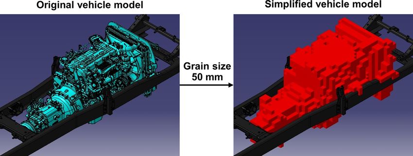
Journal of Computational Design and Engineering, 2021, 8(4), 1098–1114        1103

                                                                                                                                                Downloaded from https://academic.oup.com/jcde/article/8/4/1098/6316573 by guest on 21 October 2021
Figure 4: Framework of the proposed automatic routing design system.

control the computational time because vertices and edges are              lems instead of the original one. The graph for each design sub-
usually generated by user-defined rules. The sequential graph-             domain is much less complicated than the graph covering the
based routing algorithm implements the following strategies to             entire design domain. This makes it possible to significantly re-
deal with the characteristics of routing problems in the automo-           duce computational time.
tive industry: (1) division of design domain, (2) design of experi-            Most graph-based routing algorithms propose their own
ment technique, (3) intermediate point, and (4) minimum span-              rules to determine the vertices of a graph. This may be efficient,
ning tree.                                                                 but it is highly dependent on routing problems and is not gen-
    The graph plays the most crucial role in a graph-based rout-           erally applicable. This routing algorithm implements the design
ing algorithm because it determines the candidate paths for                of experiment (DoE) technique to provide a general approach for
the routing layout design. Because the entire design domain is             determining the vertices of a graph. Among various DoE tech-
too large and obstacles in automotive applications have com-               niques, a full factorial design was adopted to improve the uni-
plicated shapes, a graph with a very large number of vertices is           formity of vertices in the design subdomain.
required to solve this routing problem. This drastically increases             The terminals in automotive applications are usually located
the computational time. Hence, the design domain is divided                far apart. Intermediate points are adopted to facilitate the rout-
into several design subdomains to solve several routing prob-              ing procedure in the algorithm. There are three main functions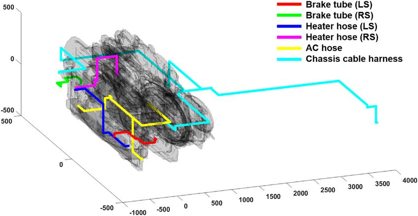
1104 Automatic routing design system for commercial trucks
domain until the routing layout design is obtained. This proce-
dure is operated sequentially according to the priority order of
the tubes, hoses, and cable harnesses of the commercial truck.
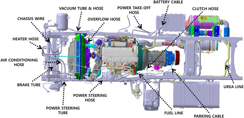
The routing process is described using a simple routing lay-
out design example to elucidate the routing algorithm. The rout-
ing problem, which is illustrated in Fig. 8, has three terminals
and two intermediate points. The figures below represent the
floor plan and the side view. The routing algorithm divides the
design domain and determines the routing layout design accord-
ing to the following rules. The first design subdomain is defined
by using the first terminal and the first intermediate point. In
this design subdomain, the vertices are created using a five-level
full factorial design, where they are made equidistant by divid-
ing the differences between the x-, y-, and z-coordinates of these
two points, respectively. Vertices located inside the obstacle are
Downloaded from https://academic.oup.com/jcde/article/8/4/1098/6316573 by guest on 21 October 2021
excluded. A graph in the design subdomain is then created, and
Figure 5: Example of CAD model simplification. the distance between all remaining vertices is calculated using
Dijkstra’s algorithm, whereas the paths that pass through the
obstacle are excluded. If there are only two points that should
of the intermediate points. First, the design domain is divided
be connected, Dijkstra’s algorithm provides the shortest route.
into design subdomains based on these points. Second, the in-
If there are three or more points that should be connected, the
termediate points, which are usually determined by the de-
shortest path is then obtained by Prim’s algorithm using the
sign experts, are assigned to facilitate the path searching pro-
minimum spanning tree. The following design subdomain is de-
cess in particular areas in the design domain. Finally, they help
fined using the first and second intermediate points, and the
solve the routing problem with multiple terminals and generate
same routing procedure is repeated until the last intermediate
branches.
point. The final design subdomain is defined between the last
When two vertices are connected, Dijkstra’s algorithm is ap-
intermediate point and the last terminal, and the same routing
plied to find the shortest path. Dijkstra’s algorithm is not ap-
process is performed. The algorithm for supporting the routing
plicable when more than two vertices are to be connected. A
operation is explained in detail in our previous work (Kim et al.,
minimum spanning tree, which is a subset of the edges of a
2021).
graph that connect the specified vertices whose sum of dis-
tances is minimum, is employed. Prim’s algorithm, which is
widely adopted in the minimum spanning tree, is used to find 4.3. Routing algorithm for generating reference layout
the routing solution.
design
A flowchart of the routing algorithm is presented in Fig. 7.
This routing algorithm divides the design domain into several The graph-based routing algorithm is used for supporting the
design subdomains based on the terminals and intermediate routing operation of designers. In general, however, a reference
points. Vertices are created using a full factorial design, and routing layout design does not exist in engineering problems
those that are located inside the obstacles are removed. Next, during the vehicle development process. Hence, it is not pos-
the edges are created using the remaining vertices. The ter- sible to validate the routing solution obtained from this module.
minals and intermediate points at each design subdomain are A cell-based routing algorithm is usually time consuming and
regarded as the remaining vertices during this procedure. The is inefficient for rapidly obtaining routing results. However, be-
edges that pass through the obstacles are removed. Then, an cause it finds an optimal solution in the given design domain, it
undirected graph in the design subdomain is generated using can provide an excellent reference routing layout design in en-
the remaining vertices and edges. The routing solution is deter- gineering applications.
mined by Dijkstra’s algorithm or Prim’s algorithm using a mini- Among the various types of cell-based routing algorithms,
mum spanning tree. The steps are repeated for each design sub- a routing algorithm that combines the modified MA and GA
Figure 6: Example of simplified CAD models of commercial truck components imported into MATLAB.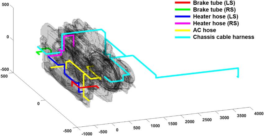
Journal of Computational Design and Engineering, 2021, 8(4), 1098–1114               1105

Table 2: Location data of terminals and intermediate points (Kim et al., 2021).

    No.                                Routing component                                 Type                                Location data

                                                                                           T1                              (−740, −290, −60)
     1                                   Brake tube (LS)                                   I1                                (−740, −450, 10)
                                                                                           T2                                (−280, −450, 10)
                                                                                           T1                               (−670, 280, −60)
                                                                                           I1                              (−500, 700, −100)
     2                                   Brake tube (RS)
                                                                                           I2                              (−100, 600, −100)
                                                                                           T2                              (−240, 330, −100)
                                                                                           T1                                (−905, 7.5, 160)
     3                                   Heater hose (LS)                                  I1                             (−905, −330, −115)
                                                                                           T2                             (−555, −330, −115)
                                                                                           T1                                  (−877, 34,160)
                                                                                           I1                                 (−877, 34, 450)

                                                                                                                                                   Downloaded from https://academic.oup.com/jcde/article/8/4/1098/6316573 by guest on 21 October 2021
     4                                  Heater hose (RS)
                                                                                           I2                                  (−155, 0, 450)
                                                                                           T2                                  (−155, 0, 260)
                                                                                           T1                                 (−935, −52, 40)
                                                                                           I1                              (−935, −410, −40)
     5                                       AC hose                                       T2                             (−490, −410, −210)
                                                                                           I2                                   (60, −410, 60)
                                                                                           T3                                  (60, −190, 113)
                                                                                           T1                                (−884, 196, 160)
                                                                                           I1                              (−884, −203, 160)
                                                                                           T2                                (312, −203, −40)
     6                                Chassis cable harness
                                                                                           I2                             (1330, −203, −202)
                                                                                           T3                               (1330, 345, −202)
                                                                                           T4                             (3900, −350, −135)

considering branch routing is adopted. Because the basic MA                the backtracking process until the backtracking path encounters
and GA are described in previous studies, they are only briefly            an obstacle or the next neighboring cell is labelled with a higher
explained in this section. The MA, which is also called Lee’s al-          value than the current cell. Figure 10c illustrates how the prior-
gorithm, finds a possible routing solution based on a breadth-             ity direction works in the modified MA. These two strategies can
first search. It always provides an optimal solution if one exists.        be compared with the basic MA, as shown in Fig. 10a.
The green and yellow cells in Fig. 9a represent the terminals and              Although the modified MA finds a better routing solution
obstacles, respectively, whereas the blue cells represent the de-          than the MA does, it does not always provide the best routing
sign domain. This algorithm consists of two steps: wave prop-              path because randomness is still inherent in the backtracking
agation and backtracking. The wave propagation consecutively               process. As the design domain increases, the probability of find-
labels the neighboring cells from the starting point to the goal           ing a good routing solution decreases drastically. The GA, which
point. When the wave propagation is completed, each cell is la-            is one of the most popular heuristic optimization algorithms,
belled with a value, as shown in Fig. 9b. The backtracking process         has been adopted to find a better routing solution. Four core el-
starts from the goal point and moves to a neighboring cell with            ements of the GA should be defined to solve routing problems:
a lower value. As this process randomly chooses the direction of           (1) route chromosome, (2) initial population, (3) fitness function,
backtracking, the MA provides multiple solutions. Random se-               and (4) genetic operators. A route chromosome, which repre-
lection in the backtracking process increases the diversity of so-         sents a routing path, consists of a series of neighboring cells
lutions, but it also increases the number of bends in the routing          from the starting point to the goal point. The information of
solution, as illustrated in Fig. 9b. In addition, the search area is       each cell includes the x-, y-, and z-coordinates of its center point.
limited to within the rectangular (2D problem) or cuboidal shape           The initial population of the GA is generated by the MA to main-
(3D problem) of the design domain determined by the locations              tain a high level of diversity in the routing solutions. The fit-
of the two terminals. Thus, the routes cannot deviate away from            ness function, which is a criterion for evolving and updating
the obstacles when they block all paths from the starting point            the initial population, is the objective function for design opti-
to the goal point in the search area.                                      mization. The total length of the route or the number of bends
    A modified MA has been developed to overcome the disad-                is usually selected as a fitness function. There are two typical
vantages of MA (Niu et al., 2016; Sui & Niu, 2016). In the modified        genetic operators: mutation and crossover. A two-point muta-
MA, two strategies are adopted: the auxiliary point and the prior-         tion and crossover are used in the GA for routing problems. In
ity direction. The routing solution from the modified MA passes            the two-point mutation procedure, a route chromosome, called
through the auxiliary point. This point plays an important role            the “parent chromosome,” is randomly selected, and two nodes
when a specific area needs to be searched, and it enables the              on this chromosome are randomly chosen. A midpath between
identification of a routing path outside the search area of the            these two cells is generated using the modified MA and inserted
MA. Figure 10b illustrates how an auxiliary point works in the             into the chromosome. The evolved chromosome is called the
modified MA. The priority direction modifies the backtracking              “child chromosome.” Figure 11 shows an example of how the
process of the MA. As the bending deteriorates the quality of              two-point mutation works in the GA. In a two-point crossover,
the routing solution, the path direction does not change during            two route chromosomes are randomly selected from the popula-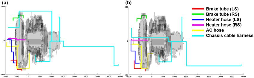
1106       Automatic routing design system for commercial trucks

                                                                                                                                                     Downloaded from https://academic.oup.com/jcde/article/8/4/1098/6316573 by guest on 21 October 2021

Figure 7: Flowchart of the routing algorithm incorporated in the design support module.

tion, and a crossover node is randomly chosen from each chro-                       evolve into better routing solutions by minimizing the fitness
mosome. A midpath between these two cells is generated us-                          function.
ing the modified MA and inserted into each chromosome. Fig-                            The GA, which is combined with the modified MA, can
ure 12 shows how the two-point crossover operates in the GA.                        deal with routing problems with two terminals. However, this
Based on these genetic operators, the routes in the population                      algorithm cannot be adopted when there are more than two ter-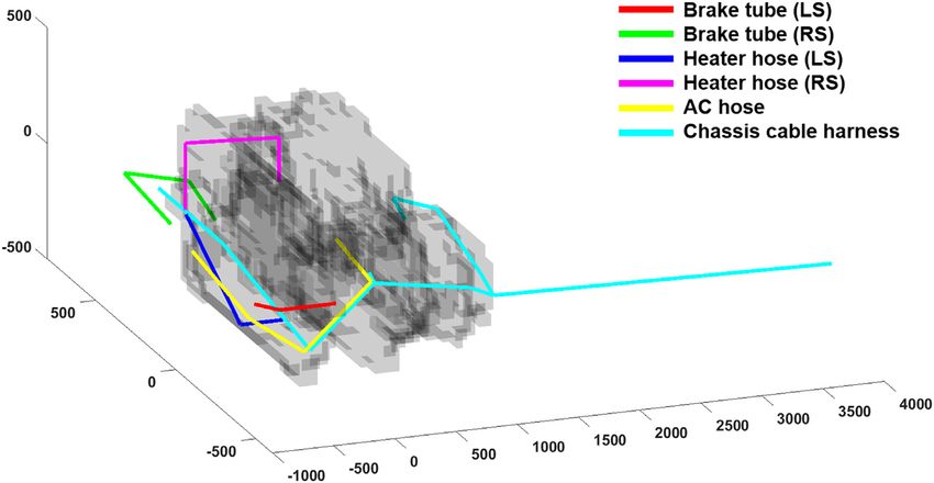
Journal of Computational Design and Engineering, 2021, 8(4), 1098–1114             1107

                                                                                                                                                         Downloaded from https://academic.oup.com/jcde/article/8/4/1098/6316573 by guest on 21 October 2021
Figure 8: Example of the routing algorithm incorporated in the design support module.

Figure 9: MA: (a) routing problem and (b) multiple solutions.

minals. The modified GA, which deals with branches, was pro-                       minal at each branch is selected as the CSP. After determining
posed to solve this type of routing problem (Sui & Niu, 2016).                     the CSP, the initial routing path between the CSP and the termi-
In the modified GA, the route chromosome consists of branch                        nal at each branch is determined by the modified GA. The fitness
routes that connect a terminal and a common starting point                         function is defined as the weighted sum of the total length of the
(CSP). Figure 13 illustrates m chromosomes in a population for                     route and the total number of bends in the route as follows:
a routing problem with n terminals. All branches are connected
at the CSP. In the initial population, the point that minimizes the
sum of the Euclidean distance between this point and each ter-                                         f (x) = w1 l (x) + w2 b (x) ,               (1)
1108 Automatic routing design system for commercial trucks
Downloaded from https://academic.oup.com/jcde/article/8/4/1098/6316573 by guest on 21 October 2021
Figure 10: Modified MA: (a) without auxiliary point and priority direction, (b) with an auxiliary point, and (c) with priority direction.
Figure 11: Two-point mutation operation in the GA.
Figure 12: Two-point crossover operation in the GA.
Figure 13: Chromosome of the modified GA.
where f is the fitness function, the components of vector x in Figs 14 and 15, respectively. The whole crossover, which is
are coordinates of the cells in the route, l is the total length of shown in Fig. 16, randomly chooses two parent chromosomes
the route, b is the number of bends in the route, and w1 and and switches the route of the corresponding branches.
w2 are the weight or normalization factors. There are three ge- Although the conventional modified GA provides various ref-
netic operators: two-point mutation, two-point crossover, and erence routing layout designs for validation, they are far from
whole crossover. In the modified GA, the two-point mutation practical solutions because their routes pass through the open
and crossover are identical, but they are consecutively carried design space. This leads to an increase in assembly and produc-
out between the corresponding branches. The two-point mu- tion cost in engineering problems. Maintaining routes as close
tation and crossover operations in the modified GA are shown as possible to obstacles is called the clamping condition. To re-Journal of Computational Design and Engineering, 2021, 8(4), 1098–1114 1109
Downloaded from https://academic.oup.com/jcde/article/8/4/1098/6316573 by guest on 21 October 2021
Figure 14: Two-point mutation operation in the modified GA.
Figure 15: Two-point crossover operation in the modified GA.
Figure 16: Whole crossover operation in the modified GA.
solve this issue, a new fitness function is proposed to consider route, b is the number of bends in the route, d is the shortest dis-
the condition of the tubes, hoses, and cable harnesses in the al- tance between each cell in the route and the closest obstacle, nc
gorithm. In this study, the fitness function was defined as fol- is the number of cells in the route, and w1 , w2 , and w3 are the nor-
lows: malization factors. The score map that considers the shortest
nc distance between each cell in the design domain and the clos-
f (x) = w1 l (x) + w2 b (x) + w3 d (xi ) , (2) est obstacle of an example with four goal points or terminals is
i =1 shown in Fig. 17. As this score is minimized using the routing
where f is the fitness function, the components of vector x are algorithm, the routes are located near the obstacles that satisfy
coordinates of the cells in the route, l is the total length of the the clamping condition. In this study, the weight factors are de-1110 Automatic routing design system for commercial trucks
The reference routing layout design from this algorithm may not
be directly comparable to the routing results because it is ob-
tained in a different design domain, and the route is always bent
orthogonally. This design usually provides longer and more con-
servative routes than the routing results because of the clamp-
ing condition. However, the proposed algorithm provides an ex-
cellent reference routing layout design during the vehicle devel-
opment process.
5. Application Results
The proposed automatic design system for generating a rout-
ing layout was applied to a commercial truck. Our collaborators
in the industry provided a CAD model of the vehicle. The tar-
Downloaded from https://academic.oup.com/jcde/article/8/4/1098/6316573 by guest on 21 October 2021
geted routing components were carefully determined based on
intensive discussions with the designers. In this study, six rout-
ing components were selected, and their priority order was de-
termined as follows: brake tube (LS) and (RS), heater hose (LS)
and (RS), AC hose, and chassis cable harness. The brake tubes
and heater hoses had two terminals. The AC hose had three ter-
minals, whereas the chassis cable harness had four terminals.
First, a model simplification of the targeted vehicle was per-
Figure 17: Example of the shortest distance between each cell in the design do-
formed. As the routing components were located near the front
main and the closest obstacle in a routing problem.
of the vehicle, only three critical parts were included in the de-
sign domain as obstacles: the cooling module, engine, and trans-
mission. Figure 19 shows the model simplification of these parts
using a grain size of 50 mm. The grain size was set to 50 mm for
the routing operation and 20 mm for generating the reference
layout design. The grain size was large in the graph-based rout-
ing algorithm to reduce computational time. The location co-
ordinates of the terminals and intermediate points, which are
listed in Table 2, were saved in an Excel file at the data layer in
the priority order from the first to sixth component. The inter-
mediate points were only considered in the graph-based rout-
ing algorithm. The model information consisted of vertices and
faces of the simplified model. The vertex was defined by x-, y-
, and z-coordinates, and all vertices were numbered. The face,
which is a triangular face in this model, was defined by the num-
bers associated with the three vertices. The vertex and face in-
formation of the simplified model was saved in the Excel file, as
shown in Fig. 20, and was then imported into MATLAB. The first
and second sheets in Fig. 20 list the x-, y-, and z-coordinates of
the vertices and the numbers of the three vertices of each face
of the cooling module. The third and fourth sheets and the fifth
and sixth sheets list those of the engine and transmission, re-
spectively.
After the data were imported into the system layer, the de-
veloped graph-based routing algorithm was applied. The rout-
ing layout design results are illustrated in Fig. 21 and listed in
Table 3. The routing algorithm was run using a workstation (In-
tel Core i7-4960X CPU, 3.60 GHz, 32GB RAM) with MATLAB 2020a.
The routes of all components were successfully obtained by this
module. The routing solutions of the brake tube (LS), heater hose
Figure 18: Flowchart of the routing algorithm incorporated in the design valida- (LS) and (RS), and AC hose were acceptable. The routing solu-
tion module. tion of the brake tube (RS) involved excessive deviation outside
the chassis frame because the CAD models of obstacles became
fined as w1 = 1/lg , w2 = 1/ max(b) , and w3 = 1/ max(d) , where larger during the model simplification procedure. Finally, the
lg is the grain size, and max(b) and max(d) are the maximum route of the chassis cable harness was also acceptable, except
values that appeared during the optimization, respectively. for the rear part of the route, which would have been reasonable
The default values in MATLAB were used as the parameters if it was located inside the chassis frame in the final routing lay-
for GA. out. Thus, the routes of the brake tube (RS) and chassis cable
A flowchart of the proposed algorithm, which generates a ref- harness had to be slightly redesigned in manual operation after
erence routing layout design for validation, is shown in Fig. 18. its geometric information was exported from MATLAB to CATIAJournal of Computational Design and Engineering, 2021, 8(4), 1098–1114 1111
Figure 19: Simplification of the vehicle model at the input layer.
Downloaded from https://academic.oup.com/jcde/article/8/4/1098/6316573 by guest on 21 October 2021
Figure 20: Model information in Excel at the data layer.
Figure 21: Routing layout design from the design support module.
Table 3: Numerical results of routing layout design.
Total length (mm)
Reference routing layout design
Routing component Routing layout design
Proposed algorithm Conventional algorithm
Brake tube (LS) 634.6 740 740
Brake tube (RS) 1171.2 620 640
Heater hose (LS) 785.3 1000 1000
Heater hose (RS) 1252.8 1260 1240
AC hose 1682.1 2240 2260
Chassis cable harness 6857.3 7880 80201112 Automatic routing design system for commercial trucks
Downloaded from https://academic.oup.com/jcde/article/8/4/1098/6316573 by guest on 21 October 2021
Figure 22: Reference routing layout design from the conventional cell-based routing algorithm.
Figure 23: Reference routing layout design from the proposed cell-based routing algorithm in the design validation module.
in the output layer. The routing results were compared with the tubes, heater hoses, and AC hose were generally in good agree-
current routing design in our previous work (Kim et al., 2021). ment with the reference layout, and the route of the chassis
In general, however, a reference routing layout design does not cable harness was generated on the left-hand side of the ve-
exist during the vehicle development process. hicle, but it passed over the engine in the reference layout. In
In this study, the proposed cell-based routing algorithm for a the graph-based routing algorithm, the intermediate guided this
generating reference routing layout design was compared with route to the left-hand side of the vehicle. As the intermediate
the conventional algorithm, and the routing solution from the points were not used in the proposed cell-based routing algo-
design support module was validated using the reference rout- rithm to provide a greater degree of freedom, it found the short-
ing layout design. The routing results from the conventional and est path above the engine. The total length of the route for each
proposed cell-based routing algorithms based on the modified component from the design support module was shorter than
GA and MA are shown in Figs 22 and 23, respectively. The numer- that from the reference routing layout, except for the brake tube
ical results of these algorithms are listed in Table 3. Although (RS). The total lengths of the brake tube (LS), heater hose (LS)
there are some minor differences in the total length of some and (RS), AC hose were approximately 14.24%, 21.47%, 0.57%,
routing components, the two algorithms provided similar re- and 24.90%, respectively, shorter than the corresponding refer-
sults, except for the chassis cable harness. The differences in ence length. The total length of the chassis harness cable could
their routes are shown in Fig. 24. As the conventional routing vary slightly depending on the vehicular components behind the
algorithm does not consider the clamping condition, the rout- transmission, but it showed that the length was approximately
ing path of the chassis cable harness is located far from the ob- 11.86% shorter than the reference length. The routes of the brake
stacles, as shown in Fig. 24a. However, this is not a realistic op- tube (RS) heavily deviated outside the vehicular frame compared
tion as it increases unnecessary assembly and production cost. to those of the reference routing layout. The route of the brake
On the other hand, as the proposed routing algorithm considers tube (RS) was approximately 88.90% longer than that of the ref-
the clamping condition, it provided routes with higher quality, erence routing layout. This is because the graph could not find
which are located near the obstacles, as shown in Fig. 24b. the routing path based on the generated vertices. This issue can
Finally, the routing results from the design support mod- be solved by the final manual operation of the designers in the
ule were compared with the reference routing layout design output layer. The final routing layout design of the application,
from the proposed routing algorithm. The results from the brake however, is not included in this study because it is confidentialJournal of Computational Design and Engineering, 2021, 8(4), 1098–1114 1113
Downloaded from https://academic.oup.com/jcde/article/8/4/1098/6316573 by guest on 21 October 2021
Figure 24: Reference routing layout design: (a) conventional algorithm and (b) proposed algorithm.
information that belongs to the sponsoring company. However, sembly, production, and installation costs. Routing components
the authors believe that the results of this application demon- such as tubes, hoses, and cable harnesses have their own char-
strated the effectiveness and high potential of the proposed au- acteristics. The bending radius and electromagnetic compati-
tomatic design system for generating routing layout design and bility, for instance, are important factors in the routing layout
showed that it worked successfully for an industrial problem. design of wiring harnesses. The routing algorithms proposed
in this study find the shortest routing path but cannot reflect
the characteristics of each component. Because of the variety
6. Discussion and Conclusions of routing algorithms and the absence of benchmark problems,
a comparative study between routing algorithms was not done.
The routing layout design of vehicular components is one of the
The models of the obstacles were also simplified to reduce the
most demanding and challenging areas across industries. Al-
computational time of the routing algorithms. This simplifica-
though many studies have been carried out in other industries to
tion may lead to a deterioration in the accuracy of the rout-
resolve this issue, only a few studies have been conducted in the
ing results. Therefore, some manual operations were required
automobile industry. The demand for an automatic virtual de-
to obtain the final routing layout design in the last step. De-
sign system for vehicular routing components is increasing be-
spite these limitations, the authors believe that this study is a
cause of the COVID-19 pandemic. Many automotive manufactur-
unique attempt, which suggests an automatic design system for
ers have recently suffered problems in the design, assembly, and
solving routing problems in the automobile industry that signif-
production processes, primarily because of the shortage in the
icantly contributes to improving the design, assembly, and pro-
supply of routing components and their prototypes, as well as
duction process of commercial trucks. In future work, the afore-
changes in the working environment. Hence, conventional de-
mentioned issues will be considered in developing the routing
sign methodologies based on know-how and trial and error are
algorithm for each vehicular routing component. An intensive
no longer favored.
comparison study of the existing design approaches and routing
In this study, we constructed an automatic design system for
algorithms will also be conducted to select the best algorithm
generating a routing layout that significantly improved the man-
in accordance with the characteristics of routing problems. In
ual routing operation of the designers and engineers. It mini-
addition, the problem of the missing benchmark, which is very
mized the interactions between design teams and made it pos-
important for comparing the efficiency and accuracy of the de-
sible to design a routing layout without frequent route changes
veloped algorithms, will be studied.
and trial and error using the CAD software. The authors of this
paper, who are from both academia and industry, collaborated
closely to propose a new automatic design system. The charac- Acknowledgment
teristics of the routing problem were dealt with in several steps,
and the functional requirements for the design system, which The first five authors greatly appreciate the support of this work
were determined by practitioners in the automobile industry, by the Hyundai Motor Company. Such support does not consti-
were satisfied. An engineering routing problem of a commer- tute an endorsement by the sponsor of the opinions expressed
cial truck was solved to demonstrate the effectiveness of the in this article.
proposed automatic design system. The sequential graph-based
routing algorithm of the design support module provided a sat-
isfactory routing layout solution for each routing component. To Conflict of interest statement
generate a reference routing layout design, a cell-based routing None declared.
algorithm based on the modified GA and MA was adopted. A
comparison between the proposed and conventional algorithms
was also performed. It was demonstrated that the proposed al- References
gorithm provides a better reference layout design than the con- Asmara, A. (2013). Pipe routing framework for detailed ship design.
ventional one. TUD Technische Universiteit Delft (Delft: VSSD).
The authors acknowledge that the proposed automatic de- Black C. (2017). 1990’s prototype marine variant of the Cummins
sign system has several limitations. For example, it disregards QSKV60 industrial diesel engine. Grabcad Community. https:
some aspects of the routing layout design problem, e.g. as- //grabcad.com. (Accessed on 11.5.2018).You can also read