Installation and Operation Manual - AllSync IQ Wired Master Clock - Part # H004658 - American Time
←
→
Page content transcription
If your browser does not render page correctly, please read the page content below

Installation and Operation Manual

     AllSync IQ® Wired Master Clock

                                      Part # H004658
                                      Rev. 8
                                      February 2021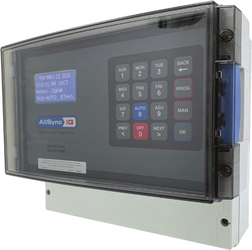
FCC Conformity                       (USA only)                                                     AllSync IQ Installation Manual
Responsible Party: American Time, 140 3rd St. S., PO Box 707, Dassel, MN 55325-0707 USA
TEL: 320-275-2101, declares that the product(s):
AllSync IQ Master
Comply with Part 15 of the FCC Rules. Operation is subject to the following two conditions:
      (1) This device may not cause harmful interference
      (2) This device must accept any interference received, including interference that may cause undesired operation
This equipment has been tested and found to comply with the limits for a Class B digital device, pursuant to Part 15 of the FCC Rules.
These limits are designed to provide reasonable protection against harmful interference in a residential installation.

Safety Precautions
All electrical power and signal wiring connected to the AllSync IQ Master, secondary clocks and signaling devices must be installed by
qualified persons in conformance with applicable national and local electrical codes. Improper installation of this equipment can result
in lethal electrical shock and fire.
Disconnect and lock out electrical power to the unit before removing the wiring compartment cover.
Voltage applied to clock and signal relay contacts must not exceed 250vac.
The AllSync IQ Master should be installed in a secure location protected from:
       • Physical damage
       • Water, including condensation
       • Direct sunlight
       • Operation by untrained personnel

                                                           American Time
                                                  140 3rd Street South, PO Box 707
                                                      Dassel, MN 55325-0707

                                                        Phone: 800-328-8996
                                                         Fax: 800-789-1882

                                                         american-time.com

2                                                                                                                       © American Time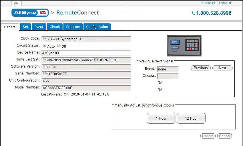
AllSync IQ Installation Manual                                                                                                             Table of Contents
Introduction
                   AllSync IQ Features................................................................................................................................................ 4
Installation/Programming Instructions for AllSync IQ
                   AllSync IQ Installation............................................................................................................................................. 5
                   AllSync IQ Setup Wizard..................................................................................................................................... 6-9
                   Ethernet Installation......................................................................................................................................... 10-11
                   Wired Clock Circuit Installation.............................................................................................................................. 12
                   Adjust Time Menu................................................................................................................................................. 13
                   Wired Signal Circuit Installation........................................................................................................................14-23
                   Remote Connect Web Interface........................................................................................................................24-31
                   Settings & Configurations:
		                                  Manually Set Time and Date................................................................................................................ 32
		                                  Manage Locks.....................................................................................................................................33
		                                  Time Sync Priority...............................................................................................................................33
		                                  Clock Code..........................................................................................................................................33
		Clear/Restore......................................................................................................................................33
		                                  Setup Manager....................................................................................................................................34
		                                  Banner Text.........................................................................................................................................34
		                                  Display Settings...................................................................................................................................34
		                                  Auto DST Settings...............................................................................................................................34
		                                  USB Flash Drive...................................................................................................................................34
Troubleshooting
                   AllSync IQ.............................................................................................................................................................35
                   Ethernet...............................................................................................................................................................36
                   Remote Connect................................................................................................................................................... 37
                   Wired Clock Circuit...............................................................................................................................................38
                   Wired Signal Circuit.............................................................................................................................................. 39
                   Secondary Clocks.................................................................................................................................................40
Appendix A: Ethernet Timekeeping - Known Good Internet Time Servers.................................................................................. 41
Appendix B: Supported Time Zones.......................................................................................................................................... 42
Appendix C: Tone Generator Wiring..........................................................................................................................................43
Appendix D: Wired Signal Circuit Programming Examples................................................................................................... 44-46
Appendix E: Checking AllSync IQ Master Status Information..................................................................................................... 47
Appendix F: Port Diagram........................................................................................................................................................48
Appendix G: Maintenance Guide............................................................................................................................................... 49
Appendix H: Clock Circuit Wiring Diagrams......................................................................................................................... 50-54
Appendix I: Clock Codes................................................................................................................................................... 55-57
Glossary.......................................................................................................................................................................................58

© American Time                                                                                                                                                                                     3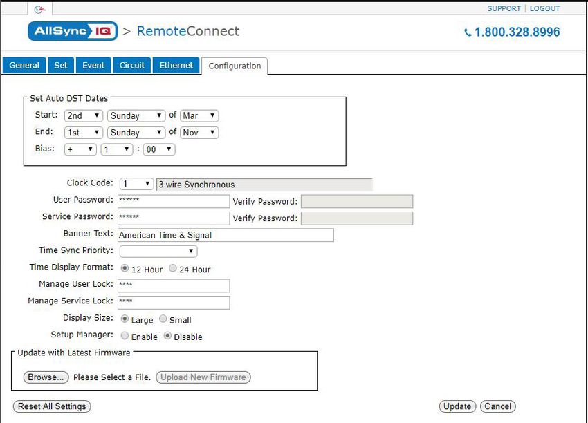
Introduction                                                                                    AllSync IQ Installation Manual

                      The AllSync IQ master provides synchronized control of secondary system clocks and electrical circuits
                      such as those for controlling signaling devices and lights.
Introduction

                      Standard features of the AllSync IQ master include:
                          • Built-in keypad and LCD for setup and operation
                          • Internal clock accuracy of ±1 minutes per year (without synchronization)
                          • User selectable clock codes for controlling a wide range of clock types
                          • Two level password security
                          • Manual advance of impulse clock types
                          • Automatic Daylight Saving Time and Leap Year correction
                          • Programmable Custom and Automatic Daylight Saving Time
                          • Automatic time synchronization with Ethernet
Installation

                          • Remote setup and operation with web browser interface via Ethernet
                      Optional features include:
                          • Flexible control of 6 signal circuits and/or 1 set of clock circuits
                          • Manual control of signal circuits
                      The following table shows the relay options included with each model number.
Troubleshooting

                                                    Model No.                  1 Clock Circuit (2 Signal Circuits (6
                                                                                    Relays)           Relays)
                                                    ASQMSTR-00X8E                      X                  X
Appendix
Glossary

                  4                                                                                                                © American Time
AllSync IQ Installation Manual                                                                             Installation

Electrical Connections

                                                                                                                              Introduction
120vac Supply Connections
WARNING
To prevent electrical shock, do not apply electrical power to the master, clock relays or signal relays before
completing all wiring connections.
Connect the ungrounded (hot) wire to the H screw terminal, the neutral wire to the N terminal and the ground wire to
the    terminal
Fuse
A 2.5A - 240vac subminiature (Little Fuse Inc. part #37412500410 recommended) protects the power input circuit.

                                                                                                                              Installation
Each clock and signal relay circuit must be current limited to 8A or less by an external circuit breaker or fuse.
Clock Connections
CAUTION
To prevent damage to relays, relay contact voltage must not exceed 240vac.
WARNING
To protect against shorts between power and signal circuits, all wires connected to the power, clock, and
signal circuit terminals must be insulated to 300vac.

                                                                                                                              Troubleshooting
Appendix I shows wiring connections to the master clock and the secondary clocks for all clock types controlled by
the AllSync IQ master.

Mounting Master Clock
The AllSync IQ master clock should be:
    •   Located indoors in a dry location

                                                                                                                              Appendix
    •   Mounted upright on a vertical surface
    •   Protected from physical damage
    •   Protected from water, including condensation
    •   Out of direct sunlight
    •   Operated by trained personnel
An area at least 22" wide and 201/2" high should be reserved to allow a clearance of at least 12" below and on left
side of the AllSync IQ master. Wiring for power, clock and signal circuits must enter through conduit knockouts along
the bottom of the enclosure. Connector for Ethernet and power switch are are located on the left side of the enclosure.

                                                                                                                              Glossary
The AllSync IQ master is designed to be wall-mounted by a keyhole hanger and screws. The Quick Start Guide shows
a template for locating wall hangers to mate with these openings.

© American Time                                                                                                           5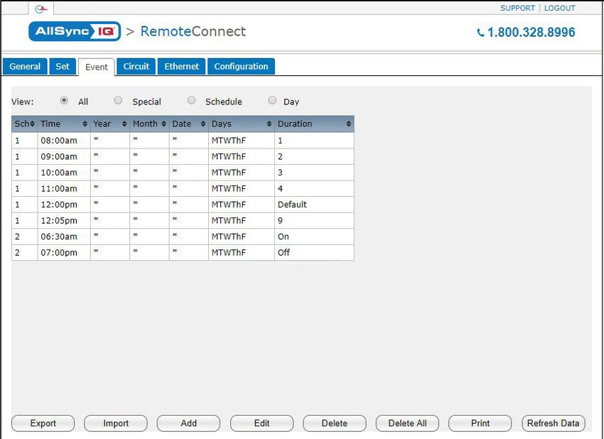
AllSync IQ Setup Wizard                                                                1:49
                                                                                                         FRI OCT 3 2014
                                                                                                                            :45
                                                                                                                            AM    AllSync IQ Installation Manual
                                                                                                            American Time
                                                                                                            800-328-8996

                      Programming Procedure
Introduction

                      Turn on the power to the AllSync IQ                                                Setup Wizard Main Screen
                      The first time the unit is powered up, it will prompt you (See Setup Wizard Main
                      Screen) to press:                                                                              Setup Wizard
                                                                                                                     1=Enter Now
                          1 To use the Setup Wizard
                                                                                                                     2=Bypass
                          2 Bypass the Setup Wizard temporarily                                                      3=Disable
                          3 Disable the Setup Wizard
                      nNote: Bypass 2 or Disable 3 will exit Setup Wizard.
Installation

                      uTo Configure the AllSync IQ                                                       1
                      •   Press: 1, and enter 4 digit User Lock or 				                                              Config Menu
                          enter 0000 to disable this feature.                                                        Choose User Lock:
                          User Lock                                                                                         xxxx
                      nNote: User Lock is the security level used for accessing time/date                            0000=Disab       OK=Done
Troubleshooting

                      and event menus.                                                                   2
                      •    Press O                                                                                   Config Menu
                                                                                                                     Choose Service Lock:
                                                                                                                            xxxx
                      v Enter 4 digit Service Lock or enter 0000 to disable this 		                                  0000=Disab       OK=Done
                      feature.
                      • Service Lock:                                                                    3
                      nNote: Service Lock is the security level used for accessing                                   Set Menu LOCAL
                                                                                                                     Time Zone Code:  05
                      System Controller configuration menus.                                                         99=Custom     USCT
                      • Press O                                                                                      =Scroll     OK=Accept
Appendix

                      w Select local time zone by using the  keys or enter a
                      time code from Appendix B. Press O and skip to y.
                                                                                                         4
                      If a custom time zone is needed, press 99 and O and
                                                                                                                     Set Menu Bias LOCAL
                      continue to x.                                                                                 Enter Time Zone
                                                                                                                     offset from UTC
                      xEnter offset from UTC for Custom Time Zone.                                                   + 11:30         OK=Accept
                           Use  to change + to -.
Glossary

                      •
                      •    Press O

                                                                                                         5
                      ySelect Daylight Saving Time (DST) option.                                                     Set Menu DST - LOCAL
                      • Option 8 causes automatic time changes to and from 			                                       Set DST   (AUTO)
                      DST under the changeover dates currently in effect in the 			                                  8=Auto    9=Custom
                      USA at the time of system manufacture.                                                         0=Off     OK=Accept
                          Press O and skip to 14.
                      • Option 9 allows a custom DST to be entered. Press
                      O and skip to z.
                      • Option 0 turns off DST. Press O and skip to 14 .

                          STOP                                          y, skip to 14 .
                                              If you chose Auto or Off in
                                              If you chose Custom, continue to z.

                  6                                                                                                                                © American Time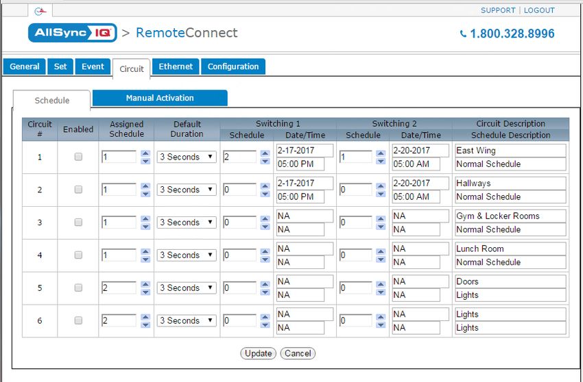
AllSync IQ Installation Manual 1:49
FRI OCT 3 2014
:45
AM
AllSync IQ Setup Wizard
American Time
800-328-8996
Programming Procedure (cont)
Introduction
For use only when configuring Custom DST settings
zDefine DST: 6
• Press 1 to set fixed dates and times for the beginning Set Menu DST - LOCAL
Define DST By:
and end of DST. Skip to .
1= Fixed Dates
• Press 2 to set months, weeks, weekdays and times 2=Floating Dates
(floating dates) for the beginning and end of DST.
Installation
Select fixed dates for DST (START): 7
Set Menu DST - LOCAL
• Use to scroll start month and day. Press O DST Start: Mar 30
to move to the next field. Start Time: 01:00 AM
• Use or keypad to enter the start time. Press O = AM/PM OK=ACPT
to move to the next field.
• Use to select AM/PM. Press O to accept.
8
Set Menu DST - LOCAL
Troubleshooting
Select fixed dates for DST (END): DST End: SEP 15
• Use to scroll end month and day. Press End Time: 02:00 AM
O to move to the next field. = AM/PM OK=ACPT
• Use or keypad to enter the end time. Press
O to move to the next field.
• Use to select AM/PM. Press O to accept.
9
Set Menu DST - LOCAL
DST Bias: +00:00
Select fixed dates for DST (BIAS):
• Use keypad to enter bias. = +/- OK=ACPT
Appendix
• Use to select "+" or "-". Press O to accept.
10
Select floating dates for DST (START DATE) Set Menu DST - LOCAL
• Use to scroll week, day and month. Press Start of DST:
2nd SUN of MAR
O to move to the next field.
Bias +1:00 OK=ACPT
• Use on the bias selection to change + and -.
• Use keypad to enter bias. Press O to accept. 11
Set Menu DST - LOCAL
Glossary
11 Select floating dates for DST (START TIME):
Start Time:
01:00 AM
• Use or keypad to enter the start time. = AM/PM OK=ACPT
• Press O to accept.
12
12 Select floating dates for DST (END DATE)
Set Menu DST - LOCAL
• Use to scroll week, day and month. Press O End of DST:
to move to the next field. Press O to accept. 1st SUN of NOV
OK=ACPT
13 Select floating dates for DST (END TIME)
13
• Use to enter the start time. Press O Set Menu DST - LOCAL
to move to the next field. End Time:
• Use to select AM/PM. Press O to accept. 01:00 AM
= AM/PM OK=ACPT
© American Time 7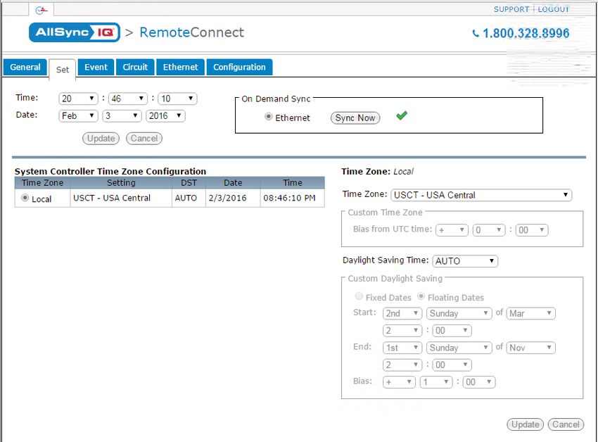
AllSync IQ Setup Wizard                                                               1:49
                                                                                                        FRI OCT 3 2014
                                                                                                                           :45
                                                                                                                           AM            AllSync IQ Installation Manual
                                                                                                           American Time
                                                                                                           800-328-8996

                      Programming Procedure (cont)
                                                                                                             14
Introduction

                      14    To set the time display mode for the AllSync IQ, select 12/24 Hr Mode.                               Set Menu 12/24 Mode
                       •    Press 1 for 12 hour mode-AM/PM (1:00 PM)                                                             Choose Mode: 1
                       •    Press 2 for 24 hour mode-Military (13:00)                                                            1=12 HR (AM/PM)
                                                                                                                                 2=24 HR (Military)
                      15 Use the keypad to Enable DHCP or Disable to select static IP entry.
                       • Press 1 for enable DHCP
                                                                                                             15
                       • Press 2 for disable DHCP                                                                                Comm Menu
                                                                                                                                 DHCP
                       • Press O to accept
Installation

                                                                                                                                 1=Enable
                       If you chose enable, skip to 20                                                                           2=Disable		         Ok=Done
                       If you chose disable continue to 16
                                                                                                             16
                      16 Use the keypad to enter the Unit IP Address. This is a static address                                   Comm Menu
                                                                                                                                 Unit IP Address
                      assigned by your Network Administrator. Enter preceding zeros as necessary.                                    192.168.001.001
                      •     Unit IP Address: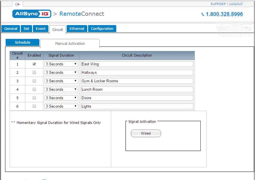
AllSync IQ Installation Manual               1:49
                                              FRI OCT 3 2014
                                                                 :45
                                                                 AM
                                                                                     AllSync IQ Setup Wizard
                                                 American Time
                                                 800-328-8996

Programming Procedure (cont)

                                                                                                                            Introduction
                                                                                    22
22 Use the keypad to enter the Alternate Time Server address. Enter preceding
                                                                                         Comm Menu
zeros as necessary.
                                                                                         Alt Time Srvr Addr
•       Alt. Time Server Address:                                                               173.014.055.009
•       Press O
Ethernet Option 1:49
FRI OCT 3 2014
:45
AM AllSync IQ Installation Manual
American Time
800-328-8996
Connecting Ethernet Option
Introduction
This option provides time synchronization via Simple Network Time Protocol (SNTP) or Daytime Protocol from Internet Time Servers or an
internal Network Time Server.
Configuration 1: Receive Time Sync via the Internet
(SNTP or Daytime Protocol)
Computers on the Local Area Network
Installation
AllSync IQ Master
1:49
:45
AM
FRI OCT 3 2014
American Time
800-328-8996
Troubleshooting
Local Area Gateway Firewall with Port
Ethernet Option requires: Inside the facility Network Server 123 or 13 open
Outside the
1. TCP/IP Network with Internet access or connection to a facility
Network Time Server.
Public
2. Cat 5 or above patch cable (not included). Internet
3. Host Name: asiq**
Time server on the
Internet supporting SNTP
Appendix
nNote: **Record the last 6 digits of device serial number (located or Daytime Protocol
on the side of the AllSync IQ master). The Host name can be used
to identify the AllSync IQ master on the network for DHCP.
nNote: The default ethernet settling has DHCP enabled to
Configuration 2: Receive Time Sync via the Internal
automatically obtain an IP address from a DHCP server. If no Network (SNTP)
DHCP address is received, the device will default to 192.168.10.10.
Computers on the Local Area Network
4. *Unit IP Address from
AllSync IQ Master
Network Administrator:
Glossary
*Subnet Mask:
1:49
5.
:45
AM
FRI OCT 3 2014
American Time
800-328-8996
6. *Gateway IP Address:
*Not required if DHCP is Enabled
7. Port Number (defaulted to 80):
8. Time Server DNS Address:
9. Time Server Address:
10: Alternate Time Server Address: Time server on the
LAN supporting
Local Area SNTP Protocol
Inside the facility Network Server
See Appendix A for a list of Internet Time Server addresses (or use
Outside the facility
the address of a server on your local network)
nImportant Note: Time Servers provide time sync for UTC Time,
but do not set Time Zone or DST settings.
nNote: This option automatically syncs once per hour at a time
preset at the factory.
10 © American TimeAllSync IQ Installation Manual 1:49
FRI OCT 3 2014
:45
AM
Ethernet Option
American Time
800-328-8996
Programming Procedure-Keypad 1a
Introduction
nNote: These settings may already have been entered using the Startup Wizard. Comm Menu
Turn on the power to the AllSync IQ DHCP
1=Enable
u Configure Communication (Comm) Settings: 2=Disable Ok=Done
Press P, 7, 3 to access Comm Settings:
1b (example)
a. Use the keypad to Enable DHCP or Disable to select static IP entry.
• Press 1 for enable DHCP Comm Menu
Unit IP Address
• Press 2 for disable DHCP 192.168.001.001Wired Clock Circuit Option 1:49
FRI OCT 3 2014
:45
AM AllSync IQ Installation Manual
American Time
800-328-8996
Introduction
Programming Procedure-Keypad Continued 2b
v Sync System Controller with correct time & date: Set Menu Mode
Enter User Lock:
a. Press: P1, to Set Menu Mode. xxxx
b. Enter User Lock and press O. PROG=EXIT OK=ENTER
c. Press: 9, to sync the System Controller with
Ethernet. Press > until Ethernet option is chosen. 2c&d
d. Press 8 to sync with Ethernet. Set Menu Mode
Time Sync Option is
nNote: If "Ethernet Sync Successful" is displayed, press OBB to return to Available: Ethernet
Installation
Main Screen. 8=Sync now OK=Set
If "Ethernet Sync Failed" is displayed, reference the troubleshooting guide. 3
w The Ethernet sync option is now configured and will update the time on the TUE FEB 09 2008
System Controller automatically once each hour at a time preset at the factory. 10:30:06 AM USCT
nNote: When Ethernet synchronization is working, ETH=S will be displayed on the American Time
Circts=Auto ETH=S
screen in small text mode as shown in screen shot 3. If a synchronization attempt
fails, ETH=N will be displayed.
Troubleshooting
Wired Clock Circuit Installation
To install wired clock circuits: 1:49
:45
AM
FRI OCT 3 2014
1. Disconnect and lock out power to the AllSync IQ Master and any circuit wiring.
American Time
800-328-8996
2. Remove the terminal block cover from the AllSync IQ.
a. Remove screw from each side of the cover.
b. Lift the cover up off the unit.
Appendix
3. Route signal circuit wires into the wiring compartment of the AllSync IQ.
a. Remove knockout(s).
b. Use copper conductors only.
Glossary
c. Use strain relief connector fittings in the knockout holes to secure the wires.
d. Route the wires into the wiring compartment, leaving enough slack to make all connections to the relay terminals.
4. Connect clock wires to the circuit relay terminals
NO COM NC NO COM NC NO COM NO COM NO COM NO COM NO COM NO COM
H N
CLOCK 1 CLOCK 2 BELL 1 BELL 2 BELL 3 BELL 4 BELL 5 BELL 6
Clock Circuit Terminals
Clock Circuit Fuses Surge Supression
ON/OFF Switches
See Appendix H on Page 50 for Clock Circuit Wiring Diagram
12 © American TimeAllSync IQ Installation Manual 1:49
FRI OCT 3 2014
:45
AM
Adjust Time Menu
American Time
800-328-8996
The Adjust Time menu serves two functions:
Introduction
1. Manual correction of impulse secondary clocks, and
2. Simple synchronization of the AllSync IQ to an external time source.
2
u Press: 9 to access the Adjust Time Menu Adjust Time
v Press 1 to enter Adjust System Clocks Menu Choose:
w Press 1 to bring up the Calculated Adjust screen 1=Adjust System Clks
Enter the time shown on the secondary clocks (to the nearest 2=Ethernet Sync Now
minute). The time entered should be in 12 hour format as AM/PM 3
Installation
settings are irrelevant.
Adjust System Clocks
Press O. The time difference between the secondary clocks and
1=Calculated Adjust
the system controller is displayed. 2=Man. Adjust Impulse
Press OK to initiate automatic correction of the secondary clocks 0=Cancel
and return to the Adjust Time screen.
x Pressing 2 in the Adjust System Clocks menu (#3 at right) brings
3a
up the Manual Adjust screen. Calc Clock Adjust
Enter Time Shown
Press > repeatedly to correct impulse clocks manually. on secondary clocks
Troubleshooting
Press OK when finished to return to the Adjust Time menu. 00:00
y Pressing 2 in the Adjust Time screen (#2 above) causes the unit to 4
attempt synchronization with external time sources* in order of priority.
If successful, a message confirming this flashes before the Time Display Adjust System Clocks
Manual Adj. Impulsed
screen appears.
>=Advance Clocks
*The time sync priority can be configured. Reference Settings and (1 per min) OK=Done
Configuration on Page 33.
Appendix
Glossary
© American Time 13Wired Signal Circuit Option 1:49
FRI OCT 3 2014
:45
AM AllSync IQ Installation Manual
American Time
800-328-8996
Wired Signal Circuit Installation
To install wired signal circuits (for electrical device control including bells, tone generators, lights, etc.):
Introduction
1. Disconnect and lock out power to the AllSync IQ Master and any circuit wiring.
1:49
:45
AM
FRI OCT 3 2014
2. Remove the terminal block cover from the AllSync IQ.
a. Remove screws from each side of the cover.
American Time
800-328-8996
b. Lift the cover up off the unit.
3. Route signal circuit wires into the wiring compartment of the System Controller.
Installation
a. Remove knockout(s).
b. Use copper conductors only.
c. Use strain relief connector fittings in the knockout holes to secure the wires.
d. Route the wires into the wiring compartment, leaving enough slack to make all connections to the relay terminals.
4. Connect signal wires to the circuit relay terminals.
Troubleshooting
a. Route the power (feed) line of each circuit to the COM terminal of the desired circuit (1-6) being connected.
b. Route the switched (load) line of each circuit to the NO terminal of the desired circuit (1-6) being connected.
c. Label the wires for each circuit as desired.
nNote: The signal circuits are protected with surge suppression components. In some applications, this protection can cause
leakage current to trigger the output device(s) when the circuit is switched ON. In these cases, the surge protection switches
(see illustration below) can be moved to the OFF position. Contact American Time Technical Support at 800-328-8996 with
any questions.
Appendix
AllSync IQ Master Wiring Compartment Diagram
NO COM NC NO COM NC NO COM NO COM NO COM NO COM NO COM NO COM
H N
Glossary
CLOCK 1 CLOCK 2 BELL 1 BELL 2 BELL 3 BELL 4 BELL 5 BELL 6
BLACK
FUSED
POWER
SOURCE WHITE
= Bell
= Light
LOW VOLTAGE
DEVICES
STEP DOWN
TRANSFORMER
14 © American TimeAllSync IQ Installation Manual 1:49
FRI OCT 3 2014
:45
AM
Wired Signal Circuit Option
American Time
800-328-8996
Programming Events (Keypad Interface)
Introduction
The AllSync IQ Master contains 6 integrated signal relays. When configured, the Signal Circuit Option allows the System Controller
to be used for operating bells, tone generators, lighting circuits and other electrical equipment.
nNote: AllSync IQ masters with the Ethernet option can also be programmed via the Remote Connect web interface (see page 25).
Definitions:
An Event is programmed into the AllSync IQ master with time and date information, as well as a duration or a start/stop command.
For example, Event 0001 may be programmed to execute every Monday, Wednesday and Friday at 10:00 AM for 3 seconds. Each
event is assigned to a Schedule. The AllSync IQ Master can store up to 9,999 events. The event duration is programmable from
1 to 9 seconds and also allows for ON or OFF commands. Normal events are recurring weekday events. A Special Event contains
date information that is not specific to weekdays. For example, you can set a special event for the 4th day of every month, the 4th
day of every January or the 4th day of January in a specific year. You can also set a special event for every Thursday in January
Installation
or every Thursday in a specific year. A Schedule Change Event is entered in the same manner as a Special Event. A schedule
change event allows you to change from one schedule to another. This may be useful for changing from a normal schedule to a
holiday schedule.
A Schedule is a group of events. For example, a school might program Schedule 01 with 4 events for their morning Elementary
recess schedule. The AllSync IQ Master allows for 99 unique schedules, with any number of events in each (up to a maximum total
of 9,999 events). Schedules, with groups of events, are assigned to Circuits.
A Circuit is defined as one of the 6 relay outputs on the AllSync IQ Master. Each circuit can be assigned one schedule at a time. For
example, Schedule 01 with 4 events might be assigned to Circuit 1 and Schedule 03 with 10 events might be assigned to Circuit 2.
uProgramming New Events
Troubleshooting
1a&b
a. Press: P2, enter User Lock using the keypad and press O to Event Menu
enter the Event Menu. View Events by
1=Schedule/Event
b. Press: 1 to add an event. 2=Date/Tme 3=WKDY
c. Select the number of the schedule for the new event and press O.
1c
d. If any events have already been assigned to the selected schedule, the Event Menu
days and start time for the first event are displayed. Use the > key to Choose Schedule
move to the New Event screen. Press O to display the Select Sch=01 Select 1-99
OK=Accept
Appendix
Weekdays screen.
nNote: Press < on the first event to view the last event. Press > to move 1d
to the New Event Screen. Event Menu
e. To program event days, press 1through7 keys to add or remove Sch=10 Event=0000
2008-02-12 12:04 AM
days individually, or
M-Del OK-Edt
Press 8 to add weekdays (shown), 9 to add weekends, or
Press 0 for special events or schedule change events. This allows events to
1e
be defined by date(s). Please reference section 3 (Programming Special Select Weekdays:
8=M-F MTWTF
Glossary
Events) and 4 (Programming Schedule Change Events) for details.
9=S+S Key 1234567
Press O to accept the assigned days. 0=Spec/Sch OK=Accpt
vProgramming Recurring Events by Weekday
For a non-special event, this brings up the Event Time screen. 2a
To program start time:
Event menu
a. Use the number keys to enter the hour and minute. Press< for AM or Select event time:
> for PM. Press O to accept the event start time. Evt Time: 12:00 AM
MTWTF OK=Acpt
The Event Duration screen appears. To program event duration (1-9 seconds):
b. Press any number 1-9 to specify duration, or 2b
Press 0 to use the default duration(s) for the circuit(s) assigned to the Event menu
schedule, or Duration 0=Default
2 Sec (1-9, < or >)
Press > to latch assigned circuits on until a later event turns them off, or Off=< On=> OK=Set
Press < to turn off assigned circuits that were previously turned on.
Press O to accept event duration.
© American Time 15Wired Signal Circuit Option 1:49
FRI OCT 3 2014
:45
AM AllSync IQ Installation Manual
American Time
800-328-8996
vProgramming Recurring Events by Weekday (continued)
Introduction
The Choose Schedule screen reappears: 2c
c. Press O to accept the schedule number. Event Menu
Choose Schedule
d. The Event Saved screen briefly appears followed by the Select Event Sch=01 Select 1-99
Time screen. OK=Accept
e. If a new event is to be programmed with the same assigned schedule, 2d
days and duration as the previous event, Press 1. Enter only the start Event Menu
time of the new event and press O. Follow this procedure for all new Y=All M=All
Installation
MTWTF 05:03 AM
events sharing the same schedule, days and duration. Event 0000 Saved
To see a programming example, see Appendix D. 2e
Press the 2 key to exit this loop and return to the View Events screen at the Event Menu
top of the Event Menu. Enter Another Event:
1=Yes
2=No
wProgramming Special Events 2e
Troubleshooting
a. Press 0 in the Select Weekdays screen. Event Menu
Select event time:
b. Press 1 for special Event. Evt Time: 1:00 AM
c. Change the year if necessary or enter 0000 to indicate all years. Press MTWTF OK=Acpt
O bring up the Enter Event Month screen.
3a
d. To change the month, enter the number of the month as 2 digits. Enter
Select Weekdays:
00 to select all months. Press O to accept and bring up the Choose 8=M-F MTWTF
screen. 9=S+S Key 1234567
e. Press 1 to select a day of the month and bring up the Select Event 0=Special OK=Accept
Appendix
Date screen. 3b
f. Enter a 2-digit day of the month or 00 for all days and press O. Event Menu
1=Special Event
Pressing 2 in the Choose Screen (3e) brings up the Select Day screen.
2=Schedule Change
At this screen:
Press 1-7 keys to add or remove days individually, or
3c
Press 8 to add weekdays, 9 to add weekends. Event Menu
Press O to accept the assigned days. Enter Event Year
Year: 2008 All=0000
Glossary
OK=Accept
3d
Event Menu
Enter Event Month
Month=02 February
All=00 OK=Accept
3e
Event Menu
Choose:
1=Set Date (1-31)
2=Set Weekday(s)
3f
Event Menu
Select event date
Day of month= 15
All=00 OK=Accept
16 © American TimeAllSync IQ Installation Manual 1:49
FRI OCT 3 2014
:45
AM
Wired Signal Circuit Option
American Time
800-328-8996
wProgramming Special Events (continued)
Introduction
g. The Select Event Time screen appears. To program start time: 3g
Use the number keys to enter hour and minute. Event Menu
Select event time:
Press < for AM or > for PM.
Evt Time: 12:00 AM
Press O to accept the event start time. MTWTF OK=Acpt
The Event Duration screen appears. To program event duration (1-9 seconds):
3h
h. Press any number 1-9 to specify duration, or
Event Menu
Press 0 to use the default duration(s) for the circuit(s) assigned to the Duration 0=Default
Installation
schedule, or 2 Sec (1-9, )
Press > to latch assigned circuits on until a later event turns them off, or Off=< On=> OK=Set
Press < to turn off assigned circuits that were previously turned on. 3i
Press O to accept event duration. Event Menu
Choose Schedule
The Choose Schedule screen reappears: Sch=01 Select 1-99
i. Press O to accept the schedule number. OK=Accept
Troubleshooting
j. The Event Saved screen briefly appears followed by the Select Event 3j
Time screen. Event Menu
To see a programming example, see Appendix D. Y=All M=All
MTWTF 05:03 AM
Press B exit the Event Menu. Event 0000 Saved
Appendix
Glossary
© American Time 17Wired Signal Circuit Option 1:49
FRI OCT 3 2014
:45
AM AllSync IQ Installation Manual
American Time
800-328-8996
xProgramming Schedule Change Events 4a
Introduction
Select Weekdays:
a. Press 0 in the Select Weekdays screen. 8=M-F MTWTF
9=S+S Key 1234567
b. Press 2 for Schedule Change. 0=Special OK=Accept
c. Change the year if necessary or enter 0000 to indicate all years. Press
O bring up the Enter Event Month screen.
4b
Event Menu
d. To change the month, enter the number of the month as 2 digits. Enter 1=Special Event
00 to select all months. Press O to accept and bring up the Choose 2=Schedule Change
screen.
Installation
e. Press 1 to select a day of the month and bring up the Select Event 4c
Date screen. Event Menu
f. Enter a 2-digit day of the month or 00 for all days and press O. Enter Event Year
Year: 2008 All=0000
Pressing 2 in the Choose Screen (4e) brings up the Select Day screen. OK=Accept
At this screen:
4d
Press 1-7 keys to add or remove days individually, or
Event Menu
Press 8 to add weekdays, 9 to add weekends. Enter Event Month
Troubleshooting
Press O to accept the assigned days. Month=02 February
All=00 OK=Accept
g. The Select Event Time screen appears. To program start time:
Use the number keys to enter hour and minute. 4e
Press < for AM or > for PM. Event Menu
Choose:
Press O to accept the event start time. 1=Set Date (1-31)
2=Set Weekday(s)
The Choose Schedule screen reappears:
h. Press the 2-digit schedule number of the schedule to change to. 4f
Appendix
Press O to accept the schedule number. Event Menu
Select event date
i. The Event Saved screen briefly appears followed by the Enter Another
Day of month= 15
Event screen. All=00 OK=Accept
Press B exit the Event Menu.
4g
Event Menu
Select event time:
Evt Time: 12:00 AM
MTWTF OK=Acpt
yReviewing and Editing Events
Glossary
Press: P2, enter User Lock (unless disabled) using the keypad and 4h
press O (unless User Lock is disabled) to enter the Event Menu. From Event Menu
here: Choose Schedule
Sch=01 Select 1-99
Press 1 to add, view, edit or delete events sequentially by event number OK=Accept
in a particular schedule, or
4i
Press 2 to view, edit or delete events in all schedules, beginning with Event Menu
the first event scheduled to start on or after a specified hour, or Y=All M=All
Press 3 to view, edit or delete events by weekday. MTWTF 05:03 AM
Event 0000 Saved
5
Event Menu
View Events by
1=Schedule/Event
2=Dte/Tme 3=WKD
18 © American TimeAllSync IQ Installation Manual 1:49
FRI OCT 3 2014
:45
AM
Wired Signal Circuit Option
American Time
800-328-8996
zReviewing and Editing Events by Schedule 6a
Introduction
a. From the "View Events by" screen (4), press 1 to select Schedule/Event screen.
Event Menu
Key in a schedule number and press O. If there are existing events Sch=01 Event=0000
assigned to the schedule, the days and start time for the lowest numbered 2008-02-15 12:04 AM
event are displayed. M=Del OK=Edt
Use the < and > keys to scroll through screens for all existing events
or enter an event number to move immediately to that event.
Press B to exit the Event Menu. Press M to delete the event. Press
O to view the Select Weekdays screen.
Installation
b. This screen shows the days previously assigned to the event. 6b
To change event days: Select Weekdays:
8=M-F MTWTF
Press 1-7 keys to add or remove days individually, or 9=S-S Key 1234567
Press 8 to add weekdays, or 0=Special OK=Accept
Press 9 to add weekends, or
Press 0 to edit a special event (this will lead to the series of screens for
Troubleshooting
defining special events).
Press O to accept the assigned day. For recurring events this brings up the
Event Time screen.
6c
c. This screen shows the start time of the event. To change start time:
Event Menu
Use the number keys to enter hour and minute. Select event time:
Press < for AM or > for PM. Evt Time: 12:00 AM
MTWTF OK=Acpt
Press O to accept the event start time. This brings up the Event
Duration screen.
Appendix
d. To program event duration (1-9 seconds):
Press any number 1-9 to specify duration, or 6d
Press 0 to use the default duration(s) for the circuit(s) assigned to the Event Menu
schedule, or Duration 0=Default
2 Sec (1-9, )
Press > to latch assigned circuits on until a later event turns them off, or Off=< On=> OK=Set
Press < to turn off assigned circuits that were previously turned on.
Press O to accept event duration.
Glossary
Press O to save event changes.
To see a programming example, see Appendix D.
© American Time 19Wired Signal Circuit Option 1:49
FRI OCT 3 2014
:45
AM AllSync IQ Installation Manual
American Time
800-328-8996
Reviewing and Editing Events by Date & Time 7a
Introduction
a. Press: P2, enter User Lock (unless disabled) using the keypad and Event Menu
press O (unless User Lock is disabled) to enter the Event Menu. From here: View Events by
1=Schedule/Event
b. Press 2 to access the Chronological Sort screen. The options given are 2=Dte/Tme 3=WKD
Sort or Cancel Sort. Either selection will go to the Hour screen (6c):
c. At the Hour screen, indicate the hour to start displaying events in 7c
chronological order. Enter the hour as 2 digits in 24 hour format. Example:
Event Menu Time Sort
the earliest programmed event is 5:00 AM; entering 05 (or an earlier hour) Hour (24)
Installation
and pressing O leads to screen 6d.
=Scroll OK=Edit
d. Use the < and > keys to scroll backward or forward through all
programmed events. The steps for reviewing and editing selected events are
7d
the same as those listed in Reviewing and Editing Events by Schedule with Event Menu Time Sort
one exception: the event number cannot be used to jump directly to an event. MTWTF 05:03 AM
Sch: 01 - Event: 0000
=Scroll OK=Edit
Troubleshooting
Reviewing and Editing Events by Weekdays 8a
a. Press: P2, enter User Lock (unless disabled) using the keypad and Event Menu
press O (unless User Lock is disabled) to enter the Event Menu. From here: View Events by
1=Schedule/Event
b. Press 3 to access the View Weekday screen. 2=Dte/Tme 3=WKD
c. Select the weekday needed by:
8b
Pressing one of the 1-7 keys Event Menu WKD sort
Appendix
Use the < and > keys to scroll through screens showing events View Weekday: MON
scheduled for that day. The steps for reviewing and editing selected events Sch: 01 - Event: 0000
=Scroll OK=Edit
are the same as those listed in Reviewing and Editing Events by Schedule with
one exception: event number cannot be used to jump directly to an event.
Glossary
20 © American TimeAllSync IQ Installation Manual 1:49
FRI OCT 3 2014
:45
AM
Wired Signal Circuit Option
American Time
800-328-8996
Programming Signal Circuits (Keypad Interface)
Introduction
From Program
Menu
3
User Lock Signal Circuit Menu
OK
View Circuits
Installation
1=Schedule 3=On/Off
2=Duration
OK
Enable
3 Circuits
Select Select nNote: To return to the View
2 Circuit 1-6 Duration OK Circuits screen from any of these
1-9, < or >
screens, press the B button.
Troubleshooting
Select Select
1 Circuit 1-6 Schedule OK
Exit to Main
PROG Screen
Optional signal relays for controlling signal or lighting circuits must be assigned to schedules of events for automatic control. Multiple
circuits can be assigned to one schedule, but each signal circuit can be assigned to only one schedule.
Appendix
Each signal circuit is also programmed with a default event duration. This allows different signal circuits assigned to the same schedule to
be activated for different lengths of time for the same event. For example, a school may have circuit 1 connected to the elementary bells
and wish to ring those for 3 seconds. It may have circuit 2 connected to the middle school bells and wish to ring those for 5 seconds.
The same events can be assigned to a single schedule but will have different durations on different circuits when using circuit duration
defaults. This default duration can be overridden by the duration specified for an event (described in the Programming Events section).
nNote: AllSync IQ masters with the Ethernet option can also be programmed via the Remote Connect web interface (see page 25).
uSetting Signal Circuit Schedule and Duration 1a
Glossary
a. Press P3. Enter User Lock (unless User Lock is disabled) and
Circuit Menu
Press O (unless User Lock is disabled) to enter Circuit Menu. View Circuits for:
b. Press 1 to select the Signal Circuit Schedule Assignment screen. The 1=Schedule 3=On/Off
current schedule assignments for all circuits are shown. To change the 2=Duration Prog=Exit
schedule assignment for a circuit, press the number of the circuit (i.e. 1). 1b
c. Assign a schedule to this circuit by pressing the B
NEXT
> or B < buttons until the
PREV
Circuit Menu
correct schedule is displayed. (Pressing 0 disables the circuit) Press O to Select Circuit:
accept. Cir 1 2 3 4 5 6
Sch 01 01 02 02 03 03
This returns you to the Signal Circuit Schedule Assignment screen (b).
1c
Press B.
Circuit Menu
Press 2 to bring up the Duration screen. Cir:01 Choose Sch
Sch: 01 00=Special
OK=Accept
© American Time 21Wired Signal Circuit Option 1:49
FRI OCT 3 2014
:45
AM AllSync IQ Installation Manual
American Time
800-328-8996
uSetting Signal Circuit Schedule and Duration (continued)
Introduction
d. This screen shows the current default duration for all circuits. "" indicates an on default. To change the
Circuit Menu
default duration for a circuit, press the number of the circuit (i.e. 1). Select Circuit:
e. The Select Circuit Duration screen shows the current default duration Cir 1 2
for the selected circuit. This duration applies only for events that are Dur < 1
programmed with a duration of 0. Circuit duration can be for a definite
period (1-9 seconds) or for a time defined by two successive events. The
1e
Circuit Menu
first event turns the circuit on, the second event turns it off. To change
Select Cir 1 Duration
Installation
circuit default duration: 5 Sec (1-9, )
• Press any number 1-9 to specify duration in seconds, or Latchin Off=< On=>
• Press > to latch the circuit on, or
• Press < to latch the circuit off.
Pressing any of these options saves the circuit duration and returns to
the View Circuits screen (a).
To see a programming example, see Appendix D.
Troubleshooting
vEnabling and Disabling Signal Circuits
a. From the View Circuits screen, press 3 to enter the Enable Circuits 2a
screen to view or change the control status of individual circuits. Circuit Menu
b. For a signal circuit to be controlled by programmed events, it must be View Circuits for:
enabled (on) and the status of the system controller must be set to 1=Schedule 3=On/Off
AUTO. To set status to AUTO: 2=Duration Prog=Exit
Appendix
Press 8, enter User Lock and press O. 2b
c. Setting the system controller status to OFF disables all signal circuits. Circuit Menu
To set the status to OFF: Enable Cir: OK=Done
1=On 2=On 3=On
Press 0, enter the User Lock (unless User Lock is disabled) and press 4=On 5=On 6=On
O (unless User Lock is disabled)
Glossary
22 © American TimeAllSync IQ Installation Manual 1:49
FRI OCT 3 2014
:45
AM
Wired Signal Circuit Option
American Time
800-328-8996
wControlling Signal Circuits Manually
Introduction
Signal circuits can be controlled manually with the MAN key acting as a momentary push-button switch. To initiate manual control:
a. Press M, enter User Lock (unless User Lock is disabled) and
3b
press O (unless User Lock is disabled). Manual Signal TX
b. Press any combination of keys 1-6 to select or deselect the circuits to be Select Circuits: 7=All
turned on with the M key. Circuit: 1234567
Man=Signal OK=Exit
Wired Circuit Activation:
Press and hold the M key to activate the selected circuits for the desired length of time.
Installation
Release the M key.
The M key can be pressed as many times as needed. Control of the signal circuits reverts to its previous state (AUTO or OFF) upon exiting
this menu.
Troubleshooting
For circuits configured for ON/OFF operation:
If the default duration for a circuit being activated with the MAN function is currently configured to ON or OFF (in the Circuit Durations Menu)
the circuit will toggle states when pressing the MAN key. This feature can be used to turn on lights after a power outage. For example,
parking lot lighting is set up on Circuit 6 with a continuous ON event at 10:00PM, and an OFF event at 6:00AM. The power goes out due to
a thunderstorm at 2:00AM and comes back on at 3:00AM. These parking lot lights will be off, since the unit was reset. To turn them back
on after 3:00AM, you can activate circuit 6 via the MAN button, as described on the previous page. The lights will then stay on until the OFF
event at 6:00AM.
Appendix
Automatically switching assigned schedules for a circuit:
This feature allows for programming of a schedule change on any circuit. This 2
may be handy for setting a holiday schedule, for example:
Circuit Menu
To program an automatic schedule change:
Select Circuits 1
1. Press P3, enter User Lock (if applicable), then press 1. The circuit Circ 1 2 3 4 5 6
Sch 01 01 04 -- -- --
schedule assignments screen will display.
3
2. Press circuit (1-6) you wish to set automatic schedule change for. Circuit Menu
Circuit 1 : Sch 01
Glossary
3. Press M button to enter a schedule change.
MAN=Timed Sch Change
4. Option 1 and 2 are schedule replacements. This allows for reverting =Scroll Ok=Accept
back to the current schedule at a later date. 4
5. Select 1 or 2. In this screen, use the < > keys to select the schedule Circuit Menu
Timed Sch Change for
to change to. Press O. Circuit 1 : Sch 01
1=Sch05 2=Empty
6. In this screen, enter the date with the keypad. Press O after entry of each
field to advance. For example, press O after entering the year to 5
advance to the month field. AM/PM can be selected with the < > keys. Time Sched Change to
Sch:05 on 2008-10-31
Press O when date and time have been entered.
at 08:00 AM
7. Repeat these steps for another schedule change on this circuit. Choose =Scroll OK=Next
option 2 if option 1 was initially set or vice versa. These options will 6
occur chronologically by the date and time entered for each. Time Sched Change to
To see a programming example, see Appendix D. Sch:05 on 2008-10-31
at 08:00 AM
=AM/PM OK=Next
© American Time 23Remote Connect Web Interface AllSync IQ Installation Manual
The Remote Connect Web Interface allows remote access to your AllSync IQ Master via a web browser. This includes Event and Circuit
programming, manual circuit activation, time/date settings and other system configurations.
Introduction
This feature is available to all AllSync IQ Masters with the Ethernet option.
–Ensure that you have the most current web browser (ie. Firefox, Internet Explorer, Chrome, Edge, Safari)
nNote: Internet Explorer 8 and 9 are not supported.
To access Remote Connect:
1. Ensure that the AllSync IQ Master installation has been performed (page 5) and that the Ethernet option has been
configured (pages 6-10)
2. Open a web browser. Enter the IP address for your system controller or asiq plus last six digits of MAC address (if DHCP is
Enabled) (#3 on page 10) as http://xxx.xxx.xxx.xxx in the web browser’s Address field (Figure 1) or http://asiqxxxxxx/. Press the
Installation
Enter key.
nNote: If using DHCP Host Name, the network or computer connected to the AllSync IQ Master for configuration must be on
the same subnet for Host Name to work properly.
or
Troubleshooting
Figure 1
3. A User Login window, (Figure 2) will appear. There are two available user names, uclock and sclock, which represent the user
and service access levels. The user security level allows access to everything but the Configuration Tab.
User Level Access:
Enter uclock in lowercase letters in the User Name field and uclock in the Password field. This is a user login which will allow
access to time/date and event menus.
Service Level Access:
Enter sclock in lowercase letters in the User Name field and sclock in the Password field. This is a service login which will
allow access to all menus.
**Passwords may be changed in the Configuration Tab.
Appendix
Then, click the Login button.
Glossary
Figure 2
4. The Remote Connect utility will appear with the General tab selected. The tabs displayed may differ depending on the
configuration of the unit.
Figure 3
For more details on the features of Remote Connect, click on the Support link in the upper right-hand corner of the utility (Figure 3).
24 © American TimeAllSync IQ Installation Manual Remote Connect Web Interface
General Tab:
The General Tab contains information about the AllSync IQ as well as manual correction options for systems with clock relays.
Introduction
Installation
Troubleshooting
Figure 4
1. Clock Code – This allows the user to see which clock code is currently selected to run their wired clocks. If the text is cut off,
hover over with mouse to see the full text.
2. Circuit Status – This will enable the bell relays if set to AUTO. This field may not be selectable if the system controller is not
configured for bell relays.
Appendix
nNote: Scheduled events will not run if this is not set to AUTO.
3. Device Name – This allows the user to name the AllSync IQ Master. This is useful for users that have more than one AllSync IQ
Master to manage.
nNote: Changing the Device Name requires Service-level access. Device Name does not show on the LCD display of the master.
The Banner Text (found in the Configuration Tab) will display on the LCD screen.
4. Time Last Set – This will display the last date and time the AllSync IQ Master was set. The source of which the date and time
was set will also be displayed.
5. Software Version – This will display the current software version of the AllSync IQ Master.
6. Serial Number – This is the serial number of the AllSync IQ Master.
Glossary
7. Unit Configuration – This is the configuration code of the AllSync IQ Master.
8. Model Number – This is the model number of the AllSync IQ Master.
9. Previous/Next Signal – This will display the next circuit activation to occur.
10. Last Powered On – This will display when the AllSync IQ Master was last turned on. This is usefull to determine if the unit
has lost power.
© American Time 25Remote Connect Web Interface AllSync IQ Installation Manual
Clock Codes: (Only visible for Service-level login).
Synchronous – If the system is to operate with synchronous clocks and the synchronous clock code is selected the Manually
Adjust Synchronous Clocks box will appear.
Introduction
For example, setting the Clock Code selector to 1 will enable synchronous clock operation.
Figure 5
• Pressing the 1 Hour button will advance the clocks by 1 hour. There will be approximately a 1-2 minute delay for each 1
Hour button press to allow the clocks to adjust.
• Pressing the 12 Hour button will advance the clocks to the configured 12 hour mark. There will be a maximum delay of
Installation
13 minutes for each 12 Hour button press to allow the clocks to adjust.
Impulse – If the system is to operate with impulse clocks and a impulse clock code is selected the Manually Adjust Impulse
Clocks box will appear. For example, setting the Clock Code selector to 2 will enable impulse clock operation.
Troubleshooting
Figure 6
• The Calculated Adjustment will automatically adjust the impulse clocks to the correct time. Just enter the time that is
shown on the impulse clocks and press Adjust. The number of impulses necessary to adjust the clocks will automatically be
sent to the clocks.
• The Direct Secondary Clock Adjustment will allow for a specific time advancement in minutes. Therefore, entering the
number of minutes of advancement and pressing Adjust will send the corresponding number of impulses to the clocks.
Set Tab:
Appendix
The Set Tab allows you to set the time zone, Daylight Saving Time, date, and time for your local clocks and time zone clocks.
Glossary
Figure 7
1. Time: This allows the user to set the time in the following format HH:MM:SS. After selecting a time change, the Update
button must be pressed to take effect.
nNote: Time will always be in military time.
2. Date: This allows the user to set the date. After changing the date, the Update button must be pressed to take effect.
26 © American TimeAllSync IQ Installation Manual Remote Connect Web Interface
3. On Demand Sync: To synchronize the AllSync IQ master to Ethernet time press Sync Now. The time and date will be
updated automatically if successful.
indicates a successful sync.
Introduction
indicates a failed sync.
4. AllSync IQ Time Zone Configuration: When this is selected, the Time Zone and Daylight Saving Time settings can be
configured. The Update button in the lower right hand corner must be pressed for any changes to take effect.
—Time Zone: This drop down contains a list of all time zones.
—Daylight Saving Time: This drop down contains AUTO, CUSTOM, or OFF..
Event Tab:
The Event Tab allows you to create, edit, print, and save your schedules.
Installation
Troubleshooting
Appendix
Glossary
Figure 8
1. View: This row is for sorting which events should be displayed in the table below. If Schedule or Day is selected an
additional drop down will appear for selection.
nNote: Press the Refresh button to update the table.
2. Export: This allows the user to export their schedules to a .ats file for backup.
3. Import: This allows the user to import a .ats file.
nNote: A browse button will appear after selecting the Import button. Selecting the browse button will allow the user to
import events.
© American Time 27Remote Connect Web Interface AllSync IQ Installation Manual
4. Add: This allows the user to add new events to a specified schedule. This will prompt the following:
Introduction
Installation
Figure 9
a. Schedule: The current event schedule.
b. Schedule Name: The name of the selected schedule.
c. Regular Event/Special Event/Schedule Change: The event type.
d. Special Event Date: Specific date selection for Special Events or Schedule change Events. Does not appear for Regular
Events. Date may not be in the past.
e. Change Schedule To: Schedule selection to change to. This only appears if a Schedule Change Event is selected.
f. Duration: Duration of event. Does not apply for Schedule Change Events.
Troubleshooting
g. Time: The specified time of the event.
h. Weekdays (M-F)/Weekends (S-S): Day of the week selector.
i. Accept: Accept event entry.
j. Cancel: Cancel event entry.
5. Edit: This will prompt the Event Edit window for the event highlighted. This can also be accessed by double clicking on an
entered event.
6. Delete: This will delete the highlighted event.
7. Delete All: This will delete all events.
Appendix
8. Print: This will print the events that are displayed in the table.
Circuit Tab:
The Circuit Tab contains circuit designations to specific schedules. This tab also contains the Manual Activation feature which allows manual
activation of relays.
Schedule:
Glossary
Figure 10
28 © American TimeAllSync IQ Installation Manual Remote Connect Web Interface
1. Enabled: This allows the user to enable or disable the circuit. The circuit must be enabled to run an assigned schedule. The Update
button must be pressed for changes to take effect.
Introduction
2. Assigned Schedule: This is the current schedule assigned to the circuit. The Update button must be pressed for changes to take effect.
3. Default Duration: This is the default duration of the circuit. Events may or may not use this default duration. The Update button must
be pressed for changes to take effect.
4. Switching 1: This allows the user to schedule a schedule change. For example, the image above may be a typical example of a winter
break schedule. The Update button must be pressed for changes to take effect.
a. Schedule: This is the schedule that the circuit will switch to at the specified date/time.
b. Date/Time: This is the date/time in which the schedule for the circuit will switch.
5. Switching 2: This has the same functionality as Switching 1.
Installation
6. Circuit Description: This allows the user to name the circuits. The Update button must be pressed for changes to take effect.
7. Schedule Description: This displays the schedule name as defined in the Event Edit window (Figure 9).
Manual Activation:
Troubleshooting
Appendix
Figure 11
1. Enabled: This allows the user to enable or disable which circuits should be manually activated.
Glossary
2. Signal Duration: This is the duration which the circuit will manually activate.
— Momentary: The duration Momentary is only used for Wired Signal Activation. This will allow the user to
signal the circuit for as long as they hold down the Wired button.
3. Circuit Description: This is the description of the circuit as assigned in the Schedule Tab.
4. Wired: This will signal the enabled circuits for the duration specified in the Signal Duration.
© American Time 29You can also read