LUB-V (24 VDC) User manual - Gruetzner
←
→
Page content transcription
If your browser does not render page correctly, please read the page content below
User manual
LUB-V (24 VDC)
I.            Revision history & imprint
 I.I           Revision history
        The present user manual is the original user manual.

        This user manual is only valid for
        Product:
        		                Product designation:      Lubricus V (LUB-V)
        		Product revision:		---
        User manual:
        		Date of creation:			12.2019
        		                Revision of the user manual:       2

        This document is protected by copyright.
        All rights for layout, content, texts and corporate design are reserved by
        Gruetzner GmbH, © 2021.
        All rights, including those of photomechanical reproduction, duplication and distribution
        by means of special processes (e.g. data processing, data carriers and data networks),
        even in part and/or in extracts, are reserved by Gruetzner GmbH.
        The content and technical specifications are subject to change without notice.

 I.II          Imprint
        Adress:
                  Gruetzner GmbH
                  Dagobertstr. 15
                  90431 Nuremberg, Germany
                  Tel:    +49 (0)911 277 399-0
                  Fax:    +49 (0)911 277 399-99
                  info@G-LUBE.com
                  www.G-LUBE.com

        Commercial Register of Nuremberg Local Court:          HRB 12109

        USt.-ID: DE 160441123

        CEO:      Volker Grützner

02
I.II Table of contents
Chapter Content Page
I. Revision history & imprint 02
I.I Revision history 02
I.II Imprint of the manufacturer, distribution and service 02
I.III Table of contents 03
1. General information about this manual 06
1.1 Signal words 06
1.2 Warning symbols 07
1.3 Structure of the safety instructions 07
1.4 Symbols for information 07
2. Safety 08
2.1 EC/EU Directive 08
2.2 Hazards 08
2.3 Staff 08
2.4 Reasonably predictable misuse 08
2.5 Usage for the intended purpose 09
2.6 Warranty and Liability 09
2.7 General safety instructions 10
3. Description of function 11
3.1 General information 11
3.2 Nameplate and designation 12
3.3 Scope of delivery 12
3.4 Technical data 13
4. Transport and storage 14
4.1 Packaging 14
4.2 Transport 14
4.3 Storage 14
5. Mounting 15
5.1 Preparations 15
5.2 Assembly 15
5.3 Commissioning 19
03Chapter Content Page
6. Operation and settings 20
6.1 General information 20
6.2 Factory settings 21
6.2.1 Default settings hour mode -h- 21
6.2.2 Default settings, operating mode: empty time mode Et 22
6.2.3 Pulse control mode PUL 22
6.3 Menu and LCD messages 23
6.3.1 LCD 26
6.3.2 Actions with the activation and programming key 29
6.3.3 Switching on and off 31
6.3.4 INF menu, operating mode: hour mode -h- 32
6.3.5 INF menu, operating mode: empty time mode Et 33
6.3.6 INF menu, operating mode: impulse mode PUL 34
6.3.7 SET menu 35
6.3.8 RUN menu 37
6.3.9 PRO menu, operating mode: hour mode -h- 38
6.3.10 PRO menu, operating mode: empty time mode Et 41
6.3.11 PRO menu, operating mode: impulse mode PUL 43
6.3.12 FIL menu 44
6.4 Error codes 45
7. Input and output signals - time control 46
7.1 Pin assignment 46
7.2 Output signals and LCD messages 46
7.3 Output signals at PIN 4 48
8. Input and output signals - external control (PLC) 48
8.1 Pin assignment 48
8.2 Input signals 49
8.2.1 Control signal 2 seconds 50
8.2.2 Control signal 12 seconds 52
8.2.3 Control signal 14 seconds 54
8.3 Output signals/LCD messages 56
8.3.1 Error E1 (empty level) 57
8.3.2 Error E2 (overload) 59
8.3.3 Error E3 (undervoltage) 60
8.3.4 Error E4 (fatal error) 61
04Chapter Content Page
9. Maintenance and disposal 62
9.1 Maintenance schedule 62
9.1.1 Visual check 63
9.1.2 Cleaning 63
9.1.3 Recommissioning after maintenance 63
9.2 Cartridge change 64
9.3 Disposal 67
10. Released accessories 68
10.1 Lubricants 69
10.2 Tube lengths 69
11. Appendix 70
11.1 Dimension sheet and installation dimensions 70
11.2 EC/EU declaration of conformity 72
11.3 Flowchart pulse control mode PUL 73
051. General information about this manual
This user manual contains all necessary information to use Lubricus V (24 VDC
version), hereinafter referred to as LUB-V, safely and as intended. In the event that
supplementary sheets are attached to these instructions, the information and data
contained there are valid and replace the corresponding information in this user manual.
Any contradictory information contained in this user manual thus becomes invalid.
If you have any questions regarding special applications, please contact Gruetzner
GmbH (chapter I.II).
The actual and factual operator must ensure and guarantee that these instructions,
including any supplementary sheets, have been read and understood by all persons
responsible for the installation, operation or maintenance of LUB-V. Therefore, keep these
instructions in a suitable place, ideally in an easily accessible place in the surrounding
area of LUB-V.
Inform your colleagues who work in the local area of the machine about safety instruc-
tions so nobody gets hurt.
This manual was written in German, all other language versions are translations of this
manual.
1.1 Signal words
The following signal words are used in this manual to draw your attention to possible
dangers, prohibitions and other important information:
This signal word points you to an immediate and threatening risk of
DANGER serious injury or death.
This signal word indicates a potentially imminent danger which can
WARNING result in serious injury or even death.
This signal word indicates a potentially imminent danger that can result
CAUTION in minor to severe injuries.
This signal word indicates a potentially imminent danger which can
NOTICE
result in damage to property.
This signal word refers to practical application tips or particularly
INFORMATION
important information when using LUB-V.
061.2 Warning symbols
The following warning symbols are used in this user manual to alert you to hazards,
prohibitions and important information:
General Electricity Flammable
warning sign hazard material
1.3 Structure of the safety instructions
The safety instructions in this user manual are structured according to the following
system:
CAUTION
This text explains the consequences of disregarding the
reference.
• This text shows what to do as an instruction.
1.4 Symbols for information
The following information symbols are used in the text and instructions in this manual:
l Requests you to take action
Ü Shows the consequences of an action
Additional information about the action
072. Safety
All persons working with LUB-V must follow these operating instructions, in particular the
safety instructions and the rules and regulations applicable at the place of use. Generally
applicable legal regulations and other rules as well as the relevant rules and regulations
for accident prevention (e.g. personal protective equipment (PPE)) and environmental
protection must be observed.
2.1 EC/EU Directive
Within the scope of the EC/EU Directive, (re)commissioning of a machine on which
LUB-V has been installed and/or fitted is prohibited until it has been clearly estab-
lished that the machine complies with the provisions of the applicable directive.
An EC/EU declaration of conformity for LUB-V can be found in the appendix (chapter
11.2).
2.2 Hazards
In order to avoid danger to the user or damage to the machine on which LUB-V is used,
LUB-V may only be used for its intended purpose (chapter 2.5) and in a technically safe
condition.
Always inform yourself about the general safety instructions (chapter 2.7) before starting
to work.
2.3 Staff
Only qualified staff who has read and understood this manual may work with LUB-V.
Local and/or company regulations apply accordingly.
2.4 Reasonably predictable misuse
Any use of LUB-V which exceeds the maximum permissible technical data is generally
considered to be improper and therefore prohibited.
082.5 Usage for the intended purpose
The following points must be observed for the intended purpose of using LUB-V:
• LUB-V is exclusively approved for industrial use.
• LUB-V may be used in accordance with the technical data (chapter 3.4) exclusively.
• Unauthorized structural alterations to LUB-V are not permitted.
• Read the user manual and act accordingly.
• During operation of LUB-V, a visual inspection of LUB-V as well as of the lubrication
point must be carried out regularly. Any anomalies must be eliminated immediately
and the cause must be rectified.
• Refilling the cartridge is not permitted.
• LUB-V may not be opened or disassembled.
• Only lubricants approved by the manufacturer may be used.
• Relevant regulations and rules on work safety, accident prevention and environmen-
tal protection must be observed.
• Work and activities with and on LUB-V are only permitted with appropriate authori-
sation (chapter 2.3).
All other uses than the aforementioned intended usage or the disregard of one of the
above points shall be deemed improper usage. In this case no liability and/or warranty
is assumed.
2.6 Warranty and Liabilty
If the following items are disregarded, all warranty and liability claims for personal injury
and/or damage to property are excluded:
• non-observance of the instructions on transport and storage;
• misuse;
• improper or unperformed maintenance or repair work;
• improper assembly / disassembly or improper operation;
• operation of LUB-V with defective protective devices;
• operation of LUB-V without lubricant;
• operation of LUB-V with non-approved lubricant;
• operation of heavily contaminated LUB-V;
• modifications or alterations which may be carried out without the written permission
of Gruetzner GmbH have taken place;
• opening and/or partial or complete disassembly of LUB-V.
092.2 General safety instructions
The following safety instructions are given for LUB-V:
DANGER
Damaged or flawed electrical connections or unlicensed hot
components lead to heavy injuries or even death.
• All work on electrical connections shall be provided by
qualified personnel only.
• Immediately change damaged cables or plugs.
NOTICE
Loose or overloaded screw connections can cause damage to
LUB-V.
• Mount and check all screw connections with the permissible
torques specified for this purpose. Use a calibrated torque
wrench.
WARNING
Lubricants are flammable.
• In case of fire do not use a water jet to extinguish.
• In case of fire only use suitable extinguishing agents such as
powder, foam and carbon dioxide.
• Observe the relevant safety instructions of the lubricant manu-
facturer on the safety data sheet of the lubricant used.
CAUTION
Lubricants can cause skin irritations.
• Avoid direct skin contact.
NOTICE
Lubricants can contaminate soil and water.
• Use and dispose lubricants properly.
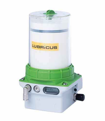
103. Description of function
3.1 General information
LUB-V is designed as an extremely compact double piston pump. The two pistons run
force-controlled and counter-rotating. LUB-V is available with one or two lubricant outlets.
The outlets are secured by an integrated non-return valve. Approx. 0.16 cm³ of lubricant
is pumped during each dispensing operation; multiple dispenses can be set one after
the other.
The LCD on the front panel displays the various operating states; further information
(empty cartridge, error) can be read.
The present Lubricus V as 24 VDC version has an electrical interface. The supplied
activation and programming key can be used to adjust the operating mode and the
quantity of lubricant pumped per time to supply the lubrication point with the ideal quantity
of lubricant.
3
0 10
5 6
1
4 8
9
2 7
Fig. 1: Overview LUB-V
No. Description
0 Lubricus V (LUB-V)
1 LCD
2 Action area (for actions with the activation and programming key)
3 Activation and programming key
4 Lubricant outlet(s) (different versions available)
5 Retaining ring
6 Housing (different versions available)
7 M12x1 electrical interface
8 Nameplate with designation, CE mark and serial number
9 Clearance hole for assembly
10 Lubricant inlet with thread for cartridge
113.2 Nameplate and designation
The nameplate of LUB-V is visibly attached to the side of the pump itself. There the
CE mark and the serial number of LUB-V are visible. Refer to chapter 3, Fig. 1 for the
location of the nameplate and serial number.
3.3 Scope of delivery
LUB-V is available in several different versions. They differ in type (for 250 or 400 ml
cartridge), number of outlets and accessories supplied.
123.4 Technical data
Housing
Dimensions without cartridge 107 x 56.5 x 108
Dimensions with housing 250 ml WxHxD 107 x 165 x 108 mm
Dimensions with housing 400 ml 107 x 198.5 x 108
Weight (incl. empty cartridge, depending on 1061 - 1124 g
model)
Mounting options holes for screw M6
Mounting position upright
Material housing zinc die-cast / PA 6.6 GF30 / POM
Material outlet nickel-plated brass
Operating temperature -15 ... +60* °C
Lubricant and hydraulic
Cartridge volume 250 / 400 cm³
Lubricant characteristics oils and greases up to NLGI 2
Number of outlets 1/2
Hydraulic connection via PA tube
Number of lubrication points* without accessories: up to 2
with splitters: up to 8
with progressive distributors: up to 20
Max. Pressure 70 (-10%/+15%) bar
Steady state pressure 50 bar
Grease delivery per stroke 0.16 (-5%) cm³
Electrics
Display LCD
Operating voltage 24 (+/- 5%) V
Protection 0.75 (slow blow) A
Protection class IP 54
Current draw Imax < 0.3 Irest < 0.025 A
Please see chapters 7 and 8 for more information about electrics.
*The stated value is down to the individual application and may extensively differ in some cases (depending on the lubricant and further conditions).
134. Transport and storage
4.1 Packaging
LUB-V is delivered in an outer packaging (cardboard box) and - depending on the scope
of delivery - with a lubricant cartridge and other accessories in the same package. To
protect them from moisture and dirt they are also packed in PE films.
Dispose the packaging materials at designated disposal points in compliance with the
relevant national and company regulations.
After receiving LUB-V check the delivery note for completeness and correctness. Any
missing parts or damages must be reported immediately to the forwarding agent, the
insurance company or Gruetzner GmbH in writing.
4.2 Transport
NOTICE
Hard shocks due to e.g. falling or setting down too hard can
damage LUB-V.
• Do not throw LUB-V.
• When using lifting equipment only use hoists and load hand-
ling attachments in perfect condition and with sufficient load
capacity.
• The permissible lifting weight of the lifting device must not be
exceeded.
4.3 Storage
Store LUB-V in its original packaging in a vertical position in a dry, frost-free environment
at an ambient temperature of +5 °C to +30 °C. The maximum storage time in unopened
condition is 2 years.
The so-called "first-in-first-out" principle (fifo) is recommended for storage logistics.
145. Mounting
5.1 Preparations
Before starting to work, inform yourself in detail about LUB-V using this user manual; and
follow the general safety instructions (section 2.7) in particular. Prepare the installation
site carefully.
NOTICE
Pressurised air can damage the seals of LUB-V and can trans-
port dirt and foreign matter into LUB-V or the lubricant.
• Do not use pressurised air.
• Make sure that there is no coarse dirt in the mounting area.
5.2 Assembly
1 Condition as delivered
LUB-V is delivered in a cardboard box.
Depending on the version ordered further
accessories such as battery, lubricant
cartridge or brackets are included. It also
contains a short manual for experienced
users to start up and assemble the unit for
the first time.
2 Remove housing from power unit
lSeparate the housing from the power unit
by turning the retaining ring counterclockwise.
Make sure that no dirt, water or foreign
bodies enter the lubricant inlet.
153 Remove cartridge cap
lTurn the cap of the lubricant cartridge
counterclockwise and pull it off.
Pay attention to cleanliness when
carrying out the work. Be sure to prevent dirt,
liquids and foreign bodies from entering the
cartridge.
164 Mount lubricant cartridge
lPlace the full lubricant cartridge on LUB-V
(label facing front).
lTurn the lubricant cartridge clockwise
onto LUB-V.
The end position is reached after two full
rotations when the label of the lubricant car-
tridge is aligned with the front of LUB-V.
5 Assemble housing on power unit
lPlace the dismantled housing on LUB-V
and press it onto the power unit.
lFasten the housing to the power unit by
turning the retaining ring clockwise.
The retaining ring must snap into place
when turning and be completely tightened.
176 Remove protective cap on the side of
LUB-V
lRemove the black protective cap from the
electrical interface on the side of LUB-V.
7 Connect electrical interface
lTo connect LUB-V with an external power
supply system add a proper connecting
cable to the electrical interface on the side
of LUB-V.
Depending on the application connecting
cables with both straight or angled sockets
can be used.
For more details on connecting cables
please see chapter 8.1.
DANGER
Damaged or flawed electrical connections or unlicensed hot
components lead to heavy injuries or even death.
• All work on electrical connections shall be provided by quali-
fied personnel only.
• Immediately change damaged cables or plugs.
• Before working on electrical installations, always follow the five
safety regulations of electrical engineering:
- Isolate
- Protect against accidental restart
- Ensure all parts are deenergized
- Ground and short-out
- Cover nearby hot components
185.3 Commissioning
Mount LUB-V carefully according to the steps described in chapter 5.2. Depending on the
scope of delivery you must also carry out the following additional measures for first-time
commissioning:
1. Mechanical fastening
Fix LUB-V mechanically. Pay particular attention to the maximum tightening torques.
2. Electrical connection
Connect LUB-V with an external power supply system (e.g. PLC) by adding a proper
connecting cable to the electrical interface on the side of LUB-V.
3. Check the assembly
Make sure that LUB-V is assembled properly and completely. In particular, the external
power supply system has to be connected and a lubricant cartridge must have been
fitted.
4. Power on
If you want to put LUB-V into operation, switch on LUB-V. LUB-V only delivers lubricant to
the lubrication point according to the settings when switched on. The detailed description
for powering on can be found in chapter 6.3.3.
5. Execute FIL function
Execute the FIL function. The detailed description can be found in chapter 6.3.9. LUB-V
performs a certain number of strokes and transports lubricant from the cartridge to the
outlet.
6. Hydraulic connection
Connect the consumer hydraulically to LUB-V. If you connect tubes to LUB-V make sure
that tubes and connectors are installed tightly, cleanly and correctly.
Ideally, use tubes prefilled with the appropriate lubricant.
7. Check the settings on LUB-V
Check the required values for the lubrication point at the factory settings of LUB-V and
adjust them if necessary. changes at LUB-V can be made in the SET menu, chapter.
6.3.7, and in the PRO menu, chapter 6.3.9 to 6.3.11.
196. Operation and settings
6.1 General information
What you should know about operating and setting LUB-V:
LUB-V is suitable as a multi-point lubricator for one or two lubrication points. However,
depending on the specific application, LUB-V can also reliably and cleanly supply a limited
number of lubrication points with lubricant. Accessories from the manufacturer (e. g.
splitters or progressive distributors) can be connected to LUB-V. If necessary, changes
must be made to LUB-V settings to ensure safe and reliable operation.
LUB-V is a cycle controlled lubricator which works time-based via the integrated micro-
electronics and is connected to a 24 VDC power supply. LUB-V cyclically delivers a
defined quantity of lubricant from the cartridge to the outlet. Three operation modes can
be selected.
Hour mode -h- allows setting the number of cycles (c) and a pause time (h) between
two dispensing cycles in hours. Pause times (h) between 1...240 hour(s) and cycles (c)
between 1...30 can be set.
The empty time mode Et allows the emptying time of the cartridge to be set in months.
Emptying times between 1...36 month(s) can be set.
Additionally, LUB-V can be embedded into a programmable logic controller (PLC) which
sends orders and controls LUB-V in impulse mode (see chapters 6 and 8). How to
switch to operation mode PUL is described in detail in chap. 6.3.8.
A dispensing cycle consists of at least one (1) dispense (stroke) and can consist of a
maximum 30 dispenses. Up to 30 dispenses per outlet are made in direct succession.
After the end of the lubrication cycle LUB-V rests until the set pause time h has elapsed
and then automatically carries out the next lubrication cycle.
The disposable interchangeable cartridge with 250 or 400 ml lubricant guarantees a
controlled and constant quality of the lubricant and is filled bubble-free. LUB-V allows a
high supply security of the lubrication point and prevents failures.
LUB-V cannot be used without a lubricant cartridge. Depending on the version ordered
the cartridge can already be included in the scope of delivery and may already be
connected and installed in LUB-V.
The respective conditions of LUB-V can be seen in the LCD. It additionally enables the
optical recognition of the condition by means of coloured LEDs.
If you have any questions about your application and the correct settings for LUB-V
please contact the manufacturer (chapter I.II).
206.2 Factory settings
LUB-V is always delivered with the following factory settings:
operating mode: hour mode -h-
mode: OFF LUB-V is switched off
The factory settings provide the use of LUB-V in hour mode -h-. If you would like to
operate LUB-V in empty time mode Et or impulse mode PUL you have to make changes
in the SET menu of LUB-V.
6.2.1 Default settings, operating mode: hour mode -h-
Pause time h = 3 The pause time is 3 hours.
Number of cycles c = 1 The number of cycles is one (1) stroke
per outlet.
The default settings in hour mode when using a LUB-V with one (1) lubricant outlet
result in an emptying time (service life) of 313 days (= 10 months) for a full 400 ml
lubricant cartridge and accordingly 196 days (= 6.5 months) for a full 250 ml lubricant
cartridge, provided that LUB-V is permanently switched on and no special dispenses
have been made. Within approx. 3 hours, LUB-V will deliver one dispense per stroke
(0.16 cm³).
If you are using LUB-V with one (1) lubricant outlet, one dispensing stroke will be
delivered from one outlet at the end of the pause time. If you are using LUB-V with two
(2) lubricant outlets, one stroke per outlet will be delivered at the end of the pause time.
The emptying time of the cartridge is halved.
lVerify that the default settings are appropriate for your application and that
the lubrication point is supplied with the correct amount of lubricant per time unit.
If this is the case, you can operate LUB-V with the default settings in hour mode -h-.
If this is not the case change the values for the pause time h and number of cycles c
accordingly; see chapter 6.3.7 for an explanation of how to make these changes.
To use LUB-V it must be properly mounted and installed first and then switched on.
The installation is very simple and is described in detail in chapter 5.2; switching on is
described in chapter 6.3.3.
If you order a factory-provided special version of LUB-V, the information contained in
the supplement is authoritative.
216.2.2 Default settings, operating mode: empty time mode Et
Emptying time Et = 6 The emptying time of one (1) cartridge is 6 months.
The default settings in empty time mode result in an emptying time (service life) of
6 months for a full 250/400 ml lubricant cartridge, provided that LUB-V is permanently
switched on and no special dispenses have been made.
lVerify that the default settings are appropriate for your application and that
the lubrication point is supplied with the correct amount of lubricant per time unit.
If this is the case, you can operate LUB-V with the default settings in empty time mode Et.
If this is not the case change the values for the emptying time t or cartridge size accor-
dingly.
To use LUB-V, it must first be properly mounted and installed and then switched on.
The installation is very simple and is described in detail in chapter 5.2; switching on is
described in chapter 6.3.3.
If you order a factory-provided special version of LUB-V, the information contained in
the supplement is authoritative.
6.2.3 Default settings, operating mode: impulse mode PUL
Impulse mode PUL enables embedding LUB-V in an external control (PLC) to command
and control the device. The number of strokes (one stroke=0,16 cm³) dispensed now
depend on the PLC’s signals.
lEnsure that your PLC program is appropriate for your application and that the lubri-
cation point is supplied with the correct amount of lubricant per time unit.
If this is the case, you can operate LUB-V in impulse mode PUL.
If this is not the case, change settings of your PLC.
To use LUB-V it must first be properly mounted and installed and then switched on.
The installation is very simple and is described in detail in chapter 5.2; switching on is
described in chapter 6.3.3.
If you order a factory-provided special version of LUB-V the information contained in
the supplement is authoritative.
226.3 Menu and LCD messages
The LCD of LUB-V can be used to read information, to change settings with the activation
and programming key on the top of LUB-V or to trigger individual actions.
Generally, settings can be changed and actions can be triggered when LUB-V is switched
off (OFF) and when it is switched on (ON).
The individual submenus are presented, described and explained in detail in chapters
6.3.4 to 6.3.12.
The symbolic representations used below are described as follows:
Symbol Description Note Chapter
LCD display The LCD displays 6.3.1
information both during
On operation and for
programming purposes.
Sequence The black sequence ./.
arrow arrow indicates the
unchangeable basic
structure of the menu.
Action arrow The blue action arrow 6.3.2
shows the consequence
of touching the action
area with the activation
and programming key.
Submenu In the respective 6.3.4 to
submenu's information 6.3.12
Unter-Menü
SUB-Menü can be read, dispensing
processes can be
initiated and settings
can be changed.
23The graphic above illustrates the unchangeable basic flowchart of the LUB-V menu
navigation as well as the options for branching to submenus.
LUB-V can be switched on and off at several points in the menu navigation. For details
see chapter 6.3.3.
The INF menu can only be accessed from OFF mode (LUB-V is switched off).
The INF menu provides you with an informative overview of the current LUB-V settings.
For details see chapter 6.3.4 and 6.3.5.
The SET menu can only be accessed from OFF mode (LUB-V is switched off).
The SET menu allows you to make changes to the operating mode. Details can be found
in chapter 6.3.6.
The RUN menu can only be accessed from ON mode (LUB-V is switched on).
The RUN menu allows you to manually trigger a single dispense at LUB-V. For details
see chapter 6.3.7.
24 The PRO menu is only accessible from ON mode (LUB-V is switched on).
The PRO menu allows you to make changes to the LUB-V settings - and thus to its
dispensing behavior. For details see chapter 6.3.8 and 6.3.9.
The FIL menu is only accessible from ON mode (LUB-V is switched on).
The FIL menu allows you to manually trigger a fixed number of dispenses at LUB-V. For
details see chapter 6.3.10.
256.3.1 LCD
The LCD diplays information about various states of LUB-V.
Depending on the state of the LUB-V you will be supported by three coloured LEDs to the
right of the LCD. This allows you to assess the condition of LUB-V from a distance. Basic
meanings: green=OK; red=error. The following tables show the LED assignment on the
LCD as well as the explanation of the respective output.
LCD Assignment
upper LED: red
On middle LED:
lower LED:
yellow
green
LCD Description Naming Chapter
The red LED only lights up if there Error on 6.4
On is an error. LUB-V
The yellow LED only lights up if the Activation and 6.3
On activation and programming key has
touched the action surface (activation
and programming key detected).
programming
key detected
by LUB-V
The green LED lights up during LUB-V 6.3
On a dispensing process for approx. dispenses
7...17 seconds. lubricant
The green LED lights up when Changes 6.3
On changes are possible and the possible
activation and programming key
was previously detected.
The green LED flashes every 5 LUB-V is 6.3
On seconds when LUB-V is ON and ready for
no error occurs. use
The green LED flashes twice Acceptance 6.3
On when a value has been
confirmed. Additionally the LCD
also flashes twice.
of changed
value
26Display in LCD Meaning Chapter
no display Power supply not connected 5.3
OFF LUB-V is switched off 6.3.3
On LUB-V is ready for operation; LUB-V dispenses lubricant 6.3.3
in accordance to the operating mode and the values set
PUL LUB-V is ready for operation in impulse mode PUL and 8
waits for control signals from the PLC
PUL (flashing) LUB-V is receiving a control signal from the PLC 8
--- Received control signal longer than 15 seconds 8.2
Errors
E1 Error E1 (empty cartridge) 6.4
E2 Error E2 (overload / overpressure) 6.4
E3 Error E3 (undervoltage) 6.4
E4 Error E4 (fatal error) 6.4
Submenus
INF INF menu 6.3.4
b01 Firmware version of LUB-V 6.3.5
h03 Currently set value of pause time h
c01 Currently set value of number of strokes c
6 Currently set value of emptying time Et
PUL Currently set operating mode: impulse mode
SET SET menu 6.3.7
-h- Operating mode: hour mode
Et Operating mode: empty time mode
PUL Operating mode: impulse mode
RUN RUN menu 6.3.6
01...70 During the manually triggered active RUN command
("Quick check"/extra dispense), the LCD displays the
approximate back pressure in bar. In addition, the green
LED lights up.
27PRO PRO menu 6.3.7
h1...99 Adjustable setting of pause time h
c1...30 Adjustbale setting of number of strokes c
1...36 Adjustabe setting of emptying time Et
PUL Currently set operating mode: impulse mode
No changeable value
FIL FIL menu 6.3.9
01...70 During the manually triggered, active FIL command, the
LCD displays the approximate back pressure in bar. In
addition, the green LED lights up.
Clr If the process is aborted during the FIL command Clr
appears at first.
Additional characters on the LCD
1/2 During a dispensing process LUB-V indicates from which
outlet lubricant is being pumped.
MAX After each cycle the maximum back pressure is
displayed in bar.
286.3.2 Actions with the activation and programming key
The activation and programming key attached to the top of LUB-V allows you to perform
actions and changes in the settings of LUB-V. This activation and programming key can
be easily and permanently stored on top of LUB-V.
1 Remove the key
lTurn the activation and programming key
to the OPEN position and remove it from the
housing of LUB-V.
The activation and programming key
is stored in the opening on the top of the
housing of LUB-V. It is also used to seal
LUB-V.
2 Guide the activation and programming
key to the action area
lPlace the activation and programming
key on the action area on the front of LUB-V.
As soon as the activation and programming
key on the action area has been detected by
LUB-V, the yellow LED lights up. The menu
flashes in a rhythm of approx. 2 seconds.
lRemove the activation and programming
key from the action area as long as the
desired menu item is displayed in the LCD.
The yellow LED disappears. You have
performed an action. The LCD and the green
LED flash twice.
29lAt the end of the action or setting reinsert the activation and programming key into the
hole provided on the housing of LUB-V. Then turn the activation and programming key to
the CLOSE position to restore the sealing effect.
Please note, however, that in the event of faults or changes to be made no changes or
actions can be carried out on LUB-V without the activation and programming key. If you
reattach the activation and programming key to the housing of LUB-V after carrying out
actions on LUB-V it is ensured that no dirt can get into the housing. The activation and
programming key must be reinserted in the housing of LUB-V after actions have been
performed.
306.3.3 Switching on and off
Switching on LUB-V:
LUB-V is switched off (OFF).
lHold the activation and programming key onto the action surface. The yellow LED
lights up. Leave the key on the action area until ON is displayed in the LCD. Remove the
activation and programming key from the action area as long as ON is displayed. The
yellow LED disappears; the LCD and the green LED flash twice.
If no error is detected during the LUB-V self-check, ON is displayed in the LCD.
The green LED lights up once every 5 seconds, LUB-V is ready for operation and will
dispense lubricant according to the set values.
lInsert the activation and programming key into the hole provided on top of LUB-V.
Switching off LUB-V:
LUB-V is switched on (ON), the green LED flashes every 5 seconds.
lHold the activation and programming key onto the action surface. The yellow LED
lights up. Leave the activation and programming key on the action area until OFF is
displayed in the LCD. Remove the activation and programming key from the action area
as long as OFF is displayed. The yellow LED disappears; the LCD and the green LED
flash twice.
LUB-V is OFF; OFF appears in the LCD. LUB-V stops dispensing lubricant.
lInsert the activation and programming key into the hole provided on top of LUB-V.
LUB-V can be switched off in any state (normal operating state or error) in the manner
described above.
316.3.4 INF menu: operating mode = hour mode -h-
The INF menu informs the user about the firmware used in LUB-V and the settings made
earlier and are currently active (values of the adjustable variables t and c that can be
changed in the PRO menu).
In INF menu nothing can be changed by the user. The values of the parameters are
displayed in a fixed order.
n alphanumerical name of the LUB-V firmware
h set value of variable h pause time
c set value of variable c number of cycles
lRemove the activation and programming key from the top of LUB-V and place it onto
the action area.
lHold the activation and programming key onto the action surface. The yellow LED
lights up. Leave the activation and programming key on the action area until INF is
displayed in the LCD. Remove the activation and programming key from the action area
as long as INF is displayed. The yellow LED disappears; the LCD and the green LED
flash twice.
The LCD informs you on the set values.
lInsert the activation and programming key into the hole provided on top of LUB-V.
The INF menu can only be accessed from OFF mode (LUB-V is switched off). When
you have entered the INF menu, you will return to OFF mode.
326.3.5 INF menu, operating mode: empty time mode Et
The INF menu is used to inform the user about the firmware used in LUB-V and the
settings made earlier and are currently active (value of the adjustable variable Et that can
be changed in the PRO menu).
In the INF menu nothing can be changed by the user. The values of the parameters are
displayed in a fixed order.
400
n alphanumerical name of the LUB-V firmware
Et set value of the variable Et emptying time in months
400 set value of the size of the lubricant cartridge
lRemove the activation and programming key from the top of LUB-V and place it onto
the action area.
lHold the activation and programming key on the action surface. The yellow LED lights
up. Leave the activation and programming key on the action area until INF is displayed
in the LCD. Remove the activation and programming key from the action area as long as
INF is displayed. The yellow LED disappears; the LCD and the green LED flash twice.
The LCD informs you on the set values.
lInsert the activation and programming key into the hole provided on top of LUB-V.
The INF menu can only be accessed from OFF mode (LUB-V is switched off). When
you have entered the INF menu, you will return to OFF mode.
336.3.6 INF menu: operating mode = pulse control mode PUL
The INF menu is used to inform the user about the firmware used in LUB-V and the
settings which have been made earlier and are currently active.
In INF menu nothing can be changed by the user. The values of the parameters are
displayed in a fixed order.
n alphanumerical name of the LUB-V firmware
PUL set operating mode: impulse mode (PUL)
c value of the number of cycles c (irrelevant in pulse control mode)
lRemove the activation and programming key from the top of LUB-V and place it onto
the action area.
lHold the activation and programming key on the action surface. The yellow LED lights
up. Leave the activation and programming key on the action area until INF is displayed
in the LCD. Remove the activation and programming key from the action area as long as
INF is displayed. The yellow LED disappears; the LCD and the green LED flash twice.
The LCD informs you on the set values.
lInsert the activation and programming key into the hole provided on top of LUB-V.
The INF menu can only be accessed from OFF mode (LUB-V is switched off). When
you have entered the INF menu, you will return to OFF mode.
346.3.7 SET-Menu
The SET menu allows you to change the operating mode and cartridge size of LUB-V.
You can switch between hour mode -h-, empty time mode Et and impulse mode PUL.
The hour mode -h- allows you to set the number of cycles (c) within a dispensing time (h)
in hours. The empty time mode Et allows you to set the emptying time (Et) of the cartridge
in months. The impulse mode allows you use a PLC to control LUB-V when embedded.
Cycles (c) and dispensing time (h) or emptying time (Et) can be adjusted after selecting
the operating mode in the PRO menu, see chapters 6.3.9 to 6.3.11.
-h- operating mode: hour mode -h-
Et operating mode: empty time mode Et
PUL operating mode: impulse mode PUL
250/400 cartridge size
LUB-V is switched off (OFF)
lRemove the activation and programming key from the top of LUB-V and place it onto
the action area.
lHold the activation and programming key onto the action surface. The yellow LED
35lights up. Leave the activation and programming key on the action area until SET is
displayed in the LCD.
lRemove the activation and programming key from the action area.
The yellow LED disappears; the LCD and the green LED flash twice. The LCD displays
the operating mode currently set. Now you are able to change the operating mode and
the cartridge size.
Changing the operating mode:
lIf you would like to change the operating mode, move the activation and programming
key back to the action area.
The yellow LED lights up and the LCD displays the currently unselected operating
mode. The yellow LED lights up as long as the activation and programming key is on the
action surface; the two adjustable operating modes run alternately.
lWhen your desired operating mode is displayed on the LCD, remove the activation
and programming key from the action area.
The yellow LED disappears; the LCD and the green LED flash twice. The selected
operating mode has now been accepted.
Not changing the operating mode:
lIf you do not want to change operating mode, the activation and programming key
must remain removed from the action area.
The LCD and the green LED flash twice whereby the operating mode is displayed in
the LCD.
Changing the cartridge size:
lIf you would like to change the cartridge size, move the activation and programming
key back to the action area.
The yellow LED lights up and the LCD displays the currently unselected cartridge size.
The yellow LED lights up as long as the activation and programming key is on the action
surface; the two adjustable cartridge sizes run alternately.
lWhen your desired cartridge size is displayed on the LCD, remove the activation and
programming key from the action area.
The yellow LED disappears; the LCD and the green LED flash twice. The selected
cartridge size has now been accepted.
The SET menu can only be accessed from OFF mode (LUB-V is switched off). When
you have entered the SET menu, you will return to OFF mode.
366.3.8 RUN menu
The RUN menu is used to manually activate LUB-V and enables triggering an extra
dispense. This function can be used, for example, to manually check the condition of the
lubrication point ("quick check").
LUB-V carries out a special dispense after triggering the RUN function. After triggering
the RUN function, LUB-V executes exactly as many strokes per outlet as were set in
the variable number of cycles c in the PRO menu. During the stroke, the back pressure
detected by the integrated microelectronics is displayed in the LCD as an approximate
value in bar.
There is no fault or error at LUB-V.
lRemove the activation and programming key from the top of LUB-V and place it onto
the action area.
lHold the activation and programming key onto the action surface. The yellow LED
lights up. Leave the activation and programming key on the action area until RUN is
displayed in the LCD. Remove the activation and programming key from the action area
as long as RUN is displayed. The yellow LED disappears.
The LCD and the green LED flash twice. LUB-V starts to pump the lubricant to the
outlet (extra dispense or "Quick check") depending on the value c set in PRO menu. (E.g.
if c=1 is set, the RUN function triggers one stroke. If c=4 is set, 4 strokes are dispensed.)
lInsert the activation and programming key into the hole provided on top of LUB-V or
repeat the extra dispense ("Quick check") if necessary.
lObserve the back pressure values displayed on the LCD if they are of interest.
During the dispensing process, the green LED lights up; in addition, the counterpres-
sure for the stroke is displayed in the LCD.
In empty-time mode -Et- LUB-V dispenses one stroke.
The RUN menu can only be reached from the ON mode (LUB-V switched on). When
you have entered the RUN menu, you will return to the ON mode.
376.3.9 PRO menu: operating mode = hour mode -h-
The PRO menu allows you to change the settings of LUB-V's dispensing behavior as
well as the operation mode. You can change the pause time h and the number of cycles
c (number of strokes).
After pause time h has expired LUB-V executes exactly the number of strokes c (each
0.16 cm³) specified in the number of cycles c.
There is no fault or error at LUB-V.
Being in PRO menu the first step is to set the pause time h and afterwards the number
of cycles c; direct access to the number of cycles c is not possible.
lRemove the activation and programming key from the top of LUB-V and place
it onto the action area. Hold the activation and programming key onto the action surface.
Leave the activation and programming key on the action area until PRO is displayed in
the LCD.
lRemove the activation and programming key from the action area as long as PRO is
displayed.
The LCD and the green LED flash twice. The LCD first displays the value of pause
time h (his) currently set. Now you are able to change the values of pause time h.
38Changing the value of pause time h:
lIf you would like to change the value of pause time h move the activation and
programming key back to the action area.
In the LCD the next higher (his + 1) adjustable value of pause time h is displayed.
The green LED lights up as long as the activation and programming key is placed on
the action surface; the other values of pause time h run through one after the other.
However, you can also remove the activation and programming key from the action area
and bring it back there shortly afterwards to reach each value one after the other. If the
final value of the pause time h of h=240 is reached and no value has been selected the
menu returns to h=01 and the cycle can be restarted.
lAs long as the new chosen value you choose for pause time h (hnew) is displayed in the
LCD remove the activation and programming key from the action area.
The yellow LED disappears, the green LED and the LCD flash twice. The selected
new value (hnew = his) of pause time h has now been accepted. The submenu will now
automatically take you to the values of the number of cycles c.
No changing of the value of pause time h:
lIf you do not want to change the value of pause time h the activation and programming
key must remain removed from the action area immediately after entering the PRO menu.
The LCD as well as the green LED flash twice and the pause time h is displayed in the
LCD. The submenu now automatically takes you to the values of the number of cycles.
The LCD now displays the currently set value of the number of cycles c (cis). Now you
have the possibility to change the values of the number of cycles c.
Changing the value of the number of cycles c:
lIf you want to change the value of the number of cycles c move the activation and
programming key back to the action area.
In the LCD the next higher (cis + 1) adjustable value of the number of cycles c is
displayed. The green LED lights up as long as the activation and programming key is
placed on the action surface; the other values of the number of cycles c run through one
after the other. However, you can also remove the activation and programming key from
the action area and bring it back there shortly afterwards to reach each value one after
the other. If the final value of the number of cycles c of c=30 is reached and no value has
been selected, the menu returns to c=01 and the cycle can be restarted.
lAs long as the new chosen value for the number of cycles c (cnew) is displayed in the
LCD remove the activation and programming key from the action area.
The yellow LED disappears, the green LED and the LCD flash twice. The selected new
value (cnew = cis) of pause time h has now been accepted.
39No changing of the value of the number of cycles c:
lIf you do not want to change the value of the number of cycles c the activation and
programming key must remain removed from the action area immediately after entering
the PRO menu.
The LCD and the green LED flash twice and the number of cycles c is displayed in
the LCD.
lInsert the activation and programming key into the hole provided on top of LUB-V.
The PRO menu can only be reached from ON mode (LUB-V switched on). When
leaving the PRO menu you will return to ON mode.
If you have made changes to the values of pause time h or number of cycles c in
PRO menu and LUB-V is otherwise ready for operation (battery full and inserted as well
as a cartridge fitted), LUB-V will immediately trigger the newly set dispense and start the
newly set waiting time until the next dispenses.
lInsert the activation and programming key into the hole provided on top of LUB-V.
lObserve the back pressure values displayed on the LCD if they are of interest.
During the dispensing process the green LED lights up; in addition, the stroke's
counterpressure is displayed in the LCD.
The parameters that can be set for pause time h and the number of cycles c and their
respective permissible values are specified as follows:
h= Pause time in hours (h).
The pause time can be set between 1 | 2 | 3 | ... | 240 hours.
The time counter integrated in the microelectronics of LUB-V starts
counting the pause time h at the end of a successful and fully completed
dispensing cycle.
c= Number of cycles within a dispensing cycle (c).
The number of cycles c can be set between 1 | 2 | 3 | ... | 30 strokes.
406.3.10 PRO menu, operating mode: empty time mode Et
The PRO menu allows you to change the settings of the LUB-V's dispensing behavior.
Running empty time mode Et, you can change the emptying time Et in months. LUB-V
automatically calculates the pause time between two cycles to reach the set emptying
time in months.
36
There is no fault or error at LUB-V.
lRemove the activation and programming key from the top of LUB-V and place
it onto the action area. Hold the activation and programming key onto the action surface.
Leave the activation and programming key on the action area until PRO is displayed in
the LCD.
lRemove the activation and programming key from the action area as long as PRO is
displayed.
The LCD and the green LED flash twice. The LCD first displays the value of the
emptying time Et (Etis) currently set. You are now able to change the values of emptying
time Et.
Changing the value of emptying time Et:
lIf you would like to change the value of emptying time Et, move the activation and
programming key back to the action area.
41 In the LCD the next higher (Etis + 1) adjustable value of emptying time Et is displayed.
The green LED lights up as long as the activation and programming key is placed onto
the action surface; the other values of emptying time Et run through one after the other.
However, you can also remove the activation and programming key from the action area
and bring it back there shortly afterwards to reach each value one after the other. If the
final value of emptying time Et of Et=36 is reached and no value has been selected the
menu returns to Et=01 and the cycle can be restarted.
lAs long as the new chosen value for emptying time Et (Etnew) is displayed in the LCD
remove the activation and programming key from the action area.
The yellow LED disappears, the green LED and the LCD flash twice. The selected new
value (Etnew = Etis) of pause time h has now been accepted.
No changing of the value of emptying time Et:
lIf you do not want to change the value of emptying time Et the activation and
programming key must remain removed from the action area immediately after entering
the PRO menu.
The LCD an the green LED flash twice and emptying time Et is displayed in the LCD.
lInsert the activation and programming key into the hole provided on top of the housing
of LUB-V.
The PRO menu can only be reached from ON mode (LUB-V switched on). When
entering the PRO menu, you will return to ON mode.
If you have made changes to the values of emptying time Et in PRO menu and LUB-V
is otherwise ready for operation (battery full and inserted as well as a cartridge fitted),
LUB-V will immediately start the calculated waiting time until the next dispenses.
lObserve the back pressure values displayed on the LCD if they are of interest.
During the dispensing process the green LED lights up; in addition, the stroke's
counterpressure is displayed in the LCD.
The parameters that can be set for emptying time Et and their respective permissible
values are specified as follows:
Et= Emptying time of a full cartridge in months (Et).
The emptying time can be set between 1 | 2 | 3 | ... | 36 months.
The time counter integrated in the microelectronics of LUB-V starts counting
the pause time at the end of a successful and fully completed dispensing cycle.
426.3.11 PRO menu, operating mode: impulse mode PUL
The PRO menu allows you to change the settings of the LUB-V's dispensing behavior.
Running impulse mode PUL, settings can not be changed. An external control (PLC) in
which LUB-V is embedded commands and controls the device, see chapters 6 and 8.
The display shows PUL (impulse mode) for your information.
436.3.12 FIL menu
The FIL menu allows you to trigger a defined multiple dispense of LUB-V. The activation
initiates a total of 40 pump strokes. This function enables you to prefill connected acces-
sories (tubes, distributors,...) with the lubricant contained in the lubricant cartridge,
especially during the initial start-up of LUB-V. However, the process can also be aborted
manually at any time.
There is no fault or error at LUB-V.
lRemove the activation and programming key from the top of LUB-V and place it on
the action area. The yellow LED will light up. Leave the activation and programming
key on the action area until FIL is displayed in the LCD. Remove the activation and
programming key from the action area. The yellow LED disappears.
The LCD and the green LED flash twice. LUB-V starts dispensing. The green LED
lights up during each dispense.
lIf you do not want to cancel the process: Insert the activation and programming key
into the hole provided on top of LUB-V.
LUB-V dispenses 40 strokes of lubricant.
lIf you would like to cancel the process: Place the activation and programming key on
the action area and wait until the end of a dispensing process (motor run).
CLR appears in the LCD.
lRemove the activation and programming key from the action area.
LUB-V stops the FIL command.
lObserve the back pressure values displayed on the LCD if they are of interest.
44 During the dispensing process the green LED lights up; in addition, the stroke's
counterpressure is displayed in the LCD.
The FIL menu can only be reached from ON mode (LUB-V switched on). When you
enter the FIL menu you will return to ON mode, even if you cancel FIL prematurely with
CLR.
6.4 Error codes
The microelectronics integrated in LUB-V permanently monitor the status. In case of
irregularities an addressed error message is displayed on the LCD. The red LED flashes
every 5 seconds and signals an error.
LCD Name Description Remedy
Error Cartridge lPlace a new cartridge on
E1 E1 empty LUB-V (see chapter 9.2).
No confirmation of error
necessary; it is automatically
cleared after the remedial
action.
Error Overload, the lCheck the lubrication point
E2 E2 backpressure
at the lubri-
cation point is
too high
and eliminate the fault's cause.
lSwitch LUB-V off (OFF) and
on (ON) again.
Error Undervoltage lSwitch LUB-V off (OFF).
E3 E3
Error Fatal error
lCheck the power supply of
LUB-V.
lSwitch LUB-V on (ON).
lDisassemble LUB-V and
E4 E4 return it to the manufacturer
together with the lubricant
cartridge and a description of
faults.
A fatal error usually
concerns the electronics of
LUB-V and cannot be repaired
by you on site.
The manufacturer's
address can be found in
chapter I.II.
457. Input and output signals - time control
LUB-V operates in hour mode -h- or empy time mode Et as a time-based and cycle-con-
trolled lubrication system according to the values set in PRO menu.
7.1 Pin assignment - time control
PIN assignment
3 2 PIN Assignment Colour
1 +24 V DC brown
2 unallocated white
3 ground blue
4 1 4 output signal black
Type: M12x1 female connector; 4-pin, A-coded
LUB-V can be switched off completely by switching off the supply voltage.
After reapplying the supply voltage LUB-V checks itself automatically but only operates
after receiving an input signal from the PLC.
After a long standstill of LUB-V a "quick check" is recommended (chapter 6.3.6).
The output signal at PIN 4 can be tapped for further processing (e.g. indicator light or
external control). The maximum permissible current output must not exceed Imax < 20mA.
No inductive load (e.g. relay) may be connected!
7.2 Output signals and LCD messages - time control
LCD Description Output Signal (PIN 4) Chapter
OFF switched off low, permanent
On ready for operation high, permanent
E1 cartridge empty 0,5Hz square wave signal,
permanent 7.3
E2 overload low, permanent
E3 undervoltage low, permanent
E4 fatal error low, permanent
467.3 Output signals at PIN 4 - time control
LUB-V provides two output signals in hour mode -h (factory setting) via the electrical in-
terface. If required, the operating states of LUB-V can be processed externally. Basically,
the output signals can only be sampled and must not be subjected to inductive loads or
low ohmic loads. Besides LCD and LED this also allows a status control from a distance.
Output signal high level (+24 V) at PIN 4:
U
24V
PIN 4
0V t
Description:
A permanently and continuously present high level (+24 V) at PIN 4 means that LUB-V
is ready for operation and there is no error. LUB-V will operate according to the settings
made and will accordingly convey lubricant from the cartridge to the outlet.
Output signal low level (0 V) at PIN 4:
U
24V
PIN 4
0V t
Description:
A permanent low level (0V) at PIN 4 means that LUB-V is either switched off or - if it
is switched on - an error occured. The error must be read out from the LCD of LUB-V
(chapter 6.4). LUB-V does not pump lubricant!
478. Input and output signals - external control (PLC)
To command LUB-V via an external controller (PLC) it is necessary to switch LUB-V to
pulse control mode PUL in PRO menu (chapter 6.3.8).
In pulse control mode LUB-V operates as a pulse-controlled lubrication system only if
unalterable input signals (high level) are transmitted from the PLC to LUB-V via PIN 2 in
a defined sequence. LUB-V signals the respective status to the PLC via high/low levels
which can be tapped off at PIN 4 and thus enables comprehensive control or, by suitable
programming of the PLC, differentiated evaluation of the different states. To integrate
LUB-V into an external control one input and one output must be provided on the control
side.
8.1 Pin assignment - external control (PLC)
PIN assignment (PLC)
3 2 PIN Assignment Colour
1 +24 V DC brown
2 Input Signal PLCLUB-V white
3 Ground blue
4 1 4 Output Signal LUB-VPLC black
Type: M12x1 female connector; 4-pin, A-coded
To electrically connect LUB-V to the PLC of your machine the device provides a 4-pin
interface which is designed as a standard industrial M12x1 plug connection.
LUB-V can be switched off completely in pulse control mode by switching off the
supply voltage. The settings made are not lost. After reapplying the supply voltage LUB-V
checks itself automatically but only operates after receiving an input signal from the PLC.
To operate LUB-V via an external controller (PLC) in pulse control mode a program
corresponding to the communication protocol must be created in the PLC. A basic
flowchart for commanding LUB-V can be found in the appendix (chapter 11.4).
The output signal at PIN 4 can be tapped for further processing (e.g. indicator light or
external control). The maximum permissible current output must not exceed Imax < 20mA.
No inductive load (e.g. relay) may be connected!
After a long standstill of LUB-V a manually triggered single dispense is recommen-
ded. (2 seconds signal).
48You can also read