Subaru AcccessTUNER Software
←
→
Page content transcription
If your browser does not render page correctly, please read the page content below
Subaru AcccessTUNER Software

                          USDM 2.5L Speed Density Guide

                                      Version 1.1

            Prepared by: COBB Tuning Calibration and Engineering Teams

Documents Available:

USDM 2.5L ECU Software Change Guide
USDM 2.0L ECU Software Change Guide
USDM 2.5L Speed Density Guide
USDM Subaru Monitor Descriptions
USDM Subaru Table Descriptions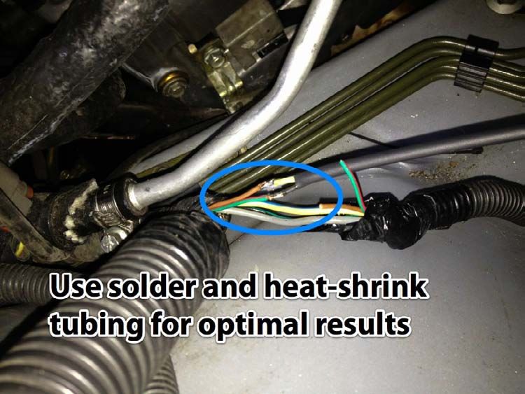
Table of Contents
Overview............................................................................................................................................................................... 5
Uses....................................................................................................................................................................................... 5
Supported Vehicles List......................................................................................................................................................... 5
Glossary of Acronyms............................................................................................................................................................ 5
Features................................................................................................................................................................................. 6
Hardware Requirements........................................................................................................................................................ 7
Warnings............................................................................................................................................................................... 8
   OFF-ROAD USE ONLY......................................................................................................................................................... 8
   READ ALL DOCUMENTATION BEFORE TUNING.................................................................................................................. 8
   SD IS NOT FOR INEXPERIENCED SUBARU TUNERS ............................................................................................................. 8
   VERIFY FACTORY AIRFLOW AND LOAD LIMITS AND RAISE AS NEEDED.............................................................................. 8
   MANIFOLD PRESSURE SENSOR CHECK ENGINE LIGHT ERRATIC LOAD CALCULATION ........................................................ 8
   ENGINE HARDWARE CHANGES MAY REQUIRE A RE-TUNE FOR SD.................................................................................... 9
   POTENTIAL RISKS FOR SD WITH A HEAT SOAKED IAT SENSOR ........................................................................................... 9
SD Installation Steps............................................................................................................................................................ 10
What is Speed Density?....................................................................................................................................................... 11
What is Volumetric Efficiency?............................................................................................................................................ 11
Volumetric Efficiency Table.................................................................................................................................................. 11
SD Modes............................................................................................................................................................................ 12
Tuning SD – Mechanical Configuration................................................................................................................................ 13
Tuning SD – Getting Started................................................................................................................................................. 13
Tuning SD – Initial Map Configuration................................................................................................................................. 13
       Airflow and Load Limits............................................................................................................................................... 13
       Manifold Pressure Sensor Diagnostic Trouble Codes ................................................................................................... 13
       Load and MAF Compensation...................................................................................................................................... 14
       Conservative Fuel and Timing Maps............................................................................................................................ 15
       Injector Scaler and Latency.......................................................................................................................................... 15
       Engine Displacement................................................................................................................................................... 15
       VE Table Axis Scaling.................................................................................................................................................... 15
       Reflash Changes........................................................................................................................................................... 16
Tuning SD – Starting Values for the VE Table....................................................................................................................... 16

                                                            Copyright © 2012 Cobb Tuning Products, LLC. All Rights Reserved
                                                                                                                                                                                  Page 2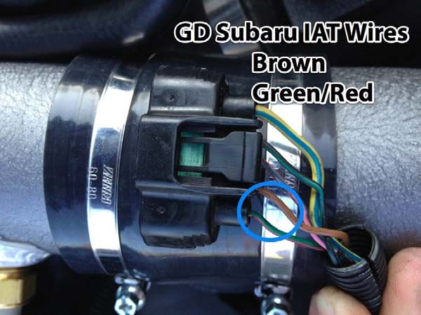
Car with Working and Accurate MAF Sensor............................................................................................................... 16
       Car without Viable MAF Sensor Configuration............................................................................................................ 17
Tuning SD – The Tables........................................................................................................................................................ 18
   “SD Volumetric Efficiency” Table..................................................................................................................................... 18
   “SD Airflow Compensation (Intake Temp)” Table............................................................................................................. 19
   “SD Airflow Compensation (Coolant Temp)” Table.......................................................................................................... 21
   “SD Airflow Compensation (Barometric)” Table.............................................................................................................. 21
Tuning SD – Miscellaneous Tables....................................................................................................................................... 21
       Load Filtering in MAF and SD Mode............................................................................................................................ 22
       Map Determination Averaging Window...................................................................................................................... 22
       SD Feature Activation.................................................................................................................................................. 23
Tuning SD – Post-Tune Recommendations.......................................................................................................................... 23
Tuning SD – Additional Topics.............................................................................................................................................. 24
       Recommended Calibrations for Aftermarket IAT Sensors............................................................................................ 24
       ..................................................................................................................................................................................... 24
       Recommended Calibrations for Aftermarket MAP Sensors ......................................................................................... 24
       Forcing Open Loop Fueling.......................................................................................................................................... 25
       Long-Term Fuel Trims................................................................................................................................................... 25
       Removing Influence of Rear Oxygen Sensor on Fueling............................................................................................... 26
       Cam Timing (AVCS) Tuning Changes and Effect on VE .................................................................................................. 27
Tuning MAF Mode............................................................................................................................................................... 27
Tuning Hybrid Mode............................................................................................................................................................ 27
       Overview..................................................................................................................................................................... 27
       Hybrid Mode - Uses..................................................................................................................................................... 28
       Hybrid Lower/Upper Mode......................................................................................................................................... 28
       Hybrid Threshold Switching Behavior.......................................................................................................................... 28
       Hybrid Thresholds Overview........................................................................................................................................ 29
       Hybrid Threshold Individual Deactivation.................................................................................................................... 29
       Hybrid Transition Blending.......................................................................................................................................... 29
Tuning Hybrid Mode – Post-Tune Recommendations .......................................................................................................... 30
How to Monitor the Tune.................................................................................................................................................... 31
SD Real-Time Tuning............................................................................................................................................................ 34
       Row/Column Table Data and Dynamic Advance Tables Removed from Real-Time ...................................................... 34

                                                            Copyright © 2012 Cobb Tuning Products, LLC. All Rights Reserved
                                                                                                                                                                                    Page 3
Other Changes to Real-Time ....................................................................................................................................... 34
       Real-Time Tunable SD Tables....................................................................................................................................... 34
SD Airflow Math.................................................................................................................................................................. 35
       Ideal Gas Law – Introduction....................................................................................................................................... 35
       Ideal Gas Law – Real-World Inputs.............................................................................................................................. 35
       Ideal Gas Law – Volumetric Efficiency.......................................................................................................................... 36
       Ideal Gas Law – Mass Airflow...................................................................................................................................... 36
       Ideal Gas Law – SD Reference Airflow.......................................................................................................................... 36
       SD Final Airflow........................................................................................................................................................... 37
       Estimated VE Calculation............................................................................................................................................. 38
Appendix – Aftermarket IAT Sensor Install.......................................................................................................................... 40

                                                         Copyright © 2012 Cobb Tuning Products, LLC. All Rights Reserved
                                                                                                                                                                           Page 4
INTRODUCTION
Overview
The COBB Speed Density feature is a powerful yet easy-to-use solution that integrates Speed Density tuning into the
Subaru engine control unit (ECU) and can be used to entirely replace or work in conjunction with the existing factory
mass airflow (MAF) sensor. It is highly customizable and features such as real-time tuning aid in a speedy and efficient
tuning process.

Uses
COBB Speed Density (SD) has a number of potential uses that can improve the tuning capability for particular set-ups:

    •   SD can eliminate the noisy airflow calculation sometimes seen when using a MAF sensor-based configuration
        with heavily modified cars.

    •   SD allows for the MAF sensor to be removed, eliminating a potential restriction in the intake tract and allowing
        for more freedom in intake piping design.

    •   In a special hybrid mode, SD can be used on the high end to overcome a maxed out MAF sensor, while still
        retaining MAF sensor operation on the low end. Or SD can be used on the low end to improve idle/cruise
        characteristics when a big MAF is used, while still retaining MAF sensor operation on the high end.

Supported Vehicles List
The following vehicles designed for and sold in North America are supported:

            •   2006-2012 Subaru Impreza WRX

            •   2004-2012 Subaru Impreza STI

            •   2009 Subaru Impreza 2.5GT

            •   2004 - 2012 Subaru Forester XT

            •   2005-2012 Subaru Legacy GT

            •   2005-2009 Subaru Outback XT

Glossary of Acronyms
            •   ECT = Engine Coolant Temperature

            •   ECU = Engine Control Unit

            •   IAT = Intake Air Temperature

                                      Copyright © 2012 Cobb Tuning Products, LLC. All Rights Reserved
                                                                                                                  Page 5
• IC = Intercooler
• MAF = Mass Airflow
• MAP = Manifold Absolute Pressure
• RPM = Revolutions Per Minute (referring to engine speed)
• SD = Speed Density
• VE = Volumetric Efficiency
• WBO2 Sensor = Wideband Oxygen Sensor
Features
The following is a list of the key features of COBB Speed Density (SD):
• SD works by calculating a new SD-based airflow to replace the factory MAF sensor-based airflow when SD is
active. This keeps much of the existing factory logic in place, allowing for the safe and reliable operation of the
factory ECU while reducing the learning curve associated with tuning SD.
• Adding the SD functionality to your existing COBB maps is a simple as opening the map in the AccessTUNER
software with the SD ECU selected, saving the map, transferring the map to the AccessPORT, and reflashing
the map to the car. From there, you simply start tuning with the AccessTUNER software.
• Tuning SD is achieved through manipulating a real-time tunable volumetric efficiency (VE) table. Because the
VE table units represent actual VE, properly calibrated SD tunes can be used to compare VE across different
cars with different mods, even if the SD airflow is drastically different.
• A real-time tunable intake air temperature (IAT) compensation table allows the tuner to tweak the SD charge
temperature correction. This table can be tweaked according to manifold pressure, allowing for changes that
may be needed based on IAT sensor placement. SD airflow compensations for engine coolant temp (ECT) and
barometric pressure are also available.
• Tuners can select from three different real-time tunable modes of operation. MAF mode mimics the factory
logic in which airflow is determined by the MAF sensor and the “MAF Calibration” table. This mode allows you
to get a starting VE table up and running before actually running SD or allows you to tune MAF sensor
calibration as you would with the factory ECU. SD mode is full-time SD operation where the ECU uses the SD-
based airflow calculation. Hybrid mode allows for switching between MAF and SD mode (and vice versa)
based on thresholds of throttle, RPM, MAP and MAF voltage. During the transition, the MAF sensor and SD-
based airflow calculations will be blended over a short period of time to allow for a smooth transition between
modes. The speed of this transition and how the switching takes place can also be configured.
• The SD and MAF sensor-based calculations are made regardless of mode. This means that the MAF sensor-
based airflow can be compared to SD airflow regardless of which airflow value is currently being used.
Copyright © 2012 Cobb Tuning Products, LLC. All Rights Reserved
Page 6• For cars with a properly calibrated and installed MAF sensor, an available estimated VE monitor can be used to
more quickly get the initial tune for the VE table up and running. This can even be done in MAF mode, where
the VE table (and other SD elements) can still be tuned before actually running SD.
• Because the response characteristics of the MAF sensor (used in MAF mode) and the MAP sensor (used in SD
mode) are different, a tunable load smoothing factor is available for each mode. This determines how load is
filtered by the ECU and allows for better idle and tip-in/tip-out behavior in SD mode, while retaining the
correct filtering in MAF mode.
Hardware Requirements
The following minimum hardware requirements must be met in order to use the SD feature:
• MAP Sensor - The manifold absolute pressure (MAP) sensor installed in the car must be accurate, reliable, and
capable of reading boost greater than the car can ever achieve. A typical car that would necessitate an SD tune
would likely max out the factory MAP sensor and require an aftermarket MAP sensor to be installed. Any
aftermarket MAP sensor must be properly scaled in the map (via “MAP Sensor Calibration (Offset)” and “MAP
Sensor Calibration (Multiplier)” tables) and its accuracy should be verified by an external boost gauge before
tuning SD. Note: A MAP sensor related check engine light can cause a failsafe load calculation to come into
play, potentially causing issues when SD mode is active (please see “Tuning SD – Initial Map Configuration”
section for more details).
• IAT Sensor - Vehicle must have a working, accurate and properly calibrated intake air temperature (IAT) sensor.
The IAT sensor is crucial to the SD airflow calculation. The SD airflow calculation relies on a theoretical input of
the cylinder charge temperature. The closer the IAT reading is to the actual cylinder charge temperature, the
more accurate (and consistent) the SD airflow calculation will be and the easier SD will be to tune. The factory
IAT sensor is in the MAF sensor assembly in a draw-through configuration (i.e. pre-turbo). While it is possible to
tune SD with an IAT sensor in this location, it is more difficult and will require more tweaking of the SD IAT
compensation table (because this placement does not take into consideration turbo and intercooler
efficiency). We recommend that the IAT sensor be placed post-intercooler, if possible. This could be using the
factory MAF/IAT sensor assembly moved to a blow-through configuration (i.e. post-front mount intercooler) or
an aftermarket IAT sensor placed in the intake piping in the same location (see appendix for details on how to
install an aftermarket IAT sensor). Keep in mind that an aftermarket IAT sensor will require a different
calibration that the factory IAT sensor.
• Other Sensors – Any sensor or component necessary for the operation of the factory ECU must be working,
installed, and properly calibrated. The only exception is the MAF sensor assembly if the tune is set to run only
in full-time SD mode (see “MAF Sensor Removal” below).
• MAF Sensor – The MAF sensor assembly must be installed and properly calibrated if the MAF mode, hybrid
mode, or estimated VE monitor is to be used. It must also be installed if the factory IAT sensor (which is part of
the MAF sensor assembly) is to be used for SD (rather than an aftermarket IAT sensor).
• MAF Sensor Removal – If the MAF sensor is removed, disconnected, or otherwise non-functional, you will
only be able to run the car in full-time SD mode and the car will not start or run when MAF mode is active. You
will also need to disable any MAF sensor related diagnostic trouble codes (DTCs) such as P0101, P0102, and
Copyright © 2012 Cobb Tuning Products, LLC. All Rights Reserved
Page 7P0103. While the ECU’s primitive failsafe load calculation has been disabled in the COBB SD ECU, disabling the
MAF sensor DTCs is still necessary because other fail-safe logic can come into play. Also, removal of the factory
MAF sensor assembly also removes the factory IAT sensor requiring you to install an aftermarket IAT sensor.
• Wideband Oxygen Sensor – A properly functioning and installed wideband o2 (wbo2) sensor is necessary to
tune SD. It is also highly recommended that a permanently installed wbo2 sensor with an interior gauge is
used so that the driver can monitor fueling after the tune is complete.
• Mechanical Issues - Any mechanical problem with the car needs to be addressed before attempting to tune
SD.
Warnings
OFF-ROAD USE ONLY
Some or all of the features and modifications discussed in this guide may not be legal to use outside of off-road racing
applications. Always consult local, state and federal laws to determine what is legal for your particular situation.
READ ALL DOCUMENTATION BEFORE TUNING
COBB SD for Subarus has been designed with the purpose of coming up with the best implementation for the unique
attributes of the Subaru ECU, while allowing for an easy conversion to SD for existing MAF sensor-only maps. COBB SD
is not like other SD systems that you may be familiar with, including even COBB implementations for other
platforms. As such, it is critical that you read through this guide and understand how COBB SD for Subarus
works before attempting to tune. If you have any questions, we are always willing to help.
SD IS NOT FOR INEXPERIENCED SUBARU TUNERS
There are many unique qualities to Subaru ECU logic that can make it challenging for someone new to the platform. If
you are new to Subaru tuning, it is recommended that you first become proficient at tuning MAF sensor-only set-ups
before tackling SD tunes. MAF sensor-only tuning can be much more forgiving to mistakes than SD tuning.
VERIFY FACTORY AIRFLOW AND LOAD LIMITS AND RAISE AS NEEDED
It is important to understand that the factory airflow and load limits are still applied even when the SD-based airflow
is being used. Please see “Tuning SD – Initial Map Configuration” section for more details. Failure to raise these limits
appropriately could result in engine damage as the calculated airflow and/or load becomes static past a certain point.
MANIFOLD PRESSURE SENSOR CHECK ENGINE LIGHT ERRATIC LOAD CALCULATION
Any diagnostic trouble code (DTC) related to the manifold pressure sensor will cause the Subaru ECU to estimate
manifold absolute pressure (MAP) based on the current calculated load (as a failsafe). This can result in an erratic load
calculation in SD mode because actual MAP (a key input for SD) would no longer be determined correctly. If this
occurs when the vehicle is accelerating, a lean condition and incorrect timing can result. It will also likely cause the
engine to eventually stall. If there is the possibility that any of the MAP sensor related DTCs (P0068, P0107, or P0108)
could be triggered, it is critical that those DTCs are disabled in the tune. The installation of an aftermarket MAP sensor
(required for SD if the factory MAP sensor is not sufficient) will make it more likely for these DTCs to be triggered, even
though there may be nothing wrong with the sensor itself. Please see “Tuning SD – Initial Map Configuration” section
for more details.
Copyright © 2012 Cobb Tuning Products, LLC. All Rights Reserved
Page 8ENGINE HARDWARE CHANGES MAY REQUIRE A RE-TUNE FOR SD
It is important to understand that after the SD tune is complete for a given car, any further changes to engine
hardware that impacts airflow efficiency in or out of the engine can potentially require tweaking or re-tuning of the VE
table to avoid fueling/timing issues (due to incorrectly calculated SD load). Additionally, mechanical issues, such as
intake/exhaust leaks, and issues related to the aging of the motor, such as combustion deposits and loss of
compression, can also impact actual VE. It is highly recommended that a permanent wideband o2 sensor and gauge is
installed in the vehicle and that the driver understands how to read the gauge and determine what is normal for their
tune.
POTENTIAL RISKS FOR SD WITH A HEAT SOAKED IAT SENSOR
Any SD calculation, including COBB SD, requires an input for cylinder charge temperature, which is critical to the
determination of accurate airflow via SD. The estimation of cylinder change temperature is accomplished for COBB SD
via the IAT sensor input. Generally, when the IAT sensor is in the recommended location (post-IC), the vehicle is
moving and the driver is on the throttle, the IAT input can be a fairly reliable representation of actual cylinder charge
temp. However, when the vehicle is sitting still (or at low speeds) and the driver is off the throttle (or low throttle), or
the vehicle has been sitting with the engine off and a hot engine bay for a period of time, there is the potential for the
IAT sensor to become heat soaked. That is, the sensor now reads higher than the actual intake air temp. When SD is
active, this would cause the calculated SD airflow (as well as load) to be lower than it should be, causing the car to run
lean (and with generally more timing advance). This effect may subside after the vehicle gets moving and throttle (as
well as MAP) increases, but it will generally not be an instantaneous improvement. As such, it is critical that the
owner/driver of the car understands the specific scenarios in which a heat soaked IAT sensor can potentially occur and
to avoid putting the car under high load when these scenarios are present (and for a period shortly after). This is
another reason why a wideband o2 sensor and gauge should be installed in the car and that the driver instructed on
how to determine when fueling is incorrect.
Copyright © 2012 Cobb Tuning Products, LLC. All Rights Reserved
Page 9INSTALLATION
SD Installation Steps
Before tuning with SD, you’ll first need to update your AccessTUNER software and AccessPORT firmware to versions
compatible with the SD feature as follows. Always make sure to periodically check for future updates.
1. If your current AccessTUNER version has the auto updater feature, you can update the software to the SD
version via the internet (“Help” -> “Check for Updates”). If your version does not have auto-updater, you will
need to download or submit a request for a new version:
For AccessTUNER Pro, you can find the latest version here:
http://www.accessecu.com/support/TunerPro_Suba_Setup.exe
For AccessTUNER Race, you can submit a request for the latest version here:
http://accessecu.com/register/cobb.php
2. Update your AccessPORT firmware to the latest version via the AccessPORT Manager software. The following
video shows you how to update your firmware:
http://www.cobbtuning.com/info/?id=6006
Now that your software and firmware is updated, you will need to reflash an SD-capable map to the car you will be
tuning:
1. Run the AccessTUNER software and when prompted with the ECU selection dialog, make sure the “Speed
Density” checkbox is checked. For AccessTUNER Pro, you will also need to select the ECU of the car you wish to
tune.
2. You may now either open your existing map or simply use the default stock mapping in AccessTUNER. Make
any initial changes to this map that you wish to start from for SD (see “Tuning SD – Initial Map Configuration”
later in this document).
3. Save your map. This map will now have the SD feature.
4. Transfer the map to the AccessPORT with the AccessPORT Manager software.
5. Reflash the new SD map to the car via the AccessPORT.
6. The car is now ready to be tuned via SD.
Copyright © 2012 Cobb Tuning Products, LLC. All Rights Reserved
Page 10SD BASICS
What is Speed Density?
The Subaru ECU, as well as any engine management solution, needs to determine the mass of air entering the engine
in order to determine the correct amount of fuel to inject for a given desired fueling target. With the Subaru ECU, it is
represented in terms of mass airflow (grams per second), which, along with engine speed (RPM), is used to determine
load (grams per crankshaft revolution). For the Subaru ECU, load is not only used to determine the proper injector
pulse width, but also the desired fueling/timing targets. The modern factory Subaru determines mass airflow via the
mass airflow (MAF) sensor. The MAF sensor-based system attempts to directly measure the actual mass airflow (given
the relationship between MAF voltage and airflow for a specific intake and sensor).
Speed Density, on the other hand, attempts to estimate mass airflow via other inputs. The basis for this calculation is
given by the ideal gas law. The ideal gas law is a relationship in physics between various inputs that allows for an
estimation of the mass of an ideal gas. In our case, the ideal gas is the air entering the combustion chamber of the
motor. The variables involved in the calculation (for COBB SD) include manifold absolute pressure (from the MAP
sensor), cylinder charge temperature (i.e. approximated by our IAT sensor input), volumetric efficiency (from our VE
calibration table), engine speed (RPM), and engine displacement (tunable parameter). From this, an estimation of mass
airflow can be made (see “SD Math” section for a detailed explanation of the math involved).
What is Volumetric Efficiency?
Simply put, it is the amount of air inducted into the engine relative to the engine’s displacement. An engine is
essentially an air pump and volumetric efficiency (VE) defines how efficient that process is. A volumetric efficiency of
100% would indicate that the amount of air inducted is the same as the engine displacement (at standard conditions)
for a given engine cycle. If all engines always operated at 100% VE, there would be no need to account for VE in
determining the SD airflow. But, this is far from the case.
Numerous factors impact how VE varies with conditions for a given engine. As far as engine hardware, this can include,
but not limited to, the entire intake tract (from air filter to turbo to intercooler to throttle body), all exhaust
components, intake manifold design, cylinder head design, intake/exhaust valve design, compression ratio, camshaft
timing and lift (including variable valve timing via tuning), and so on.
Mechanical/aging issues, depending on their severity, can also potentially impact VE. Examples would include
combustion deposits, intake/exhaust leaks, and loss of engine compression.
Among engine operating inputs, VE is most likely to change according to manifold absolute pressure (MAP) and
engine speed (RPM). This is why the VE table uses MAP and RPM axes (as is typical with most SD solutions).
Volumetric Efficiency Table
The VE table is the primary means by which an SD tune is accomplished for a given car. Once tuned, changes to
engine hardware and/or mechanical/aging issues that arise (as described in the section above) may require re-tuning
of the VE table. What areas of the table that need to re-tuned or tweaked is going to depend on the change itself and
how it impacts actual VE across a range of MAP and RPM.
Copyright © 2012 Cobb Tuning Products, LLC. All Rights Reserved
Page 11Tuning the VE table is simply determining the actual VE so that the SD airflow is as close to the actual airflow as
possible. This can be accomplished by comparing the ECU’s fueling target with actual fueling (via wideband o2
sensor). All things being equal, increasing VE in the VE table will result in an increase in SD airflow (for the MAP/RPM
area impacted). This will result in an increase in load and fueling will become richer. On the other hand, decreasing VE
in the VE table will result in a decrease in SD airflow. This would have the opposite effect with load decreasing and
fueling becoming leaner. Keep in mind that because load is also used as an input to ignition timing, cam timing
(AVCS), and the primary fuel tables (among other tables), the change in load will also impact the desired targets for
these tables.
Generally speaking, the peak VE for a given column of the VE table will generally occur at the RPM of the motor’s peak
torque and VE will progressively drop on either side of that RPM point. Also, VE generally tends to increase as MAP
increases. Keep in mind that these are not hard and fast rules. You may find that the VE tune necessary for a given car
does not follow these guidelines completely.
SD Modes
COBB SD gives you the option of running several different modes that determine how airflow will be calculated. The
modes are determined by the following “SD Mode” table:
MAF mode – A value of 0 in this table will enable full-time MAF mode. This results in airflow being determined exactly
as the factory ECU logic dictates. That is, airflow is determined based on MAF sensor input and the “MAF Calibration”
table. This requires that the MAF sensor is still installed, functional and properly calibrated. In this mode, the SD airflow
will still be calculated even though it is never used. This will allow you to compare the SD airflow to the MAF sensor-
based airflow via the “SD Airflow (Post-Comp)” and “Mass Airflow (MAF Calibration)” monitors. In addition, you can also
tune the SD tables in this mode. The “SD VE Estimated (MAF)” monitor (which is available in any mode) will estimate VE
based on the MAF sensor-based airflow (and other inputs) which you can use as reference to get an initial tune of the
VE table started. In MAF mode, this will allow you to make changes to the VE table while still running the MAF sensor-
based tune.
SD mode – A value of 1 in this table will enable full-time SD mode. That is, the airflow normally determined by the
“MAF Calibration” table in the factory ECU will always be replaced by the SD airflow calculation determined by your SD
tune. Even though the MAF sensor-based airflow will not be used by the ECU in this mode, you can still monitor/log
this value via the “Mass Airflow (MAF Calibration)” monitor. If the MAF sensor is still installed, functional and properly
calibrated, you can use this value as a comparison to the SD airflow determined by your SD tune.
Hybrid mode – A value of 2 in this table will enable hybrid mode. This allows you to switch to either MAF or SD mode
based on a series of tunable thresholds for throttle, RPM, MAP and MAF voltage. That is, you can decide when the ECU
will use the MAF sensor-based airflow and when it will use the SD calculated airflow. When transitioning between
MAF and SD mode (or vice versa), the current airflow will be a blend of the two mode calculations to allow for a
smooth transition. The speed of this transition can be tuned.
Copyright © 2012 Cobb Tuning Products, LLC. All Rights Reserved
Page 12SD TUNING
Tuning SD – Mechanical Configuration
Before jumping in and starting tuning, make sure the car meets the minimum hardware requirements outlined in the
“Hardware Requirements” section found earlier in this document. Failure to do so can result in an inconsistent tune as
well as potential engine damage.
Tuning SD – Getting Started
• Installing SD – Make sure an SD map has been reflashed to the car’s ECU and you have the latest SD-capable
software and firmware updates as outlined in the “SD Installation” section earlier in this document.
• Opening Map – Run the AccessTUNER software, select the “Speed Density” checkbox, and select the ECU of
the car you are tuning. Open the SD map you reflashed to the vehicle.
Tuning SD – Initial Map Configuration
Airflow and Load Limits
Because most of the factory logic is retained for COBB SD, factory limits that cap airflow and load are still applied. It is
critical that these limits are double checked for your tune. Otherwise, it could cause a dangerous lean condition where
the calculated airflow/load is capped even though actual airflow/load is still increasing. This is true regardless of
whether SD airflow or MAF sensor-based airflow is being used. The following outlines how to check and raise the
airflow/load limits:
• Raising Factory Airflow Cap – This is as simple as raising the value in the “MAF Limit (Max)” table, located in
the “Miscellaneous Limiters” table group. This should be raised to a value that the car will never hit under any
circumstances. For SD ECUs, the default for this table has been raised to 2000 g/s (from the factory 300 g/s),
although this can be overridden by the map you are opening, so be sure to double-check this limit.
• Raising Factory Load Cap – If the ECU you are tuning only has a single load limit table (“Load Limit (Max)
Primary” under the “Miscellaneous Limiters” group), then raising the load cap is as simple as raising the value in
this table. If, however, the ECU has the second load limit table (“Load Limit (Max) Secondary”), the process is
more involved. First, raise the “Load Limit (Max) Primary” to your new limit. Second, raise all the “Load Limit
(Max) Secondary” load values to their max of 4.0 g/rev. Third, raise all the “Load Limit (Max) Secondary
Compensation (Barometric)” values to 100%. Do the same for “Load Limit (Max) Secondary Compensation
(Intake Temp)” table. The 100% compensation across both tables will result in doubling the secondary load
limit twice. For example, if the secondary load limit was 4.0 g/rev, the new load limit (with 100% in all cells of
secondary compensation tables), would be 4 * 2 * 2 = 16 g/rev.
Manifold Pressure Sensor Diagnostic Trouble Codes
If a check engine light is set related to the manifold absolute pressure (MAP) sensor, the ECU will switch to an alternate
failsafe calculation for manifold pressure based on load. Because MAP is a key input to the load calculation in SD
mode, this results in a feedback loop in which actual MAP no longer plays a role in determining SD load. This erratic
Copyright © 2012 Cobb Tuning Products, LLC. All Rights Reserved
Page 13load calculation could cause a dangerous lean condition (with incorrect timing), if actual MAP is increasing at the time
(for example, if the vehicle were accelerating). It will also likely cause the car to eventually stall.
One or more of the MAP sensor diagnostic trouble codes (DTCs) can even be set when there is no actual failure of the
MAP sensor. This can occur in the following circumstances:
• High level of boost (i.e. MAP voltage) is seen by the factory or aftermarket MAP sensor that exceeds the factory
DTC limits.
• Lower level of MAP voltage due to aftermarket MAP sensor’s expanded relative range.
The following are the MAP sensor related DTCs in question:
• P0068 - Manifold Absolute Pressure Circuit Range/Performance Problem
• P0107 - Manifold Absolute Pressure Circuit Low Input
• P0108 - Manifold Absolute Pressure Circuit High Input
It is critical that if the possibility exists that any of these DTCs may be set, they should be disabled for the SD ECU. This
can be accomplished by unchecking these DTCs in the “Edit” -> “Advanced Parameters” menu, saving the map, and
then reflashing the map to the ECU.
For the P0107 and P0108 codes, the DTC voltage limits can be configured in the AccessTUNER software via the “MAP
Sensor Voltage DTC Limits (High/Low)” table (found in the “Boost Control Tables” -> “Boost Limiters” group).
Additionally, the “MAP Sensor Voltage DTC Delays (High/Low)” table determines how long the voltage limit must be
exceeded before the DTC is set. Both of these tables can be used in place of disabling these two DTCs if a proper range
can be determined. For the SD ECU, the defaults of these values have been expanded, although this can be overridden
by the map that is opened. Keep in mind that the P0068 DTC limit is not configurable. This DTC is set when MAP
voltage is not above a specified threshold given specific conditions related to RPM, throttle, and load.
Load and MAF Compensation
In addition to the airflow/load limits, the factory airflow/load compensations are still applied to the SD-based and
MAF sensor-based airflow/load calculations. It is important to look at and understand these compensations as they
will ultimately determine the final airflow and load that is used:
• MAF Compensation - The airflow compensation table is called “MAF Compensation (Intake Temp)” and can be
found under the “Sensor Calibrations” group. This determines the compensation to airflow based on IAT and
current airflow. Generally speaking, this compensation is not needed for SD tunes (some ECUs have this
zeroed-out from the factory to begin with). If you are running in hybrid mode, you can retain the
compensations when MAF mode is active by separately manipulating the compensations above and below an
airflow breakpoint in the table that would represent the approximate switchover point of your hybrid tune for
MAF to SD (and vice versa).
• Load Compensation - The load compensation table is called “Load Compensation (Manifold Pressure)”. This
determines a compensation to load based on MAP and RPM. There may be multiple tables depending on the
ECU. The factory load compensations should not be needed for the SD tune. Because this table uses MAP and
RPM axes (same as the VE table), any corrections to load necessary can be accomplished via the VE table for
Copyright © 2012 Cobb Tuning Products, LLC. All Rights Reserved
Page 14the SD tune and therefore, the load compensation tables can be zeroed-out. However, as it relates to
correcting the 08+ STi “stumble” issue, you may find it easier to leave the factory compensations in place as
this may result in a more predictable starting point for the VE tune (although this is not required). If you are
running hybrid mode and need to retain the corrections when MAF mode is active, you can set up hybrid
mode to use a MAP threshold and then manipulate the load compensation table(s) appropriately.
Conservative Fuel and Timing Maps
It is important to consider using conservative fuel and timing maps during the initial SD tuning phase. When starting
your tune, the VE table will not perfect until you’ve had a chance to dial it in. While you are tuning the table, any error
from actual VE will not only result in the incorrect fueling, but also the incorrect load values. If the VE for a given cell in
your table is less than actual VE, this will result in load that is less than actual load. Because the timing tables (“Primary
Ignition” and “Dynamic Advance”) use load as an input, the timing advance will generally be higher than intended in
this case. The primary fuel table(s) also use load as an input and the desired fueling target will generally be leaner than
intended in this example. This issue would also impact the cam timing (AVCS) table(s) as well as any other table that
uses load as an input. If the VE for a given cell in your VE table is greater than actual VE, the opposite will occur, where
load will be greater than actual. This is why you generally want to bias your VE values to a higher estimation of VE
when starting out, rather than a lower one.
Injector Scaler and Latency
Tuning for new injectors for COBB SD is no different than the factory MAF sensor-only process. As such, you will need
to make sure your injector flow scaling and latency values are tuned correctly prior to tuning with SD. If you are
changing injectors at the same time as changing over to SD, you’ll need to at least make sure that you have reasonable
starting values for the new injectors.
Engine Displacement
COBB SD uses engine displacement as one of the inputs to the SD airflow calculation. As such, this requires that you
input the correct displacement of the motor you are tuning via the “SD Engine Displacement” table (under the “Speed
Density” table group). This should be the closest value (in liters) to the car’s actual engine displacement. The default
value is 2.457 liters, which is the closest actual displacement to the factory 2.5L USDM turbo motor.
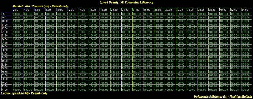
VE Table Axis Scaling
The default values for the MAP axis of the VE table is in 2 psia steps up to a maximum of 44 psia and the default values
for the RPM axis is in 350 RPM steps up a max of 7700 RPM. You need to make sure that the maximum values are
enough for the max MAP and RPM that the motor will likely see. When either RPM or MAP exceeds their corresponding
max axis values, the ECU will continue to use the VE values in the last row (or column). If you need to make a change,
simply re-scale the axis values and reflash those changes to the ECU. Keep in mind that the MAP axis is in units of
manifold absolute pressure, not relative pressure. If you wish to determine the corresponding relative pressure values
(for reference) simply subtract your barometric pressure from MAP. The barometric pressure can be read via the
“Barometric Pressure” monitor. If you are at/near sea level (barometric pressure around 14.7 psi) and you wish to
quickly determine the relative pressure in your head, simply subtract 15 psi from the MAP axis value you are looking at
Copyright © 2012 Cobb Tuning Products, LLC. All Rights Reserved
Page 15(for example, 30 psia – 15 psi = 15 psig). This will give you a quick approximation when you wish to think in terms of
relative pressure.
Reflash Changes
Make sure you save this map with the initial changes and reflash to the car before continuing with the tune.
Tuning SD – Starting Values for the VE Table
The default values for the VE table are set to 100% across the entire table. This is not meant to be a starting point to
run the vehicle in SD mode and tune. Instead, you want to consider coming up with initial values in the VE table that
are reasonable enough to run the car in SD mode. The following gives suggestions based on whether or not there is a
functional MAF sensor installed in the car.
Car with Working and Accurate MAF Sensor
If the car has a properly functioning and calibrated MAF sensor installed, you can use the “SD VE Estimated (MAF)”
monitor to aid in determining starting values for your VE table. If there are issues with the accuracy of the MAF sensor
(and resulting airflow calculation) or problems with the IAT sensor, MAP sensor, and/or engine displacement inputs,
this will impact the accuracy of the estimated VE monitor. Also, because MAF sensor-based airflow tends to be
overestimated on throttle tip-in and underestimated on throttle tip-out, the estimated VE monitor will also be
inaccurate during these periods.
The idea here is that you will be tuning your starting VE table while remaining entirely in MAF mode. That is, if the car
you are tuning runs well in MAF mode, you can get a decent initial set-up for the VE table before actually running the
car in SD mode. In addition to the estimated VE monitor, you can also view/log the “SD VE (Commanded)” monitor,
which is the current VE table look-up. This is VE based on the VE table that would be used in the SD airflow calculation
if SD mode was active. By comparing the estimated VE and commanded VE, you can tweak the VE table appropriately.
Keep in mind that the estimated VE monitor is not a substitution for actually tuning the VE table in SD mode based on
actual fueling.
There are a handful of methods you can use to take advantage of the estimated VE monitor in order to come up your
starting VE tune in MAF mode. You may find some or all of these are useful, depending on what tools you have
available and the time you have to spend with the vehicle:
• Data logging – One way to come up with reasonable initial VE values for specific MAP and RPM areas of the VE
table is via data logging. You’ll need to at least log the “SD VE Estimated (MAF)”, “Manifold Abs. Pressure”,
“Engine Speed”, and “Throttle Position” monitors. Logging throttle position will allow you to filter out the
inaccurate estimated VE values when throttle is rapidly changing (ex. during tip-in and tip-out). With data
logging, the more data points you have for a given MAP/RPM range, the more accurate your estimation of VE
will be as it will allow you to throw out more extreme values. But, you should keep your starting VE values
towards the higher side to reduce the chances of a VE error in the starting map resulting in a lean condition
when you start to tune in SD mode. Keep in mind that if the IAT sensor becomes heat soaked, which may occur
with extended idling and stop and go driving, the estimated VE monitor will overestimate VE compared to
actual. You may want to also log “Intake Temperature” and “Vehicle Speed” so you can see if there’s any
relationship between a higher estimated VE and the conditions that may result in a heat soaked IAT sensor. As
you accumulate data, modify the VE table appropriately and then add the “SD VE (Commanded)” monitor for
additional logging. You can then compare your table VE to estimated VE so you can tweak VE further.
Copyright © 2012 Cobb Tuning Products, LLC. All Rights Reserved
Page 16• Steady-state tuning on dyno – If you are tuning on a load-bearing dyno, you can also hold cells of the VE
table and come up with an initial VE for a given cell based on the estimated VE monitor. This would be
accomplished by enabling live tracing on the table and taking advantage of real-time tuning. As you view the
estimated VE monitor, it will show a range of values as the inputs to this calculation rapidly change. Try to use
the highest reasonable value shown. It is not realistic to attempt to do this for every cell of the table just for an
initial VE pre-tune. But, you could focus on, for example, the RPM row that is likely to be closest to peak torque
and, therefore, where VE is likely to be highest (for a given MAP column).
• Filling in the blanks – Depending on the time available for the tune, it may not be feasible to try to estimate
the majority of the cells in the VE table using the methods described above. Instead, you can focus on more
narrow portions of the map representing low, mid and high MAP areas and then “fill in the blanks” between
these areas. Generally speaking, as MAP increases, VE also increases. Also, as it relates to RPM, VE will tend to
follow the torque curve of the motor, generally peaking at the same RPM as the peak torque of the motor.
These are not hard and fast rules, but they are sufficient enough to allow you to interpolate between the areas
of the map you have worked on for the starting VE tune. Keep in mind that the WOT area of the VE table (i.e.
high MAP) is going to be the most crucial area of your pre-tune. This is because load errors at high MAP have
the most potential to cause engine damage. You do not want your first WOT pull in SD mode to result in an
overly lean condition with more timing advance than anticipated. This is also a reason to go with more
conservative fuel and timing maps until you get the VE table dialed-in after switching to SD mode.
Once you have a reasonable starting VE table, you may want to consider bumping up the values in the entire table just
to make sure your pre-tune is more likely to overestimate VE than to underestimate it.
Car without Viable MAF Sensor Configuration
If the MAF sensor has been removed from the car or is otherwise inaccurate, inoperable or not properly calibrated,
then there is not a means to directly estimate VE for a given car. Over time, however, you will see specific patterns in
the VE table for cars you’ve tuned (for a given set of mods) and setting up a reasonable starting VE table for similar
vehicles will not be difficult. If you have no frame of reference, however, you can start with some general guidelines.
The default values in the VE table will be 100% for all cells. This will be generally too high in the lift-throttle, idle, and
cruise areas (i.e. much too rich). Generally speaking, you may see more like 50%-60% in lift-throttle/idle areas and
60%-80% in cruise areas. Moderate boost may be in the 80%-90% range. Higher boost may be in the 90% to over
100% range. To stay on the conservative side of things with your starting VE table, you want to bias your estimate
towards higher values rather than lower. This will reduce the chance of a lean condition when the table VE is less than
actual VE. This is especially critical at higher boost where a lean condition (and greater timing advance) due to lower
than actual load would be more of a problem.
Copyright © 2012 Cobb Tuning Products, LLC. All Rights Reserved
Page 17Tuning SD – The Tables
“SD Volumetric Efficiency” Table
The “SD Volumetric Efficiency” table is the primary means by which the SD tune is accomplished. Once you have your
starting values configured for this table (as described in the previous section), you can get to the actual tune. You’ll
need to make sure you are in SD mode (1 in the SD mode table) and that the car is at operating temperature. As you
hit the MAP/RPM area corresponding to a given cell, if your wideband o2 (wbo2) sensor reads richer than what the
ECU is targeting, you reduce VE for that cell. If your wbo2 sensor reads leaner than what the ECU is targeting, you
increase VE for that cell. You continue this process until you’ve dialed in as much of the VE table as you can.
The final ECU fueling target can be determined via the “Commanded Fuel Final” monitor. This may be different at times
than your primary open loop fueling map due to additional fueling compensations that come into play, such as post-
start/warm-up enrichment, long-term fuel trims, and others. Also, in closed loop, the ECU is not always targeting 1.0
lambda (i.e. 14.7:1 AFR gas). The “Commanded Fuel Final” will account for all these changes as it is the final fueling
target used to ultimately determine injector pulse width.
You should be aware of when the closed to open loop fueling transition occurs for your tune. When the transition to
open loop happens, you may see a lean or rich spike when the short-term fuel trims are no longer applied if that area
of VE table needs work. You can determine the closed/open loop status via the “Closed/Open Loop Switch” monitor.
If the car has a functional and accurate front o2 sensor, you can also tune VE in closed loop via the short and long-term
fuel trims. Simply add together the “A/F Correction #1” and “A/F Learning #1” monitors and try to get this sum as close
to zero as feasible by manipulating VE. If the sum is positive, the ECU is adding fuel because of a lean condition and
you will need to increase VE. If the sum is negative, the ECU is removing fuel because of a rich condition and you will
need to decrease VE.
You may be tempted to simply manipulate the VE table to hit the fueling target you desire for a given MAP/RPM area
regardless of the commanded fuel final (and the primary open loop fueling table). While this is certainly possible, it
does have a few downsides. First, tuning this way would result in VE values that are not representative of actual. That
is, you could not easily compare them to other tunes. It can be quite useful to compare VE tables across tunes as it
Copyright © 2012 Cobb Tuning Products, LLC. All Rights Reserved
Page 18You can also read