ML255 ELECTROMAGNETIC FLOW METER CONVERTER - MCCROMETER
←
→
Page content transcription
If your browser does not render page correctly, please read the page content below
ML255
    ELECTROMAGNETIC
FLOW METER CONVERTER

                  Installation, Operation and
                         Maintenance Manual

                                   30122-46, Rev. 1.2
                                       May 31, 2018

   Important Information:
   Converter Model Number: ________________________
   Converter Serial Number: _________________________
   Meter Serial Number: ____________________________
   RETAIN THIS MANUAL - DO NOT DISCARD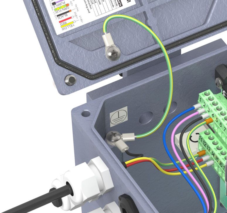
Contents
SAFETY . . . . . . . . . . . . . . . . . . . . . . . . . . . . . . . . . . . . . . . . . . . . . . . . . . . . . . . . . . . . . . . . . . . . . . . . . . . . . . . . . . . .  1
1.0        BATTERY POWERED CONVERTER OVERVIEW . . . . . . . . . . . . . . . . . . . . . . . . . . . . . . . . . . . . . . . . . . . .  2
           1.1        Serial Numbers . . . . . . . . . . . . . . . . . . . . . . . . . . . . . . . . . . . . . . . . . . . . . . . . . . . . . . . . . . . . . . . . . . . . . . . . . . . . . . . . . . .  3
           1.2        Compatible Products  . . . . . . . . . . . . . . . . . . . . . . . . . . . . . . . . . . . . . . . . . . . . . . . . . . . . . . . . . . . . . . . . . . . . . . . . . . . . .  3
2.0        CONVERTER INSTALLATION  . . . . . . . . . . . . . . . . . . . . . . . . . . . . . . . . . . . . . . . . . . . . . . . . . . . . . . . . . . .  4
           2.1        Mounting The Converter . . . . . . . . . . . . . . . . . . . . . . . . . . . . . . . . . . . . . . . . . . . . . . . . . . . . . . . . . . . . . . . . . . . . . . . . . .  4
           2.2        Installing Cables To Converter And Service Loop . . . . . . . . . . . . . . . . . . . . . . . . . . . . . . . . . . . . . . . . . . . . . . . . . . .  4
           2.3        Pulling Sensor Cable Through Electrical Conduit . . . . . . . . . . . . . . . . . . . . . . . . . . . . . . . . . . . . . . . . . . . . . . . . . . .  5
3.0        BATTERY INSTALLATION AND SYSTEM START-UP . . . . . . . . . . . . . . . . . . . . . . . . . . . . . . . . . . . . . . . .  6
           3.1        Battery Life . . . . . . . . . . . . . . . . . . . . . . . . . . . . . . . . . . . . . . . . . . . . . . . . . . . . . . . . . . . . . . . . . . . . . . . . . . . . . . . . . . . . . . .  6
           3.2        Installing Batteries and Starting Up . . . . . . . . . . . . . . . . . . . . . . . . . . . . . . . . . . . . . . . . . . . . . . . . . . . . . . . . . . . . . . . .  6
           3.3        Setting the Time and Date  . . . . . . . . . . . . . . . . . . . . . . . . . . . . . . . . . . . . . . . . . . . . . . . . . . . . . . . . . . . . . . . . . . . . . . . .  6
           3.4        Replacing Batteries . . . . . . . . . . . . . . . . . . . . . . . . . . . . . . . . . . . . . . . . . . . . . . . . . . . . . . . . . . . . . . . . . . . . . . . . . . . . . . .  7
           3.5        Powering-Down and Powering-Up the System . . . . . . . . . . . . . . . . . . . . . . . . . . . . . . . . . . . . . . . . . . . . . . . . . . . . .  8
           3.6        Power Options . . . . . . . . . . . . . . . . . . . . . . . . . . . . . . . . . . . . . . . . . . . . . . . . . . . . . . . . . . . . . . . . . . . . . . . . . . . . . . . . . . . .  8
           3.7        Sampling Frequencies . . . . . . . . . . . . . . . . . . . . . . . . . . . . . . . . . . . . . . . . . . . . . . . . . . . . . . . . . . . . . . . . . . . . . . . . . . . .  9
4.0        SOLAR PANEL OPTION . . . . . . . . . . . . . . . . . . . . . . . . . . . . . . . . . . . . . . . . . . . . . . . . . . . . . . . . . . . . . . . 10
           4.1        Description . . . . . . . . . . . . . . . . . . . . . . . . . . . . . . . . . . . . . . . . . . . . . . . . . . . . . . . . . . . . . . . . . . . . . . . . . . . . . . . . . . . . . . 10
5.0        ELECTRICAL CABLE CONNECTIONS . . . . . . . . . . . . . . . . . . . . . . . . . . . . . . . . . . . . . . . . . . . . . . . . . . . . 11
           5.1        Converter Electrical Cable Connections  . . . . . . . . . . . . . . . . . . . . . . . . . . . . . . . . . . . . . . . . . . . . . . . . . . . . . . . . . . 11
           5.2        Terminal Board . . . . . . . . . . . . . . . . . . . . . . . . . . . . . . . . . . . . . . . . . . . . . . . . . . . . . . . . . . . . . . . . . . . . . . . . . . . . . . . . . . 11
           5.3        FPI Mag 395L Forward Only Cable Connections . . . . . . . . . . . . . . . . . . . . . . . . . . . . . . . . . . . . . . . . . . . . . . . . . . . 13
           5.4        SPI Mag 282L Cable Connection  . . . . . . . . . . . . . . . . . . . . . . . . . . . . . . . . . . . . . . . . . . . . . . . . . . . . . . . . . . . . . . . . . 14
           5.5        Ultra Mag Sensor Cable  . . . . . . . . . . . . . . . . . . . . . . . . . . . . . . . . . . . . . . . . . . . . . . . . . . . . . . . . . . . . . . . . . . . . . . . . . . 15
           5.6        Converter Grounding . . . . . . . . . . . . . . . . . . . . . . . . . . . . . . . . . . . . . . . . . . . . . . . . . . . . . . . . . . . . . . . . . . . . . . . . . . . .17
           5.7        Opto-Isolated Pulse Output Hook-Up  . . . . . . . . . . . . . . . . . . . . . . . . . . . . . . . . . . . . . . . . . . . . . . . . . . . . . . . . . . . . 18
           5.8        Opto-Isolated Pulse Input . . . . . . . . . . . . . . . . . . . . . . . . . . . . . . . . . . . . . . . . . . . . . . . . . . . . . . . . . . . . . . . . . . . . . . . . 18
           5.9        Converter Power Hook-Up . . . . . . . . . . . . . . . . . . . . . . . . . . . . . . . . . . . . . . . . . . . . . . . . . . . . . . . . . . . . . . . . . . . . . . . 19
6.0        CONVERTER START-UP - ALL SENSORS . . . . . . . . . . . . . . . . . . . . . . . . . . . . . . . . . . . . . . . . . . . . . . . . .20
           6.1        Menu Navigation . . . . . . . . . . . . . . . . . . . . . . . . . . . . . . . . . . . . . . . . . . . . . . . . . . . . . . . . . . . . . . . . . . . . . . . . . . . . . . . . 20
           6.2        Front Panel Visualization Pages . . . . . . . . . . . . . . . . . . . . . . . . . . . . . . . . . . . . . . . . . . . . . . . . . . . . . . . . . . . . . . . . . . . 21
           6.3        Factory Set Key Code  . . . . . . . . . . . . . . . . . . . . . . . . . . . . . . . . . . . . . . . . . . . . . . . . . . . . . . . . . . . . . . . . . . . . . . . . . . . . 22
           6.4        Menu Structure . . . . . . . . . . . . . . . . . . . . . . . . . . . . . . . . . . . . . . . . . . . . . . . . . . . . . . . . . . . . . . . . . . . . . . . . . . . . . . . . . . 22
7.0        PROGRAMMING EXAMPLE  . . . . . . . . . . . . . . . . . . . . . . . . . . . . . . . . . . . . . . . . . . . . . . . . . . . . . . . . . . . 25
8.0        MENU 0 - QUICK START . . . . . . . . . . . . . . . . . . . . . . . . . . . . . . . . . . . . . . . . . . . . . . . . . . . . . . . . . . . . . . . 26
9.0        MAIN MENU DESCRIPTIONS . . . . . . . . . . . . . . . . . . . . . . . . . . . . . . . . . . . . . . . . . . . . . . . . . . . . . . . . . . 26
           9.1        Menu 1 - Sensor  . . . . . . . . . . . . . . . . . . . . . . . . . . . . . . . . . . . . . . . . . . . . . . . . . . . . . . . . . . . . . . . . . . . . . . . . . . . . . . . . . 26
           9.2        Menu 2 - Scales . . . . . . . . . . . . . . . . . . . . . . . . . . . . . . . . . . . . . . . . . . . . . . . . . . . . . . . . . . . . . . . . . . . . . . . . . . . . . . . . . . 28
           9.3        Menu 3 - Measure  . . . . . . . . . . . . . . . . . . . . . . . . . . . . . . . . . . . . . . . . . . . . . . . . . . . . . . . . . . . . . . . . . . . . . . . . . . . . . . . 31
           9.4        Menu 4 - Alarms . . . . . . . . . . . . . . . . . . . . . . . . . . . . . . . . . . . . . . . . . . . . . . . . . . . . . . . . . . . . . . . . . . . . . . . . . . . . . . . . . 31
           9.5        Menu 5 - Inputs . . . . . . . . . . . . . . . . . . . . . . . . . . . . . . . . . . . . . . . . . . . . . . . . . . . . . . . . . . . . . . . . . . . . . . . . . . . . . . . . . . 32
           9.6        Menu 6 - Outputs . . . . . . . . . . . . . . . . . . . . . . . . . . . . . . . . . . . . . . . . . . . . . . . . . . . . . . . . . . . . . . . . . . . . . . . . . . . . . . . . 32
           9.7        Menu 7 - Communication . . . . . . . . . . . . . . . . . . . . . . . . . . . . . . . . . . . . . . . . . . . . . . . . . . . . . . . . . . . . . . . . . . . . . . . . 34
           9.8        Menu 8 - Display . . . . . . . . . . . . . . . . . . . . . . . . . . . . . . . . . . . . . . . . . . . . . . . . . . . . . . . . . . . . . . . . . . . . . . . . . . . . . . . . . 34
           9.9        Menu 9 - Data Logger . . . . . . . . . . . . . . . . . . . . . . . . . . . . . . . . . . . . . . . . . . . . . . . . . . . . . . . . . . . . . . . . . . . . . . . . . . . . 35
           9.10       Menu 10 - Diagnostic . . . . . . . . . . . . . . . . . . . . . . . . . . . . . . . . . . . . . . . . . . . . . . . . . . . . . . . . . . . . . . . . . . . . . . . . . . . . 35
           9.11       Menu 11 - Internal Data . . . . . . . . . . . . . . . . . . . . . . . . . . . . . . . . . . . . . . . . . . . . . . . . . . . . . . . . . . . . . . . . . . . . . . . . . . 37
10.0 ALARM MESSAGES . . . . . . . . . . . . . . . . . . . . . . . . . . . . . . . . . . . . . . . . . . . . . . . . . . . . . . . . . . . . . . . . . . . 38
11.0 SPECIFICATIONS . . . . . . . . . . . . . . . . . . . . . . . . . . . . . . . . . . . . . . . . . . . . . . . . . . . . . . . . . . . . . . . . . . . . . 42
12.0 TROUBLESHOOTING GUIDE  . . . . . . . . . . . . . . . . . . . . . . . . . . . . . . . . . . . . . . . . . . . . . . . . . . . . . . . . . . 44
APPENDIX 1.0 UNITS OF MEASURE . . . . . . . . . . . . . . . . . . . . . . . . . . . . . . . . . . . . . . . . . . . . . . . . . . . . . . . . . . 45
APPENDIX 2.0 CONVERSION TABLES . . . . . . . . . . . . . . . . . . . . . . . . . . . . . . . . . . . . . . . . . . . . . . . . . . . . . . . . 46
WARRANTY STATEMENT  . . . . . . . . . . . . . . . . . . . . . . . . . . . . . . . . . . . . . . . . . . . . . . . . . . . . . . . . . . . . . . . . . . . 47

                                                                            3255 WEST STETSON AVENUE • HEMET, CALIFORNIA 92545 USA                                                                Printed In The U.S.A.
                                                                            TEL: 951-652-6811 • 800-220-2279 • FAX: 951-652-3078                                                     Lit. # 30122-46, Rev. 1.2 / 5-31-18
                                                                            Copyright © 2018 McCrometer, Inc. All printed material should not be changed or altered without permission of McCrometer.
                                                                            Any published technical data and instructions are subject to change without notice. Contact your McCrometer representative
      www.mccrometer.com                                                    for current technical data and instructions.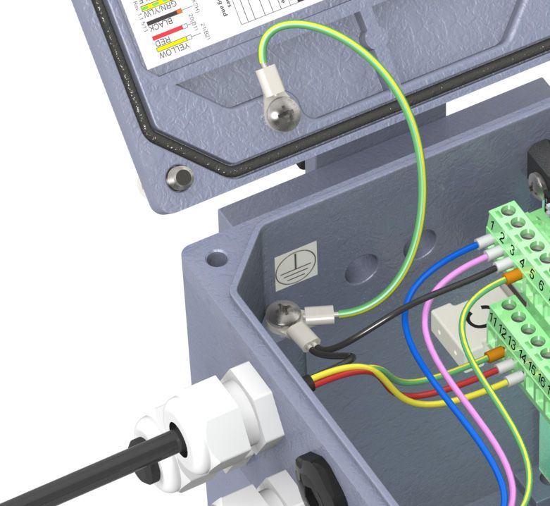
SAFETY
SAFETY
Safety Symbols And Warnings
Throughout this manual are safety warning and caution information boxes. Each warning and caution box will be
identified by a large symbol indicating the type of information contained in the box. The symbols are explained
below:

         !        This symbol indicates important safety information. Failure to follow the instructions can
                  result in serious injury or death.

         i        This symbol indicates important information. Failure to follow the instructions can result in
                  permanent damage to the meter or installation site.

Safety Warnings
When installing, operating, and maintaining McCrometer equipment where hazards may be present, you must
protect yourself by wearing Personal Protective Equipment (PPE) and be trained to enter confined spaces.
Examples of confined spaces are manholes, pumping stations, pipelines, pits, septic tanks, sewage digesters,
vaults, degreasers, storage tanks, boilers, and furnaces.

          WARNING!

    !     Incorrect installation or removal of FPI Mag meters can result in serious injury or death. Read
          the instructions in this manual on the proper procedures carefully.

          WARNING!

    !     Never enter a confined space without testing the air at the top, middle, and bottom of the
          space. The air may be toxic, oxygen deficient, or explosive. Do not trust your senses to determine if
          the air is safe. You cannot see or smell many toxic gases.

          WARNING!

    !     Never enter a confined space without the proper safety equipment. You may need a respirator,
          gas detector, tripod, lifeline, and other safety equipment.

          WARNING!

    !     Never enter a confined space without standby/rescue personnel within earshot. Standby/rescue
          personnel must know what action to take in case of an emergency.

             WARNING!

    !        Pressurized pipes should only be hot tapped, cut, or drilled by qualified personnel. If possible,
             depressurize and drain the pipe before attempting any installation.

             WARNING!

    !        Carefully read all safety warning tags attached to the meter.

              At the end of its lifetime, this product shall be disposed of in full compliance with the
              environmental regulations of the state in which it is located.

                                                                      1
                                        3255 WEST STETSON AVENUE • HEMET, CALIFORNIA 92545 USA                                           Printed In The U.S.A.
                                        TEL: 951-652-6811 • 800-220-2279 • FAX: 951-652-3078                                Lit. # 30122-46 Rev. 1.2 / 5-31-18
                                        Copyright © 2018 McCrometer, Inc. All printed material should not be changed or altered without permission of McCrometer.
                                        Any published technical data and instructions are subject to change without notice. Contact your McCrometer representative
   www.mccrometer.com                   for current technical data and instructions.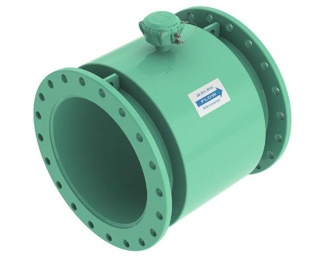
BATTERY POWERED CONVERTER OVERVIEW
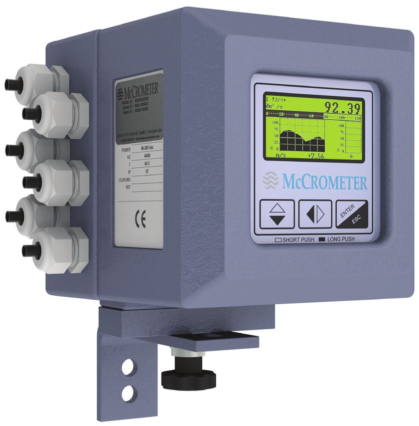
1.0 BATTERY POWERED CONVERTER OVERVIEW
Read this entire manual prior to installation and/or changing any settings. Retain this manual in your records. DO
NOT DISCARD.
The battery powered signal converter is the reporting, input and output control device for the sensor.
The converter allows the measurements, functional programming, control of the sensor and data recording to be
communicated through the front panel and I/O.
The battery powered microprocessor-based signal converter has a twelve-point curve-fitting algorithm to improve
accuracy, an 8-line graphical LCD display with 3 button programming, and a rugged enclosure that meets IP67.
In addition to a menu-driven self-diagnostic test mode, the converter continually monitors the meter's functionality.
The converter will output rate of flow and total volume.
The converter has two digital open drain outputs for monitoring volume or status and a digital switch closure
input.
The converter also comes standard with password protection and many more features.
Mod
el
Seria #: 88
00
Met l #: E12- 03xxx
er #: 34
MI1 567
2-34
56
3255
W.
PH (95 STET
1) 652 SON
-6811 AVE,
• htt HEME
p://ww T, CA
w.m 92
ccrom 545
eter.coUSA
m
R
E C
T S
N E
E
Figure 1. Electronic Converter Dimensions
2
3255 WEST STETSON AVENUE • HEMET, CALIFORNIA 92545 USA Printed In The U.S.A.
TEL: 951-652-6811 • 800-220-2279 • FAX: 951-652-3078 Lit. # 30122-46 Rev. 1.2 / 5-31-18
Copyright © 2018 McCrometer, Inc. All printed material should not be changed or altered without permission of McCrometer.
Any published technical data and instructions are subject to change without notice. Contact your McCrometer representative
www.mccrometer.com for current technical data and instructions.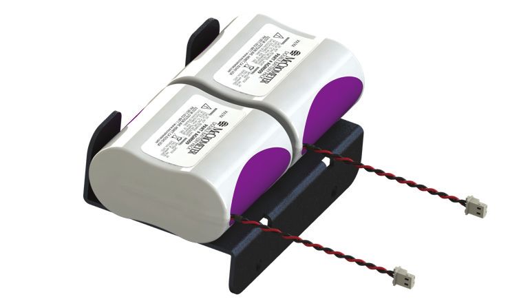
BATTERY POWERED CONVERTER OVERVIEW
    1.1     Serial Numbers
    The converter and sensor are supplied as a matched system. Verify the meter serial numbers on both the converter
    and sensor match. This will ensure a properly calibrated system.
    The tag on the side of the converter has the Converter Model Number, the Converter Serial Number, the Meter
    Model Number and the Meter Serial Number. An example is shown below.

                                                                                       Converter Model: 880003xxx
                            Conve
                            Conve
                            Meter
                            Meter
                                   rter Model
                                   rter SN: : 88000
                                    Model E12-34567
                                                       3xxx
                                                                                       Converter SN: E12-34567
                                                                                       Meter Model: UM08-10
                                          : UM08-
                                    SN: UM201     10
                            http://
                                    www.m 30xxx
                                            ccrom
                                                  eter.co
                                                          m

                                                                                       Meter SN: UM20130xxx
                                                                                       http://www.mccrometer.com

                                                              Figure 2. Converter Serial Number Tag

       IMPORTANT: Verify the Meter Serial Numbers on both the converter and sensor match. This will ensure

i      a properly calibrated system. The Meter Serial Number is located on the side of the sensor, and the
       Converter Serial Number and the Meter Serial Number are located on a label on the side of the converter.
       Ensure the Meter Serial Number on the sensor and the converter tags match.

    1.2     Compatible Products
    The Battery Powered converter works with all UltraMag meters, Full Profile Insertion (FPI) forward flow meters,
    and Single Point Insertion (SPI) meters.

                                                                                                3
                                                                  3255 WEST STETSON AVENUE • HEMET, CALIFORNIA 92545 USA                                           Printed In The U.S.A.
                                                                  TEL: 951-652-6811 • 800-220-2279 • FAX: 951-652-3078                                Lit. # 30122-46 Rev. 1.2 / 5-31-18
                                                                  Copyright © 2018 McCrometer, Inc. All printed material should not be changed or altered without permission of McCrometer.
                                                                  Any published technical data and instructions are subject to change without notice. Contact your McCrometer representative
       www.mccrometer.com                                         for current technical data and instructions.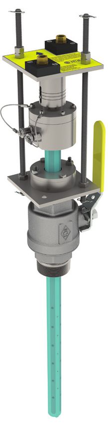
CONVERTER INSTALLATION
2.0     CONVERTER INSTALLATION
2.1     Mounting The Converter
If possible mount the converter in an electronics shed or environmental enclosure. If the converter is mounted
outdoors a sun shield is recommended. The sun shield should be oriented in a direction to reduce sun damage
and ensure readability. The converter is mounted using 2 bolts. See Figure 1. A service loop in the cables is
required. See Section 3.2. This electronic unit is rated IP67 for temporary flooding.

2.2     Installing Cables To Converter And Service Loop
Conduit of any kind CANNOT be attached directly to the electronics enclosure. Attaching conduit directly to the
enclosure will introduce dangerous gasses and moisture into the enclosure creating a dangerous condition, and
will remove the enclosure's IP67 rating. Attaching conduit to the enclosure or altering the enclosure in any
way will void the warranty.
Any cable running through a conduit must exit the conduit and have a minimum of an 8" service loop before
entering the electronics enclosure through the cable glands. All cable compression glands must be properly
tightened to prevent moisture intrusion and maintain the IP67 rating. This allows the electronics enclosure to be
rotated and the rear panel to be accessed. If electrically bonding (grounding) the enclosure to metallic conduit
or raceways, secure a lead wire to the enclosures back panel screw and attach the lead to a listed and approved
conduit grounding bushing. See Figure 3. To insure IP67 rating use only round cable 0.125" to 0.375" in diameter.

!
      WARNING: Do not connect any form of conduit directly to the converter enclosure. Doing so will allow
      moisture and potentially dangerous gasses to enter directly into the converter. Attaching any conduit to
      the enclosure, or altering the enclosure in any way will void the warranty.

                             Power Cable                Enclosure Front                                            Enclosure Back
Conduit Grounding
Bushings
                                                                                             Enclosure
                                                                                             Backplate
                                                                                               Screw

Sensor Cables                                                                        Grounding Lead
 (Showing 8”
Service Loop)

                                         IMPORTANT: All cables must have a minimum 8" service loop.

           Figure 3. Cable Installation, A Service Loop And Bonding To Metallic Conduit

                                                                     4
                                       3255 WEST STETSON AVENUE • HEMET, CALIFORNIA 92545 USA                                           Printed In The U.S.A.
                                       TEL: 951-652-6811 • 800-220-2279 • FAX: 951-652-3078                                Lit. # 30122-46 Rev. 1.2 / 5-31-18
                                       Copyright © 2018 McCrometer, Inc. All printed material should not be changed or altered without permission of McCrometer.
                                       Any published technical data and instructions are subject to change without notice. Contact your McCrometer representative
    www.mccrometer.com                 for current technical data and instructions.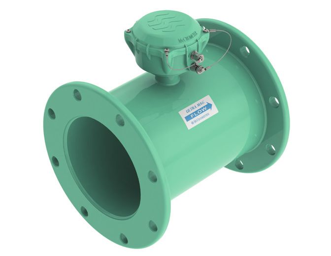
CONVERTER INSTALLATION
    2.3      Pulling Sensor Cable Through Electrical Conduit
    It is very important to protect the end of the sensor cable when pulling it through a conduit. Water can accumulate
    in low portions of conduit. Always use the factory supplied cable cover, or similar method, to seal the end of the
    cable against water when pulling the cable through conduit. See Figure 4. This will ensure proper operation of
    the meter.

    Pulling The Sensor Cable:
    1. Tie a rope or cable-snake securely around the middle of the cable cover.
    2. Carefully pull the rope or snake until the sensor cable end clears the conduit.
    3. Bring the cable end to the converter location. If necessary, secure the cable so that it does
       not fall back through the conduit.
    4. Remove the cable cover by pulling the rip wire. The cable cover will tear off (discard the cover).

i   CAUTION: Do not cut the cable cover off. Doing so may damage the sensor cable and adversely effect the
    calibration of the meter.

                                                                                     Rip Wire

                                                                     Cable Cover

                        Secure rope or snake to this
                                                                                   Sensor Cable
                            area of the cable cover

                                                     Figure 4. Cable Cover

                                                                           5
                                             3255 WEST STETSON AVENUE • HEMET, CALIFORNIA 92545 USA                                           Printed In The U.S.A.
                                             TEL: 951-652-6811 • 800-220-2279 • FAX: 951-652-3078                                Lit. # 30122-46 Rev. 1.2 / 5-31-18
                                             Copyright © 2018 McCrometer, Inc. All printed material should not be changed or altered without permission of McCrometer.
                                             Any published technical data and instructions are subject to change without notice. Contact your McCrometer representative
       www.mccrometer.com                    for current technical data and instructions.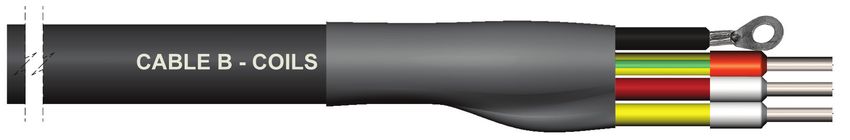
BATTERY INSTALLATION AND SYSTEM START-UP
3.0       BATTERY INSTALLATION AND SYSTEM START-UP
3.1       Battery Life
The estimated battery life with standard use and recommended sampling frequency (see section 3.7) is 3-5 years.
Additionally, there is a battery life calculator available to estimate battery life in your specific application. Contact
your local McCrometer representative or the McCrometer technical support team for a consultation on battery life.

3.2       Installing Batteries and Starting Up
Follow this procedure if you are installing batteries in the unit for the first time. If you are replacing batteries,
go to section 3.4, "Replacing Batteries".

Note:     Ensure there is no power connected externally and that the battery DIP switches are in the OFF position.
1.    Remove the battery holder from the ML255 converter by removing the two screws and lock washers holding
      it in place.
2.    Place two double battery packs (part number AGM009) on the ML255 battery holder as shown in Figure 5.
3.    Secure new battery packs to the battery holder using tie
      wraps.
4.    Re-install the battery holder into the converter using the
      previously removed screws and washers.
5.    Plug the battery pack connectors into the B1 and B2
      sockets on the main board.
6.    Wait one minute.
7.    Move battery DIP switch B1/B2 to ON. The converter will
      begin booting and the red CPU LED will turn on solid. It
      will then begin flashing after it completes booting. Booting
      may take 2-3 minutes.                                                                        Figure 5. ML255 batteries

3.3       Setting the Time and Date
Each time the ML255 is powered up, the time and date need to be set immediately after the system finishes
initialization because it does not retain time information when it is powered down. The correct time setting is
necessary for data logging and event logging functions.
1.    Allow the converter to complete its initialization sequence.
2.    Press the Enter button to open the Quick Start menu. If the Quick Start menu is not enabled, skip step 3.
3.    Navigate to the Main Menu using the Up/Down arrow key and press Enter.
4.    Enter your level 2 access code (default is 000002) and press Enter.
5.    Navigate to 9-Data logger with the Up/Down arrow key and press Enter.
6.    Press Enter to edit the date and time.
7.    Using the Right/Left arrow key to navigate and the Up/Down arrow key to change the data, enter the date
      and time. Press Enter to accept the date and time.
8.    Long press the Enter key twice to return to the main display.

                                                                        6
                                          3255 WEST STETSON AVENUE • HEMET, CALIFORNIA 92545 USA                                           Printed In The U.S.A.
                                          TEL: 951-652-6811 • 800-220-2279 • FAX: 951-652-3078                                Lit. # 30122-46 Rev. 1.2 / 5-31-18
                                          Copyright © 2018 McCrometer, Inc. All printed material should not be changed or altered without permission of McCrometer.
                                          Any published technical data and instructions are subject to change without notice. Contact your McCrometer representative
     www.mccrometer.com                   for current technical data and instructions.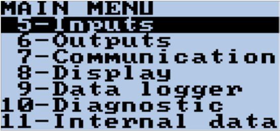
BATTERY INSTALLATION AND SYSTEM START-UP
3.4        Replacing Batteries
Contact your local McCrometer representative or McCrometer Customer Service (customerservice@mccrometer.
com) to order replacement batteries.
1. Power down the system.
      a.   If there is external power applied to the converter, unplug it.
      b.   Press the Enter/Esc button for one second to turn on the front panel display.
      c.   Press the Enter/Esc button again to display the menus.
      d.   Select Main Menu and press Enter.
      e.   Enter the L2 access code.
      f.   Navigate to menu 10-Diagnostic and press Enter.
      g.   Select Stand-By and press Enter.
      h.   Long press Enter to execute. The display will indicate "Stand-By" momentarily and then go blank.
      i.   Move battery DIP switch B1/B2 to OFF.
The unit is now safely powered down.

2. Remove the batteries.
      a.   Disconnect the battery connectors from the B1 and B2 sockets on the Main Board.
      b.   Remove the two screws securing the battery holder to the converter housing.
      c.   Remove the holder from the converter.

3. Installing Batteries:
      a.   Remove the battery holder from the ML255 converter by removing the two screws and lock washers
           holding it in place.
      b.   Cut the tie wraps from the batteries and dispose of the battery packs.
      c.   Secure new battery packs to the battery holder using tie wraps.
      d.   Re-install the battery holder into the converter using the previously removed screws and washers.
      e.   Plug the battery pack connectors into the B1 and B2 sockets on the main board.

4. Power up the system.
      a.   Wait one minute after plugging in the battery pack connectors.
      b.   Move battery DIP switch B1/B2 to ON.
      c.   The converter will begin powering up and the red CPU LED will turn on solid. It will then begin flashing
           after it completes booting.
Note: Powering up may take two to three minutes.

                                                                         7
                                           3255 WEST STETSON AVENUE • HEMET, CALIFORNIA 92545 USA                                           Printed In The U.S.A.
                                           TEL: 951-652-6811 • 800-220-2279 • FAX: 951-652-3078                                Lit. # 30122-46 Rev. 1.2 / 5-31-18
                                           Copyright © 2018 McCrometer, Inc. All printed material should not be changed or altered without permission of McCrometer.
                                           Any published technical data and instructions are subject to change without notice. Contact your McCrometer representative
   www.mccrometer.com                      for current technical data and instructions.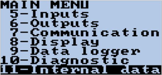
BATTERY INSTALLATION AND SYSTEM START-UP
3.5       Powering-Down and Powering-Up the System
Note: This power-down procedure will only stop the system from operating. If you need to replace the batteries or
prepare the unit for shipping, follow section 3.4.
Powering-Down:
1.    Press the Enter/Esc button for one second to turn on the front panel display.
2.    Press the Enter/Esc button again to display the menus.
3.    Select Main Menu and press Enter.
4.    Enter the L2 access code.
5.    Navigate to menu 10-Diagnostic and press Enter.
6.    Select Stand-By and press Enter.
7.    Long press Enter to execute. The display will indicate Stand-By momentarily and go blank.
The unit is now powered down.

Powering-Up:
1.    Move battery DIP switch B1/B2 to OFF.
2.    Wait one minute.
3.    Move battery DIP switch B1/B2 to ON.
4.    The converter will begin powering up and the red CPU LED will turn on solid. It will then begin flashing after
      it completes booting.
Note: Powering up may take two to three minutes.

3.6       Power Options
Depending on the sampling frequency (described in section 3.7), output options, and specific application position,
you may choose to add additional power options to the battery powered converter. The 5W solar panel option
(described in section 4.0) can extend battery life to 10-15 years. Additionally, you have the option of connecting
external power of 12-60VDC or 100-240VAC.

                                                                        8
                                          3255 WEST STETSON AVENUE • HEMET, CALIFORNIA 92545 USA                                           Printed In The U.S.A.
                                          TEL: 951-652-6811 • 800-220-2279 • FAX: 951-652-3078                                Lit. # 30122-46 Rev. 1.2 / 5-31-18
                                          Copyright © 2018 McCrometer, Inc. All printed material should not be changed or altered without permission of McCrometer.
                                          Any published technical data and instructions are subject to change without notice. Contact your McCrometer representative
     www.mccrometer.com                   for current technical data and instructions.
REAL FLOW PROFILE
BATTERY INSTALLATION AND SYSTEM START-UP
3.7 Sampling Frequencies VARIABLE CONSTANT VARIABLE
The battery powered converter can be programmed to measure in these modes:
Maximum sample rate
CONTINUOUS SAMPLING
Max S.R. Max S.R. Max S.R:
Sample rate at 3 seconds
AVERAGE SAMPLING
3 Sec. 3 Sec. 3 Sec.
Sample rate at 15 seconds
MAX LIFE SAMPLING
15 Sec. 15 Sec. 15 Sec.
S.R.=SAMPLE RATE
Figure 6. Sampling Frequency Modes
Each sampling frequency mode has a different effect on battery life. Note that the battery life shown below is
under optimal conditions:
• Continuous sampling*: < 6 months
• Average sampling**: > 5 years
• Max life sampling: > 7 years
* Note: Continuous sampling is only available if energy saving is turned off.
** Smart sampling: 1-5 years depending on flow profile
9
3255 WEST STETSON AVENUE • HEMET, CALIFORNIA 92545 USA Printed In The U.S.A.
TEL: 951-652-6811 • 800-220-2279 • FAX: 951-652-3078 Lit. # 30122-46 Rev. 1.2 / 5-31-18
Copyright © 2018 McCrometer, Inc. All printed material should not be changed or altered without permission of McCrometer.
Any published technical data and instructions are subject to change without notice. Contact your McCrometer representative
www.mccrometer.com for current technical data and instructions.SOLAR PANEL OPTION
4.0 SOLAR PANEL OPTION 310 mm
12 ¼”
4.1 Description
193 mm
The solar panel provides power to the converter by
7 ½”
converting sunlight into electrical energy to recharge
the solar panels' rechargeable battery. Its nominal power
output is 5W. The solar panel comes complete with all
accessories, except for the fixing rod.
295 mm
11 ½”
193 mm
7 ½”
50 mm
2“
Figure 7. Solar panel dimensions
Solar panel plugs into
circuit board HERE
Figure 8. Plug location for solar panel
10
3255 WEST STETSON AVENUE • HEMET, CALIFORNIA 92545 USA Printed In The U.S.A.
TEL: 951-652-6811 • 800-220-2279 • FAX: 951-652-3078 Lit. # 30122-46 Rev. 1.2 / 5-31-18
Copyright © 2018 McCrometer, Inc. All printed material should not be changed or altered without permission of McCrometer.
Any published technical data and instructions are subject to change without notice. Contact your McCrometer representative
www.mccrometer.com for current technical data and instructions.ELECTRICAL CABLE CONNECTIONS
5.0 ELECTRICAL CABLE CONNECTIONS
5.1 Converter Electrical Cable Connections
CAUTION - Always disconnect the power cord before attempting any electrical connections.
All electrical cables enter the converter through compression fittings located on the side of the converter. Ensure
that all compression glands are properly tightened and all unused fittings are plugged so the case remains sealed.
5.2 Terminal Board
All connections are made on the terminal board. To access the terminal board, loosen the four screws on the back
of the converter to remove the rear cover.
NOTE: The terminal blocks unplug from the circuit board for easy connection.
External power
12-60VDC or 100-
240VAC connector
block battery socket
M1 connector block
IF2X socket
DIP switch for
SD memory card keyboard block
Figure 9. Terminal Board Inputs, Outputs, and Other Components
11
3255 WEST STETSON AVENUE • HEMET, CALIFORNIA 92545 USA Printed In The U.S.A.
TEL: 951-652-6811 • 800-220-2279 • FAX: 951-652-3078 Lit. # 30122-46 Rev. 1.2 / 5-31-18
Copyright © 2018 McCrometer, Inc. All printed material should not be changed or altered without permission of McCrometer.
Any published technical data and instructions are subject to change without notice. Contact your McCrometer representative
www.mccrometer.com for current technical data and instructions.ELECTRICAL CABLE CONNECTIONS
The sensor, hardwired inputs and outputs are connected to the converter through three terminal blocks. To locate
the terminal blocks, remove the rear cover plate, removing the four screws (5mm Allen key). When the cover is
removed, the terminal blocks are visible as shown in the figure above. These terminal are the converter hardwire
connections to the external equipment, including the sensor.
The following figure shows numbering and the respective connecting of the sensor cables, and input/outputs.
FORWARD ELECTRODES INPUT
E1 E2 C SH + -
1 2 3 4 5 6 7 8 9 10
11 12 13 14 15 16 17
SH C1 C2
SH B1 B2 E
OUT1 OUT2 OUT1 OUT2
COILS OPEN COMMON
COLLECTOR
Figure 10. Terminal Board Descriptions
12
3255 WEST STETSON AVENUE • HEMET, CALIFORNIA 92545 USA Printed In The U.S.A.
TEL: 951-652-6811 • 800-220-2279 • FAX: 951-652-3078 Lit. # 30122-46 Rev. 1.2 / 5-31-18
Copyright © 2018 McCrometer, Inc. All printed material should not be changed or altered without permission of McCrometer.
Any published technical data and instructions are subject to change without notice. Contact your McCrometer representative
www.mccrometer.com for current technical data and instructions.ELECTRICAL CABLE CONNECTIONS
5.3 FPI Mag 395L Forward Only Cable Connections
Black Ground
To Chassis Lug Terminal Block Assignments
Cable Terminal Wire Color Connected To
WIRING 395L/395LC
Right Sensing
A #1 (E1) Blue
electrodes
CONVERTER
Left Sensing
1 2 3 4 11 12 13
8/16
A #2 (E2) Pink
Electrodes
ML255
CHASSIS | BLACK
RED
YELLOW
BLUE
PINK
BLACK
GREEN/YELLOW
GREEN/YELLOW
Reference
p/n 17136 Rev. 1.0
A #3 (C) Black
Ground
Cable Shield
A #4 (SH) Green/Yellow
Ground
Ground To
B Chassis Lug Black
Chassis Lug*
Cable Shield
B #11 (SH) Green/Yellow
Ground
B #12 (B1) Red Coil
B #13 (B2) Yellow Coil
`
*IMPORTANT: See Section 5.6.1, "Converter Grounding
i For FPI Mag 395L and Ultra Mag Body Style 2", Figure 15
for instructions on attaching the chassis ground wire to
the converter ground lug.
Cable Diameters:
Cable A (15035): 0.248”
Cable B (15036): 0.248”
FPI Sensor
Figure 11. FPI Mag 395L Sensor Cable Connections
13
3255 WEST STETSON AVENUE • HEMET, CALIFORNIA 92545 USA Printed In The U.S.A.
TEL: 951-652-6811 • 800-220-2279 • FAX: 951-652-3078 Lit. # 30122-46 Rev. 1.2 / 5-31-18
Copyright © 2018 McCrometer, Inc. All printed material should not be changed or altered without permission of McCrometer.
Any published technical data and instructions are subject to change without notice. Contact your McCrometer representative
www.mccrometer.com for current technical data and instructions.ELECTRICAL CABLE CONNECTIONS
5.4 SPI Mag 282L Cable Connection
Terminal Block Assignments
Terminal Wire Color Connected To
WIRING SPI 282L
Sensing
#1 Blue
CONVERTER
electrode
1 2 3 4 11 12 13 Sensing
p/n 17137 Rev. 1.0 8/16
#2 White
electrode
ML255
Reference
WHITE
BLUE
BLACK
BLACK
RED
YELLOW
#3 Black
ground
Magnet shield
#11 Black / overall cable
shield
#12 Red Coil
#13 Yellow Coil
SPI Sensor
Cable Diameter:
Single Cable (36002): 0.250”
Figure 12. SPI Mag 282L Sensor Cable Connections
14
3255 WEST STETSON AVENUE • HEMET, CALIFORNIA 92545 USA Printed In The U.S.A.
TEL: 951-652-6811 • 800-220-2279 • FAX: 951-652-3078 Lit. # 30122-46 Rev. 1.2 / 5-31-18
Copyright © 2018 McCrometer, Inc. All printed material should not be changed or altered without permission of McCrometer.
Any published technical data and instructions are subject to change without notice. Contact your McCrometer representative
www.mccrometer.com for current technical data and instructions.ELECTRICAL CABLE CONNECTIONS
5.5 Ultra Mag Sensor Cable
5.5.1 Ultra Mag Body Style 1 - 2", 3" And 14+"
Black Ground
To Chassis Lug
Terminal Block Assignments
Cable Terminal Wire Color Connected To
WIRING UM/MX
Right Sensing
CONVERTER
A #1 (E1) Blue
electrodes
1 2 3 4 11 12 13
8/16
Left Sensing
ML255
A #2 (E2) Pink
BLUE
PINK
BLACK JUMPER
GREEN/YELLOW
CHASSIS | BLACK
GREEN/YELLOW
RED
YELLOW
Electrodes
p/n 17134 Rev. 1.0
Reference
B #3 (C) Black
Ground
Cable Shield
A #4 (SH) Green/Yellow
Ground
Ground To
B Chassis Lug Black
Chassis Lug*
Cable Shield
B #11 (SH) Green Yellow
Ground
B #12 (B1) Red Coil
B #13 (B2) Yellow Coil
`
*IMPORTANT: See Section 5.6.2, "Converter Grounding
i For Ultra Mag Body Style 1", Figure 16 for instructions
on attaching the chassis ground wire to the converter
ground lug.
Shrink Tube
CABLE A - ELECTRODES
CABLE B - COILS
Cable Diameters:
Cable A (15035): 0.248”
Cable B (15036): 0.248”
Ultra Mag Body Style 1 -
2", 3" and 14+"
Cable Jacket
Figure 13. Ultra Mag Body Style 1
Sensor Cable Connections
15
3255 WEST STETSON AVENUE • HEMET, CALIFORNIA 92545 USA Printed In The U.S.A.
TEL: 951-652-6811 • 800-220-2279 • FAX: 951-652-3078 Lit. # 30122-46 Rev. 1.2 / 5-31-18
Copyright © 2018 McCrometer, Inc. All printed material should not be changed or altered without permission of McCrometer.
Any published technical data and instructions are subject to change without notice. Contact your McCrometer representative
www.mccrometer.com for current technical data and instructions.ELECTRICAL CABLE CONNECTIONS
5.5.2 Ultra Mag Body Style 2 - 4" through 12"
Black Ground
To Chassis Lug
Terminal Block Assignments
WIRING UMII/UMXII
Cable Terminal Wire Color Connected To
CONVERTER
1 2 3 4 11 12 13
8/16
Right Sensing
A #1 (E1) Blue
ML255
electrodes
CHASSIS | BLACK
RED
YELLOW
BLUE
PINK
BLACK
GREEN/YELLOW
GREEN/YELLOW
p/n 17135 Rev. 1.0
Left Sensing
A #2 (E2) Pink
Electrodes
Reference
A #3 (C) Black
Ground
Cable Shield
A #4 (SH) Green/Yellow
Ground
Ground To
B Chassis Lug Black
Chassis Lug*
Cable Shield
B #11 (SH) Green Yellow
Ground
B #12 (B1) Red Coil
B #13 (B2) Yellow Coil
`
*IMPORTANT: See Section 5.6.1, "Converter Grounding
i For FPI Mag 395L and Ultra Mag Body Style 2", Figure 15
for instructions on attaching the chassis ground wire to
the converter ground lug.
Shrink Tube
CABLE A - ELECTRODES
Cable Diameters:
CABLE B - COILS
Cable A (15035): 0.248”
Cable B (15036): 0.248”
Cable Jacket Ultra Mag Body Style 2 - 4" - 12"
Figure 14. Ultra Mag Body Style 2 Sensor
Cable Connections
16
3255 WEST STETSON AVENUE • HEMET, CALIFORNIA 92545 USA Printed In The U.S.A.
TEL: 951-652-6811 • 800-220-2279 • FAX: 951-652-3078 Lit. # 30122-46 Rev. 1.2 / 5-31-18
Copyright © 2018 McCrometer, Inc. All printed material should not be changed or altered without permission of McCrometer.
Any published technical data and instructions are subject to change without notice. Contact your McCrometer representative
www.mccrometer.com for current technical data and instructions.ELECTRICAL CABLE CONNECTIONS
5.6 Converter Grounding
5.6.1 Converter Grounding For FPI Mag 395L and Ultra Mag Body Style 2
On converters attached to the
395L and Ultra Mag body style 2
flow meters, the sensor cable has
a ground wire fitted with a loop.
Attach the wire with the loop to the
enclosure's ground terminal lug as
shown in Figure 15. Enclosure
Ground Lug
Black Ground
Cable B Wire With Loop
From Cable B
Figure 15. Converter Grounding With Cable Lug For FPI
Mag 395L and Ultra Mag Body Style 2
5.6.2 Converter Grounding For Ultra Mag Body Style 1
On converters attached to the Ultra
Mag body style 1 flow meters, the
sensor cable has a ground wire fitted
with a loop and a terminal extension.
Attach the wire to the enclosure's
ground terminal lug as shown in Enclosure
Figure 16 via the wire end loop, Ground Lug
then connect the wire extension to
Terminal #3.
Black Ground
Cable B Wire With Loop
From Cable B
With Lead To
Terminal #3
Figure 16. Converter Grounding With Cable Lug For FPI Mag
395L and Ultra Mag Body Style 1
17
3255 WEST STETSON AVENUE • HEMET, CALIFORNIA 92545 USA Printed In The U.S.A.
TEL: 951-652-6811 • 800-220-2279 • FAX: 951-652-3078 Lit. # 30122-46 Rev. 1.2 / 5-31-18
Copyright © 2018 McCrometer, Inc. All printed material should not be changed or altered without permission of McCrometer.
Any published technical data and instructions are subject to change without notice. Contact your McCrometer representative
www.mccrometer.com for current technical data and instructions.ELECTRICAL CABLE CONNECTIONS
5.7 Opto-Isolated Pulse Output Hook-Up
Both outputs are open drain outputs used to communicate with external devices.
• Maximum switching voltage: 40 VDC
• Maximum switching current: 100mA
• Maximum Ron = 70Ω
• Maximum switching frequency (load RL=240Ω, VOUT=24VDC): 50Hz
• Isolation: 500 V
i
IMPORTANT
Outputs are not isolated from each other. All outputs MUST use the same power source.
OPTO ISOLATED OUTPUTS
OUT 1
15
OUT 2
16
COMMON EMITTER
17
Figure 17. Opto-Isolated Pulse Output Diagram
5.8 Opto-Isolated Pulse Input
• Opto-isolated pulse input
• 500 V isolation
• 3-40 VDC on voltage
• Input programming per input menu, will perform functions set to ON.
Input example:
Push button
switch
10K +
5 3-40 VDC
24V
-
6
Figure 18. Opto-Isolated Pulse Input Diagram
18
3255 WEST STETSON AVENUE • HEMET, CALIFORNIA 92545 USA Printed In The U.S.A.
TEL: 951-652-6811 • 800-220-2279 • FAX: 951-652-3078 Lit. # 30122-46 Rev. 1.2 / 5-31-18
Copyright © 2018 McCrometer, Inc. All printed material should not be changed or altered without permission of McCrometer.
Any published technical data and instructions are subject to change without notice. Contact your McCrometer representative
www.mccrometer.com for current technical data and instructions.ELECTRICAL CABLE CONNECTIONS
5.9 Converter Power Hook-Up
!
WARNING!
Hazardous supply voltage can shock, burn, or cause death.
The power supply line must be equipped with external surge protection for current overload (fuse or circuit breaker
with limiting capacity not greater than 10A). It must be easily accessible for the operator and clearly identified.
Power connection is made using the power terminal block on the upper right side of the terminal board.
NOTE: The terminal block uplugs from the circuit board for easy connection. Connect earth ground to the
protective grounding terminal before making other connections. The power supply of this converter is 100 - 240
VAC, 44 - 66 Hz at maximum 4 W or 12-60 VDC.
Neutral Wire
Typically A
White Wire Negative Wire
Line Wire Ground Wire Positive Wire Ground Wire
Typically A Typically A Typically A
Black Wire Green Wire Green Wire
L N + -
Figure 19. AC Power Supply Terminal Block Figure 20. DC Power Supply Terminal
Block
19
3255 WEST STETSON AVENUE • HEMET, CALIFORNIA 92545 USA Printed In The U.S.A.
TEL: 951-652-6811 • 800-220-2279 • FAX: 951-652-3078 Lit. # 30122-46 Rev. 1.2 / 5-31-18
Copyright © 2018 McCrometer, Inc. All printed material should not be changed or altered without permission of McCrometer.
Any published technical data and instructions are subject to change without notice. Contact your McCrometer representative
www.mccrometer.com for current technical data and instructions.CONVERTER START-UP - ALL SENSORS
6.0 CONVERTER START-UP - ALL SENSORS
Before starting up the converter please verify the following:
• Power supply voltage must correspond to that specified on the data plate (located on the side of the converter)
• Electric connections must be wired as described in this manual
• Ground connections must be properly installed
When the converter is powered it initiates a verification cycle of the converter. During the verification cycle the
converter displays an incrementing diagnostic number. When the diagnostic is complete, if an error is found,
an error number will be displayed referencing the chart at the back of this manual. A text message will also be
displayed on the alarm screen.
NOTE: To view alarms, press the RIGHT arrow key from the main display screen.
6.1 Menu Navigation
To navigate through the menus on the converter, the keys on the keypad use the following conventions:
Key: Function:
UP/DOWN KEY (for moving cursor up or down)
SHORT PRESSING (< 1 SECOND):
Moves the cursor up to the previous subject on the menu
Increases the numeric figure of the parameter highlighted by the cursor
Up/Down LONG PRESSING (> 1 SECOND):
Key Moves the cursor down to the next subject on the menu
Decreases the numeric figure of the parameter highlighted by the cursor
RIGHT/LEFT KEY (for moving cursor right or left)
SHORT PRESSING (< 1 SECOND):
Moves the cursor to the right on the input field Note: Push and hold for
Moves the cursor to the following subject of the menu eight seconds to cycle
Changes the display of the process data through contrast settings.
Right/Left
Key LONG PRESSING (> 1 SECOND):
Moves the cursor to the left on the input field
Moves the cursor to the previous subject on the menu
ENTER/ESC KEY (for changing settings)
SHORT PRESSING (< 1 SECOND):
Opens the Quick Start menu for the instrument configuration
TER Enters the selected function
EN C
ES Cancels the selected function under progress
Enter/Esc
Key LONG PRESSING (> 1 SECOND):
Confirms the selected function
Leaves the current menu
Figure 21. Converter Key Conventions
20
3255 WEST STETSON AVENUE • HEMET, CALIFORNIA 92545 USA Printed In The U.S.A.
TEL: 951-652-6811 • 800-220-2279 • FAX: 951-652-3078 Lit. # 30122-46 Rev. 1.2 / 5-31-18
Copyright © 2018 McCrometer, Inc. All printed material should not be changed or altered without permission of McCrometer.
Any published technical data and instructions are subject to change without notice. Contact your McCrometer representative
www.mccrometer.com for current technical data and instructions.CONVERTER START-UP - ALL SENSORS
6.2 Front Panel Visualization Pages
"Visualization pages" are different display screens that present specific information.
If there is screen is in "screen saver" mode, long-press the Left/Right arrow key to wake it up. Short-press the Left/
Right arrow key to cycle through the different visualization pages.
FLOWRATE VALUE / % FULL SCALE
GRAPHIC OF FLOW RATE-TIME
FLOWRATE VALUE / TOTAL AND
BOARD TEMPERATURE ALARMS PARTIAL TOTALIZER OF DIRECT
FLOWRATE VALUE / TOTAL AND
BATTERY STATUS PARTIAL TOTALIZER OF INVERSE
FLOWRATE VALUE / FLOWRATE VALUE / TOTAL AND
% FULL SCALE BARGRAPH PARTIAL NET TOTALIZER
Figure 22. Examples Front Panel Visualization Pages
21
3255 WEST STETSON AVENUE • HEMET, CALIFORNIA 92545 USA Printed In The U.S.A.
TEL: 951-652-6811 • 800-220-2279 • FAX: 951-652-3078 Lit. # 30122-46 Rev. 1.2 / 5-31-18
Copyright © 2018 McCrometer, Inc. All printed material should not be changed or altered without permission of McCrometer.
Any published technical data and instructions are subject to change without notice. Contact your McCrometer representative
www.mccrometer.com for current technical data and instructions.CONVERTER START-UP - ALL SENSORS
6.3 Factory Set Key Code
The converter is delivered with key code L2 = 000002, and with the “Quick start menu” enabled. Press the Enter/
Esc key. The “Quick start menu” is enabled from the section: Menu “8-Display”, section 10.8.
i ATTENTION!
It is very important to record any customized code as it CANNOT be retrieved if it is lost! The converter will
need to be returned to be reset to factory settings.
6.4 Menu Structure
The following is the menu structure for the converter.
NOTE: Some menus change as options are enabled.
!2.UGPUQT!
PF>oo! 11467 1.1 Insert ND of sensor (0-300
MB>! ,13/1111 1.2 Calibration data of sensor v
1.3 Sensors model: Enter the f
Kpu/rqukvkqp>! 1 1.4 Position for insertion senso
Mk>! 2/1111
Mr>! 2/1111 1.5 Factory parameter
M\>! ,111111 1.6 Automatic setting accordin
ME>! 2/1111 1.7 Automatic setting accordin
1.8 Enables the empty pipe de
VE2>ou! 121 1.9 Value of empty pipe sensib
VE3>ou! 112 1.10 Perfom a SENSOR TEST ( s
G/R/fgvgev>! QP 1.11*Enables the automatic zero
G/r/vjt>! 181 1.12 Reset the preceding value
\gtq!ecn/
\gtq!tgu/
!3.UEBNGU! 2.1* Full scale value measure se
2.2* Pulse value on channel 1
Hu>Icn0o! 3611/1 2.3* Duration of the pulse gener
Vgor/w/ogcu/>! úH 2.4* Pulse value on channel 2
Vqv2OW>MIN! 11112 2.5* Duration of the pulse gener
Rnu2>MIN! 2/11111 2.6 Full scale value set for pres
Vrnu2>ou! 1161/1 2.7 Unit of measure of tempera
2.8* Unit of measure and numbe
!4.OGBUWTG 3.1 Low flow zero threshold: 0-
Ewv.qhh>&! 14/1 3.2* Consumption profiles
Rtqh!>! OBZ!NKHG
Fcorkpi>! QHH
4.1 Maximum value alarm set fo
4.2 Minimum value alarm set fo
4.3 Maximum value alarm set fo
4.4 Minimum value alarm set fo
!5.BNBTOU 4.5 Maximum value alarm set fo
Bn/ocz,>&! 111 4.6 Minimum value alarm set fo
4.7 Maximum value alarm set fo
Bn/okp,>&! 111 4.6 Minimum value alarm set fo
Bn/ocz.>&! 22 111 4.7 Maximum value alarm set fo
3255 WESTBn/okp.>&!
STETSON AVENUE • HEMET, CALIFORNIA 111 92545 USA Printed4.8
In TheMinimum
U.S.A. value alarm set fo
J{uv/>&!
TEL: 951-652-6811 14
• 800-220-2279 • FAX: 951-652-3078 Lit. # 30122-46 Rev.4.9 Hysteresis threshold set for
1.2 / 5-31-18
Copyright © 2018 McCrometer, Inc. All printed material should not be changed or altered without permission of McCrometer.
Any published technical data and instructions are subject to change without notice. Contact your McCrometer representative
www.mccrometer.com for current technical data and instructions.!4.OGBUWTG 3.1 Low flow zero threshold: 0-
Ewv.qhh>&! 14/1 3.2* Consumption profiles
Rtqh!>! OBZ!NKHG
Fcorkpi>! QHH
CONVERTER START-UP - ALL SENSORS
4.1 Maximum value alarm set fo
4.2 Minimum value alarm set fo
4.3 Maximum value alarm set fo
4.4 Minimum value alarm set fo
!5.BNBTOU 4.5 Maximum value alarm set fo
Bn/ocz,>&! 111 4.6 Minimum value alarm set fo
4.7 Maximum value alarm set fo
Bn/okp,>&! 111 4.6 Minimum value alarm set fo
Bn/ocz.>&! 111 4.7 Maximum value alarm set fo
Bn/okp.>&! 111 4.8 Minimum value alarm set fo
J{uv/>&! 14 4.9 Hysteresis threshold set for
!6.KPRWVU 5.1* Total direct (positive) flow to
V,!tgugv>! QP 5.2* Partial direct (positive) flow
V.!tgugv>! QP 5.3* Total reverse (negative) flow
Eqwpv!nqem>! QHH 5.4* Partial reverse (negative) flo
Bncto>! QHH 5.6 Totalise counting lock comm
Ycmg.wr>! QHH 5.7* Autozero calibration externa
5.8 Alarm from external signal (
5.8* Auto- switch on command
!7.QWVRWVU
Qwv2>! RNU, 6.1* Output 1
6.5* Output 2
Qwv3>! QHH 6.6 Power supply of pressure pr
7.1 Choice of the communicatio
7.2 Minimum antenna signal st
7.3 Choice of how to send data
7.4 Choice of when send data l
7.5 Interval of data logger send
7.6 Interval of sending DATA LO
7.7 Send Process data*
!8.EQOOWPKEBVKQP 7.8 Send Alarm*
KH3!rtqv/>! FRR 7.8 Check INCOMING SMS*
7.9 Roaming enable*
7.10 Send Data Logger , instant
7.11 Send EVENTS , instant com
7.12 Send config through e-mail
7.13 Enables clock synchronizati
7.14 Check INCOMING E-MAIL*
* (Communication func
specific manual supplie
8.1 Choice of the language: EN
!9.FKURNB[ 8.2 Time for switch off display
Ncpiwcig! GP 8.3 Visualization of "Quick star
F/vkog>u! 171 8.4 lock of DISPLAY in ONE SPE
Swkem!uvctv>! QP 8.5* Total direct (positive) flow t
8.6* Partial direct (positive) flow
Fkur/nqem>! QHH 8.7* Total reverse (negative) flo
V,!tgugv 8.8* Partial reverse (negative) fl
V.!tgugv
9.1* Date and time set
!9.FKURNB[ 9.2 Set of Time Zone ( Against
Ncpiwcig! GP 9.3* Automatic data logger ena
F/vkog>u! 171 9.4 Data formatted like ML250
Swkem!uvctv>! QP 9.5* choice of single (off) or dou
!:.FBVB!NQIIGT QHH
Fkur/nqem>! 9.6* Interval time 1 for the data
3127018031!!18;42
V,!tgugv 9.7* Interval time 2 for the data
V/|qpg>j! .19/1 9.8 Interval 2 start loggin time
V.!tgugv
Beswkukvkqp>! QP 9.9 Interval 2 stop loggin time
9.10 Enables the sending of dire
Eqor/oqfg>! QP 9.11 Enables the sending of dire
kpv/2!>!24j11o11u
!9.FKURNB[ 9.12 Enables the sending of reve
Nqi!V,>!
Ncpiwcig! QP
GP 9.13 Enables the sending of reve
Nqi!R,>!
F/vkog>u! 171 QP 9.14 Enables the sending of net
Nqv!V.>! 9.15 Enables the sending of net
Swkem!uvctv>! QP 9.16 Enables the sending of flow
Nqi!R.>!
Fkur/nqem>! 23 QHH QP 9.17 Enables the sending of pres
Nqi!PV>!
3255 WESTGZGEWVG@
STETSON AVENUE • HEMET, CALIFORNIA 92545 USA
QP Printed9.18
In TheEnables
U.S.A. the sending of pres
Nqi!PR>!
V.!tgugv
TEL: 951-652-6811 • 800-220-2279 • FAX: 951-652-3078
QP Lit. # 30122-46 Rev.9.19 Enables the sending of diffe
1.2 / 5-31-18
Nqi!S>! QP 9.18 Enables the sending of tem
Copyright © 2018 McCrometer, Inc. All printed material should not be changed or altered without permission of McCrometer.
Any publishedNqi!UVBV>! change without notice. Contact your McCrometer9.20*Loggin
technical data and instructions are subject toQP representative of statistical data
www.mccrometer.com 9.21 Enables the sending of mea
O/wpkvu>!
for current technical data and instructions.
!9.FKURNB[ QP 9.22 Enables the sending of mea
&!xcnwgu>!
Ncpiwcig! QHH GP 9.23 Symbol used as separator o!9.FKURNB[ 8.2 Time for switch off display
Ncpiwcig! GP 8.3 Visualization of "Quick star
F/vkog>u! 171 8.4 lock of DISPLAY in ONE SPE
Swkem!uvctv>! QP 8.5* Total direct (positive) flow t
8.6* Partial direct (positive) flow
CONVERTER START-UP - ALL SENSORS
Fkur/nqem>!
V,!tgugv
QHH 8.7* Total reverse (negative) flo
8.8* Partial reverse (negative) fl
V.!tgugv
9.1* Date and time set
!9.FKURNB[ 9.2 Set of Time Zone ( Against
Ncpiwcig! GP 9.3* Automatic data logger ena
F/vkog>u! 171 9.4 Data formatted like ML250
Swkem!uvctv>! QP 9.5* choice of single (off) or dou
!:.FBVB!NQIIGT QHH
Fkur/nqem>! 9.6* Interval time 1 for the data
3127018031!!18;42
V,!tgugv 9.7* Interval time 2 for the data
V/|qpg>j! .19/1 9.8 Interval 2 start loggin time
V.!tgugv
Beswkukvkqp>! QP 9.9 Interval 2 stop loggin time
9.10 Enables the sending of dire
Eqor/oqfg>! QP 9.11 Enables the sending of dire
kpv/2!>!24j11o11u
!9.FKURNB[ 9.12 Enables the sending of reve
Nqi!V,>!
Ncpiwcig! QP
GP 9.13 Enables the sending of reve
Nqi!R,>!
F/vkog>u! QP
171 9.14 Enables the sending of net
Nqv!V.>! 9.15 Enables the sending of net
Swkem!uvctv>! QP 9.16 Enables the sending of flow
Nqi!R.>!
Fkur/nqem>! QP
QHH 9.17 Enables the sending of pres
Nqi!PV>!
GZGEWVG@ QP 9.18 Enables the sending of pres
Nqi!PR>!
V.!tgugv QP 9.19 Enables the sending of diffe
Nqi!S>! QP 9.18 Enables the sending of tem
Nqi!UVBV>! QP 9.20*Loggin of statistical data
O/wpkvu>! QP 9.21 Enables the sending of mea
!9.FKURNB[
&!xcnwgu>! QHH 9.22 Enables the sending of mea
Ncpiwcig! GP 9.23 Symbol used as separator o
F/vkog>u! 171
Swkem!uvctv>! QP
Fkur/nqem>! QHH
!!!!!!!!!!!!!FQPG
V.!tgugv 10.1 Perfrom a sensor test (SEN
!21.FKBIPQUVKE! 10.2* Converter auto-test
Ugnh!vguv 10.3* Flow rate simulation enabl
Ukowncvkqp>! QHH 10.4* Stand-by function
10.5* Test of GPRS connections
Fkurnc{!fcvc 10.6* SD card status/info
Uvcpf.d{
Tgcf!UFE!kphq
Hktoyctg!tgx/
!22.KPVGTPBN!FBVB
N3!eqfg>! ++++++ 11.1 Level 2 access code enter
11.2 Load factory data pre-set
Nqcf!hcev/fcvc 11.3 Ks Coefficient
U0p>! 182341
MV>! ,2/1111
MT>! ,2/1111
MU>! ,2/1111
Note : all references to page
24
3255 WEST STETSON AVENUE • HEMET, CALIFORNIA 92545 USA Printed In The U.S.A.
TEL: 951-652-6811 • 800-220-2279 • FAX: 951-652-3078 Lit. # 30122-46 Rev. 1.2 / 5-31-18
Copyright © 2018 McCrometer, Inc. All printed material should not be changed or altered without permission of McCrometer.
Any published technical data and instructions are subject to change without notice. Contact your McCrometer representative
www.mccrometer.com for current technical data and instructions.PROGRAMMING EXAMPLE
7.0 PROGRAMMING EXAMPLE
The steps below demonstrate how to modify the full scale value from 3500 Gal/m to 3000 Gal/m on the “Quick Start
Menu”. You can enter the "Quick Start Menu" from any Visualization Page (see page 21 for information on this).
Note: The function used in the example is the top menu You will start with a blank screen.
item, so you will not need to scroll through the Quick 1. Long press on Enter/ESC.
Start menu. However, to do so, you need to have the
full menu item highlighted and press Left/Right or Up/
Down.
This will wake up
the front panel
..... ..... ..... ..... .....
.....
display.
Scroll up Scroll down
Select
TER
EN C
ES
TER
EN
ESC
2. Short press on Enter/ESC. 3. Short press on Enter/ESC.
This will take you This will highlight
to the Quick Start the GAL setting.
menu.
TER TER
EN EN
ESC ESC
4. Press Left/Right to find the next selection. 5. Press Up/Down.
Press Left/Right Press Up/Down to
until you highlight change the value
the 5 as shown.
to 0.
TER TER
EN EN
ESC ESC
6. Short press on Enter/ESC. 7. Long press on Enter/ESC.
This will confirm
and save the
This will exit
programming
..... ..... .....
..... ..... .....
setting.
and return to the
visualization page.
TER TER
EN EN
ESC ESC
25
3255 WEST STETSON AVENUE • HEMET, CALIFORNIA 92545 USA Printed In The U.S.A.
TEL: 951-652-6811 • 800-220-2279 • FAX: 951-652-3078 Lit. # 30122-46 Rev. 1.2 / 5-31-18
Copyright © 2018 McCrometer, Inc. All printed material should not be changed or altered without permission of McCrometer.
Any published technical data and instructions are subject to change without notice. Contact your McCrometer representative
www.mccrometer.com for current technical data and instructions.MENU 0 - QUICK START
8.0 MENU 0 - QUICK START
The Quick Start menu gives you quick access to frequently used functions. It
consists of the same functions from Menu 2 - Scales.
See page 28 for a complete description of accessing and making
programming changes to these menu items.
NOTE: The Quick Start menu is configured at the factory. Some menus may not be available in your
configuration.
If the quick start menu is not present as the first menu option, then it has been disabled.
(See Section 9.8 to enable
the Quick Start menu.)
9.0 MAIN MENU DESCRIPTIONS
Press the key Enter/Esc key to go to the Main menu directly when the “Quick start
menu” is disabled.
When it is not
disabled you can select the Main menu from the “Quick start menu”. The functions
in the Quick Start menu and the
Main menu are explained below. Please note that some functions are only displayed if other functions are enabled
or with the insertion of additional modules.
9.1 Menu 1 - Sensor
ND Inside Pipe Diameter
The inner diameter of the pipe entered in millimeters. NOTE: The flow accuracy
will only be as good as the accuracy of the actual pipe ID entered into the
converter. The “Nominal Pipe Size” often referred to can be different from the
actual pipe ID and if used cause a substantial error in flow reading. Setting
the ND value to zero will cause the converter to display the velocity instead of
flow rate. Totalizer will then increment in feet or meters.
KA
Factory calibrated gain for the forward flow. Do not change the value.
Ins. Position
This is for a single point sensor. Position for insertion sensors: 0=1/8DN, 1=1/2DN, 2=7/8DN
Ki
Automatic setting according to ID (insertion meter only).
Kp
Automatic setting according to ID (insertion meter only).
KZ
This is the Zero Calibration constant. The KZ updates every time the Zero Calibration is performed.
KC
This is a coil current adjustment factor for use between sensor families.
26
3255 WEST STETSON AVENUE • HEMET, CALIFORNIA 92545 USA Printed In The U.S.A.
TEL: 951-652-6811 • 800-220-2279 • FAX: 951-652-3078 Lit. # 30122-46 Rev. 1.2 / 5-31-18
Copyright © 2018 McCrometer, Inc. All printed material should not be changed or altered without permission of McCrometer.
Any published technical data and instructions are subject to change without notice. Contact your McCrometer representative
www.mccrometer.com for current technical data and instructions.You can also read