BLACKBOX 130 - PULSAR MEASUREMENT
←
→
Page content transcription
If your browser does not render page correctly, please read the page content below
BlackBox 130
Instruction Manual
2

PULSAR MEASUREMENT

BACKBOX 130 (SEVENTH EDITION REV 2)
July 2021
Part Number M-130-0-007-2P

COPYRIGHT
© Pulsar Measurement, 2003 - 21. All rights reserved. No part of this publication may be
reproduced, transmitted, transcribed, stored in a retrieval system, or translated into any
language in any form without the written permission of Pulsar Process Measurement Limited.

WARRANTY AND LIABILITY
Pulsar Process Measurement guarantee for a period of 2 years from the date of delivery that it
will either exchange or repair any part of this product returned to Pulsar Measurement if it is
found to be defective in material or workmanship, subject to the defect not being due to unfair
wear and tear, misuse, modification or alteration, accident, misapplication, or negligence.

DISCLAIMER
Pulsar Measurement neither gives nor implies any process guarantee for this product and shall
have no liability in respect of any loss, injury or damage whatsoever arising out of the
application or use of any product or circuit described herein.
Every effort has been made to ensure accuracy of this documentation, but Pulsar Measurement
cannot be held liable for any errors.
Pulsar Measurement operates a policy of constant development and improvement and reserves
the right to amend technical details, as necessary.
The BlackBox shown on the cover of this manual is used for illustrative purposes only and may
not be representative of the actual BlackBox supplied.
CONTACT
For technical support, please contact:
Europe:             supporteurope@pulsarmeasurement.com
Outside Europe:     supportnorthamerica@pulsarmeasurement.com
If you have any comments or suggestions about this product, please contact:
Europe:             europe@pulsarmeasurement.com
Outside Europe:     northamerica@pulsarmeasurement.com
Pulsar Measurement website: www.pulsarmeasurement.com
 United States                    Canada                         United Kingdom
 11451 Belcher Road South         16456 Sixsmith Drive           Cardinal Building, Enigma
 Largo,                           Long Sault, Ont.               Commercial Centre
 FL 33773                         K0C 1P0                        Sandy’s Road, Malvern
 888-473-9546                     855-300-9151                   WR14 1JJ
                                                                 00 44 (0)1684 891371

                                                                                                3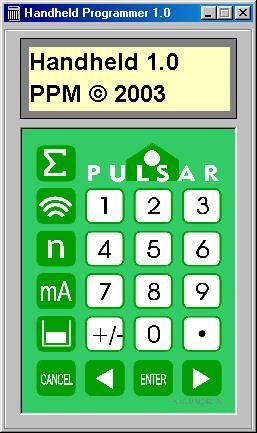
CONTENTS
Chapter 1: Start Here… ...........................................................................................................7
    About this Manual ...............................................................................................................7
    About the BlackBox .............................................................................................................8
    Functional Description .......................................................................................................9
    Product Specification ....................................................................................................... 10
    EU Declaration of Conformity ...................................................................................... 12
Chapter 2 Installation ........................................................................................................... 13
    Unpacking ............................................................................................................................ 13
    Power Supply Requirements......................................................................................... 13
    Location ................................................................................................................................ 13
    Dimensions .......................................................................................................................... 14
    Terminal Connection Detail .......................................................................................... 16
    Terminal Connection Detail .......................................................................................... 17
    ATEX ....................................................................................................................................... 17
    FM ........................................................................................................................................... 18
    Voltage Selector and Fuse Location .......................................................................... 19
    Preparation for Operation ............................................................................................. 20
    Maintenance ....................................................................................................................... 20
Chapter 3 How To Use Your BlackBox ........................................................................... 21
    On board integral Keypad ............................................................................................. 21
    PC Handheld Programmer ............................................................................................ 21
    Handheld Communicator (Optional) ......................................................................... 22
    Operating the Controls ................................................................................................... 23
    Hot Keys ................................................................................................................................ 24
    Menu Keys ........................................................................................................................... 25
    Numeric Keys ...................................................................................................................... 25
    Run Mode............................................................................................................................. 26
    LED’s ....................................................................................................................................... 26
    Program Mode ................................................................................................................... 26
    How to Access Program Mode .................................................................................... 27

4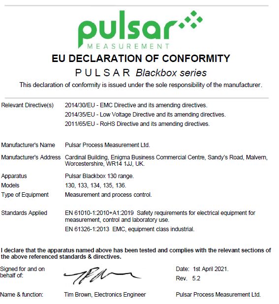
PULSAR MEASUREMENT

   Directly Editing Parameters ........................................................................................... 28
   Test Mode ............................................................................................................................ 29
   Using the RS232 Serial Interface ................................................................................. 30
   Parameter Defaults ........................................................................................................... 31
Chapter 4 Programming Guide ........................................................................................ 32
Chapter 5 Parameter Guide ............................................................................................... 38
   Menu System Diagrams ................................................................................................. 38
   Application Menu.............................................................................................................. 39
   Relays Menu ........................................................................................................................ 40
   Data Logs Menu ................................................................................................................ 41
   Volume Menu ..................................................................................................................... 42
   Display Menu ...................................................................................................................... 43
   mA Output Menu .............................................................................................................. 43
   Stability Menu .................................................................................................................... 44
   Echo Processing Menu .................................................................................................... 45
   System Menu ...................................................................................................................... 46
   Test Menu ............................................................................................................................ 47
   Application Parameters................................................................................................... 48
   Operation ............................................................................................................................. 48
   Dimensions .......................................................................................................................... 49
   Remote Alarm ..................................................................................................................... 51
   SMS Time.............................................................................................................................. 52
   Relay Parameters ............................................................................................................... 54
   Alarms .................................................................................................................................... 55
   Control ................................................................................................................................... 58
   Common Parameters ....................................................................................................... 60
   Data Logs ............................................................................................................................. 60
   Volume .................................................................................................................................. 61
   Breakpoints .......................................................................................................................... 67

                                                                                                                                               5
BLACKBOX 130 INSTRUCTION MANUAL
Tables ..................................................................................................................................... 68
Display Parameters ........................................................................................................... 69
Options .................................................................................................................................. 69
Failsafe ................................................................................................................................... 70
mA Output Parameters ................................................................................................... 71
Range ..................................................................................................................................... 71
Operation ............................................................................................................................. 71
Setpoint ................................................................................................................................. 72
Limits ...................................................................................................................................... 72
Trim ......................................................................................................................................... 73
Failsafe ................................................................................................................................... 73
Compensation Parameters ............................................................................................ 74
Stability Parameters ......................................................................................................... 75
Filters ...................................................................................................................................... 75
Echo Processing Parameters ......................................................................................... 76
System Parameters ........................................................................................................... 77
Passcode ............................................................................................................................... 77
System Information .......................................................................................................... 77
Date & Time ........................................................................................................................ 78
Daylight Saving Time ....................................................................................................... 78
Test Parameters ................................................................................................................. 82
Simulation ............................................................................................................................ 82
Hardware .............................................................................................................................. 83
Chapter 5 Troubleshooting ................................................................................................ 85
Chapter 6 Disposal ................................................................................................................ 86
6PULSAR MEASUREMENT
CHAPTER 1: START HERE…
Congratulations on your purchase of a Pulsar BlackBox 130 Level System.
This quality system has been developed over many years and represents the
latest in high technology ultrasonic level measurement and control.
It has been designed to give you years of trouble-free performance, and a
few minutes spent reading this operating manual will ensure that your
installation is as simple as possible
About this Manual
It is important that this manual is referred to for correct installation and
operation. There are various parts of the manual that offer additional help
or information as shown.
Tips
TIP: Loo k for t his icon throughout your Pulsar Measurement manual
to find helpful information and answers to frequently asked
questions .
Additional Information
Additional Information
At various parts of the manual, you will find sections
like this that explain specific things in more detail.
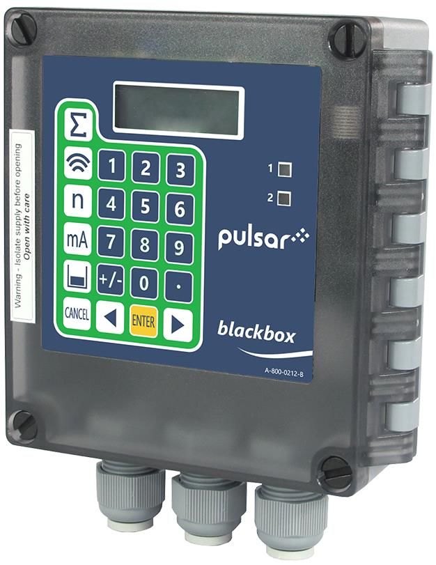
7BLACKBOX 130 INSTRUCTION MANUAL About the BlackBox The Pulsar BlackBox is a non-contact Level Control System. It has been designed to provide a new concept in low-cost maintenance-free fit and forget level measurement without any compromise on performance. The BlackBox is ideally suited to applications where level monitoring, reporting, control, or logging is required, with or without the need for a local display. The BlackBox level system is available in a variety of different versions offering a wide choice of output options. The BlackBox is very easy to use and may be calibrated quickly and simply via a laptop, using the software supplied with the unit, or alternatively by using the optional handheld calibrator, which connects to the unit via the RS232 interface, and provides an on-board LCD display. Certain models are also available with an optional LCD display and integral keypad fitted. All models of the BlackBox can be used with any of the extensive range of Pulsar transducers for distances up to 40m (131ft). The BlackBox is designed to provide you with highly reliable measurement in a robust and functional package that is easy to use and low in cost. 8
PULSAR MEASUREMENT

Functional Description
The BlackBox ultrasonic Level System sends a transmit pulse to the
transducer, which emits an ultrasonic pulse perpendicular to the transducer
face, and the returned echo is sent back to the BlackBox. The time taken to
receive the echo is measured and the distance from the transducer face to
the surface being monitored is calculated.
The BlackBox utilises the unique DATEM software (Digital Adaptive Tracking
of Echo Movement). This is a unique digital mapping technique developed
especially for Pulsar’s range of ultrasonic level and control systems. It gives
the system edge when identifying the “true target level” in the face of
competing echoes from pipes, pumps or other obstructions.
The BlackBox can measure from 0.125m (0.41 feet) to 40m (131 feet) from
the transducer to the surface being monitored, dependent on the
application and transducer used.
The BlackBox can measure level, space or distance and provide a
representative output. When fitted with the optional display and keyboard
it can also measure and provide an output representative of volume. There
are two user definable relays, with individual setpoints, which can be
programmed to activate alarms or control functions, a mA output that can
be used for remote indication purposes and a RS232 port, so that the
BlackBox can be programmed or monitored remotely by a PC or other
equipment.
The BlackBox can be programmed either by PC, via the RS 232 Serial
Interface, using the supplied software (standard) or by handheld calibrator
(optional) which is connected to the BlackBox via the RS 232 interface.
Those units fitted with the optional on-board display can be programmed
via the integral keyboard.
All the parameters are stored in non-volatile memory, so are retained in the
event of power interruption.

                                                                               9
BLACKBOX 130 INSTRUCTION MANUAL
Product Specification
PHYSICAL
Outside dimensions 143 x 150 x 63.5 mm (5.63 x 5.91 x 2.5”)
Weight Nominal 0.65 kg (1.4 lbs)
ABS base with Polycarbonate lid, flammability rating
Enclosure material/description
UL94HB
Underside fitted with 3 x M20, nylon cable glands
Cable entry detail
suitable for 6 – 12mm cable
Transducer cable extensions 2 – core screened. (2 conductor 20AWG screened)
1000 m (3,280 ft.). 500m (1,640 ft.) for dBR16 & dBR8,
Nominal separation
for greater distances consult Pulsar
ENVIRONMENTAL
IP Rating (Wall) IP66
Max. & min. temperature
-20 ºC to +50 ºC (-4ºF to 120ºF)
(electronics)
Flammable atmosphere Safe area: compatible with approved dB transducers (see
approval transducer spec' sheet)
CE Approval See EU Declaration of Conformity
PERFORMANCE
0.25% of the measured range or 6 mm (0.24”)
Accuracy
(whichever is greater)
0.1% of the measured range or 2 mm (0.08”) (whichever
Resolution
is greater). ±2mm for dBR16 & dBR8
Max. range Dependant on transducer (maximum 40m (131ft) dB40)
Dependent upon transducer (minimum 0.077m (0.252 ft)
Min. range
dBR16 & dBR8)
Rate response Fully adjustable
OUTPUTS
Isolated active output (passive output optional) of 4-20
Analogue output mA or 0-20 mA into 1K (user programmable and
adjustable) 0.1% resolution
Display 2 x 12 alpha numeric
Serial Port RS232 for programming and data extraction
Volt free contacts, number,
5 form "C" (SPDT) rated at 5A at 115V/240V AC
and rating
ECHO PROCESSING
Description DATEM (Digital Adaptive Tracking of Echo Movement)
10PULSAR MEASUREMENT
PROGRAMMING
On-board programming By integral keypad
Programming security Via passcode (user selectable and adjustable)
Programmed data integrity Via non-volatile RAM
PC Programming Via RS232 using supplied software
Remote programming via RS232 using optional hand-held calibrator
SUPPLY
115 VAC +5% / -10% 50/60 Hz,
230 VAC +5% / -10% 50/60 Hz,
Power Supply DC 10 - 28V
10W maximum power (typically 5W
50 mA at 230V AC (fitted as standard)
Fuses
100 mA at 115V AC (not supplied)
Pulsar Measurement operates a policy of constant development and
improvement and reserve the right to amend technical details, as necessary.
11BLACKBOX 130 INSTRUCTION MANUAL EU Declaration of Conformity 12
PULSAR MEASUREMENT

CHAPTER 2 INSTALLATION
Unpacking

 Important Notice
     All shipping cartons should be opened carefully. When using a box
     cutter, do not plunge the blade deeply into the box, as it could potentially
     cut or scratch equipment components. Carefully remove equipment from
     each carton, checking it against the packing list before discarding any
     packing material. If there is any shortage or obvious shipping damage to
     the equipment, report it immediately to Pulsar Measurement.

Power Supply Requirements
The BlackBox can operate from AC supply or from a DC battery. The AC is
115V +5%/-10% 50/60Hz or 230V +5%/-10% 50/60Hz, depending on the
position of the selector switch. The DC is 10-28V. In all cases the Blackbox
will typically consume 5W of power, with a maximum of 10W.
Location
All electronic products are susceptible to electrostatic shock, so follow proper
grounding procedures during installation.

The BlackBox must be mounted in a non-hazardous (safe) Area.

                                                                                    13
BLACKBOX 130 INSTRUCTION MANUAL
When choosing a location to mount the enclosure, bear in mind the
following:
• Easy access to the enclosure is maintained.
• The mounting surface is vibration-free.
• The ambient temperature is between -20ºC and 50ºC (-4ºF and
120ºF).
• There should be no high voltage cables or inverters close by.
Dimensions
The dimensions of the mounting holes are as shown below:
The BlackBox should be mounted by drilling four holes suitable for size 8
screws (length and type to suit your application) And fix all four screws by
removing the top cover to access the pre-moulded mounting holes which
are in the base of the enclosure under the lid retaining screws
14PULSAR MEASUREMENT
The full dimensions of the enclosure are as shown below.
13mm
130mm (5.12”) (0.51”) 63.5mm (2.5”)
150mm (5.91”)
3 off M20
Glands
Cable Entry
There are 3 x M20 cable glands, suitable for 6 – 12mm cables, fitted to the
base of the BlackBox enclosure.
Important Notice
All cable glands should be tightened to the manufacturer’s specifications.
The terminal compartment cover screws should be tightened to 0.5Nm
Care should be taken not to over tighten the screws.
15BLACKBOX 130 INSTRUCTION MANUAL Terminal Connection Detail The terminal strip is as detailed below. There is also a wiring diagram attached to the board directly underneath the terminal strip. 16
PULSAR MEASUREMENT

Terminal Connection Detail
Power
The BlackBox can operate from mains AC and automatically from a DC
power source or battery backup, in the event of power failure, or can be
operated permanently from DC or batteries.
Transducer
The transducer should be installed, and connected, in accordance with the
installation instructions contained in the Transducer User Guide.
The entire range of standard dB transducers are certified for use in
hazardous areas and different models, for each, are available for use in EEx
m (Zone 1) or EEx ia (Zone 0).
Wire the transducer to the BlackBox transducer terminals as detailed below:
                Red = Power (Terminal 19)
                White = Signal (Terminal 20)
                Black = 0 volts (Terminal 18)
                Green (screen) = SCR (Terminal 17)
When using 2 core screened extension cable, the Black and Green wires of
the transducer should be connected to the screen of the extension cable and
connected to the 0 volts’ terminal (Terminal 18).

ATEX
For EEx m (Zone 1) applications a transducer certified to Sira
02ATEX5104X is used, and must be supplied via a 4000A breaking fuse,
which is fitted as standard to the BlackBox level controller.
For EEx ia (Zone 0) a transducer certified to Sira 02ATEX2103X is used,
which must be connected to the BlackBox via an external Zener barrier.

                                                                               17
BLACKBOX 130 INSTRUCTION MANUAL FM For EEx m (Zone 1) applications a transducer certified to FM Class I Div 1 Group A, B, C & D, ClassII Div 1 Group E, F & G, Class III is used, and must be supplied via a 1500A breaking fuse, which is fitted as standard to the blackbox level controller. Restrictions do not use in the presence of these groups of Chemicals, Aliphatic Hydrocarbons, Ketones or Esters For EEx ia (I.S.) a transducer certified to FM Class I Div 1 Group A, B, C & D, ClassII Div 1 Group E, F & G is used, which must be connected to the blackbox via an external Zener barrier. See transducer label for certification details. Relay Outputs The two relays can be programmed to a variety of alarm & control functions. The relay contacts are all rated at 2A at 240V AC. All connections should be such that the short circuit capacity of the circuit to which they are connected, is limited by fuses rated so that they do not exceed the relay rating. Current Output This is an isolated active mA output of 4 - 20mA or 0 - 20mA, with an option of a passive mA output. The load should not exceed 1K. RS232 Serial Interface The serial interface is used to program the BlackBox either via a PC (standard) using the software supplied or alternatively using the handheld calibrator (optional). 18
PULSAR MEASUREMENT

Voltage Selector and Fuse Location
The voltage selector switch, and AC mains power fuse is located, on the
bottom board to the left and above of the power input terminals, as
previously illustrated in the Terminal Connections Detail drawing.

 Important Notice
 Before applying AC power (mains), make sure you have correctly selected the
 voltage selector switch which is located to the left and above of the mains
 supply input terminals, as illustrated in the Terminal Connections Detail drawing.
 Please note that all units are supplied set to 230 volts AC for safety reasons, with
 a 50mA fuse fitted as standard.
 Never operate the BlackBox with the cover removed.
 An external switch or circuit breaker should be installed near to the BlackBox to
 allow the supply to be removed during installation and maintenance. In addition,
 the relay contacts should also have a means of isolating them from the Blackbox.
 Interconnecting cables must be adequately insulated in accordance with local
 regulations. Strip back 30 mm of the outer insulation of the cable. Strip 5 mm of
 insulation from the end of each conductor. Twist all exposed strands of the
 conductor together. Insert the stripped conductor into the terminal block as far
 as it will go and tighten the terminal block screw. Ensure that all strands are
 firmly clamped in the terminal block and that there is no excess bare conductor
 showing, and no stray strands.

      Make sure you move the voltage sele ctor switch to t he correct
      position for your supply.

 Important Notice
 If the equipment is installed or used in a manner not specified in this manual,
 then the protection provided by the equipment may be impaired.

                                                                                        19
BLACKBOX 130 INSTRUCTION MANUAL
Preparation for Operation
Before switching on, check the following:
√ The BlackBox is mounted correctly and is in a ‘safe’ area.
√ The power supply is correctly installed.
√ The relays are connected correctly.
√ The voltage selector switch is in the correct position.
Maintenance
There are no user serviceable parts inside your Blackbox, except the mains
power fuse. If you experience any problems with the equipment, then please
contact Pulsar Process Measurement for advice.
To clean the equipment, wipe with a damp cloth. Do not use any solvents on
the enclosure or transducer.
Important Notice
The unique DATEM software comes into operation as soon as power is applied,
and is designed to monitor a moving level or target with the transducer in a
fixed position.
If, after any period of use, it should become necessary to move the transducer,
for any reason, from its original operating position, switch off the Blackbox,
before proceeding, to prevent any undesirable updates to the DATEM trace. If
after moving the transducer the reading is not as expected, please refer to
Chapter 6 Troubleshooting.
20PULSAR MEASUREMENT
CHAPTER 3 HOW TO USE YOUR BLACKBOX
To view or change parameter values one of the following methods must be
used:
On board integral Keypad
The onboard keypad can be used to program the BlackBox directly, or view
parameters. Simply enter the passcode 1997 and press enter, and you will
be taken into program mode where all parameters can viewed and changed
to suit your application.
PC Handheld Programmer
Your BlackBox 130 comes complete with the PC Handheld Programmer
software, contained on CD. Insert the CD into the CD drive of the PC
intended to be used to carry out the programming of the BlackBox and
install the software, following the on-screen instructions.
Once the software is installed connect the computer via its serial port to the
BlackBox RS232 serial interface RJ11 connector, located on the terminal
connector strip, inside the BlackBox enclosure. Double click the ‘Handheld
Programmer’ icon, installed on your desktop and the PC will automatically
connect to the Blackbox.
Once connected you will briefly see the message illustrated on the display
below which, after connecting successfully, will then change to display the
current measurement, dependent on mode and measurement unit's chosen.
When using the PC Handheld Programmer software, keypad input can be
achieved by using a ‘mouse’ or similar device to place the cursor over the
relevant key followed by a ‘left’ click, alternatively numeric detail can be
entered directly from the PC keyboard as can ‘ENTER’ and ‘CANCEL’ (Esc.
Key).
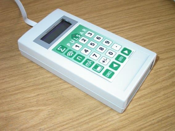
21BLACKBOX 130 INSTRUCTION MANUAL Communication Port Configuration If the PC Handheld Programmer fails to connect to the BlackBox unit you may need to change the communications port that is being used, to do this ‘right click’ on the PC Handheld Programmer keypad and a ‘pop up’ menu will appear allowing you to select the appropriate communications port. Handheld Communicator (Optional) The optional Handheld communicator can be used to programme any number of Blackbox units and works in a similar way to the PC Software. Connect the Handheld Communicator, with the cable supplied to the RS232 interface via the RJ11 connector located on the terminal connector, inside the BlackBox enclosure. Once connected you will briefly see a message, like that as seen when using the PC Software which, after connecting successfully, will then change to display the current measurement, dependent on mode and measurement unit's chosen. 22
PULSAR MEASUREMENT

Operating the Controls
Display
Whilst in the Run Mode it will display the current level or volume reading
and its units of measurement, along with the mA output and status
messages with regards to the communication status and Fail-Safe Mode.
When in Program mode, the display is used to read information on the
menu system, the parameter number and parameter details and values,
which can be entered.
During Test Mode the display is used to monitor the simulated level or
volume and mA output.
     1) Main Display, 12-digit alpha numeric display:
        Run Mode: current measurement displayed, dependent on
        measurement unit's chosen, and value of Hot Key function selected.
        Program Mode: displays parameter number and values entered for
        parameters.
        Test Mode: displays simulated level or volume.
                                              1

                               1234.56
                                  mm
                                               2
     2) Auxiliary Display, scrolling 12-digit alpha numeric display
        Run Mode: displays units, totaliser or status messages on
        communications, detail of Hot Key function selected.
        Program Mode: displays Menu and Sub Menu headings, parameter
        details and options.

                                                                             23
BLACKBOX 130 INSTRUCTION MANUAL
Hot Keys
There are five hot keys on the keypad, which can be used to quickly access
common parameters for viewing only, while in Run Mode. Pressing the hot
key once will display the first parameter, then repeated pressing will display
the others, then the BlackBox reverts to Run Mode. In program mode, they
have different functions, the functions are shown below.
HOT KEY RUN MODE PROGRAM MODE
∑ Not used with BlackBox 130. Not used with BlackBox 130.
Displays echo confidence, echo
strength, H.A.L.L., average
Not used with BlackBox 130.
noise, peak noise, or
temperature.
n Not used with BlackBox 130.
Reset parameter to default
setting
mA Instantaneous mA output Not used with BlackBox 130.
Dependant on application
displays Distance, Level, Space
Not used with BlackBox 130.
or Volume (optional) in units
of measurement.
Takes you to the last
Not used with BlackBox 130 parameter edited when you
first enter program mode.
Shows details of function type,
firmware revision and serial Enter decimal point.
number
24PULSAR MEASUREMENT
Menu Keys
The menu keys have the following functions:
Hot Key function
1) Arrow keys for moving left and right around the menu
system.
2) Used in test mode to simulate the level moving up and
down.
1) Used to confirm each action (for example select a menu
option) or when entering a parameter number or value
ENTER
2) Used to confirm questions asked by your BlackBox, such as
before restoring factory defaults
Used to navigate up a level in the menu system, and back to run
CANCEL mode.
Used to cancel a value entered in error.
Numeric Keys
These keys are used for entering numerical information during
programming.
1 2 3
4 5 6
7 8 9
+- 0 .
25BLACKBOX 130 INSTRUCTION MANUAL
There are two main operating modes for your BlackBox, Run Mode and
Program Mode. There is also a Test Mode, used for checking the set-up. All
modes are now described.
Run Mode
This mode is used once the BlackBox has been set up in program mode. It is
also the default mode that the unit reverts to when it resumes operation
after a power failure. When the Blackbox is switched on for the first time, it
will provide an output proportional to the distance from the transducer to
the target, in metres. All relays by default are switched off.
If either the PC Programming Software (standard) or the Handheld Calibrator
(optional), are connected to the BlackBox, via the RS232 interface, while the
Blackbox is in the RUN mode then the current measurement will be
displayed, dependent on mode and measurement unit's chosen. Models
fitted with the optional LCD display and integral keypad will also display the
current measurement, dependent on mode and measurement unit's chosen.
After programming is complete, any relays that are set will operate when the
measurement reaches the relevant setpoint.
LED’s
There are two LED’s that can be seen through the lid of the BlackBox
enclosure, which will indicate the operational status of the relays whilst in
RUN mode, as follows:
LED 1 LED 2 RUN MODE
Off Off Relays are in their OFF state
Constant On Off Relay 1 is in its ON state
Off Constant On Relay 2 is in its OFF state
Program Mode
This mode is used to set up the BlackBox or change information already set.
You must use either the on-board keypad (standard) or alternatively the unit
can be set up with a Handheld Calibrator (optional), which must be
connected to the BlackBox via the RS 232 Serial Interface.
Entering a value for each of the parameters that are relevant to your
application provides all the programming information.
26PULSAR MEASUREMENT
How to Access Program Mode
To enter program mode, you simply enter the passcode, via the keypad,
followed by the ENTER key. The default passcode is 1997, so you would
press the following:
1 9 9 7 ENTER
Important Notice
There is a time-out period of 15 minutes when in program mode, after
which time run mode will be resumed if you do not press any keys.
There are two means of editing parameters, directly or using the menu
system. Each is now described.
Using the Menu System
The menu system has been designed to make the changing of parameters
very simple. There are two levels of menu: Main Menu and Sub Menu.
On the display there is a line of text that shows the menu system. Pressing
the arrow keys scrolls the display between the top-level menu items, (as
shown below, starting at Application).
Application Relays Data Logs Volume Display Output
Echo
Compensation Stability System Test
Process
As you press the cursor keys to scroll left and right between these, you can
press ENTER at any time to select it and take you to the sub-menu. Each of
these options, along with their sub-menus is described in Chapter 5,
Parameter Guide. When you move down into the sub-menu, you can scroll
round using the arrow keys, press ENTER to go to the required section of
parameters.
27BLACKBOX 130 INSTRUCTION MANUAL
Once you have reached the relevant section, scroll through the parameters,
and enter the necessary information. To enter the information, use the
numeric keys and press ENTER and you will see the message “Saved!”. If you
press CANCEL, then no change will be made, and the message
“Unchanged!!” will be displayed.
When you have finished, press CANCEL to go back to the previous level.
When you have reached the top level, then the BlackBox will ask for
confirmation before allowing you to go back into run mode. This is done by
pressing ENTER at the display prompt.
Directly Editing Parameters
If you already know the number of the parameter, that you wish to look at or
edit, simply type the number in at any time while you are in the menu
system. Thus, if you are in either the menu or sub-menu level by pressing a
numeric key, you can enter the parameter number directly and jump straight
there. You cannot type a parameter number whilst at parameter level, only at
one of the two menu levels.
When you are at a parameter, the text line rotates automatically displaying
the parameter name, number, the applicable units, and the maximum and
minimum figure you can enter. The top line shows the value you are setting.
Once you have accessed a parameter, you can either just look at it, or
change it.
Once a parameter has been changed, press ENTER and you will see the
message “Saved!”. If you press CANCEL, then no change will be made, and
the message “Unchanged!!” will be displayed.
TIP: You can jump straight to the last parameter you edited, by pressing the +/-
key when you first enter program mode.
28PULSAR MEASUREMENT
Test Mode
Test mode is used to simulate the application and confirm that all
parameters and relay setpoints have been entered as expected. During
simulation, there is a choice of whether the relays will physically change
state (hard simulation) or not (soft simulation), the LED’s will always change
state to indicate that the relay setpoints have been activated, and the output
will change in accordance with the chosen mode of operation. If you wish to
test the logic of the system that the relays are connected to then select
hard simulation, but if you do not want to change the relay state, then
select a soft simulation.
There are two simulation modes, automatic and manual. Automatic
simulation will move the level up and down between empty level and
maximum span, whereas manual simulation will allow you to move the level
up and down using the arrow keys.
To enter simulation, first go to program mode. Then, using the menu
system, select menu item ‘Test’ then sub-menu item ‘Simulation’. Simply
change the value of the parameter P980 to one of the following:
1= Manual soft simulation
2= Automatic soft simulation
3= Manual hard simulation
4= Automatic hard simulation
To return to program mode, press CANCEL, and test mode will end.
When in manual simulation, by default test mode will move the level by
0.25m steps. Altering the increment (P981) will change this value.
In automatic mode, the rate at which the level moves up and down is set by
the increment (P981) in metres and the rate (P982) in minutes, which can
be changed to make the level move up and down faster. E.g., if increment
(P981) is set for 0.25m and rate (P982) is set to 1 min then the level will
increase or decrease at a rate of 0.25m/min. To make the simulated level
move slower, decrease the value in increment (P981) or increase the value
in rate (P982). To make the simulated level move faster, increase the value
in increment (P981) or decrease the value in rate (P982).
29BLACKBOX 130 INSTRUCTION MANUAL
LED’s
There are two LED’s that can be seen through the lid of the BlackBox
enclosure, which will indicate the operational status of the relays whilst in
RUN mode, as follows:
LED 1 LED 2 RUN MODE
Off Off Relays are in their OFF state
Constant On Off Relay 1 is in its ON state
Off Constant On Relay 2 is in its OFF state
Constant On Constant On Relay 1 and 2 in their ON state
Using the RS232 Serial Interface
The RS232 serial interface is used to program the Blackbox, and
communicate between the Blackbox and a PC using the optional BlackBox
PC and other associated Pulsar software packages, to obtain information
such as data logging and view echo traces upload, download and save
parameter files. In addition, it can also be used to control or obtain
information using a standard PC or other computer-based equipment. To do
so, the settings for control are as follows: baud rate 19200, 8 data bits, no
parity, 1 stop bits.
The device should be connected to the RS232 Interface via the RJ11
connector as shown in Chapter 2 Installation.
30PULSAR MEASUREMENT
Parameter Defaults
Factory Defaults
Important Notice
When first installing the BlackBox, or subsequently moving or using the
unit on a new application, before proceeding to program the unit for its
intended application it is recommended that you ensure that all
parameters are at their default values by completing a Factory Defaults
P930, as described in Chapter 5 Parameter Guide.
When you first switch the BlackBox on it will provide an output proportional
to the distance from the face of the transducer to the surface. All relays are
set OFF.
The date (P931) and time (P932) in the Blackbox were set at the factory, but
may need checking, and amending if, for example the application is in a time
zone other than GMT, see Chapter 5 Parameter Guide for full details.
TIP: In some applications, it is simplest to empty the vessel, take a reading from
the BlackBox and then setup the empty level to this figure.
Once you are satisfied with the installation, and the BlackBox is reading what
you would expect in terms of distance from the face of the transducer to the
material level, then you can proceed with programming, for the intended
application. It is sensible to program all the required parameters at the same
time. The system will be then set-up.
Note: that the span is automatically calculated from the empty level, so the
empty level should be entered first.
31BLACKBOX 130 INSTRUCTION MANUAL
CHAPTER 4 PROGRAMMING GUIDE
Example 1 Level Measurement
Empty Distance (P105), 3.5m
100%. Span (P106), 3.2m (output = 20mA)
High alarm on (P213), 2.38m
High alarm off (P214), 2.24m
Low alarm off (P224), 0.42m
Low alarm on (P223), 0.28m
0%, Empty level (output = 4mA)
In this example, the BlackBox and dB6 is being used to monitor a moving
level within a vessel and is required to provide a 4 to 20mA output
proportional to the level, over a range of 3.2m. In addition to when the level
rises to 2.5m, Relay ‘1’ is required to give a high alarm and rest when the
level falls to 2.4m. If the level should fall to 0.5m then Relay ‘2’ is to give a
low alarm and reset once the level rise to 0.6m.
32PULSAR MEASUREMENT
To program the BlackBox for this Example, proceed as follows.
Access the Program Mode, key in the passcode 1997 and press ENTER
Using the menu system access the parameters, as detailed below, and select
the relevant options and ENTER
PARAMETER SELECTED VALUE
P100 Mode 2 = Level
P101 Xducer 2 = dB6
P104 Measurement Units 1 = metres
P105 Empty Distance 3.5
P106 Span 3.2
P210 Relay 1 Type 1 = Alarm
P211 R1 Function 1 = Level
P212 R1 ID 2 = High
P213 R1 Setpoint 1 2.5
P214 R1 Setpoint 2 2.4
P220 Relay 2 Type 1 = Alarm
P221 R2 Function 1 = Level
P222 R2 ID 4 = Low
P223 R2 Setpoint 1 0.5
P224 R2 Setpoint 2 0.6
Programming is now complete, and the unit can be returned to the run
mode, press CANCEL until Run Mode? Is displayed on the display press
ENTER, and the BlackBox will return to the Run Mode.
Important Notice
The 4 to 20mA output will be automatically set to the value of P106 Span,
with 4mA being representative of 0% of Span (zero level) and 20mA 100%
of Span (Full level).
33BLACKBOX 130 INSTRUCTION MANUAL
Example 2 Alternating Control (Pump Down)
A sump is typically used to temporarily hold water or effluent, and when the
level reaches a specific point, the sump is pumped down, with the fluid
being transferred to another process.
Empty Distance (P105), 5.0m
100%. Span (P106), 4.7m (output = 20mA)
Pump 2 on (P223), 1.4m
Pump 1 on (P213), 1.0m
Pump 1+2 off (P214, 224), 0.5m
0%, Empty level (output = 4mA)
In this example a BlackBox with dB6 is being used to control pumps on a
pump down application, there are two pumps, and the duty pump is to be
alternated between the pumps.
This will operate as follows. During normal operation, pump 1 will come on
at 1.0 m, and pump down to 0.5 m. The setpoints are then shifted to pump
2, which will come on first next time.
During peak periods, when pump 1 cannot cope, pump 1 will come on at
1.0m, pump 2 will come on at 1.4 m, and pump down to 0.5 m. The
setpoints are then shifted to pump 2, which will come on first next time.
The 4 to 20mA output will be representative of level.
34PULSAR MEASUREMENT
To program the BlackBox for this Example, proceed as follows.
Access the Program Mode, key in the passcode 1997 and press ENTER
Using the menu system access the parameters, as detailed below, and select
the relevant options and ENTER
PARAMETER SELECTED VALUE
P100 Mode 2 = Level
P101 Xducer 2 = dB6
P104 Measurement Units 1 = metres
P105 Empty Distance 5.0
P106 Span 4.7
P210 Relay 1 Type 2 = Control
P211 R1 Function 1 = General
P212 R1 ID 2 = Alternate
P213 R1 Setpoint 1 1.0
P214 R1 Setpoint 2 0.5
P220 Relay 2 Type 2 = Control
P221 R2 Function 1 = General
P222 R2 ID 2 = Alternate
P223 R2 Setpoint 1 1.4
P224 R2 Setpoint 2 0.5
Programming is now complete, and the unit can be returned to the run
mode, press CANCEL until Run Mode? Is displayed on the display press
ENTER, and the BlackBox will return to the Run Mode.
Important Notice
The 4 to 20mA output will be automatically set to the value of P106 Span,
with 4mA being representative of 0% of Span (zero level) and 20mA 100%
of Span (Full level).
35BLACKBOX 130 INSTRUCTION MANUAL
Example 3 Volume
A cylindrical tank with a diameter of 2m and a flat base that is typically used
to temporarily hold liquid, and you wish to know the volume of liquid. You
also require a high and low alarm.
Empty Distance (P105), 4.5m
100%. Span (P106), 3.8m (output = 20mA)
High alarm on (P213), 3.4m
High alarm off (P214), 3.2m
Low alarm off (P224), 0.5m
Low alarm on (P223), 0.3m
0%, Empty level (output = 4mA)
In this example, if the level rises to 3.4 m, then the high-level alarm (relay 1)
will come on until the level drops to 3.2 m. If the level falls to 0.3m, then the
low-level alarm (relay 2) will come on until the level rises to 0.5 m.
The display will show the volume of fluid in the tank and the mA output will
be representative of Volume where 4mA = empty (0%) and 20mA = Max
Volume (100%).
36PULSAR MEASUREMENT
To program the BlackBox for this Example, proceed as follows.
Access the Program Mode, key in the passcode 1997 and press ENTER
Using the menu system access the parameters, as detailed below, and select
the relevant options and ENTER
PARAMETER SELECTED VALUE
P100 Mode 5 = Volume
P101 Xducer 2 = dB6
P104 Measurement Units 1 = metres
P105 Empty Distance 4.5
P106 Span 3.8
P210 Relay 1 Type 1 = Alarm
P211 R1 Function 1 = Level
P212 R1 ID 2 = High
P213 R1 Setpoint 1 3.4
P214 R1 Setpoint 2 3.2
P220 Relay 2 Type 1 = Alarm
P221 R2 Function 1 = Level
P222 R2 ID 4 = Low
P223 R2 Setpoint 1 0.3
P224 R2 Setpoint 2 0.5
P600 Vessel Shape 0 = Cyl. Flat Base
P601 – P603 Vessel
Enter dimensions as required
Dimensions
Shows the volume as calculated by
P604 Calc. Volume
the BlackBox
P605 Volume Units Select as required
Enter value of any correction factor
P606 Correction Factor
e.g., specific gravity of material
Displays the Max Volume as
P607 Max Volume
calculated by the BlackBox
Programming is now complete, and the unit can be returned to the run
mode, press CANCEL until Run Mode? Is displayed on the display press
ENTER, and the BlackBox will return to the Run Mode.
37BLACKBOX 130 INSTRUCTION MANUAL
CHAPTER 5 PARAMETER GUIDE
This chapter describes all the parameters in your BlackBox, in the order they
appear in the menu system.
Menu System Diagrams
Shown below is a set of charts to show you how all the various parts can be
found using the menu system.
Top Level Menu
Application Relays Data Logs Volume Display Output
Echo
Compensation Stability System Test
Process
38PULSAR MEASUREMENT
Application Menu
Operation Distances Remote Alarm SMS Time
P100 P104 P985 Tel. No 1 P995 Interval
Mode Measurement
Units
P986 Tel. No 2 P996 SMS Start
P101
P105
Transducer
Empty Level
P987 Tel. No 3 P997 SMS Stop
P102 P106
Material Span
P988 Call Type P998 SMS Days
P107
Near Blanking
P108
Far Blanking
39BLACKBOX 130 INSTRUCTION MANUAL
Relays Menu
Relay 1 Relay 2
P210 P220
R1 Type R2 Type
P211 P221
R1 Function R2 Function
P212 P222
R1 I/D R2 I/D
P213 P223
R1 Setpoint R2 Setpoint
1 1
P214 P224
R1 Setpoint R2 Setpoint
2 2
P217 P227
R1 Closures R2 Closures
P218 P228
R1 Failsafe R2 Failsafe
40PULSAR MEASUREMENT
Data Logs Menu
Temperature
P580
Min Temp
P581
Min Temp Date
P582
Min Temp Time
P583
Max Temp
P584
Max Temp Date
P585
Max Temp Time
P586
Current Temperature
41BLACKBOX 130 INSTRUCTION MANUAL
Volume Menu
Conversion Breakpoints Tables
P600 P610 P696
Vessel Shape Level Bkpt. 1 Reset
Bkpts.
P601 P611
As Required Vol. Bkpt. 1
Vol. Dimension 1
P612, 614, 616, 618,
P602 620, 622, 624, 626,
As Required 628, 630, 632, 634,
Vol. Dimension 2 636, 638, 640, 642,
644, 646, 648, 650,
P603 652, 654, 656, 658,
As Required 660, 662, 664, 666,
Vol. Dimension 3 668, 670
Level Bkpts. 2 to 31
P604
Calculated P613, 615, 617, 619,
Volume 621, 623, 625, 627,
629, 631, 633, 635,
P605 637, 639, 641, 643,
Volume Units 645, 647, 649, 651,
653, 655, 657, 659,
P606 661, 663, 665, 667,
Correct. Factor 669, 671
Vol. Bkpts. 2 to 31
P607
Max. Volume P672
Level Bkpt. 32
P673
Vol. Bkpt. 32
42PULSAR MEASUREMENT
Display Menu
Options Fail Safe
P800 P808
Display Units Fail Mode
P801 P809
Decimal Places Fail Time
P802
Display Offset
P804
Display Conversion
mA Output Menu
Range Operation Setpoints Limits Trim Fail Safe
P830 P831 P834 P836 P838 P840
mA mA Mode Low Value Low Limit Low Trim Fail Mode
Range
P835 P837 P839
High High High Trim
Value Limit
43BLACKBOX 130 INSTRUCTION MANUAL
Stability Menu
Damping Filters
P870 P881
Fill Damping Fixed Distance
P871 P882
Empty Damping Process Filter
44PULSAR MEASUREMENT
Echo Processing Menu
Transducer (Xdr.)
Status
P900
Xdr. 1 Status
P901
Echo Confidence
P902
Echo Strength
P903
Average Noise
P904
Peak Noise
P905
Sensitivity
P906
Side Clearance
45BLACKBOX 130 INSTRUCTION MANUAL
System Menu
Date
System Daylight
Passcode &
Info Saving
Time
P921 P926 P931 P970
Enable Software Date DST Enable
Code Revision
P971
P932
P927 DST
P922 Time
Hardware Difference
Passcode
Revision
P933 P972
P928 Date DST Start
Serial Format Time
Number
P973
Start Day
P929
Site
Ident. P974
Start Week
P930
P975
Factory
Start
Default
Month
P976
DST End
Time
P977
End Day
P978
End Week
P979
End Month
46PULSAR MEASUREMENT
Test Menu
Simulation Hardware
P980 P990
Simulate Self-Test
P981 P991
Increment Hard Test
P982 P992
Rate Out Test
P993
Relay Test
P994
Transducer Test
47BLACKBOX 130 INSTRUCTION MANUAL
Parameter Listing
This section describes all the parameters. Any parameter can be reset to its
default, by pressing the hot key, whilst in program mode.
Application Parameters
Operation
P100 Mode of Operation
This parameter sets the mode of operation, when in run mode, and can be
set to one of the following:
OPTION DESCRIPTION
Display and Output relative to the distance from the
1 = Distance (Default)
transducer to the surface.
2 = Level Display and Output relative to how full the vessel is.
Display and Output relative to how empty a vessel
3 = Space
is.
Display and Output relative to volume of material in
5 = Volume
the vessel.
P101 Transducer
This parameter should be set to the transducer being used with the unit, and
can be set to one of the following:
OPTION DESCRIPTION
1 = dB3 No Effect
2 = dB6 (Default) Transducer is a dB6. Range 0.3 to 6m
3= dB10 Transducer is a dB10. Range 0.3 to 10m
4= dB15 Transducer is a dB15. Range 0.5 to 15m
5= dB25 Transducer is a dB25. Range 0.6 to 25m
6 = dB40 Transducer is a dB40. Range 1.2 to 40m
7 = dBS6 Transducer is a dBS6. Range 0.2 to 6m
*9 = dBR16 Transducer is a mmWave radar. Range 0.077 to 16 m
*10 = dBR8 Transducer is a mmWave radar. Range 0.077 to 8 m
*Please consult Pulsar for versions of compatible firmware that the mmWAVE is
available in.
48PULSAR MEASUREMENT
P102 Material
This parameter should be set to the type of material being monitored
OPTION DESCRIPTION
1 = Liquid Use for liquids and flat solids
2 = Solid Solid material that is heaped at an angle
3 = Closed Tank Use for applications within a closed vessel or where
a secondary echo response may become focused to
create a larger echo than the first.
Dimensions
P104 Measurement Units
This parameter sets the units you want to use for programming and display
OPTION DESCRIPTION
1 = metres (Default) All units of measure are METRES
2 = cm All units of measure are CENTIMETRES
3 = mm All units of measure are MILLIMETRES
4 = feet All units of measure are FEET
5 = inches All units of measure are INCHES
P105 Empty Level
This parameter is to be set to the maximum distance from the face of the
transducer to the empty point, in P104 Measurement Units.
Important Notice
When changing the Empty Distance (P105) you can also recalculate the
values for the Span so that it equals the empty distance (P105) minus
Near Blanking (P107) and the Relay Setpoints, so that they remain at the
same percentage values of the empty distance as they were before you
changed the empty distance (P105). You will be asked the question
“Recalculate Span?” if you choose yes (enter 1), then the span will be
recalculated. Any other answer will leave the span at its original value.
You will then be asked if you want to “Recalculate Setpoints?”, if you
choose Yes (enter 1), then all Relay Setpoints will be recalculated as a
percentage of the new empty distance. Any other answer will leave the
setpoints at their original values.
49BLACKBOX 130 INSTRUCTION MANUAL
P106 Span
This parameter should be set to the maximum distance from the Empty
Level (P105) to the maximum material level. It is automatically set to be
equal to the Empty Level (P105) less the Near Blanking distance (P107)
when you set the empty level.
P107 Near Blanking
This parameter is the distance from the face of the transducer that is not
measurable, and is pre-set to the minimum value dependant on the Xducer
(P101) selected. It should not be set to less than this figure, but can be
increased, typical to ignore close in obstructions.
OPTION DESCRIPTION
P101 = dB3 Default Blanking Distance = 0.125m
P101 = dB6 Default Blanking Distance = 0.300m
P101 = dB10 Default Blanking Distance = 0.300m
P101 = dB15 Default Blanking Distance = 0.500m
P101 = dB25 Default Blanking Distance = 0.600m
P101 = dB40 Default Blanking Distance = 1.200m
P101 = dBS6 Default Blanking Distance = 0.200m
P101 = dBR16 Default Blanking Distance = *0.077m
P101 = dBR8 Default Blanking Distance = *0.077m
*The signal emanates from the curved face of the Radar, but for the purposes
of measurement it is taken from the drip shield.
P108 Far Blanking Distance
This is the distance (as a percentage of empty level P105) beyond the
empty point that the unit will be able to measure, and by default is pre-set
to 20% of the empty level.
If the surface being monitored can extend beyond the Empty Level (P105)
then the far blanking distance can be increased to a maximum of 100% of
empty level.
This parameter is always entered as a % of empty level.
50You can also read