Detecting Traffic Incidents Using Persistence Diagrams - MDPI
←
→
Page content transcription
If your browser does not render page correctly, please read the page content below
algorithms
Article
Detecting Traffic Incidents Using Persistence Diagrams
Eric S. Weber * , Steven N. Harding and Lee Przybylski
 Department of Mathematics, Iowa State University, Ames, IA 50011, USA; sharding@iastate.edu (S.N.H.);
 leep@iastate.edu (L.P.)
 * Correspondence: esweber@iastate.edu

 Received: 30 June 2020; Accepted: 29 August 2020; Published: 5 September 2020

 Abstract: We introduce a novel methodology for anomaly detection in time-series data. The method
 uses persistence diagrams and bottleneck distances to identify anomalies. Specifically, we generate
 multiple predictors by randomly bagging the data (reference bags), then for each data point replacing
 the data point for a randomly chosen point in each bag (modified bags). The predictors then are
 the set of bottleneck distances for the reference/modified bag pairs. We prove the stability of the
 predictors as the number of bags increases. We apply our methodology to traffic data and measure
 the performance for identifying known incidents.

 Keywords: persistence diagram; bottleneck distance; anomaly detection; bagging; incident detection

1. Introduction
     Traffic incidents are severely detrimental to society in terms of financial costs which are estimated
in the U.S. by the National Highway Traffic Safety Administration [1]. Consequently, an important
focus of data analysis concerns detecting incidents from traffic data for the management of response to
accidents which can have significant benefits for society [2]. The type of data we consider is a time
series of volumetric traffic counts. We propose a novel methodology for analyzing this data for the
purpose of identifying traffic incidents.. Our approach is to view the identification of incidents as
a problem of anomaly detection within the time-series data. Our method uses tools from statistical
analysis–bootstrap aggregation or bagging–and from topological data analysis (TDA)–persistence
diagrams–to form an ensemble of predictors to determine whether data points are normal or anomalous.
To each data point and random bag, we associate two persistence diagrams, one reference and one
modified. The predictors then consist of a score–the bottleneck distance between the diagrams–and for
each data point, the set of scores are aggregated into several summary statistics. We then identify data
points as being incidents or anomalies by percentile scores of the summary statistics.
     Our algorithm using randomized bagging of the data and resultant persistence diagrams as a
feature extractor for anomaly detection can be viewed as a semi-supervised learning algorithm. Indeed,
our method trains the summary statistics on a small amount of labeled data. Moreover, our algorithm
can be applied to any vectorized data and, thus, can be adapted for many other data analytic problems.

1.1. Description of the Data and Challenge Problem
     The problem we address is to identify incidents in a data set of volumetric traffic counts obtained
from multiple inductive loop road sensors, [3], supplied by the California Department of Transportation.
The counts were aggregated over 5 min intervals, and we had access to one full calendar year of traffic
counts for each sensor. See Table 1 for a sample from the data. We apply our method to this data set in
Section 4.

Algorithms 2020, 13, 222; doi:10.3390/a13090222                            www.mdpi.com/journal/algorithms
Algorithms 2020, 13, 222 2 of 19
Table 1. A sample of the traffic counts from Phase 1-Train.
S312425 S312520 S312694 S312942 S314147 Timestamp
45 82 62 102 50 1/1/2017 0:00
39 66 60 109 54 1/1/2017 0:05
35 92 87 99 80 1/1/2017 0:10
67 136 120 111 136 1/1/2017 0:15
104 160 148 103 122 1/1/2017 0:20
100 141 161 137 159 1/1/2017 0:25
110 176 173 150 149 1/1/2017 0:30
76 159 157 161 175 1/1/2017 0:35
105 166 166 146 188 1/1/2017 0:40
93 176 143 172 157 1/1/2017 0:45
127 168 152 194 133 1/1/2017 0:50
137 171 174 187 169 1/1/2017 0:55
Our task to identify incidents was part of an anomaly detection problem hosted by the Joint
Algorithms for Threat Detection (ATD) and Algorithms for Modern Power Systems (AMPS) Annual
Workshop; the challenge problem that we specifically addressed was curated for the ATD program [4].
The challenge problem consisted of two phases: in Phase 1, we were asked to detect incidents within
data provided by 10 road sensors that were spatially located to be independent from one another
(we were not informed of the locations); in Phase 2, we were asked to repeat Phase 1 provided
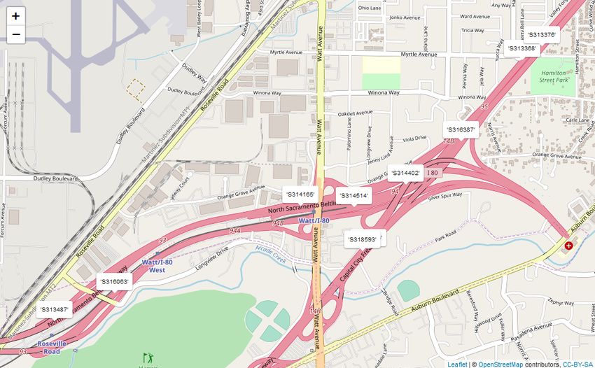
additional information on the location of the sensors–see Figure 1. For each phase, we were supplied
with a training data set and a testing data set with labeled incidents that were hand-selected by the
ATD program coordinators. The training data set for Phase 1 contained 9 labeled incidents, and the
training data set for Phase 2 contained 10 labeled incidents. There were numerous unlabeled incidents
in the training data sets.
Figure 1. A map of sensor locations from Phase 2-Train.
The timeline of the challenge problem was as follows:
1. Phase 1 training data posted: 15 January 2019
2. Phase 1 testing data posted: 22 March 2019
3. Phase 1 solution deadline: 2 May 2019Algorithms 2020, 13, 222 3 of 19
4. Phase 2 training data posted: 24 May 2019
5. Phase 2 testing data posted: 15 July 2019
6. Phase 2 solution deadline: 27 September 2019
Supplementary materials in the form of data sets and code are available at the following repository:
https://bitbucket.org/esweber/randomized-persistence-landscapes/src/master/.
Data sets for the challenge problem were originally released as files in MATLAB. We have
converted the data to comma-separated values files and all experiments discussed in the paper can be
reproduced by executing our code in R-Studio. Our solutions were submitted as a binary output for
each 5 min interval with 1 indicating an incident and 0 otherwise. Three evaluation metrics were then
used to evaluate the performance of our algorithm: precision, recall, and an F-score.
1.2. Survey of Literature
Detecting incidents in traffic data is important for the safety and welfare of society [2].
Significant efforts have been made to automate incident detection [5–8]. Traditional automatic incident
detection data sources include radar sensors [9], video cameras [10], probes [11]. Loop detectors are
also a very common source of traffic data [3,12], which is the source of the traffic data analyzed in
our method.
Detecting incidents in traffic data can be formulated as an anomaly detection problem.
Approaches in this formulation include: dynamic clustering [13] or Support Vector Machines [14]
to detect anomalous trajectories, autoencoders to learn regularity of video sequences [15],
motion reconstruction [16], and convolutional neural networks to predict congestion in traffic
networks [17]. In this paper, we also view incident detection as an anomaly detection problem,
with our approach using TDA to identify outliers. For an overview of anomaly detection, see [18].
Topological data analysis has been used previously in the context of traffic data: [19] uses TDA as a
model for tracking vehicles and [20] uses TDA to understand individual travel behaviors. TDA has also
been used previously for anomaly detection in [21,22]. TDA provides a framework for studying the
“shape” of data in geometric and topological terms rather than a solely statistical framework [23–25].
TDA has been an extremely successful tool in applied algebraic topology across a multitude
of applications, including analysis of neural networks [26,27], data dimension reduction
techniques [28,29], anomaly detection [21,22] biological studies [30], viral evolution [31], the study of
blood flow through brain arteries [32], and tracking vehicles [19]. TDA has been applied previously
to study time-series data in a variety of settings [33,34]. Existing applications include to financial
data [35–37], medical signal (EEG) analysis [38,39] and general techniques including sliding-window
methods [40–43]. Most of these methods rely on a Takens-style embedding to transform time-series
data into point-cloud data [44,45]. In contrast, our method does not require such an embedding.
Our algorithm is motivated by the intuition that if we take a data set of vectors that represent
typical behavior and one of the vectors were replaced with an anomalous observation, the topology
of the data set would be significantly altered. This intuition is supported by randomized persistence
diagrams [46,47]. For example, [48] finds that samples from a manifold corrupted by noise with
a Gaussian distribution will not in general significantly deviate from the persistence diagram of
the underlying manifold, but other distributions could. Further results in [49] emphasize this by
showing that extending the stability results for noise with a Gaussian distribution in [48] to other noise
distributions should not “be expected”.
1.3. Main Contributions
Our main contributions in this paper are two-fold. First, we introduce a novel machine learning
algorithm that uses TDA for detecting anomalies in time-series data. This is done by establishing
a baseline of typical data distribution to serve as a reference through the method of bagging,
and deviations from the reference for various data points are measured using the bottleneck distanceAlgorithms 2020, 13, 222 4 of 19
from TDA. This procedure is repeated multiple times to reduce the variation that naturally arises from
random sampling. The algorithm requires selection of several hyperparameters. Second, we address
the problem of identifying incidents in traffic data that consists only of traffic counts. Our data set does
not include any functional data, such as velocity, nor does it include video feed which are the most
common data sources used in traffic incident detection problems.
1.4. Outline
The rest of the paper is organized as follows. In Section 2 we present the necessary background for
understanding persistence diagrams, the fundamental tool from TDA that our algorithm implements.
In Section 3 we present the algorithm. In Section 4 we present the results of our algorithm when
applied to the traffic data set from the ATD challenge problem.
2. Topological Data Analysis (TDA)
Here, we provide the necessary background for understanding the TDA that our algorithm
implements. For more details on the subject, see [50,51]. The appeal of TDA is that it offers techniques
from topology to ascertain the "shape" of high-dimensional data sets that is not accessible by other
methods. In particular, persistent homology is ubiquitous in TDA for measuring certain topological
features of a space (e.g., connectivity, holes, voids). These features are often summarized using Betti
numbers or a persistence diagram [23]. Our focus will be on the latter and the bottleneck distance
which serves as a metric on a set of those diagrams.
2.1. Persistence Diagrams
Persistence diagrams are computed based on the notion of a simplicial complex. It is natural to
think of a simplicial complex in a Euclidean space, but a more abstract definition adequately serves
our purposes.
Definition 1 (Abstract Simplicial Complex). A finite collection of sets A is called an abstract simplicial
complex if A is closed under subset inclusion, i.e., if β ∈ A whenever α ∈ A and β ⊂ α. Furthermore, we call
α ∈ A a combinatorial p-simplex if |α| = p + 1.
In our consideration, each simplex is a subset of data points. There are several useful methods by
which to construct simplicial complexes from data. We have chosen the Vietoris–Rips (VR) complex
for its computational convenience.
Definition 2 (Vietoris–Rips Complex). Let Y be a finite subset of data points contained in some metric space
X. For every r ≥ 0, the Vietoris–Rips Complex of Y at scale r is defined as
VRr (Y ) := {α ⊂ Y : diam(α) ≤ 2r }.
We note that the VR complex is ascending in the sense that VRr0 (Y ) ⊂ VRr (Y ) for r0 ≤ r.
Thus, as the radius r increases, we produce a filtration of simplicial complexes on top of the data
points in Y. This filtration yields a persistent homology that quantifies the apparent topological
features for different dimensions. 0-, 1-, and 2-dimensional features refer to connected components,
holes, and voids, respectively. Higher-dimensional features would be the analogues of these features.
The persistence diagram quantifies the importance of these features in terms of their persistence
over various radii. Persistence gives us a sequence of homology groups for each dimension of the
ambient metric space containing the data. By identifying the radii in the sequence when the topological
features appear and disappear we obtain a collection of birth and death times for each feature of
each dimension.Algorithms 2020, 13, 222 5 of 19
The birth-death pairs as a multiset in R2 make up the persistence diagram corresponding to
Y. The persistence diagrams in our algorithm only contain information on connected components,
the zero-dimensional features. We were unable to find a meaningful use for persistence diagrams
computed using higher-dimensional features.
2.2. Bottleneck Distance
We use the bottleneck distance to make comparisons between two persistence diagrams.
The bottleneck distance can be thought of more generally as a pseudometric on multisets P and
Q that quantifies the cost of mapping P to Q. To be precise, suppose P and Q are plain multisets
2
of points in the extended plane R . We say M ⊂ P × Q is a partial matching between P and Q if it
satisfies the following:
• For each q ∈ Q, there exists at most one p ∈ P such that ( p, q) ∈ M.
• For each p ∈ P there exists at most one q ∈ Q such that ( p, q) ∈ M.
We say that s ∈ P ∪ Q is unmatched if there does not exist p ∈ P with ( p, s) ∈ M or q ∈ Q such
that (s, q) ∈ M. Let ∆ := {( x, x ) : x ∈ R}. Please note that if s = (s x , sy ), then if z ∈ ∆ satisfies
z = arg min{ks − x k2 : x ∈ ∆}, then
|s x − sy |
ks − zk∞ = .
2
We define the cost function for each matching M to be
!
|s x − sy |
c( M ) = max sup k p − qk∞ , sup .
( p,q)∈ M s∈ P∪ Q, unmatched 2
Definition 3 (Bottleneck Distance). Let M( P, Q) be the set of all partial matchings between P and Q.
We define the bottleneck distance between P and Q as
W ( P, Q) := inf c ( M ).
M ∈M( P,Q)
Remark 1. We refer to the bottleneck distance as a pseudometric because there
√ are multisets P and Q such that
P 6= Q yet W ( P, Q) = 0. Take for example P = Q2 \∆ and Q = (Q + 2)2 \∆. Although c( M) > 0 for
every M ∈ M( P, Q), we find W ( P, Q) = 0 by taking an infimum over M( P, Q). It has been shown that in
2
the case where P and Q are finite multisets in R \∆ then W ( P, Q) = 0 implies P = Q, [52].
3. Description of the Algorithm
Our algorithm is motivated by the intuition that if we take a data set of vectors that represent
typical behavior and one of the vectors were replaced with an anomalous observation, the topology
of the data set would be significantly altered. The topology of the set is understood by computing
persistence diagrams of randomly chosen subsets β ⊂ {xi }im=1 . When we modify a bag β by randomly
replacing one of its vectors with x j we denote the resulting modified bag by β( j) . Figure 2 depicts the
data points in the reference and modified bags. We then let D and D ( j) denote the persistence diagrams
for vectors in β and β( j) , respectively. Figure 3 depicts the persistence diagrams for the reference and
modified bags for a specfic data point.Algorithms 2020, 13, 222 6 of 19
Figure 2. The left side represents one of the reference bags, while the right side represents the
corresponding modified bag for week 6.
Figure 3. A plot of the persistence diagram for 20th reference diagram (left) and the modified
persistence diagram (right) when week 6 replaces one of the randomly chosen observations in the
7th reference bag. This corresponds to the traffic behavior at sensor S314402 on Monday, 6 February
2017 from 7:55–8:55 AM.
The bottleneck distance quantifies how much the topology of a set has changed. We say
there is evidence that x j is anomalous if W ( D, D ( j) ) is relatively large compared to the values in
{W ( D, D (i) )}im=1 . There are some undesirable cases that may occur due to the random sampling used
to form β. It may be that the observations contained in β do not adequately represent the entire data
set, or if the reference bag contains an anomaly, we might replace an anomaly with a non-anomalous
vector when forming the modified bag. To mitigate issues such as these, the algorithm uses multiple
bags of the same size. We select hyperparameters S, N ∈ N and repeat N times the process of randomly
choosing S vectors to form β. This creates a collection of reference bags { β k }kN=1 . For each of the
( j)
N bags, we form m distinct modified bags { β k }m j=1 by randomly choosing y ∈ β k and replacing it
with x j . We calculate the summary statistics mean, median, and standard deviation for the bottleneck
distances, and choose a function f : R3 → {0, 1} that identifies anomalies from the summary statistics.
The entire algorithm is presented in Algorithm 1.Algorithms 2020, 13, 222 7 of 19
Algorithm 1: Anomaly Detection using Persistence Diagrams of Random Subsamples
Input: D := {x j }m n
j=1 ⊂ R , S, N, f
1 for k ∈ {1, ..., N } do
2 Randomly sample S vectors to form data set β k
3 Compute the persistence diagram Dk for β k
4 for j ∈ {1, ..., m} do
( j)
5 Construct modified bag β k by replacing a randomly selected vector y j ∈ β k with x j
( j) ( j)
6 Compute the persistence diagram Dk for β k
( j)
7 Compute and store d j,k = W ( Dk , Dk )
8 end
9 end
10 for j ∈ {1, ..., m} do
11 Compute the mean d j , median h j , and standard deviation s j of {d j,k }kN=1
12 Identify x j as an anomaly if f (d j , h j , s j ) = 1
13 end
The summary statistics of the bottleneck distances {d j,k }kN=1 can be used in various ways
depending on the application. In our application to traffic data, we set thresholds for each summary
statistic based on training data. Thus, we set thresholds τ1 , τ2 , τ3 for the three summary statistics,
and we defined f (d j , h j , s j ) = 1 if and only if d j ≥ τ1 , h j ≥ τ2 , and s j ≥ τ3 .
In addition to those previously mentioned, we may also encounter the issue when the modified
bag β(k) is formed by replacing the same vector xk . This would make an anomaly look much less
anomalous based on our bottleneck distance measurement. Fortunately, if N is chosen to be sufficiently
large, then the effect can be very small since the summary statistics converge in probability. Let us
formalize the probability distribution here. The sample space consists of ordered pairs
Ω = {( β, y) : β ⊂ D, | β| = S, y ∈ β}.
We place the uniform distribution on Ω and denote this by P .
Theorem 1. Let d j , s j , and h j be denote the mean, standard deviation, and median respectively of bottleneck
distance associated with x j as computed in Algorithm 1. Then there exist µ j , σj , η j+ , and η j− such that
P P
d j −→ µ j , s j −→ σj
as N −→ ∞, and for all ε > 0,
lim P[h j ∈ (η j− − ε, η j+ + ε)] = 1.
N →∞
Proof. Define the random variable d j on Ω by
d j ( β, y) = W ( β, β \ {y} ∪ {x j }).
d
We have that d j,1 , d j,2 , ..., d j,N = d j are i.i.d. random variables. Since |Ω| < ∞ and there are no
infinite points in D, d j is bounded. The three limits are consequences of the Weak Law of Large
Numbers, which requires a sequence of i.i.d. random variables with finite expectation. In particular,
let µ j := E[d j ] < ∞ and σj2 = Var[d j ] < ∞. Since the {d j,k }kN=1 are i.i.d. with finite mean µ j , by the
Weak Law of Large Numbers,
1 N
N k∑
P
dj = d j,k −→ µ j
=1Algorithms 2020, 13, 222 8 of 19
as N → ∞. To prove the second limit, we start by writing
!
N N
1 N 1 2
s2j = ∑
N − 1 k =1
(d j,k − d j )2 =
N−1 N ∑ d2j,k − dj . (1)
k =1
Since {d2j,k }kN=1 are i.i.d with E[d2j,k ] = σj2 + µ2j < ∞, it follows from the Weak Law of Large
∑kN=1 d2j,k −→ σj2 + µ2j as N tends to infinity. Since we have established d j −→ µ j as
1 P P
Numbers that N
2
N → ∞, it follows that d j −→ µ2j as N tends to infinity. Adding up the terms in (1), this means s j → σj
P
in probability. For the third equation, first define
1 1
η j− := sup η : P[d j ≤ η ] < , η j+ := inf η : P[d j ≤ η ] > .
2 2
For any ε > 0, we have P[d j,k > η j+ + ε] = α < 1/2. We can define b j,k = 1 if d j,k > η j+ + ε,
iid
and b j,k = 0 otherwise. It follows that b j,1 , b j,2 , ..., b j,N ∼ Bernoulli(α). Since h j is the sample median of
{d j,k }kN=1 , it follows that
" # " #
N N
N N
P[h j > η j+ + ε] ≤ P ∑ b j,k > = P ∑ b j,k − Nα > − Nα
k =1
2 k =1
2
" #
1 n 1
N k∑
=P b j,k − α > − α (2)
=1
2
" #
1 N 1
N k∑
≤P b j,k − α > − α .
=1
2
Since 12 − α > 0, we apply the Weak Law of Large Numbers to b j,1 , ..., b j,N to see that
lim N →∞ P[h j > η j+ + ε] = 0. Similarly, we have P[d j,k < η j− − ε] = δ < 1/2, Thus, if we instead
iid
define b j,k = 1 if d j,k < η j− − ε, we have b j,1 , b j,2 , ..., b j,N ∼ Bernoulli(δ). Much like what we had in (2),
we find " # " #
N
N 1 N 1
P[h j < η j − ε] ≤ P ∑ b j,k >
N k∑
−
≤P b j,k − δ > − δ . (3)
k =1
2 =1
2
Since 12 − δ > 0, we again have from the Weak Law of Large Numbers applied to b j,1 , ..., b j,N that
lim N →∞ P[h j < η j− − ε] = 0.
Remark 2. Since we are sampling from a discrete probability distribution, it is not guaranteed that the
distribution producing the {d j,k } has a true median. Hence we must settle for convergence of the sample median
to some interval. In the case where there exists η such that P[d j,k ≥ η ], P[d j,k ≤ η ] ≥ 12 , then η j+ = η j− = η
and the sample median converges in probability to η. We define the sample median the usual way where if
X1 ≤ X2 ≤ ... ≤ X N , the sample median would be X( N +1)/2 if N is odd or 12 ( X N/2 + X N/2+1 ) if N is even.
Remark 3. We note that the values guaranteed in Theorem 1 are data dependent, and that for the purposes of
Theorem 1 as well as Algorithm 1, the data are fixed.
4. Results
In this section, we present our contribution to the ATD challenge problem through the application
of our method on traffic data collected from major highways in the Sacramento area. The problem
was divided into two phases–depending on whether the location information of the sensors was
provided–where each phase consisted of a training and testing data set. The objective of each phase of
the challenge problem was to predict the time and location of hand-selected traffic incidents in theAlgorithms 2020, 13, 222 9 of 19
testing data using the training data which had very few labeled incidents. The data was collected as a
count of cars that passed a given sensor during each 5-min interval throughout the 2017 calendar year.
An example of this can be seen in Table 1.
The training sets included details on certain incidents reported during the year that include
the nearest sensor, the timestamp, and the duration of each incident. In each data set there are a
few instances in which a particular sensor was not operating so that there are no counts reported
during those five-minute intervals. Table 2 contains additional information on the data sets that
were provided.
Table 2. A summary of the four traffic data sets to which we applied the incident detection algorithm.
Data Set # Sensors Sensor Locations # Inc Reported Avg Inc Duration (Min)
Phase 1-Train 10 No 15 142
Phase 1-Test 11 No 17 159
Phase 2-Train 10 Yes 9 96
Phase 2-Test 8 Yes 1409 42
To apply the algorithm to the volumetric data, we considered the embedding of the data in R12 as
sequences of 12 consecutive 5-min counts from a sensor. This means each vector represents 1 hour’s
worth of counts. We index each vector by a 3-tuple ( p, t, w). We use p to denote the sensor ID from
which the counts were collected. We let t = (t, d), where t denotes the starting time of the five-minute
window corresponding to the first of the 12 counts and d ∈ {1, ..., 7} indicates the day of the week
with d = 1 corresponding to Sunday, d = 2 corresponding to Monday, etc. We let w ∈ {1, ..., 52}
denote the week in which these counts were collected. (We note that in 2017, there were 53 Sundays,
and so for d = 1, w ∈ {1, ..., 53}.) The vectors were then sorted by sensor, starting time, and day
of week, meaning the set of all vectors was partitioned into smaller data sets of 52 vectors. We let
D p,t denote the collection of count vectors from sensor p collected at the time (hour and day of the
week) corresponding to t. For two different starting times from the same weekday, say t = (t, d)
and t∗ = (t∗ , d), it is possible that the components of vectors in D p,t overlap with those of vectors in
D p,t∗ . For example, if t = 8:00 AM, and t∗ = 8:05 AM, then the vectors in D p,t∗ are nearly the same
vectors as in D p,t , but the entries are shifted left by one component and the final entry is the count
from 9:00–9:05 AM. Since there are 288 five-minute intervals throughout the day and we required 12
consecutive counts to form each vector, there are 277 possible vectors of counts each day.
After sorting the vectors, we applied Algorithm 1 to each collection of counts D p,t with S = 30
and N = 30. Thus, each vector in D p,t , was assigned 30 bottleneck distances. For each time window
( p, t, w), we recorded the mean, median, and standard deviation of these bottleneck distances which
we denote by d p,t,w , h p,t,w , and s p,t,w , respectively.
As in [53], we expected different periods of the day to exhibit different behavior. Therefore,
after obtaining the summary statistics from Algorithm 1, our vectors were classified again according
to three factors: day of week, sensor, and time of day. Time of day had 5 levels based on the time of
the vector’s first count. The levels were Early Morning, Morning, Mid Day, Evening, and Late Evening,
and they corresponded to one-hour windows with start times in the ranges:
1. Early Morning 12:00 AM–4:50 AM
2. Morning 4:55 AM–7:50 AM
3. Mid Day 7:55 AM–3:50 PM
4. Evening 3:55 PM–5:50 PM
5. Late Evening 5:55 PM–11:55 PMAlgorithms 2020, 13, 222 10 of 19
The windows were ranked by each of their summary statistics within their classification.
These rankings were given in the form of a percentile and used as anomaly scores.
We expected that traffic patterns throughout the year should be fairly consistent given a particular
sensor, day of the week, and period of the day; however, it is possible that traffic behavior could be
unusual for an entire day due to a holiday, road construction, or a weather event. Then, according to
this window classification, it cannot be readily ascertained if a particular window with a relatively
large mean bottleneck distance is due to something acute, such as a traffic incident, or to something
predictable, like Labor Day or a major sporting event. We took this into account by reclassifying the
windows by sensor, time of day, and day of the year. We then ranked the windows a second time
within each of these treatment groups. Each window was assigned 6 percentile scores, based on three
different summary statistics each ranked two different ways.
We describe our procedure using an example from the Phase 2-Train data. To measure the
likelihood that there was an incident occurring near sensor p0 := S314402 on Monday, 6 February 2017,
during the window from 7:55 AM to 8:55 AM, we set t0 = (7 : 55, 2). We apply our algorithm to
D p0 ,t0 . See Figure 3 for an example of the persistence diagrams related to this particular timestamp.
If an incident occurred on February 6th, the sixth Monday of 2017 in the time window classification,
we would expect that d p0 ,t0 ,6 would be large compared to the rest of the collection {d p0 ,t0 ,w }52 w =1 .
When this is done, we find that d p0 ,t0 ,6 = 41.95, which is the second largest of the 52 average bottleneck
distances in {d p0 ,t0 ,w }52
w=1 . Even though this was not the largest average bottleneck distance observed
for this sensor, day of week, and time of day, it did rank above the mid-98th percentile among all
Mid Day windows according to average bottleneck distance for S314402 on a Monday. Similarly,
s p0 ,t0 ,6 = 27.56 ranked above the 96th percentile and of standard deviations of bottleneck distance,
and h p0 ,t0 ,6 = 31.16 ranked just above the 99th percentile of median bottleneck distances observed
from Mid Day, Monday windows at sensor S314402. If we consider this window among only the
observations from Mid Day on February 6th at sensor S314402, then d p0 ,t0 ,6 ranks just above the
mid-89th percentile, s p0 ,t0 ,6 ranks above the mid-90th percentile, and h p0 ,t0 ,6 is at least tied as the
highest ranking sample median of its class.
After the six rankings are determined for each window in our data set, we are ready to apply
selection criteria to determine which windows overlapped with traffic incidents. The selection consists
of six thresholds for the six rankings. The thresholds are determined by the rankings of windows near
the starting times of the labeled incidents in the training data using the procedure outlined below:
1. Identify all windows starting within 30 min of the timestamp of a reported incident at the same
sensor where the incident was located.
2. For each of the 6 types of rankings, identify a minimum ranking needed to include at least one
window corresponding to each labeled incident. If all 6 minimum rankings seem too small, the
minimum ranking to include one window from all but one incident could be used instead.
3. Set the first threshold, τ1 as the largest of the six minimums.
4. Identify which of the windows found in step 1 satisfy the threshold of τ1 .
5. For each of the 5 types of rankings that were not used to determine τ1 , identify the minimum
ranking met by all the windows identified in step 4.
6. Set the other 5 thresholds, τ2 , ..., τ6 according to the 5 minimums identified in step 5.
Once the thresholds τ1 , ..., τ6 are set, we classify all windows that have all six rankings each above
their respective thresholds as incidents. In the rest of this section, we present the results when this
procedure is applied to each of the four data sets. We present the rankings of windows near each
incident in the data sets and the thresholds we determined from training data sets. In each phase,
we use the thresholds determined by the training data to classify the windows in the corresponding
testing data. We measure the performance of these predictions using precision, recall and an F-score.Algorithms 2020, 13, 222 11 of 19
Remark 4. Our performance evaluation using Algorithm 1 exclude any incidents detected on Sundays since
the training data did not include any reported incidents on Sunday.
To provide some comparison, we also apply a standard normal deviates (SND) algorithm to detect
incidents in the phase-1 data. The SND algorithm detects an incident in the kth 5-min time window if
the count for that window, xk , satisfies
| xk − x | > τ σ̂. (4)
We let x and σ̂ respectively denote the mean count and standard deviation of counts from the
same treatment group and τ denotes some threshold that applies across all treatment groups. In this
case, a treatment group is made up of all counts belonging to the same sensor, on the same day of
week, at the same time of day. For example, in Phase-1, there were 52 counts taken at sensor S312425,
on Monday mornings at 8:00 AM, { xk }52 k =1 . We can compute the mean and standard deviation of this
treatment group, v
1 52 52
u
u 1
52 k∑ ∑ ( x k − x )2
x= x k , σ̂ = t
=1
52 − 1 k =1
For a better description of the SND algorithm and its application to incident detection see [11],
where incident detection was performed using vehicle velocity rather than traffic flow. The threshold
τ was determined using the Phase 1-Train data by computing the deviates for each window occurring
during a labeled incident. For each of the 15 incidents, we computed the 85th percentile of the counts
that took place during the incident. We chose τ to be the second smallest of the 15 percentiles we
computed. Thus, for the phase 1 data, we found τ = 1.06, meaning any 5-min window where the
count exceeded 1.06 standard deviations from the mean was detected as an incident.
4.1. Data without Sensor Locations
In the Phase 1-Train data set, we were able to find windows near the incidents that had very large
average bottleneck distances. When sorted by sensor, day of week, and time of day, all of the 15 labeled
incidents overlapped with a one-hour window starting within half an hour of some window that was
ranked in the 85th percentile. When sorting these sensors further by day of year, the start time of six of
the incidents fell within half an hour of the window with the highest average bottleneck distance in
their category. Tables 3 and 4 present the percentile scores of the incidents in the Phase 1-Train dataset.
Table 5 contains the 6 thresholds determined using the rankings of windows near the labeled
incidents. The quality of the fit is given in Table 6; as a comparison, the quality of fit using the standard
normal derivates is given in Table 7. To better describe the quality of the anomaly scores, we provide
the receiver operating characteristic (ROC) curve based on the three rankings in Figure 4. We also
provide the ROC curve based on the standard normal deviates.
Of course, these performance scores say very little about the method since the thresholds were
determined using the incidents in the data set. Rather, we apply the thresholds in Table 5 to classify
the Phase 1-Test data. Table 8 has the performance scores from this experiment, whereas Table 9 has
the performance for the standard normal deviates on this dataset.
Table 3. Percentiles of incidents from the Phase1-Train data when sorted by sensor, day of week,
and time of day.
Incident Timestamp Percentile by Avg Percentile by SD Percentile by Median
06-Feb-2017 11:42 0.99199 0.99479 0.99359
12-Jun-2017 16:47 0.91667 0.97276 0.82772
26-Sep-2017 00:17 0.85626 0.72556 0.82285
05-Sep-2017 01:45 0.85952 0.87190 0.66688Algorithms 2020, 13, 222 12 of 19
Table 3. Cont.
Incident Timestamp Percentile by Avg Percentile by SD Percentile by Median
30-May-2017 05:51:00 0.97543 0.94444 0.99092
18-Jul-2017 12:08 0.87660 0.88842 0.87210
05-Sep-2017 16:56 0.99119 0.97757 1
26-Jul-2017 05:23 0.98077 0.97489 0.98745
22-Mar-2017 06:31 0.99947 1 0.98771
05-Apr-2017 10:45 0.89543 0.72476 0.89764
12-Jan-2017 11:05 0.99058 0.96494 0.98938
01-Dec-2017 08:30 0.99379 0.98818 0.95212
05-May-2017 09:21 0.98017 0.88802 0.99249
10-Feb-2017 12:44 0.99900 0.99820 0.99760
28-Oct-2017 16:14 0.95513 0.64984 0.96034
Table 4. Percentiles of incidents from the Phase 1-Train data when sorted by sensor, day of year,
and time of day.
Incident Timestamp Percentile by Avg Percentile by SD Percentile by Median
06-Feb-2017 11:42 0.875 0.89583 0.95833
12-Jun-2017 16:47 1 1 0.91667
26-Sep-2017 00:17 0.89831 0.72881 0.83051
05-Sep-2017 01:45 0.86441 0.86441 0.64407
30-May-2017 05:51 1 0.97222 0.94444
18-Jul-2017 12:08 0.86458 0.91667 0.875
05-Sep-2017 16:56 1 1 1
26-Jul-2017 05:23 0.80556 0.80556 1
22-Mar-2017 06:31 0.97222 1 1
05-Apr-2017 10:45 0.97917 0.72917 0.94792
12-Jan-2017 11:05 0.79167 0.82292 0.78125
01-Dec-2017 08:30:00 1 1 0.95833
05-May-2017 09:21 1 0.90625 1
10-Feb-2017 12:44 1 1 1
28-Oct-2017 16:14 0.5 0.5 0.83333
Table 5. Thresholds used for classifying windows by percentile score in phase 1. * indicates the largest
threshold, τ1
Sorted by: Min Perc by Avg Min Perc by SD Min Perc by Median
sensor, day of week, time of day 0.8595176∗ 0.3808761 0.4663462
sensor, day of year, time of day 0.25 0.1666667 0.08333333
Table 6. Quality of fit for the Phase 1-Train data based on the thresholds determined by the labeled
incidents using Algorithm 1.
Sensor Precision Recall F-Score
S312425 0.00030 0.22857 0.00059
S312520 0 0 NaN
S312694 0.00074 1 0.00148
S312942 0.00094 1 0.00187
S314147 0.00264 0.75510 0.00526
S315017 0.00173 0.79688 0.00348
S315938 0.00146 0.72881 0.00291
S317814 0.00109 1 0.00219
S318180 0.00156 0.89130 0.00312
S318566 0.00047 0.5 0.00093
Total 0.00110 0.772390 0.00220Algorithms 2020, 13, 222 13 of 19
Table 7. Quality of fit for the Phase 1-Train data using standard normal deviates.
Sensor Precision Recall F-Score
S312425 0.00022 0.17143 0.00043
S312520 0.00022 0.23810 0.00043
S312694 0.00076 0.90476 0.00152
S312942 0.00030 0.32 0.00060
S314147 0.00218 0.56122 0.00435
S315017 0.00217 0.78125 0.00434
S315938 0.00078 0.35593 0.00155
S317814 0.00184 0.88889 0.00376
S318180 0.00078 0.43478 0.00156
S318566 0 0 NaN
Total 0.00088 0.50116 0.00175
Table 8. Quality of fit for the Phase 1-Test data based on the thresholds determined by the Phase 1-Train
incidents using Algorithm 1.
Sensor Precision Recall F-Score
S312425 0.00116 0.62 0.00232
S312527 0.00217 0.61856 0.00432
S312694 0.00079 0.81481 0.00157
S312771 0.00133 0.57813 0.00264
S313172 0 0 NA
S314147 0.00192 0.76056 0.00383
S314899 0.00130 0.70833 0.00259
S314982 0.00168 1 0.00335
S315017 0.00081 0.4 0.00162
S318721 0.00076 0.95652 0.00153
S3188859 0.00049 0.60870 0.00098
Total 0.00112 0.62706 0.00223
Table 9. Quality of fit for the Phase 1-Test data using standard normal deviates.
Sensor Precision Recall F-Score
S312425 0.00100 0.56 0.00201
S312527 0.00189 0.46392 0.00377
S312694 0.00056 0.51852 0.00112
S312771 0.00117 0.42188 0.00234
S313172 0.00125 0.76923 00250
S314147 0.00179 0.63380 0.00356
S314899 0.00130 0.75 0.00259
S314982 0.00175 0.97778 0.00350
S315017 0.00209 0.8 0.00417
S318721 0.00036 0.39130 0.00072
S3188859 0.00044 0.60609 0.00245
Total 0.00123 0.61609 0.00245Algorithms 2020, 13, 222 14 of 19
Figure 4. ROC curves for 4 different anomaly scores: (a) uses average bottleneck distance percentile
when sorted by day of week; AUC = 0.72526. (b) uses standard deviation bottleneck distance percentile
when sorted by day of week; AUC = 0.65658. (c) uses median bottleneck distance percentile when
sorted by day of week; AUC = 0.71332. (d) uses the standard normal deviations; AUC = 0.66754.
4.2. Data with Sensor Locations
In Phase 2 we were given the locations of the sensors in terms of latitude and longitude. Tables 10
and 11 display the nine incidents reported in Phase 2-Train and the largest percentile recorded for each
summary statistic in windows starting within half an hour of the starting time of each incident at the
sensor where the incident was reported.
Table 10. Percentiles of Phase 2-Train incidents when sorted by sensor, day of week, and time of day.
Incident Timestamp Percentile by Avg Percentile by SD Percentile by Median
06-Feb-2017 08:10 0.98538 0.96114 0.99159
24-Jul-2017 12:12 0.61599 0.76042 0.73127
29-Mar-2017 08:25 0.98438 0.98438 0.99319
18-Jan-2017 14:23 0.99359 0.97716 0.89433
15-Nov-2017 17:15 0.08974 0.86058 0.06971
06-Apr-2017 20:34 0.84856 0.89423 0.84816
16-Jun-2017 06:34 0.94124 0.97276 0.93884
27-Jan-2017 20:34 0.91594 0.98883 0.79404
07-Oct-2017 17:47 0.84491 0.84739 0.93145Algorithms 2020, 13, 222 15 of 19
Table 11. Percentiles of Phase 2-Train incidents when sorted by sensor, day of year, and time of day.
Incident Timestamp Percentile by Avg Percentile by SD Percentile by Median
06-Feb-2017 08:10 1 0.94792 1
24-Jul-2017 12:12 0.66667 0.77083 0.875
29-Mar-2017 08:25 1 1 1
18-Jan-2017 14:23 0.95833 0.95833 0.79167
15-Nov-2017 17:15 0.79167 0.83333 0.91667
06-Apr-2017 20:34 0.875 1 0.95833
16-Jun-2017 06:34 1 1 1
27-Jan-2017 20:34 1 0.98387 0.91935
07-Oct-2017 17:47 0.98387 0.79032 0.98387
Depending on the severity of the incident, it is possible that a traffic incident occurring near one
sensor will cause some abnormal behavior in the counts of the adjacent sensors. For example, in the
network of sensors used in the Phase 2-Train data, traffic flows directly from S314402 to S318593.
A map of all the sensor locations in this data set is provided in Figure 1. If one of the lanes is obstructed
near S318593 it is likely to slow down traffic between the two sensors. This might cause the counts
from S314402 to look fairly large when compared to S318593. On the other hand, if a motorist was
able to anticipate this problem in the traffic a mile ahead, they might deviate their route before even
passing S314402. If enough cars did this, there would be a lower count at the first sensor, but the
count at S318593 might still be higher because of all the unfortunate cars that got caught between
the sensors at the time of the incident. In either scenario, we would expect some unusual behavior
when we compare the counts of both sensors together. Not knowing if the difference should be large
or small, we apply the random bagging algorithm to the sequence of differences between the counts,
with the intuition that if an incident occurred during a particular hour, especially one with lots of traffic,
the mean bottleneck distance for that time window would also be large. We refer to the summary
statistics obtained from this procedure as adjacency statistics. In Tables 12 and 13 we provide the
highest rankings near the reported incidents based on the adjacency statistics.
The most noticeable difference made by the adjacency statistics can be observed by the percentile
of the July incident when windows are sorted by sensor, day of year, and time of day. The highest any
window near that time ranks by average bottleneck distance of raw counts is in the 66th percentile
of Mid Day counts for that day, but if we consider the differences in counts between the two adjacent
sensors, we find the highest ranking Mid Day window for July 24th starts within half an hour of the
July incident.
Table 12. Percentiles of Phase 2-Train incidents when sorted by sensor, day of week, and time of day
based on their adjacency statistics.
Incident Timestamp Percentile by Adj Avg Percentile by SD Percentile by Adj Median
06-Feb-2017 08:10 0.96454 0.83173 0.98307
24-Jul-2017 12:12 0.96815 0.98518 0.77825
29-Mar-2017 08:25 0.99319 0.98658 0.99800
18-Jan-2017 14:23 0.83934 0.78846 0.87320
15-Nov-2017 17:15 0.10497 0.9375 0.07692
06-Apr-2017 20:34 0.86619 0.96955 0.97516
16-Jun-2017 06:34 0.92575 0.94979 0.76549
27-Jan-2017 20:34 0.90167 0.98263 0.47689
07-Oct-2017 17:47 0.85019 0.97208 0.92067
With the addition of the adjacency statistics, we had 12 percentiles to consider for each window.
Table 14 presents the 12 thresholds determined from the incidents in the data for Phase 2-Train.
The quality of the fit is given in Table 15. We only report the performance statistics for sensors S314402
and S318593 since those were the only sensors in the data set where incidents were labeled.Algorithms 2020, 13, 222 16 of 19
Table 13. Percentiles of Phase 2-Train incidents when sorted by sensor, day of year, and time of day
based on their adjacency statistics.
Incident Timestamp Percentile by Adj Avg Percentile by Adj SD Percentile by Adj Median
06-Feb-2017 08:10 0.97222 0.77778 0.97222
24-Jul-2017 12:12 1 1 0.92708
29-Mar-2017 08:25 1 0.98958 1
18-Jan-2017 14:23 0.85417 0.79167 0.94792
15-Nov-2017 17:15 0.875 0.95833 0.95833
06-Apr-2017 20:34 0.95833 0.95833 1
16-Jun-2017 06:34 1 1 0.86111
27-Jan-2017 20:34 0.96774 98387 0.67742
07-Oct-2017 17:47 1 0.93548 0.98387
Table 14. Thresholds used for classifying windows by percentile scores in Phase 2. * indicates the
largest threshold, τ1 .
Sorted by: Min Perc by Avg Min Perc by SD Min Perc by Median
sensor, day of week, time of day 0.08974359 0.04026442 0.06971154
sensor, day of year, time of day 0.6129032 0.01041667 0.875∗
Adjacency Thresholds
sensor, day of week, time of day 0.02483974 0.007612179 0.01682692
sensor, day of year, time of day 0.07291667 0.01041667 0.00677419
Table 15. The quality of fit for the Phase 2-Train data based on the thresholds determined by the
labeled incidents.
Sensor Precision Recall F-Score
S314402 0.00185 0.67442 0.00369
S318593 0.00153 0.49462 0.00305
Total 0.00169 0.58101 0.00338
As in Phase 1, we use the thresholds learned from the training data to classify the windows in the
Phase 2-Test data. In this data set, there were 8 sensors. The 8 sensors formed 8 pairs of adjacent sensors,
meaning we were able to compute adjacency scores for the windows on every sensor. In Table 16 we
present the performance scores for this classification. The data for Phase 2-Test was very different from
any of the other data sets. There were 1409 incidents with an average duration of 42 min. Surprisingly,
no true incidents were reported at sensor S313386.
Table 16. The quality of fit for the Phase 2-Test data based on the thresholds determined by the Phase
2-Train incidents.
Sensor Precision Recall F-Score
S312564 0.01740 0.41598 0.03340
S312566 0.02432 0.36706 0.04562
S313386 0 NA NA
S313393 0.04704 0.44157 0.08502
S313405 0.03479 0.42265 0.06429
S313406 0.00024 0.46667 0.00048
S318566 0.02870 0.45504 0.05400
S318575 0.00748 0.33098 0.01462
Total 0.01985 0.41685 0.03789Algorithms 2020, 13, 222 17 of 19
5. Conclusions
Detecting traffic incidents using volumetric data is challenging, as reflected in our performance
scores even though our method performed the best of all ATD challenge problem participants [54].
When compared to the SND algorithm, which is a commonly used method for anomaly detection
in traffic data, our TDA approach performed slightly better based on the area under the ROC
curve. We think there is much room for improvement in using TDA for traffic incident detection.
One possibility is to apply unsupervised learning techniques to the collection of bottleneck distances
produced for each vector in Algorithm 1. Another possibility is to use persistence landscapes rather
than bottleneck distances.
Supplementary Materials: Data and code are available at the following repository: https://bitbucket.org/
esweber/randomized-persistence-landscapes/src/master/.
Author Contributions: Conceptualization, E.S.W.; Methodology, S.N.H., L.P. and E.S.W.; Software, L.P.; Validation,
S.N.H., L.P., E.S.W.; Formal Analysis, S.N.H., L.P. and E.S.W.; Investigation, S.N.H., L.P. and E.S.W.; Resources,
L.P.; Data Curation, L.P.; Writing—Original Draft Preparation, L.P.; Writing—Review & Editing, S.N.H., E.S.W.;
Visualization, L.P.; Supervision, E.S.W.; Project Administration, E.S.W.; Funding Acquisition, E.S.W. All authors
have read and agreed to the published version of the manuscript.
Funding: All three authors were supported by the National Science Foundation and the National-Geospatial
Intelligence Agency under award #1830254.
Conflicts of Interest: The authors declare no conflict of interest.
References
1. Blincoe, L.; Seay, A.; Zoloshnja, E.; Miller, T.; Romano, E.; Luchter, S.; Spicer, R. Economic impact of U.S.
motor vehicle crashes reaches $230.6 billion, NHTSA reports. Prof. Saf. 2002, 47, 12.
2. Schrank, D.; Lomax, T. The 2007 Urban Mobility Report. 2007. Available online: https://static.tti.tamu.edu/
tti.tamu.edu/documents/umr/archive/mobility-report-2007-wappx.pdf (accessed on 1 June 2020).
3. Chen, C.; Petty, K.; Skabardonis, A.; Varaiya, P.; Jia, Z. Freeway Performance Measurement System,
Mining Loop Detector Data. Transp. Res. Rec. 2001, 1748, 96–102. [CrossRef]
4. Truslow, E.; Tsitsopoulos, G.; Manolakis, D. Event Detection in Time Series: A Traffic Data Challenge
[Conference Presentation]. In Proceedings of the Algorithms for Threat Detection PI Workshop, Washington,
DC, USA, 10–11 October 2018; National Science Foundation: Alexandria, VA, USA, 2018.
5. Sadeky, S.; Al-Hamadiy, A.; Michaelisy, B.; Sayed, U. Real-time automatic traffic accident recognition using
hfg. In Proceedings of the 2010 20th International Conference on Pattern Recognition, Istanbul, Turkey,
23–26 August 2010; pp. 3348–3351.
6. Jiansheng, F.; Hui, Z.; Yaohua, M. Vision-based real-time traffic accident detection. In Proceedings of
the 11th World Congress on Intelligent Control and Automation, Shenyang, China, 29 June–4 July 2014;
pp. 1035–1038.
7. Chakraborty, P.; Hegde, C.; Sharma, A. Trend filtering in network time series with applications to traffic
incident detection. In Proceedings of the Time Series Workshop, 31st Conference on Neural Information
Processing Systems (NIPS), Long Beach, CA, USA, 8 December 2017.
8. Maaloul, B.; Taleb-Ahmed, A.; Niar, S.; Harb, N.; Valderrama, C. Adaptive video-based algorithm for
accident detection on highways. In Proceedings of the 2017 12th IEEE International Symposium on
Industrial Embedded Systems (SIES), Toulouse, France, 14–16 June 2017; pp. 1–6.
9. Shi, Q.; Abdel-Aty, M. Big data applications in real-time traffic operation and safety monitoring and
improvement on urban expressways. Transp. Res. Part C Emerg. Technol. 2015, 58, 380–394. [CrossRef]
10. Zhao, B.; Li, F.-F.; Xing, E.P. Online detection of unusual events in videos via dynamic sparse coding.
In Proceedings of the 2011 IEEE Conference on Computer Vision and Pattern Recognition, Providence, RI,
USA, 20–25 June 2011; pp. 3313–3320.
11. Chakraborty, P.; Hess, J.R.; Sharma, A.; Knickerbocker, S. Outlier mining based traffic incident detection using
big data analytics. In Proceedings of the Transportation Research Board 96th Annual Meeting Compendium
of Papers, Washington, DC, USA, 8–12 January 2017; pp. 8–12.Algorithms 2020, 13, 222 18 of 19
12. Xu, C.; Liu, P.; Yang, B.; Wang, W. Real-time estimation of secondary crash likelihood on freeways using
high-resolution loop detector data. Transp. Res. Part C Emerg. Technol. 2016, 71, 406–418. [CrossRef]
13. Lou, J.; Liu, Q.; Tan, T.; Hu, W. Semantic interpretation of object activities in a surveillance system.
In Proceedings of the Object Recognition Supported by User Interaction for Service Robots, Quebec, Canada,
11–15 August 2002; Volume 3, pp. 777–780.
14. Piciarelli, C.; Micheloni, C.; Foresti, G.L. Trajectory-based anomalous event detection. IEEE Trans. Circuits
Syst. Video Technol. 2008, 18, 1544–1554. [CrossRef]
15. Hasan, M.; Choi, J.; Neumann, J.; Roy-Chowdhury, A.K.; Davis, L.S. Learning temporal regularity in video
sequences. In Proceedings of the IEEE conference on computer vision and pattern recognition, Las Vegas,
Nevada, 26 June–1 July 2016; pp. 733–742.
16. Yuan, Y.; Wang, D.; Wang, Q. Anomaly detection in traffic scenes via spatial-aware motion reconstruction.
IEEE Trans. Intell. Transp. Syst. 2016, 18, 1198–1209. [CrossRef]
17. Zhang, S.; Li, S.; Li, X.; Yao, Y. Representation of Traffic Congestion Data for Urban Road Traffic Networks
Based on Pooling Operations. Algorithms 2020, 13, 84. [CrossRef]
18. Chandola, V.; Banerjee, A.; Kumar, V. Anomaly Detection: A Survey. ACM Comput. Surv. 2009, 41, 1–58.
[CrossRef]
19. Bendich, P.; Chin, S.P.; Clark, J.; Desena, J.; Harer, J.; Munch, E.; Newman, A.; Porter, D.; Rouse, D.;
Strawn, N.; et al. Topological and statistical behavior classifiers for tracking applications. IEEE Trans. Aerosp.
Electron. Syst. 2016, 52, 2644–2661. [CrossRef]
20. Chen, R.; Zhang, J.; Ravishanker, N.; Konduri, K. Clustering Activity–Travel Behavior Time Series using
Topological Data Analysis. J. Big Data Anal. Transp. 2019, 1, 109–121. [CrossRef]
21. Islambekov, U.; Yuvaraj, M.; Gel, Y.R. Harnessing the power of topological data analysis to detect change
points. Environmetrics 2019, 31, e2612. [CrossRef]
22. Li, Y.; Islambekov, U.; Akcora, C.; Smirnova, E.; Gel, Y.R.; Kantarcioglu, M. Dissecting Ethereum Blockchain
Analytics: What We Learn from Topology and Geometry of the Ethereum Graph? In Proceedings of the 2020
SIAM International Conference on Data Mining, Hilton Cincinnati, OH, USA, 7–9 May 2020; pp. 523–531.
23. Carlsson, G. Topology and data. Bull. Amer. Math. Soc. 2009, 46, 255–308. [CrossRef]
24. Ghrist, R. Barcodes: The persistent topology of data. Bull. Am. Math. Soc. 2008, 45, 61–75. [CrossRef]
25. Munch, E. A User’s Guide to Topological Data Analysis. J. Learn. Anal. 2017, 4, 47–61. [CrossRef]
26. Rieck, B.; Togninalli, M.; Bock, C.; Moor, M.; Horn, M.; Gumbsch, T.; Borgwardt, K. Neural Persistence: A
Complexity Measure for Deep Neural Networks Using Algebraic Topology. arXiv 2018, arXiv:1812.09764.
27. Guss, W.H.; Salakhutdinov, R. On Characterizing the Capacity of Neural Networks using Algebraic Topology.
arXiv 2018, arXiv:1802.04443.
28. Biasotti, S.; Falcidieno, B.; Spagnuolo, M. Extended Reeb Graphs for Surface Understanding and Description.
In International Conference on Discrete Geometry for Computer Imagery; Discrete Geometry for Computer
Imagery; Borgefors, G., Nystrom, I., di Baja, G.S., Eds; Springer: Berlin/Heidelberg, Germany, 2000;
pp. 185–197.
29. Zhang, E.; Mischaikow, K.; Turk, G. Feature-based Surface Parameterization and Texture Mapping.
ACM Trans. Graph. 2005, 24, 1–27. [CrossRef]
30. Nicolau, M.; Levine, A.J.; Carlsson, G. Topology based data analysis identifies a subgroup of breast cancers
with a unique mutational profile and excellent survival. Proc. Natl. Acad. Sci. 2011, 108, 7265–7270.
[CrossRef]
31. Chan, J.M.; Carlsson, G.; Rabadan, R. Topology of viral evolution. Proc. Natl. Acad. Sci. USA 2013,
110, 18566–18571, [CrossRef]
32. Bendich, P.; Marron, J.S.; Miller, E.; Pieloch, A.; Skwerer, S. Persistent Homology Analysis of Brain Artery
Trees. Ann. Appl. Stat. 2016, 10, 198–218, [CrossRef]
33. Ravishanker, N.; Chen, R. Topological Data Analysis (TDA) for Time Series. arXiv 2019, arXiv:1909.10604.
34. Robinson, M. Topological Signal Processing; Mathematical Engineering; Springer: Berlin/Heidelberg,
Germany, 2014. [CrossRef]
35. Truong, P. An Exploration of Topological Properties of High-Frequency One-Dimensional Financial
Time Series Data Using TDA. Ph.D. Thesis, KTH Royal Institute of Technology, Stockholm, Sweden,
December 2019.Algorithms 2020, 13, 222 19 of 19
36. Gidea, M. Topological Data Analysis of Critical Transitions in Financial Networks. In NetSci-X 2017.
Springer Proceedings in Complexity, Proceedings of the 3rd International Winter School and Conference on Network
Science, Indianapolis, IN, USA, 19–23 June 2017; Shmueli, E., Barzel, B., Puzis, R., Eds.; Springer: Cham,
Switzerland, 2017; pp. 47–59.
37. Gidea, M.; Katz, Y. Topological data analysis of financial time series: Landscapes of crashes. Phys. A Stat.
Mech. Appl. 2018, 491, 820–834. [CrossRef]
38. Wang, Y.; Ombao, H.; Chung, M.K. Topological data analysis of single-trial electroencephalographic signals.
Ann. Appl. Stat. 2018, 12, 1506–1534. [CrossRef] [PubMed]
39. Stolz, B.J.; Harrington, H.A.; Porter, M.A. Persistent homology of time-dependent functional networks
constructed from coupled time series. Chaos An Interdiscip. J. Nonlinear Sci. 2017, 27, 047410. [CrossRef]
[PubMed]
40. Perea, J.A. Persistent homology of toroidal sliding window embeddings. In Proceedings of the 2016 IEEE
International Conference on Acoustics, Speech and Signal, Shanghai, China, 20–25 March 2016; pp. 6435–6439.
[CrossRef]
41. Tralie, C.J.; Perea, J.A. (Quasi)Periodicity Quantification in Video Data, Using Topology. arXiv 2018,
arXiv:1704.08382.
42. Perea, J.A.; Harer, J. Sliding Windows and Persistence: An Application of Topological Methods to Signal
Analysis. Found. Comput. Math. 2015, 15, 799–838. [CrossRef]
43. Perea, J.A.; Deckard, A.; Haase, S.B.; Harer, J. SW1PerS: Sliding windows and 1-persistence scoring;
discovering periodicity in gene expression time series data. BMC Bioinform. 2015, 16, 257. [CrossRef]
44. Takens, F. Detecting strange attractors in turbulence. In Dynamical Systems and Turbulence, Warwick 1980;
Rand, D., Young, L.S., Eds.; Lecture Notes in Mathematics; Springer: Berlin/Heidelberg, Germany, 1981;
pp. 366–381.
45. Khasawneh, F.A.; Munch, E. Chatter detection in turning using persistent homology. Mech. Syst. Signal
Process. 2016, 70–71, 527–541. [CrossRef]
46. Kahle, M. Random geometric complexes. Discrete Comput. Geom. 2011, 45, 553–573. [CrossRef]
47. Bobrowski, O.; Kahle, M. Topology of random geometric complexes: A survey. J. Appl. Comput. Topol. 2018,
1, 331–364. [CrossRef]
48. Niyogi, P.; Smale, S.; Weinberger, S. A topological view of unsupervised learning from noisy data.
SIAM J. Comput. 2011, 40, 646–663. [CrossRef]
49. Adler, R.J.; Bobrowski, O.; Weinberger, S. Crackle: The homology of noise. Discrete Comput. Geom. 2014,
52, 680–704. [CrossRef]
50. Bubenik, P. Statistical topological data analysis using persistence landscapes. J. Mach. Learn. Res. 2015,
16, 77–102.
51. Edelsbrunner, H.; Harer, J. Computational Topology: An Introduction; American Mathematical Society:
Providence, RI, USA, 2010.
52. Oudot, S.Y. Persistence Theory: From Quiver Representations to Data Analysis; American Mathematical Society:
Providence, RI, USA, 2015.
53. Laflamme, E.M.; Ossenbruggen, P.J. Effect of time-of-day and day-of-the-week on congestion duration and
breakdown: A case study at a bottleneck in Salem, NH. J. Traff. Transp. Eng. 2017, 4, 31–40. [CrossRef]
54. Truslow, E.; Tsitsopoulos, G.; Manolakis, D. Traffic Data Challenge Problem Results [Conference Presentation].
In Proceedings of the Algorithms for Threat Detection PI Workshop, Washington, DC, USA, 21–23 October
2019; The George Washington University: Washington, DC, USA, 2019.
c 2020 by the authors. Licensee MDPI, Basel, Switzerland. This article is an open access
article distributed under the terms and conditions of the Creative Commons Attribution
(CC BY) license (http://creativecommons.org/licenses/by/4.0/).You can also read