DELIVERABLE 2.8 GUIDE FOR THE SIMULATION OF AVS WITH A MACROSCOPIC MODELLING TOOL - COEXIST
←
→
Page content transcription
If your browser does not render page correctly, please read the page content below
Deliverable 2.8
Guide for the simulation of AVs
with a macroscopic modelling tool
Version: 5.0
Date: 2020-02-05
Author: Jörg Sonnleitner, Markus Friedrich

The sole responsibility for the content of this document lies with the authors. It does not
necessarily reflect the opinion of the European Union. Neither the EASME nor the European
Commission are responsible for any use that may be made of the information contained therein.

                    This project has received funding from the European Union’s Horizon 2020
                    research and innovation programme under grant agreement No. 723201-2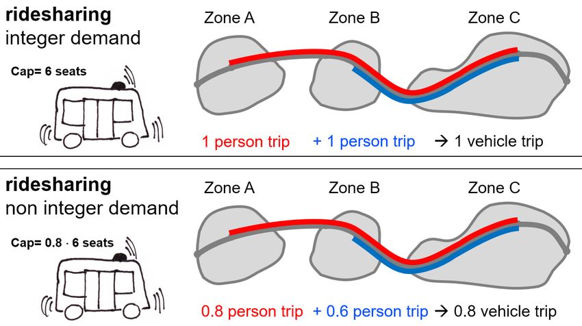
Document Control Page
Title                                          Guide for the simulation of AVs with a macroscopic modelling tool

Creator                                        Jörg Sonnleitner

Editor                                         Jörg Sonnleitner, Markus Friedrich

Brief Description                              Guide for using the tools for the macroscopic modelling of AVs

Publisher

                                               Jörg Sonnleitner, Markus Friedrich, Maximilian Hartl, Johann Hartleb,
Contributors
                                               Emely Richter, Alexander Migl (University of Stuttgart)

Type (Deliverable/Milestone)                   Deliverable

Format                                         Document

Creation date                                  2018-10-08

Version number                                 5.0

Version date                                   2020-02-05

Last modified by                               Jörg Sonnleitner

Rights

                                                     Internal

Audience                                             Public
                                                     Restricted, access granted to: EU Commission

                                                  To be revised by Partners involved in the preparation of the
                                               Deliverable

Action requested                                     For approval of the WP Manager
                                                     For approval of the Internal Reviewer (if required)
                                                     For approval of the Project Co-ordinator

Deadline for approval                          2018-10-31

Version           Date                         Modified by                           Comments
5.0               2020-02-05                   Jörg Sonnleitner                      Revision to include guidance for Visum 2020

          This project has received funding from the European Union’s Horizon 2020                          h2020-coexist.eu Page 2 of 47
          research and innovation programme under grant agreement No. 723201
Table of contents
Abbreviations .................................................................................................... 5
1 Introduction ................................................................................................ 5
1.1 Purpose of this document .................................................................................................. 5
1.2 Scope ................................................................................................................................ 5
1.3 Overview............................................................................................................................ 5
2 Impacts of CAV on capacity and network performance .......................... 7
2.1 Purpose ............................................................................................................................. 7
2.2 Approach ........................................................................................................................... 7
2.3 Instructions ........................................................................................................................ 9
2.3.1 Visum 18 or lower .................................................................................................................10
2.3.2 Visum 2020 ..........................................................................................................................17
2.4 Recommendations........................................................................................................... 20
3 Perception of automated travel time ...................................................... 22
3.1 Purpose ........................................................................................................................... 22
3.2 Approach ......................................................................................................................... 22
3.3 Instructions ...................................................................................................................... 28
3.3.1 Visum 18 or lower .................................................................................................................28
3.3.2 Visum 2020 ..........................................................................................................................32
3.4 Recommendations........................................................................................................... 33
4 Ridematching ........................................................................................... 35
4.1 Purpose ........................................................................................................................... 35
4.2 Approach ......................................................................................................................... 35
4.3 Instructions ...................................................................................................................... 36
4.4 Recommendations........................................................................................................... 37
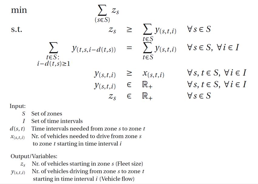
5 Vehicle scheduling................................................................................... 38
5.1 Purpose ........................................................................................................................... 38
5.2 Approach ......................................................................................................................... 38
5.3 Instructions ...................................................................................................................... 40
5.4 Recommendations........................................................................................................... 41
6 Next steps ................................................................................................. 42
This project has received funding from the European Union’s Horizon 2020 h2020-coexist.eu Page 3 of 47
research and innovation programme under grant agreement No. 723201
7     Literature .................................................................................................. 43
8     Appendix .................................................................................................. 44
8.1 How to create user-defined volume-delay functions ........................................................ 44

           This project has received funding from the European Union’s Horizon 2020      h2020-coexist.eu Page 4 of 47
           research and innovation programme under grant agreement No. 723201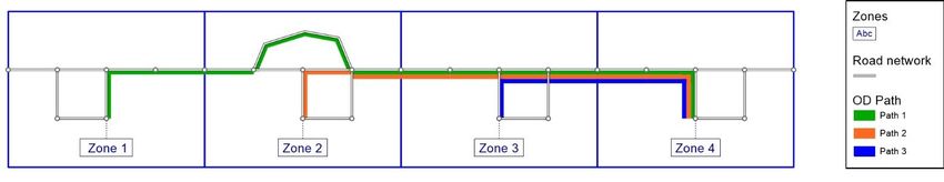
Abbreviations
Abbreviation           Long form
AV                     automated vehicle
CV                     conventional vehicle
PCU                    passenger car unit
VDF                    volume-delay function
HDV                    heavy duty vehicle
OD                     origin-destination
                       University of Stuttgart – Chair of Transport
USTUTT
                       Planning and Traffic Engineering

1 Introduction
1.1 Purpose of this document
This document provides guidance for modellers and model users for integrating automated vehicles (AV)
and their impacts into macroscopic travel demand models. To capture the capability of AV on different
levels, macroscopic models must be extended, which requires new methods or the application of tools.

1.2 Scope
This document sets the framework for the tools presented in D2.7 by introducing the ideas and approaches
together with assumptions to include AV in macroscopic travel demand models. Furthermore, it contains
practical advice and further recommendations for modellers.

While the tools described in D2.7 have been designed specifically for the software Visum, the approaches
presented in this document may also be used for other macroscopic simulation tools as well.

The application of the tools described represent extensions to Visum by adding functionality to the software
in form of Visum compatible scripts, Visum procedure files or Visum Add-Ins. The model user must plug
them into Visum to make them work and to perform a certain task. They assist the model developer or
model user by extending the capabilities of Visum. Apart from the automation of some tasks, the modeller
still needs to adapt settings or adjust parts in Visum that cannot be accessed in another way. Therefore, it
is required that the model user is familiar with working with Visum.

1.3 Overview
Traditional travel demand models apply the four-stage algorithm, where trip generation, destination choice,
mode choice and route choice are covered to replicate people’s behaviour and their movement. Departure

          This project has received funding from the European Union’s Horizon 2020   h2020-coexist.eu Page 5 of 47
          research and innovation programme under grant agreement No. 723201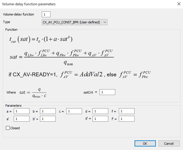
time choice may also be considered as a step. Integrating AV or new mobility services into these models
requires to establish and include new steps in the procedure. This could be for example the pooling of trips
as well as the scheduling of vehicles for a ridesharing system with self-driving vehicles. Besides adding
new model stages, impacts of AV on supply and demand must be taken into account on all stages of a
travel demand model.

Figure 1 shows the extended sequence of a travel demand model, which includes assumed impacts of
AV. Topics covered in this document are labelled with the corresponding chapters. Each main chapter
starts with an introduction where the purpose of the specific topic is discussed. The following chapters
outline ideas on how to approach the topic or problem in general, practical instructions on the
implementation into Visum and further recommendations.

Chapter 6 covers a brief overview on the macroscopic use cases and which tools they incorporate.

Figure 1: Modelling AV with macroscopic travel demand models

          This project has received funding from the European Union’s Horizon 2020   h2020-coexist.eu Page 6 of 47
          research and innovation programme under grant agreement No. 723201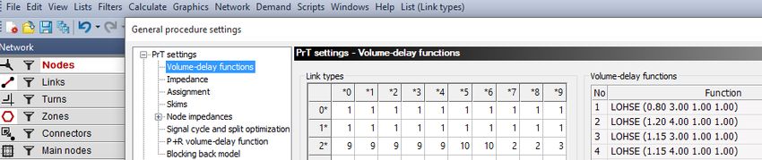
2 Impacts of CAV on capacity and network
performance
2.1 Purpose
CAV may change the capacity and performance of the road network. This section explains how the impacts
of CAV on capacity can be modelled in a macroscopic travel demand model.
2.2 Approach
The American Highway Capacity Manual (HCM, 2010) defines road capacity as the maximum sustainable
hourly flow rate at which persons or vehicles reasonably can be expected to traverse a point or a uniform
section of a lane or roadway during a given time period under prevailing roadway, environmental, traffic
and control conditions. This definition treats capacity more or less as a constant value. Brilon et al. (2007)
indicate that this assumption is not appropriate as observations show, that the maximum traffic throughput
varies even under constant external conditions. They introduce the concept of stochastic capacities to
replicate the relationship between traffic flows and traffic breakdown in a better way. Lohmiller (2014)
shows that the throughput on a motorway depends on the traffic composition, i.e. the driver population
influences the quality of the traffic flow. This leads to two interpretations for the relationship between
demand, capacity and performance. The performance, which can be measured by the indicator delay time
per vehicle, depends either on variable capacity values or on the ability of a given demand composition
(driver / vehicle population) to use a given (constant) capacity.
Macroscopic route choice and assignment models for private transport apply volume-delay functions to
determine travel time in the road network. For links, the travel time is computed by multiplying the free flow
travel time with a factor that is determined by a volume-delay function (VDF) as shown in equation (1). For
nodes, a delay time is added to the free flow travel time as shown in equation (2). Equation (3) presents a
simple example of a VDF. The VDF-factor depends on the volume / capacity ratio, i.e. the saturation rate
xs of a supply element s, which represents either a link or a node. The relationship between volume and
capacity is described in equation (4). It uses the concept of passenger car units (PCU) where capacity and
vehicle volumes are converted into passenger car equivalents. Examples for vehicle type specific PCU
values are 1.0 for conventional passenger cars, 2.3 for heavy goods vehicles and 0.4 for motorcycles
(Kimber et al. 1982).
tslink xs tsfree VDF xs (1)
tsnode xs tsfree VDF xs (2)
VDF xs 1 xs (3)
This project has received funding from the European Union’s Horizon 2020 h2020-coexist.eu Page 7 of 47
research and innovation programme under grant agreement No. 723201 qs ,i fi PCU
xs iVehType max (4)
qs
where
ts xs travel time on supply element s at saturation rate xs [sec]
t sfree travel time on supply element s at saturation rate xs 0 [sec]
VDF xs volume-delay function with parameters and
xs saturation rate (volume/capacity ratio) on supply element s [-]
capacity of supply element s assuming that all vehicles are conventional pass.
q smax
cars [PCU/h]
f i PCU PCU of vehicle type i [PCU/veh]
The concept of PCU is a common concept in macroscopic assignment models. It is mainly used to convert
heavy goods vehicles (HGV) into PCU. Assuming that AV have a performance that differs from
conventional cars (CV) and that the performance additionally depends on the type of supply element, the
PCU concept must be extended to AV as well as to road and intersection types (motorway or urban road,
grade separated or at-grade intersections, signalized or unsignalized intersections). Since the PCU-factor
will be multiplied with the volume of the related vehicle type, it is possible to model the impacts of different
penetration rates of AV.
This extension can come in two forms making different assumptions. The first approach assumes a linear
relationship between the share of AV and its impact on saturation. This requires a specific but constant
PCU-factor for each combination of vehicle type and supply element type as shown in equation (5). In this
first approach the PCU-factor does not depend on the share of AV. The second approach assumes a
nonlinear relationship. In case of a low penetration rate the influence of a single AV is smaller than in cases
with a higher penetration rate. To achieve this the PCU-factor must be adapted during an assignment
depending on the AV share on the related supply element using equation (6). Its value ranges between
the PCU-factors for an AV share of 0% and 100%.
iVehType
q f
s ,i
f f s ,i
PCU
linear impact AV
xs where (5)
f f s ,i ( ps , AV )
max PCU
q s nonlinear impact AV
,i AV ( ps , AV ) f s ,i AV
f sPCU PCU ,0%
ps , AV f sPCU ,0%
,i AV f sPCU ,100%
,i AV (6)
where
This project has received funding from the European Union’s Horizon 2020 h2020-coexist.eu Page 8 of 47
research and innovation programme under grant agreement No. 723201f sPCU
,i PCU of vehicle type i on type of supply element s [PCU/veh]
f sPCU
,i ( ps, AV ) PCU function dependent on the share of AV ps,AV [PCU/veh]
ps , AV AV share on supply element s
PCU of vehicle type AV on supply element type s for an AV-share of 0%
f sPCU ,0%
,i AV
[PCU/veh]
PCU of vehicle type AV on supply element type s for an AV-share of 100%
f sPCU ,100%
,i AV
[PCU/veh]
q s ,i volume of vehicle type i on supply element s [veh/h]
capacity of supply element s assuming that all vehicles are conventional
q smax
pass. cars [PCU/h]
VehType set of vehicle types: CV, AV, HGV
This approach is valid for AV-ready supply elements. For supply elements that are not AV-ready, the driver
has to take over control of the vehicle and the PCU would be 1 as for CV.
2.3 Instructions
This chapter comprises instructions and remarks for applying the tools provided for integrating impacts of
AV on capacity and network performance in Visum travel demand models. Some steps include the use of
scripts which are available as code in deliverable D2.7, but it is also possible for the model user to do
everything manually. In principle, almost everything can be done by scripts, but these depend in detail on
model properties and would always have to be rewritten by other users, so the authors refrain from doing
everything possible by scripts within this guide.
The prefix ‘CX_’ is introduced to uniquely identify all attributes, matrices, network elements or anything
else to be part of CoEXist-specific methods.
Prerequisites
A travel demand model in Visum with set VDF for each link type and capacities for each link where
Car is a permitted transport system.
A travel demand matrix for motorized vehicles.
There is no specific requirement regarding the Visum version. The screenshots are taken out of
Visum 17, but the approach with the provided VDF was successfully tested with Visum 14, 15, 16,
17 and 18.
For Visum 2020, a new set of VDF was necessary due to fundamental changes in the functionality
and structure of user-defined VDF. They are included in the revised version of Deliverable D2.7.
This project has received funding from the European Union’s Horizon 2020 h2020-coexist.eu Page 9 of 47
research and innovation programme under grant agreement No. 723201Limitations of Visum 18 or lower
The current solution can only handle one transport system of type “AV”. This limitation comes from the
capability of user-defined VDF in Visum, which support only a limited number of user-defined parameters
(AddVal1, AddVal2, AddVal3 and AddVal-TSys). Each new “AV” transport system with a different set of
PCU-factors and a different AV-ready network needs at least two, rather three own parameters that require
user input.
With additional assumptions and restrictive simplifications it is possible to include multiple “AV” transport
systems, but at this point it will not be discussed further.
Disclaimer: This document has been updated to provide guidance for Visum 2020 users as well.
Therefore, instructions are available separately for Visum 2020 in chapter 2.3.2. Besides some changes
in scripts or coding of VDF that are necessary due to structural changes of the software, some other steps
may deviate from the counterpart in chapter 2.3.1. Based on the experience of the last two years in
modeling AV, the updated instructions for Visum 2020 represent the approach that the authors would
currently recommend.
2.3.1 Visum 18 or lower
It is recommended to carry out the instructions in the suggested order as the tools partly depend on each
other. Any other sequence or modifications of names can cause errors in the modelling process or require
additional effort from the model user.
Go to menu Demand – TSys/Modes/DSeg and create a transport system for AV CX_AV as shown
in Figure 2.
Transfer the network attributes like speed and authorization for using links etc. from CV to AV.
Do not alter the value for PCU of 1.00, this will be done in another way and only for AV-ready links,
by default it should be the same as for CV.
Create a mode and a demand segment with the same name automatically (see also Figure 3).
Run the script for creating user-defined attributes (see Figure 4 for help)
“CoEXist_Create_User-Defined_Attributes_-_Extension_for_handling_AV_in_volume-
delay_functions.vbs”.
The script will add six attributes. Check if they have been added by opening the list of user-defined
attributes (Network – User-defined attributes), sorting by AttID and comparing to the attributes
listed in Table 1 and shown in Figure 5.
This project has received funding from the European Union’s Horizon 2020 h2020-coexist.eu Page 10 of 47
research and innovation programme under grant agreement No. 723201Figure 2: Create a new transport system for AV
Figure 3: Create new mode and demand segment for AV
Figure 4: Run a script file in Visum
This project has received funding from the European Union’s Horizon 2020 h2020-coexist.eu Page 11 of 47
research and innovation programme under grant agreement No. 723201Table 1: Overview about user-defined attributes
attribute object input description
CX_AV_READY link type by user 0: link type is not AV-ready, 1: link type is AV-ready
CX_AV_READY link by user 0: link is not AV-ready, 1: link is AV-ready
CX_AV-SHARE network by user fixed AV share as a percentage for splitting the demand
CX_F_PCU_AV_A link type by user PCU factor A for AV, which can be used stand-alone
PCU factor B for AV, which can be used additionally to factor A for a
CX_F_PCU_AV_B link type by user
varying resulting PCU factor depending on the AV share
CX_ID matrix by user CoEXist-unique identifier for working with formula matrices
Figure 5: User-defined attributes for handling AV in volume-delay functions in Visum
To make sure the script for adding formula matrices works properly, identify the demand matrix for
car driver as calculated by the travel demand model and set the matrix attribute CX_ID to
CX_CAR_DEMAND. CX_ID represents a unique identifier as short text for matrices altered or used
for CoEXist purposes and prevents conflicts with other attributes.
Run the script “CoEXist_Create_Formula_Matrices_-_Extension_for_handling_AV_in_volume-
delay_functions.vbs” for creating formula demand matrices for CV and AV out of original demand
matrix for car driver.
As a result, there should be two new matrices. Matrix CX_CV_DEMAND will contain the demand
of conventional vehicles, Matrix CX_AV_DEMAND the demand for AV. The user must define the
share of the total travel demand by car drivers that is assigned to each matrix. Check the success
of the script by comparing the formula matrices with Figure 6. The numbering of the matrices is not
relevant for the further steps. The script uses the next numbers available. Model users may change
the number after running the script.
This project has received funding from the European Union’s Horizon 2020 h2020-coexist.eu Page 12 of 47
research and innovation programme under grant agreement No. 723201Figure 6: New formula demand matrices for CV and AV demand
Choose these new matrices as input for the demand segments CX_AV and the one already in
usage for CV in menu Demand – Demand data – Demand segments as shown in Figure 7
Figure 7: Select new demand matrices in OD demand data settings
Load the procedure parameters (see Figure 8 for guidance)
“CoEXist_Procedure_Parameters_-_Extension_for_handling_AV_in_volume-
delay_functions.xml”.
Figure 8: Load procedure parameters in Visum
Figure 9 shows the corresponding dialogue that appears. Uncheck the box for loading General
procedure settings and choose to insert the operations after a desired procedure step. It makes
sense to place them in the beginning of the procedure sequence to be sure that the AV-related
attributes are set before any skim or demand calculation.
This project has received funding from the European Union’s Horizon 2020 h2020-coexist.eu Page 13 of 47
research and innovation programme under grant agreement No. 723201Figure 9: Dialogue for reading procedure parameters
A procedure group consisting of five operations as shown in Figure 10 is inserted. Some of them
are deactivated by default. Here, the attribute for AV-readiness is transferred from link type level.
Assuming the impact of one AV to be independent of the AV share, PCU-factor A is the only one
considered.
Figure 10: Added group of operations in procedure sequence
Table 2 shows which user-defined attributes correspond to the attributes accessed by the VDF and
the variables introduced in the approach in Chapter 2.2.
Table 2: Variables used in approach and corresponding attributes in Visum
variable in approach user-defined attribute attribute accessed by VDF network element level
- not used - CX_AV_READY AddVal1 link type or link
f sPCU ,Min
,i AV CX_F_PCU_AV_A AddVal2 link type
f sPCU ,Max
,i AV CX_F_PCU_AV_B AddVal3 link type
There are default values set for the new attributes on link type level as shown in Figure 11. The
user needs to decide which link types or links should be AV-ready. Set CX_AV-READY = 1, if a
link type is AV-ready, i.e. AV show a different performance than CV. Additionally, the relevant PCU-
factors need to be set for the AV-ready link types. PCU-factors for link types that are not AV-ready
(CX_AV-READY = 0) do not have any effect on traffic performance.
This project has received funding from the European Union’s Horizon 2020 h2020-coexist.eu Page 14 of 47
research and innovation programme under grant agreement No. 723201Figure 11: Link type list with new user-defined attributes
If the AV-readiness is based on links instead of link types, the attribute CX_AV-READY on link type
level is irrelevant. The user then needs to define CX_AV-READY on link level, but still the PCU-
factors must be set on link type level. Furthermore, the procedures concerned must be activated
or deactivated respectively: this means the user must activate either procedure 7 or 8 in the
procedure sequence shown in Figure 10. Both operations transfer the values of CX_AV-READY to
AddVal1.
Place the DLL and corresponding BMP files for all volume-delay functions that should be
considered under the directory
“C:\User\...\AppData\Roaming\PTV Vision\PTV Visum 17\UserVDF-DLLs\”.
If the Visum application is still running, please save the current version file, close and restart the
application. Otherwise the functions will not be detected and available for usage in Visum.
Most settings related to VDF can be found under
Calculate – General procedure settings – PrT settings – Volume-delay functions (see Figure 12).
It is recommended not to alter the present functions, but to create new ones with the user-defined
VDF types. The table Link types must also be adjusted accordingly.
The following VDF are included in D2.7 and should be available to select, if placed under the proper
directory:
o VisumVDF_CX_AV_PCU_CONST_BPR_x64.dll
o VisumVDF_CX_AV_PCU_CONST_LOHSE_x64.dll
o VisumVDF_CX_AV_PCU_VAR_BPR_x64.dll
o VisumVDF_CX_AV_PCU_VAR_LOHSE_x64.dll
Figure 12: Settings for volume-delay functions in the general procedure settings
The basic characteristics of the provided VDF types are listed in Table 3 below.
This project has received funding from the European Union’s Horizon 2020 h2020-coexist.eu Page 15 of 47
research and innovation programme under grant agreement No. 723201Table 3: Overview on user-defined VDF types provided in D2.7
VDF type – DLL basic type impact of one AV
VisumVDF_CX_AV_PCU_CONST_BPR_x64 BPR constant, fixed PCU
VisumVDF_CX_AV_PCU_CONST_LOHSE_x64 LOHSE constant, fixed PCU
VisumVDF_CX_AV_PCU_VAR_BPR_x64 BPR variable, PCU depending on AV-share
VisumVDF_CX_AV_PCU_VAR_LOHSE_x64 LOHSE variable, PCU depending on AV-share
Please note that these function types are tailored for the transport systems of the Stuttgart Region
travel demand model, i.e. the code for the transport system car is P and additional six HDV
transport systems are considered within the calculation. Models with different codes for transport
systems need a VDF that takes these into account. Guidance for creating or editing function types
can be found under Chapter 8.1 in the appendix.
After selecting a function type, the user must set parameters. Any representation of a user-defined
function should clearly show which parameters are taken into account for calculations Figure 13
shows a function type which includes the parameters a, b and c. Please note that in the expression
for saturation, the German terms for Car (Pkw) and HDV (Lkw) are used.
When selecting any user-defined VDF, all parameters are displayed as available, independent of
a possible incorporation in the calculation rule. Altering the parameters not used in the function
type does not affect any results.
The equation regarding the saturation shown in the ‘Function’-Box at the bottom is fixed and cannot
be removed.
Add the transport system CX_AV to all PrT Assignment operations in the procedure sequence. Do
not consider the mode CX_AV for travel demand calculation or mode choice. The demand for AV
is generated out of the demand for ‘Car driver’ as before.
Since the AV-related attributes are transferred to AddVal1/AddVal2/AddVal3, do not forget to check
whether these are used for any other purposes. If this is the case, shift them to new user-defined
attributes.
Start the procedure sequence and run all active operations.
This project has received funding from the European Union’s Horizon 2020 h2020-coexist.eu Page 16 of 47
research and innovation programme under grant agreement No. 723201Figure 13: Type, representation of calculation rule and parameters for selected volume-delay function
Afterwards, check if the expected changes have occurred. For this purpose, there is an Excel
template that might be helpful. It is provided by PTV included in the Visum installation located under
the directory
“C:\Program Files\PTV Vision\PTV Visum 17\Doc\Eng\VolumeDelay_functions.xlsx”
and includes calculations and charts for several VDF types, where the user can set the parameters
as desired to easily compare current travel times.
2.3.2 Visum 2020
It is recommended to carry out the instructions in the suggested order as the tools partly depend on each
other. Any other sequence or modifications of names can cause errors in the modelling process or require
additional effort from the model user.
Go to menu Demand – TSys/Modes/DSeg and create a transport system for AV CX_AV as shown.
Transfer the network attributes like speed and authorization for using links etc. from conventional
cars to AV.
Do not alter the value for PCU of 1.00, this will be done in another way and only for AV-ready links,
by default it should be the same as for CV.
Create a mode and a demand segment with the same name automatically.
This project has received funding from the European Union’s Horizon 2020 h2020-coexist.eu Page 17 of 47
research and innovation programme under grant agreement No. 723201 Run the script for creating user-defined attributes
“CoEXist_Create_User-Defined_Attributes_-_Extension_for_handling_AV_in_volume-
delay_functions_Visum2020.vbs”.
The script will add five attributes. Check if they have been added by opening the list of user-defined
attributes (Network – User-defined attributes) and comparing to the attributes listed in Table 4.
Table 4: Overview about user-defined attributes
attribute object input description
CX_AV_READY link by user 0: link is not AV-ready, 1: link is AV-ready
CX_F_PCU_AV_1 link by user PCU factor 1 for AV, which can be used stand-alone
PCU factor 0 for AV, which can be used additionally to factor 1 for a
CX_F_PCU_AV_0 link by user
varying resulting PCU factor depending on the AV share
CX_AV-SHARE network by user fixed AV share as a percentage for splitting the demand
CX_ID matrix by user CoEXist-unique identifier for working with formula matrices
User-defined Volume-delay functions (VDF) provided in D2.7 assuming a constant PCU factor for
each AV (“VisumVDF_CX_AV_PCU_CONST_..._2020_x64.dll”) use CX_F_PCU_AV_1 and VDF
assuming a share-dependent PCU factor (“VisumVDF_CX_AV_PCU_VAR_..._2020_x64.dll “)
make usage of both PCU attributes. Then, CX_F_PCU_AV_1 corresponds to the PCU value of
each AV for 100% AV share and CX_F_PCU_AV_0 accordingly to the PCU value for 0% AV. In
between the used PCU factor follows a linear course according to the AV share.
There are default values set for the new attributes on link type level. The user needs to decide
which links should be AV-ready. Set CX_AV-READY = 1, if a link is AV-ready, i.e. AV show a
different performance than CV. Additionally, the relevant PCU-factors need to be set for the AV-
ready links. PCU-factors for links that are not AV-ready (CX_AV-READY = 0) do not have any
effect on traffic performance as those are not considered by the VDF.
To make sure the script for adding formula matrices works properly, identify the demand matrix for
car driver as calculated by the travel demand model and set the matrix attribute CX_ID to
CX_CAR_DEMAND. CX_ID represents a unique identifier as short text for matrices altered or used
for CoEXist purposes and prevents conflicts with other attributes.
Run the script “CoEXist_Create_Formula_Matrices_-_Extension_for_handling_AV_in_volume-
delay_functions_Visum2020.vbs” for creating formula demand matrices for CV and AV out of
original demand matrix for car driver.
As a result, there should be two new matrices. Matrix CX_CV_DEMAND will contain the demand
of conventional vehicles, Matrix CX_AV_DEMAND the demand for AV. The user must define the
share of the total travel demand by car drivers that is assigned to each matrix. The numbering of
the matrices is not relevant for the further steps. The script uses the next numbers available. Model
users are free to change the number after running the script.
Choose these new matrices as input for the demand segments CX_AV and the one already in
usage for CV in menu Demand – Demand data – Demand segments.
This project has received funding from the European Union’s Horizon 2020 h2020-coexist.eu Page 18 of 47
research and innovation programme under grant agreement No. 723201 Load the procedure parameters
“CoEXist_Procedure_Parameters_-_Extension_for_handling_AV_in_volume-
delay_functions_Visum2020.xml”.
A corresponding dialogue appears: Uncheck the box for loading General procedure settings and
choose to insert the operations after a desired procedure step. It makes sense to place them in the
beginning of the procedure sequence to be sure that the AV-related attributes are set before any
skim or demand calculation.
A procedure group consisting of one operation is inserted. With the operation on editing a network
attribute, the AV share is set. Unlike with Visum 18 or older software versions, it is no longer
necessary to transfer the attribute information on AV-readiness or PCU values to AddVals because
the VDF is able to access these attributes now directly on link level.
Place the DLL and corresponding BMP files for all volume-delay functions that should be
considered under the directory
“C:\User\...\AppData\Roaming\PTV Vision\PTV Visum 2020\UserVDF-DLLs\”.
If the Visum application is still running, please save the current version file, close and restart the
application. Otherwise the functions will not be detected and available for usage in Visum.
Most settings related to VDF can be found under
Calculate – General procedure settings – PrT settings – Volume-delay functions.
It is recommended not to alter the present functions, but to create new ones with the user-defined
VDF types. The table Link types must also be adjusted accordingly.
The following VDF are also included in the revised D2.7 and should be available to select, if placed
under the proper directory:
o VisumVDF_CX_AV_PCU_CONST_BPR_2020_x64.dll
o VisumVDF_CX_AV_PCU_CONST_LOHSE_2020_x64.dll
o VisumVDF_CX_AV_PCU_VAR_BPR_2020_x64.dll
o VisumVDF_CX_AV_PCU_VAR_LOHSE_2020_x64.dll
The basic characteristics of the provided VDF types correspond to those shown in Table 3.
Please note that these function types are tailored for the transport systems of the Stuttgart Region
travel demand model, i.e. the code for the transport system car is P and additional six HDV
transport systems are considered within the calculation. Models with different codes for transport
systems need a VDF that takes these into account. Guidance for creating or editing function types
can be found under Chapter 8.1 in the appendix.
After selecting a function type, the user must set parameters. Any visual representation of a user-
defined function should clearly show which parameters are taken into account for calculations. For
the VDF provided, the parameters a, b, c and satcrit are used as in usual BPR or LOHSE functions.
When selecting any user-defined VDF, all parameters are displayed as available, independent of
a possible incorporation in the calculation rule. Altering the parameters not used in the function
type does not affect any results.
The equation regarding the saturation shown in the ‘Function’-Box at the bottom is fixed and cannot
be removed.
Add the transport system CX_AV to all PrT Assignment operations in the procedure sequence. Do
not consider the mode CX_AV for travel demand calculation or mode choice. The demand for AV
is generated out of the demand for ‘Car driver’ as before.
Start the procedure sequence and run all active operations.
This project has received funding from the European Union’s Horizon 2020 h2020-coexist.eu Page 19 of 47
research and innovation programme under grant agreement No. 723201 Afterwards, check if the expected changes have occurred. For this purpose, there is an Excel
template that might be helpful. It is provided by PTV included in the Visum installation located under
the directory
“C:\Program Files\PTV Vision\PTV Visum 2020\Doc\Eng\VolumeDelay_functions.xlsx”
and includes calculations and charts for several VDF types, where the user can set the parameters
as desired to easily compare current travel times.
2.4 Recommendations
The following list of recommendations for applied settings for user-defined VDF incorporating the impact
of AV on network performance as described in the previous chapters represents the current state of the
art and should not be considered as immutable:
Do not alter values for capacity, since these are justifiably set and the model was calibrated and
validated with these capacities.
The basic type of the VDF should remain as it is (BPR, LOHSE, etc.) for each link type.
Providing exemplary user-defined VDF types including BPR or LOHSE does not imply that these
are recommended by USTUTT in any sense.
Adopt the same values for related parameters (a, b, c, satCrit, etc.) for VDF types additionally
considering AV of those that considered CV only before.
Example:
VDF with the number 4 was a common BPR type with the parameters a=2, b=3, c=1 used for link
types 10-29.
Create a new VDF which takes AV into account with the basic type of BPR and the same parameter
values a=2, b=3, c=1. Assign the number of this new VDF to the link types 10-29.
To keep a good orderliness, choose a number for each new VDF consequently for all VDF that
should be replaced, e.g. current VDF numbers 1, 2, 3 and 4 new numbers 11, 12, 13 and 14.
Instructions, hints and troubleshooting for creating user-defined VDF can be found in Chapter 8.1 in the
appendix.
Table 5 shows the derived PCU factors for the driving logics cautions, normal and all-knowing. Those
represent the respective AV capabilities. The values are extracted from estimated capacities of
microscopic traffic flow simulations conducted by PTV. More information is available in the report on
Milestone 16 that is included in the Appendix of Deliverable 2.7.
Table 5: PCU factors for three types of AV driving behaviour depending on the roadway
Roadway Cautious Normal All-knowing
Motorway 1.20 0.77 0.73
Arterial 1.26 0.81 0.76
Urban street 1.32 0.85 0.79
This project has received funding from the European Union’s Horizon 2020 h2020-coexist.eu Page 20 of 47
research and innovation programme under grant agreement No. 723201Table 6 shows which driving behavior is used by each AV class on the different roadway types. Combining
Table 5 and Table 6 results in Table 7, showing the PCU values for each AV class and roadway. It is
expected that a vehicle of the first generation of AV (Basic AV) will be able to handle situations on
motorways and on arterials on its own with high caution, while on urban streets it is still necessary to drive
manually. That is the reason why the PCU of a Basic AV on urban streets corresponds to 1.0, the default
PCU for conventional vehicles. For Intermediate AV the capability to operate in automated mode will be
extended to urban road environments. Additionally, the included highway pilot doesn’t need a driver as a
fall back on motorways anymore. Finally, the Advanced AV is capable to handle driving in all three road
environments on its own, yet it is still not able to manage all situations under all circumstances, which is
why it is not a driverless vehicle.
Table 6: AV driving behaviours depending for each AV class and roadway type
Roadway Basic AV Intermediate AV Advanced AV
Motorway Cautious Normal All-knowing
Arterial Cautious Normal All-knowing
Urban street Manual Cautious Normal
Table 7: Resulting PCU factors for three types of AV for three types of roadway
Roadway Basic AV Intermediate AV Advanced AV
Motorway 1.20 0.77 0.73
Arterial 1.26 0.81 0.76
Urban street 1.00 1.32 0.85
It needs to be stressed that the values in Table 7 only hold if the respective roadway types are considered
to be automation-ready. If the model user wants to model impacts of AV for the assumption that these can
only drive automated on motorways and motorway-similar roads, the PCU factors for the other roadway
types need to correspond to 1.0.
More information on the definitions for the AV types is available in Deliverable 1.4.
This project has received funding from the European Union’s Horizon 2020 h2020-coexist.eu Page 21 of 47
research and innovation programme under grant agreement No. 7232013 Perception of automated travel time
3.1 Purpose
Automated travel time corresponds to the time during which the vehicle takes control of the driving task.
Car drivers in a CAV of level 3 and higher may use some of their driving time for non-driving activities.
This may decrease the perceived travel time of a car trip and improve the benefits of car usage leading to
changes in route choice, mode choice and destination choice. This section explains how the impacts of
CAV on perceived travel time can be modelled in a macroscopic travel demand model.
3.2 Approach
The approach consists of two parts. The first deals with the idea on how the perceived travel times of CV
and AV are merged in theory. The second part presents a way to implement the methodology into a travel
demand model using formula matrices. The prefix CX is introduced to identify all attributes, matrices,
network elements or anything else to be part of CoEXist-specific methods within Visum.
Travel demand models replicate the decision making process of individual travellers concerning the choice
of destination, mode and route. In each choice situation travellers select from a set of choices. A utility
function describes the utility of each choice considering the characteristics of the trip maker (user group)
and the trip purpose (activity). These functions consider various time components (access, egress, driving,
waiting, parking search), cost and travel comfort. Each component is weighted with a specific factor. For
current transport modes, these factors can be estimated by mobility surveys. For choices with AV, the
functions as well as the choice set need to be adjusted in a suitable way.
At the levels 3 and 4 AV still require a driver as fallback. Consequently, the set of choices remains more
or less similar to the situation without AV. However, the attributes of a choice change for the mode car-
driver. The value of time experienced in an AV differs from the value of time spent in a CV, because the
driver can spend some time of the trip duration on other tasks than driving. If AV of level 3 and 4 can only
drive automatically on certain road types or on certified network sections, they probably have an impact
on route choice as well as mode choice. Such a behaviour can be integrated in existing travel demand
models by adding an additional transport system AV with a specific utility function for route choice.
This specific utility function resembles already existing functions for CV but is supplemented by another
factor s ≤ 1, which reduces the perception of travel time in an AV. Due to the fact that automated driving
t , AV
is only possible on certain parts of the road network, the factor needs to dependent on the road segment
s used by the AV. For road segments that allow automated driving s represents the reduced perception
t , AV
of time spent in an AV, whereas for road segments that do not provide the necessary design standard
there will be no reduced value of time for AV and therefore s is set to one. Equations (7) and (8) show
t , AV
how a weighted travel time vodr can be computed for CV and AV using the factor s .
t t , AV
This project has received funding from the European Union’s Horizon 2020 h2020-coexist.eu Page 22 of 47
research and innovation programme under grant agreement No. 723201t ,CV
vodr t todr
CV
(7)
t , AV
vodr st , AV t todrs
AV
(8)
sr
where
t ,CV t , AV
vodr vodr weighted travel time value for CV and AV for the route r from origin o to destination d [-]
,
t factor for travel time perception [1/s]
st , AV factor for travel time perception in an AV on supply element s [1/s]
CV
todr travel time with a CV for the route r from origin o to destination d [s]
AV
todrs travel time with an AV on supply element s as element of the route r from o to d [s]
As an input for travel time values and comfort of AV, one can think of using the values for high-speed trains
or survey based values. A study of de Looff et al. (2017), for example, focuses on the impacts of AV on
the value of travel time for commuting trips in the Netherlands. As a result for an AV with an office interior
they find a lower value (4.99 €/h) than for the conventional car (7.99 €/h). As indicated by Trommer et al.
(2016), the perception of time spent in AV may vary for different user groups and activities. Additionally,
reduced travel times from higher capacities and a reduced amount of time for parking because of valet
parking options for AV should be considered in the utility functions.
Integrating AV into an existing travel demand model can be achieved by replacing the travel time matrix
t ,Car
of CV by a travel time matrix V which is derived from the weighted travel time matrix of AV and CV. As
presented in Figure 14 and in equation (9) the aggregated weighted travel time for mode car driver is
derived by weighting the transport system-specific times with the share of AV in the car fleet p AV . This
share is an input value defined by the model user. Assuming that time usage depends on the duration of
the fully automated section a certain threshold value t (e.g. 10 minutes) can be set by the model user.
This project has received funding from the European Union’s Horizon 2020 h2020-coexist.eu Page 23 of 47
research and innovation programme under grant agreement No. 723201Figure 14: Derivation of the weighted travel time for the mode car driver from the transport systems AV and CV
1 p AV vod
t ,CV
p AV vod
t , AV
, if todAV ,automated t
t ,Car
vod (9)
vodt ,CV
, if todAV ,automated t
where
t ,Car
vod weighted travel time value for the mode car driver from origin o to destination d [-]
p AV share of AV in the car fleet [-]
t ,CV t , AV
vod vod weighted travel time of CV and AV respectively from origin o to destination d [-]
,
todAV ,automated part of the travel time of AV driven in automated mode on an OD-pair [min]
t threshold travel time to perceive an advantage for driving in automated mode [min]
This project has received funding from the European Union’s Horizon 2020 h2020-coexist.eu Page 24 of 47
research and innovation programme under grant agreement No. 723201How to compute and consider the perceived automated travel time in practice?
The basic assumption for the following approach is that the transport systems (traditional) ‘Car’,
consequently referred to as ‘CV’, and ‘AV’ are treated as part of the mode and demand segment ‘Car
driver’. Characteristics of trips made with one or the other both have to be taken into account for the
attractiveness of the mode. To get a new skim matrix for the demand segment ‘Car driver’, three parts
have to be considered:
‘Normally’ perceived travel time for all roads (CV)
‘Normally’ perceived travel time for roads that are not AV-ready (AV)
Automated travel time perceived differently on AV-ready roads (AV).
Figure 15 shows how the methodology is implemented in Visum on a simplified level. Two outputs from
the skim calculation of private transport are used for the further procedure: the current travel time for CV
(CV_TTC_CAR) and the sum of the AV-ready travel time (CX_TTC_AV-READY). The skim matrices
include aggregated values on OD-pair level according to the settings for the skim calculation, e.g.
weighting of paths: “mean over path volume”. The difference of the two matrices is the travel time of
vehicles on roads that are not AV-ready (CX_TTC_NOT_AV-READY).
Figure 15: Approach for handling perceived automated travel time in Visum with formula matrices
The AV-ready travel time is then converted to the perceived automated travel time according to the
calculation rule shown in equation (10). The modeller must decide about reasonable values for two
parameters:
This project has received funding from the European Union’s Horizon 2020 h2020-coexist.eu Page 25 of 47
research and innovation programme under grant agreement No. 723201 The ‘ramp-up time’ A , for which no reduction of the perceived time is assumed
The factor f perc that converts the travel time exceeding A to a perceived time by reducing it.
The result of this conversion is the matrix CX_TTC_AV-READY_PERCEIVED.
t , t A, f 1, c 0
t perc f t c (10)
f perc (t A) A , t A, f f perc , c A f perc A
where
t perc perceived automated travel time between two zones
t aggregated automated travel time between two zones
f multiplicative factor
c additive factor
A threshold A for in-vehicle time perception [min]
f perc factor for perception of automated travel time
Figure 16 shows that the factor multiplied with travel time is kept to 1 until the threshold A is reached.
Figure 16: Course of the multiplicative perception factor for increasing travel time
This project has received funding from the European Union’s Horizon 2020 h2020-coexist.eu Page 26 of 47
research and innovation programme under grant agreement No. 723201The resulting course for the perceived travel time is represented in Figure 17. Obviously, the gradient
significantly changes at time A . The effect of the factor f perc solely on the duration in addition to A
guarantees no jump discontinuity regarding the course of perceived travel time.
Figure 17: Perceived time in the course of increasing travel time
Merging the sum of the perceived AV-ready travel times and the not AV-ready travel times with the original
travel time matrix weighted by the global AV-share CX_AV-SHARE results in the matrix
CX_TTC_CV_x_AV. In the end, this matrix should be fed into trip distribution and mode choice.
Table 8 indicates the correlation between the relevant variables presented in the equation (10) and the
user-defined attributes in Visum. Inserting attributes and matrices for this approach is covered in the
following chapter.
Table 8: Variables used in approach and corresponding attributes in Visum
variable in approach user-defined attribute network element level
A CX_THRESHOLD_IVT_PERCEPTION_A network
f perc CX_IVT-PERCEPTION_FACTOR network
This project has received funding from the European Union’s Horizon 2020 h2020-coexist.eu Page 27 of 47
research and innovation programme under grant agreement No. 7232013.3 Instructions
This chapter comprises instructions and remarks for applying the tools provided for integrating differences
regarding the perception of travel time in conventional and automated vehicles in Visum travel demand
models. Some steps include the use of scripts which are available as code in deliverable D2.7, but it is
also possible for the model user to do everything manually. In principle, almost everything can be done by
scripts, but these depend in detail on model properties and would always have to be rewritten by other
users, so the authors refrain from doing everything possible by scripts within this guide.
Prerequisites
Travel demand model in Visum with PrT assignment and skim matrix calculation including travel
time for demand segment ‘Car driver’ in a loop within the procedure sequence before trip
distribution and mode choice are calculated.
There is no specific requirement regarding the Visum version. The screenshots are taken out of
Visum 17, but the approach was also successfully tested with older and newer software versions.
Disclaimer: This document has been updated to provide guidance for Visum 2020 users as well.
Therefore, instructions are available separately for Visum 2020 in chapter 3.3.2. Besides some changes
in scripts that are necessary due to structural changes of the software, some other steps have been revised
compared to the counterpart of older Visum software versions in chapter 3.3.1. Based on the experience
of the last two years in modeling AV, the updated instructions for Visum 2020 represent the approach that
the authors would currently recommend.
3.3.1 Visum 18 or lower
It is recommended to comply the instructions in the following order. The tools are partly based on each
other. Any other sequence or differing names can cause errors or additional subsequent effort for the
model user.
Go to menu Demand – TSys/Modes/DSeg and create a transport system for AV CX_AV as shown
in Figure 2 in chapter 2.3.
Transfer the network attributes like speed and authorization for using links etc. from CV for AV.
Create mode and demand segment with the same name automatically (see also Figure 3 in
Chapter 2.3).
Run the script file
“CoEXist_Create_User-Defined_Attributes_-
_Extension_for_perceived_automated_travel_time_impacts.vbs” to create seven new attributes.
Compare the list of user-defined attributes to Figure 18 and Table 9 to check if the script worked
properly.
Load the procedure parameter file
“CoEXist_Procedure_Parameters_-
_Extension_for_perceived_automated_travel_time_impacts.xml” and insert the operations to the
desired place in the procedure sequence, e.g. after initializing other attributes or assignments as
shown in Figure 19.
This project has received funding from the European Union’s Horizon 2020 h2020-coexist.eu Page 28 of 47
research and innovation programme under grant agreement No. 723201Table 9: Overview on user-defined attributes added by the script
attribute object origin description
CX_AV_READY link type by user 0: link type is not AV-ready, 1: link type is AV-ready
CX_AV_READY link by user 0: link is not AV-ready, 1: link is AV-ready
CX_AV-SHARE network by user fixed AV share as a percentage for splitting the demand
CX_ID matrix by user CoEXist-unique identifier for working with formula matrices
CX_IVT_PERCEPTION_ Factor for the perception of in-vehicle time in automated
network by user
FACTOR driving mode
CX_THRESHOLD_IVT- Threshold A for the perception of in-vehicle time in
network by user
PERCEPTION_A automated driving mode [min]
CX_TTC_AV-READY link formula Current travel time on AV-ready links [min]
Figure 18: User-defined attributes that should be added by running the script
Figure 19: Added group of operations for setting the relevant attribute values
The group of procedures contains operations to set values for attributes needed.
Add the operation Calculate PrT skim matrix for CX_AV right after the already existing Calculate
PrT skim matrix for ‘Car’ / ‘Car driver’ and activate the calculation for the skim User-defined as
shown in Figure 20. All other possible skims have to be deactivated.
This project has received funding from the European Union’s Horizon 2020 h2020-coexist.eu Page 29 of 47
research and innovation programme under grant agreement No. 723201Figure 20: Activate user-defined skim calculation for CX_AV
Set the Code for the user-defined skim to CX_TTC_AV-READY by selecting General procedure
settings – PrT settings – Skims – User-defined (see Figure 21). Decide about reasonable values
for the other editable settings (e.g. decimal places) according to the other skims included in your
model.
Edit the parameters of the user-defined skim by selecting Parameters in the box at the bottom (see
also Figure 21). On link level, choose CX_TTC_AV-READY divided by 60 to get minutes as unit
instead of seconds (default unit for data type precise duration of the link attribute CX_TTC_AV-
READY is seconds) as shown in Figure 22.
Execute the new PrT skim calculation procedure once: It is enough to start the execution and abort
it after a few seconds to get Visum to create the new user-defined skim matrix automatically with
the assigned code.
Identify this new skim matrix and set the value for the attribute CX_ID to CX_TTC_AV-READY.
Identify the skim matrix for the current travel time (TTC) of ‘Car’ / ‘Car driver’ and set its CX_ID to
CX_TTC_CAR.
Identify the demand matrix for ‘Car driver’ as calculated by the travel demand model and set its
CX_ID to CX_CAR_DEMAND
Run the script
“CoEXist_Create_Formula_Matrices_-
_Extension_for_perceived_automated_travel_time_impacts.vbs” to incorporate the prepared
formula matrices.
This project has received funding from the European Union’s Horizon 2020 h2020-coexist.eu Page 30 of 47
research and innovation programme under grant agreement No. 723201You can also read