PID controller for the control of air flows or differential pressures, model A2G-100 PID-Regelgerät zur Regelung von Volumenströmen oder ...
←
→
Page content transcription
If your browser does not render page correctly, please read the page content below
Operating instructions
                                    Betriebsanleitung

PID controller for the control of air flows or differential
                                                              EN
pressures, model A2G-100

PID-Regelgerät zur Regelung von Volumenströmen
                                                              DE
oder Differenzdruck, Typ A2G-100

                       Model A2G-100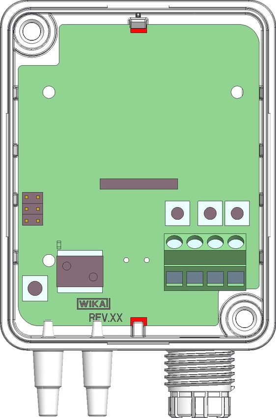
EN Operating instructions model A2G-100                           Page     3 - 42

DE Betriebsanleitung Typ A2G-100                                  Seite   43 - 81

   © 03/2018 WIKA Alexander Wiegand SE & Co. KG
   All rights reserved. / Alle Rechte vorbehalten.
   WIKA® is a registered trademark in various countries.
   WIKA® ist eine geschützte Marke in verschiedenen Ländern.

   Prior to starting any work, read the operating instructions!
   Keep for later use!
                                                                                     40414622.01 03/2018 EN/DE

   Vor Beginn aller Arbeiten Betriebsanleitung lesen!
   Zum späteren Gebrauch aufbewahren!

    2                                    WIKA operating instructions model A2G-100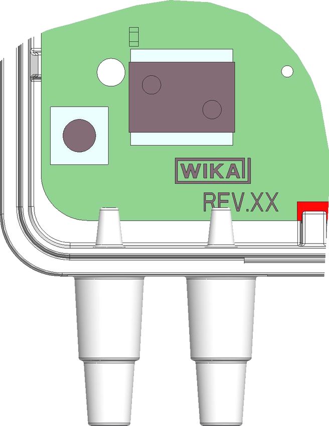
Contents

                            Contents                                                               EN

                            1. General information                                             4
                            2. Design and function                                             5
                            3. Safety                                                          6
                            4. Transport, packaging and storage                               11
                            5. Commissioning, operation                                       12
                            6. Menu navigation                                                20
                            7. Maintenance, cleaning and recalibration                        37
                            8. Dismounting, return and disposal                               38
                            9. Specifications                                                 41

                            Declarations of conformity can be found online at www.wika.com.
40414622.01 03/2018 EN/DE

                            WIKA operating instructions model A2G-100                          3
1. General information

     1. General information
     ■■ The PID controller described in the operating instructions has been
         manufactured using state-of-the-art technology. All components
EN       are subject to stringent quality and environmental criteria during
         production. Our management systems are certified to ISO 9001 and
         ISO 14001.

     ■■ These operating instructions contain important information on
         handling the instrument. Working safely requires that all safety
         instructions and work instructions are observed.

     ■■ Observe the relevant local accident prevention regulations and
         general safety regulations for the instrument's range of use.

     ■■ The operating instructions are part of the product and must be kept
         in the immediate vicinity of the instrument and readily accessible to
         skilled personnel at any time. Pass the operating instructions on to the
         next operator or owner of the instrument.

     ■■ Skilled personnel must have carefully read and understood the
         operating instructions prior to beginning any work.

     ■■ The general terms and conditions contained in the sales
         documentation shall apply.

     ■■ Subject to technical modifications.

     ■■ Further information:
         - Internet address:      www.wika.de / www.wika.com
                                  www.air2guide.com
         - Relevant data sheet: SP 69.11
                                                                                    40414622.01 03/2018 EN/DE

     4                                WIKA operating instructions model A2G-100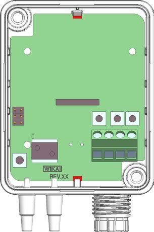
2. Design and function
2. Design and function
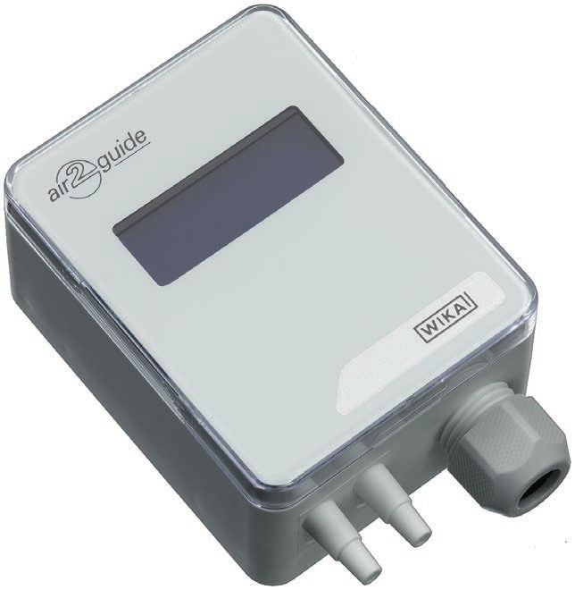
2.1 Overview
EN
Case
LC display
Cable gland M16
Connecting nozzle (ABS), for hoses with inner diameter 4 or 6 mm
2.2 Description
The model A2G-100 PID controller is used for the control of differential
pressures or air flows in ventilation and air-conditioning applications.
The 0 ... 10 V or 4 ... 20 mA control output is connected as control signal
directly to the EC ventilation fan or frequency inverter (FI). Its two-line
LC display simultaneously shows the direction of the monitoring output
and the current measured value. It provides analogue electrical output
signals of 0 ... 10 V or 4 ... 20 mA, which can be set by the operator via a
40414622.01 03/2018 EN/DE
jumper within the instrument.
WIKA operating instructions model A2G-100 5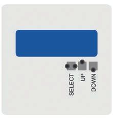
2. Design and function / 3. Safety

     2.3 Dimensions in mm

EN

                                                                      40405589.02

     2.4 Scope of delivery
     ■■ PID controller
     ■■ 2 mounting screws
     ■■ 2 duct connectors (option)
     ■■ 2 x 2 m PVC measuring hose (option)
     Cross-check scope of delivery with delivery note.

     3. Safety
     3.1 Explanation of symbols
                                                                                    40414622.01 03/2018 EN/DE

               WARNING!
               ... indicates a potentially dangerous situation that can result in
               serious injury or death, if not avoided.

     6                               WIKA operating instructions model A2G-100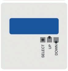
3. Safety

                                       CAUTION!
                                       ... indicates a potentially dangerous situation that can result in
                                       light injuries or damage to property or the environment, if not
                                       avoided.
                                                                                                             EN
                                       DANGER!
                                       ... identifies hazards caused by electrical power. Should the
                                       safety instructions not be observed, there is a risk of serious
                                       or fatal injury.

                                       WARNING!
                                       ... indicates a potentially dangerous situation that can result in
                                       burns, caused by hot surfaces or liquids, if not avoided.

                                       Information
                                       ... points out useful tips, recommendations and information for
                                       efficient and trouble-free operation.

                            3.2 Intended use
                            The A2G-100 is a multi-functional PID controller for differential pressure
                            or air flow control, specifically developed for the demands of the
                            air-conditioning and ventilation industry.

                            This PID controller enables a continuous pressure control or air flow
                            control for EC fans, variable air volume systems (VAV systems) or
                            ventilation flaps.

                            This instrument is not permitted to be used in hazardous areas!
40414622.01 03/2018 EN/DE

                            The instrument has been designed and built solely for the intended use
                            described here, and may only be used accordingly.

                            WIKA operating instructions model A2G-100                                    7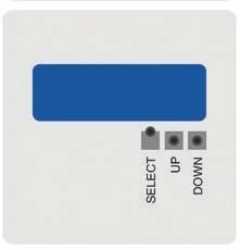
3. Safety

   The technical specifications contained in these operating instructions
   must be observed. Improper handling or operation of the instrument
   outside of its technical specifications requires the instrument to be taken
   out of service immediately and inspected by an authorised WIKA service
EN engineer.
     The manufacturer shall not be liable for claims of any type based on
     operation contrary to the intended use.

     3.3 Improper use

                WARNING!
                Injuries through improper use
                Improper use of the instrument can lead to hazardous
                situations and injuries.
                ▶▶ Refrain from unauthorised modifications to the instrument.
                ▶▶ Do not use the instrument within hazardous areas.
                ▶▶ Do not use the instrument with abrasive or viscous media.

     Any use beyond or different to the intended use is considered as
     improper use.

     Do not use this instrument in safety or emergency stop devices.

     3.4 Responsibility of the operator
     The instrument is used in the industrial sector. The operator is therefore
     responsible for legal obligations regarding safety at work.

     The safety instructions within these operating instructions, as well as the
     safety, accident prevention and environmental protection regulations for
     the application area must be maintained.
                                                                                   40414622.01 03/2018 EN/DE

     The operator is obliged to maintain the product label in a legible
     condition.

     8                                WIKA operating instructions model A2G-100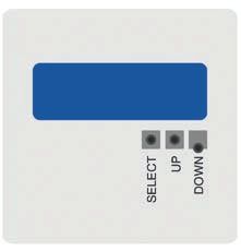
3. Safety

                            To ensure safe working on the instrument, the operating company must
                            ensure
                            ■■ that the operating personnel are regularly instructed in all topics
                               regarding work safety, first aid and environmental protection and know
                               the operating instructions and in particular, the safety instructions  EN
                               contained therein.
                            ■■ that the instrument is suitable for the particular application in
                               accordance with its intended use.
                            ■■ that personal protective equipment is available.

                            3.5 Personnel qualification

                                       WARNING!
                                       Risk of injury should qualification be insufficient
                                       Improper handling can result in considerable injury and
                                       damage to equipment.
                                       ▶▶ The activities described in these operating instructions
                                          may only be carried out by skilled personnel who have the
                                          qualifications described below.

                            Skilled electrical personnel
                            Skilled electrical personnel are understood to be personnel who, based
                            on their technical training, know-how and experience as well as their
                            knowledge of country-specific regulations, current standards and directives,
                            are capable of carrying out work on electrical systems and independently
                            recognising and avoiding potential hazards. The skilled electrical personnel
                            have been specifically trained for the work environment they are working
                            in and know the relevant standards and regulations. The skilled electrical
                            personnel must comply with current legal accident prevention regulations.

                            Operating personnel
                            The personnel trained by the operator are understood to be personnel
40414622.01 03/2018 EN/DE

                            who, based on their education, knowledge and experience, are capable
                            of carrying out the work described and independently recognising
                            potential hazards.

                            Special operating conditions require further appropriate knowledge, e.g.
                            of aggressive media.

                            WIKA operating instructions model A2G-100                                 9
3. Safety
3.6 Labelling, safety marks
Product label (example)
EN
Type: A2G-50
Range: -250 ... +250 Pa
Output: 0 ... 10 V / 4 ... 20 mA
Supply: DC 24 V / AC 24 V ±10 % < 1 W
Made in EU E-Nr. 66209848
Model
Measuring range
Output signal
Power supply
Serial number
Before mounting and commissioning the instrument, ensure
you read the operating instructions!
40414622.01 03/2018 EN/DE
10 WIKA operating instructions model A2G-1004. Transport, packaging and storage
4. Transport, packaging and storage
4.1 Transport
Check the instrument for any damage that may have been caused by
transport. EN
Obvious damage must be reported immediately.
CAUTION!
Damage through improper transport
With improper transport, a high level of damage to property
can occur.
▶▶ When unloading packed goods upon delivery as well as
during internal transport, proceed carefully and observe
the symbols on the packaging.
▶▶ With internal transport, observe the instructions in chapter
4.2 “Packaging and storage”.
If the instrument is transported from a cold into a warm environment, the
formation of condensation may result in instrument malfunction. Before
putting it back into operation, wait for the instrument temperature and the
room temperature to equalise.
4.2 Packaging and storage
Do not remove packaging until just before mounting.
Keep the packaging as it will provide optimum protection during transport
(e.g. change in installation site, sending for repair).
Permissible conditions at the place of storage:
■■ Storage temperature: -20 ... +70 °C
Avoid exposure to the following factors:
40414622.01 03/2018 EN/DE
■■Direct sunlight or proximity to hot objects
■■Mechanical vibration, mechanical shock (putting it down hard)
■■Soot, vapour, humidity, dust and corrosive gases
■■Hazardous environments, flammable atmospheres
WIKA operating instructions model A2G-100 114. Transport ... / 5. Commissioning, operation
Store the instrument in its original packaging in a location that fulfils the
conditions listed above. If the original packaging is not available, pack
and store the instrument as described below:
1. Wrap the instrument in an antistatic plastic film.
EN 2. Place the instrument, along with the shock-absorbent material, in the
packaging.
3. If stored for a prolonged period of time (more than 30 days), place a
bag containing a desiccant inside the packaging.
5. Commissioning, operation
Personnel: Skilled electrical personnel
Tools: Voltage tester, screwdriver
WARNING!
Physical injuries and damage to property and the
environment caused by hazardous media
Upon contact with hazardous media (e.g. oxygen, acetylene,
flammable or toxic substances), harmful media (e.g. corrosive,
toxic, carcinogenic, radioactive), and also with refrigeration
plants and compressors, there is a danger of physical injuries
and damage to property and the environment.
Should a failure occur, aggressive media with extremely high
temperature and under high pressure or vacuum may be
present at the instrument.
▶▶ For these media, in addition to all standard regulations,
the appropriate existing codes or regulations must also be
followed.
CAUTION!
40414622.01 03/2018 EN/DE
Damage to the instrument
When working on open electric circuits (printed circuit boards)
there is a risk of damaging sensitive electronic components
through electrostatic discharge.
▶▶ The correct use of grounded working surfaces and
personal armbands is required.
12 WIKA operating instructions model A2G-1005. Commissioning, operation
DANGER!
Danger to life caused by electric current
Upon contact with live parts, there is a direct danger to life.
▶▶ The instrument may only be installed and mounted by
skilled personnel. EN
▶▶ Operation using a defective power supply unit (e.g. short
circuit from the mains voltage to the output voltage) can
result in life-threatening voltages at the instrument!
1. Instrument fixing at the desired mounting location
(see chapter 5.1 “Instrument mounting”)
2. Opening the instrument cover, feeding the connection cable through
the cable gland and connecting the wires to the terminal block (see
chapter 5.2 “Electrical mounting”)
40414622.01 03/2018 EN/DE
WIKA operating instructions model A2G-100 135. Commissioning, operation
5.1 Instrument mounting
Screw the PID controller onto a suitable vertical surface and fix it
horizontally with the mounting screws delivered with the instrument.
EN 1. Select a mounting location (duct, wall, panel).
2. Remove the case cover and use the screw holes as a template.
3. Mount with suitable screws.
Instrument fixing
Instrument orientation
40414622.01 03/2018 EN/DE
14 WIKA operating instructions model A2G-1005. Commissioning, operation
Application-related connections
Static pressure Filter measurement/ Ventilator
1
measurement/control
2
control
3
measurement/control
EN
40414622.01 03/2018 EN/DE
WIKA operating instructions model A2G-100 155. Commissioning, operation
5.2 Electrical mounting
The instrument is designed to operate with safety extra-low voltage
(SELV). Operate the PID controller in the middle of the measuring range,
since deviations can occur at the range limits.
EN Operate the A2G-100 with a constant operating voltage (±0.2 V) and
ambient temperature. Prevent current/voltage spikes from switching the
power supply on or off.
For CE conformity, a properly grounded protective cable is required.
1. Unscrew the strain relief and feed the cable(s) through.
2. Connect the wires (see “Connection diagram”).
3. Tighten down the strain relief.
Connection diagram
■■ Output signal DC 0 ... 10 V
0 ... 10 V
not connected
V
24 V Power supply
AC/DC 24 V
GND
Pressure P Signal [U]
100 % 10.0 V
A
50 % 5.0 V
40414622.01 03/2018 EN/DE
0% 0.0 V
Time axis t [s]
Pressure P Signal [I]
100 % 20.0 mA
16 WIKA operating instructions model A2G-100Pressure P
V
Signal [U]
5. Commissioning, operation
100 % 10.0 V
■■ Output signal 4 ... 20 mA
50 %
not connected 5.0 V
4 ... 20 mA
A EN
24 V Power supply
AC/DC 24 V
0% GND 0.0 V
Time axis t [s]
Pressure P Signal [I]
100 % 20.0 mA
50 % 12.0 mA
0% 4.0 mA
Time axis t [s]
40414622.01 03/2018 EN/DE
WIKA operating instructions model A2G-100 175. Commissioning, operation
5.3 Output signal setting
The analogue output signal of the model A2G-100 PID controller can be
(Volumenstrom)
set between 0 ... 10 V and 4 ... 20 mA. The setting can be made via
Pressure
(Druck)
Flow
jumpers on the printed circuit board. 4-20 mA
EN Installing the jumpers Out
(Dark grey colour indicates the jumper placement)
1-10 V
1 2 3 4
Fitting the jumper to the slots, upper left/middle:
Output signal for the air flow: 4 ... 20 mA
Fitting the jumper to the slots, middle/below:
Output signal for the air flow: 0 ... 10 V
Fitting the jumper to the slots, upper right/middle:
Output signal for the differential pressure: 4 ... 20 mA
Fitting the jumper to the slots, right middle/below:
Output signal for the differential pressure: 0 ... 10 V
40414622.01 03/2018 EN/DE
Pressure
Air flow
(Volumenstrom)
Pressure
(Druck)
Flow
4 ... 20 mA
4-20 mA
Out
Out
1 ... 10 V
1-10 V
1 2 3 4
18 WIKA operating instructions model A2G-1005. Commissioning, operation
5.4 Zero point setting
5.4.1 Standard
Connect the voltage supply one hour before making the zero point
setting EN
1. Remove both hoses from the pressure connections ⊕ and ⊖.
2. Press the zero button until the red LED switches on.
3. Wait until the LED switches off again and install the hoses to the
pressure connections again.
4. In normal operation, we recommend that a zero point calibration is
carried out every 12 months.
5.4.2 Automatic zero point setting (option)
The automatic zero point setting makes the instrument maintenance-
free. The element corrects the zero point from time to time and thus
prevents a zero-point drift in the piezoresistive sensor element.
During the zero point setting the display and output value remains at the
last measured value. The automatic zero point setting takes 3 seconds
and is repeated every 10 minutes.
LED
Reset
40414622.01 03/2018 EN/DE
Reset LED
(Zurücksetzen)
WIKA operating instructions model A2G-100 196. Menu navigation
6. Menu navigation
6.1 Control variable 'pressure'
EN 1. Select function mode
Move the “SELECT” button in any direction for at least
2 seconds to activate the CONTROL UNIT mode. CONTROL UNIT
▶▶ “CONTROL UNIT” is displayed
PRESSURE
▶▶ Select control variable 'pressure'
2. Select unit for LC display and output signal: Pa, kPa, mbar, inWC
or mmWC
Move the “DOWN” button once, shortly
▶▶ “PRESS.UNIT” menu item is displayed PRESS.UNIT
Pa
Move the “SELECT” button once, shortly, in order to
activate the pressure unit selection. PRESS.UNIT
Pa
▶▶ Selection flashes
Use “UP” or “DOWN” to find the desired pressure unit.
▶▶ Selection is displayed PRESS.UNIT
40414622.01 03/2018 EN/DE
mbar
20 WIKA operating instructions model A2G-1006. Menu navigation
Move the “SELECT” button once, shortly, in order to
accept the selection. PRESS.UNIT
mbar
EN
3. Select maximum pressure range: 200 ... 2,500 Pa
Move the “DOWN” button once, shortly
▶▶ “P OUTPUT MAX” menu item is displayed P OUTPUT MAX
2000 Pa
Move the “SELECT” button once, shortly, in order to P OUTPUT MAX
activate the pressure range selection. 2000 Pa
▶▶ Selection flashes
Use “UP” or “DOWN” to find the desired range. P OUTPUT MAX
▶▶ Selection is displayed 600 Pa
Move the “SELECT” button once, shortly, in order to
accept the selection. P OUTPUT MAX
600 Pa
40414622.01 03/2018 EN/DE
WIKA operating instructions model A2G-100 216. Menu navigation
4. Select response time: between 1.0 … 20 s
Move the “DOWN” button once, shortly
▶▶ “RESPONSE TIME” menu item is displayed RESPONSE TIME
4s
EN
Move the “SELECT” button once, shortly, in order to RESPONSE TIME
activate the response time selection. 4s
▶▶ Selection flashes
Use “UP” or “DOWN” to find the desired response time. RESPONSE TIME
▶▶ Selection is displayed 14 s
Move the “SELECT” button once, shortly, in order to
accept the selection. RESPONSE TIME
14 s
40414622.01 03/2018 EN/DE
22 WIKA operating instructions model A2G-1006. Menu navigation
5. Select set point
Move the “DOWN” button once, shortly REF PRESSURE
▶▶ “REF PRESSURE” menu item is displayed 100 Pa
EN
Move the “SELECT” button once, shortly, in order to REF PRESSURE
activate the set point selection. 100 Pa
▶▶ Selection flashes
Use “UP” or “DOWN” to find the desired set point.
▶▶ Selection is displayed REF PRESSURE
160 Pa
Move the “SELECT” button once, shortly, in order to
accept the selection. REF PRESSURE
160 Pa
40414622.01 03/2018 EN/DE
WIKA operating instructions model A2G-100 236. Menu navigation
6. Select proportional band in relation to the specifications
Move the “DOWN” button once, shortly
▶▶ “P-VALUE” menu item is displayed P-VALUE
100
EN
Move the “SELECT” button once, shortly, in order to
activate the “P-VALUE” selection. P-VALUE
100
▶▶ Selection flashes
Use “UP” or “DOWN” to find the desired proportional
band. P-VALUE
▶▶ Selection is displayed 210
Move the “SELECT” button once, shortly, in order to
accept the selection. P-VALUE
210
40414622.01 03/2018 EN/DE
24 WIKA operating instructions model A2G-1006. Menu navigation
7. Select input damping
Move the “DOWN” button once, shortly I-VALUE
▶▶ “I-VALUE” menu item is displayed 4.0
EN
Move the “SELECT” button once, shortly, in order to I-VALUE
activate the input damping selection. 4.0
▶▶ Selection flashes
Use “UP” or “DOWN” to find the desired input damping. I-VALUE
▶▶ Selection is displayed 26.4
Move the “SELECT” button once, shortly, in order to
I-VALUE
accept the selection. 26.4
40414622.01 03/2018 EN/DE
WIKA operating instructions model A2G-100 256. Menu navigation
8. Select derivative time
Move the “DOWN” button once, shortly D-VALUE
▶▶ “D-VALUE” menu item is displayed 0.0
EN
Move the “SELECT” button once, shortly, in order to D-VALUE
activate the derivative time selection. 0.0
▶▶ Selection flashes
Use “UP” or “DOWN” to find the desired derivative
time. D-VALUE
▶▶ Selection is displayed
0.42
Move the “SELECT” button once, shortly, in order to
accept the selection. D-VALUE
0.42
9. Press the “SELECT” button in order to exit the
SELECT
menu.
40414622.01 03/2018 EN/DE
EXIT MENU
26 WIKA operating instructions model A2G-1006. Menu navigation
6.2 Control variable 'air flow'
1. Select function mode of the A2G-100
Move the “SELECT” button in any direction for at least
2 seconds to activate the CONTROL UNIT mode. CONTROL UNIT EN
▶▶ “CONTROL UNIT” is displayed
Flow
▶▶ Select control variable 'air flow'
2. Select function mode of the ventilator model
(from other manufacturer) MANUFACTURER
Fläkt Woods
Select “MANUFACTURER” to operate the A2G-100
with the ventilator model of a specific manufacturer.
Select “COMMON PROBE” to operate the A2G-100
with a model A2G-FM measuring probe (optionally
available as an accessory)
▶▶ “MANUFACTURER” / “COMMON PROBE” is
displayed
Move the “SELECT” button once, shortly, in order to
activate the selection of the ventilator manufacturer. MANUFACTURER
Fläkt Woods
▶▶ Selection flashes
Use “UP” or “DOWN” to find the desired ventilator
manufacturer. MANUFACTURER
Rosenberg
▶▶ The manufacturers are shown in a row
40414622.01 03/2018 EN/DE
WIKA operating instructions model A2G-100 276. Menu navigation
Move the “SELECT” button once, shortly, in order to
accept the displayed manufacturer. MANUFACTURER
Rosenberg
EN
3. Only for “Common probe”: Select unit
If “Common probe” is selected in step 2, only the unit (e.g. l/s) must be
set
Move the “DOWN” button once, shortly FORMULA UNIT
▶▶ “FORMULA UNIT” menu item is displayed 1/S
Move the “SELECT” button once, shortly, in order to FORMULA UNIT
activate the measuring unit selection. 1/S
▶▶ Selection flashes
Use “UP” or “DOWN” to find the desired unit.
▶▶ Selection is displayed FORMULA UNIT
m3/s
Move the “SELECT” button once, shortly, in order to
40414622.01 03/2018 EN/DE
accept the selection. FORMULA UNIT
m3/s
When using the model A2G-FM measuring probe,
activate the unit l/s.
28 WIKA operating instructions model A2G-1006. Menu navigation
4. Select K factor: Between 0.001 … 9999.000
If “MANUFACTURER” is selected in step 2, then only enter the
manufacturer and ventilator model. The K factor is automatically
determined by the measuring instrument.
EN
If a measuring probe or a different ventilator is used, then the K factor
must be entered.
Move the “DOWN” button once, shortly K-VALUE
▶▶ “K-VALUE” menu item is displayed 1,100
Move the “SELECT” button once, shortly, in order to K-VALUE
activate the “K-VALUE” selection. 1,100
▶▶ Selection flashes
Use “UP” or “DOWN” to enter the desired numbers.
Move the “SELECT” button to the left and right to K-VALUE
0061.130
select the decimal point.
▶▶ The “K-VALUE” is displayed
Move the “SELECT” button once, shortly, in order to
accept the selection. K-VALUE
0061.130
40414622.01 03/2018 EN/DE
WIKA operating instructions model A2G-100 296. Menu navigation
5. Select unit for LC display and output signal
Air flow: m3/s, m3/h, cfm, l/s
Flow velocity: m/s, f/m
EN Move the “DOWN” button once, shortly
▶▶ “FLOW UNIT” menu item is displayed FLOW UNIT
1/s
Move the “SELECT” button once, shortly, in order to FLOW UNIT
activate the unit selection. m3/s
▶▶ Selection flashes
Use “UP” or “DOWN” to find the desired unit. FLOW UNIT
▶▶ Selection is displayed cfm
Move the “SELECT” button once, shortly, in order to
accept the selection. FLOW UNIT
cfm
40414622.01 03/2018 EN/DE
30 WIKA operating instructions model A2G-1006. Menu navigation
6. Select maximum air flow
Move the “DOWN” button once, shortly
▶▶ “V OUTPUT MAX” menu item is displayed V OUTPUT MAX
50,000 m3/s
EN
Move the “SELECT” button once, shortly, in order to V OUTPUT MAX
activate the air flow selection. 50,000 m3/s
▶▶ Selection flashes
Use “UP” or “DOWN” to find the desired response time. V OUTPUT MAX
▶▶ Selection is displayed 30,000 m3/s
Move the “SELECT” button once, shortly, in order to
accept the selection. V OUTPUT MAX
30,000 m3/s
40414622.01 03/2018 EN/DE
WIKA operating instructions model A2G-100 316. Menu navigation
7. Select response time: between 1.0 … 20 s
Move the “DOWN” button once, shortly
▶▶ “RESPONSE TIME” menu item is displayed RESPONSE TIME
4s
EN
Move the “SELECT” button once, shortly, in order to RESPONSE TIME
activate the response time selection. 4s
▶▶ Selection flashes
Use “UP” or “DOWN” to find the desired response time. RESPONSE TIME
▶▶ Selection is displayed 14 s
Move the “SELECT” button once, shortly, in order to
RESPONSE TIME
accept the selection. 14 s
40414622.01 03/2018 EN/DE
32 WIKA operating instructions model A2G-1006. Menu navigation
8. Select set point
Move the “DOWN” button once, shortly REF FLOW
▶▶ “REF FLOW” is displayed 0.025 m3/s
EN
Move the “SELECT” button once, shortly, in order to REF FLOW
activate the set point selection. 0.025 m3/s
▶▶ Selection flashes
Use “UP” or “DOWN” to find the desired set point.
▶▶ Selection is displayed
REF FLOW
1,625 m3/s
Move the “SELECT” button once, shortly, in order to
accept the selection. REF FLOW
1,625 m3/s
40414622.01 03/2018 EN/DE
WIKA operating instructions model A2G-100 336. Menu navigation
9. Select proportional band in relation to the specifications
Move the “DOWN” button once, shortly
▶▶ “P-VALUE” menu item is displayed P-VALUE
100
EN
Move the “SELECT” button once, shortly, in order to
activate the “P-VALUE” selection. P-VALUE
100
▶▶ Selection flashes
Use “UP” or “DOWN” to find the desired proportional
band. P-VALUE
▶▶ Selection is displayed 210
Move the “SELECT” button once, shortly, in order to
accept the selection. P-VALUE
210
40414622.01 03/2018 EN/DE
34 WIKA operating instructions model A2G-1006. Menu navigation
10. Select input damping
Move the “DOWN” button once, shortly I-VALUE
▶▶ “I-VALUE” menu item is displayed 4.0
EN
Move the “SELECT” button once, shortly, in order to I-VALUE
activate the input damping selection. 4.0
▶▶ Selection flashes
Use “UP” or “DOWN” to find the desired input damping.
▶▶ Selection is displayed I-VALUE
26.4
Move the “SELECT” button once, shortly, in order to
accept the selection. I-VALUE
26.4
40414622.01 03/2018 EN/DE
WIKA operating instructions model A2G-100 356. Menu navigation
11. Select derivative time
Move the “DOWN” button once, shortly D-VALUE
▶▶ “D-VALUE” menu item is displayed 0.0
EN
Move the “SELECT” button once, shortly, in order to D-VALUE
activate the derivative time selection. 0.0
▶▶ Selection flashes
Use “UP” or “DOWN” to find the desired derivative
time. D-VALUE
0.42
▶▶ Selection is displayed
Move the “SELECT” button once, shortly, in order to
accept the selection. D-VALUE
0.42
12. Press the “SELECT” button in order to exit the
SELECT
menu. EXIT MENU
40414622.01 03/2018 EN/DE
36 WIKA operating instructions model A2G-1007. Maintenance, cleaning and recalibration
7. Maintenance, cleaning and recalibration
Personnel: Skilled electrical personnel
Tools: Voltage tester, screwdriver
EN
For contact details see chapter 1 “General information” or the
back page of the operating instructions.
7.1 Maintenance
This instrument is maintenance-free and offers long service life provided
it is handled and operated properly.
Repairs must only be carried out by the manufacturer or appropriately
qualified skilled personnel.
7.2 Cleaning
CAUTION!
Physical injuries and damage to property and the
environment
Improper cleaning may lead to physical injuries and damage
to property and the environment. Residual media in the
dismounted instrument can result in a risk to persons, the
environment and equipment.
▶▶ Carry out the cleaning process as described below.
1. Before cleaning, correctly disconnect the instrument from the pressure
supply, switch it off and disconnect it from the mains.
2. Use the requisite protective equipment.
40414622.01 03/2018 EN/DE
3. Clean the instrument with a moist cloth (soapy water).
Electrical connections must not come into contact with moisture!
WIKA operating instructions model A2G-100 377. Maintenance, cleaning ... / 8. Dismounting ...
CAUTION!
Damage to the instrument
Improper cleaning may lead to damage to the instrument!
▶▶ Do not use any aggressive cleaning agents.
EN ▶▶ Do not use any hard or pointed objects for cleaning.
4. Wash or clean the dismounted instrument, in order to protect persons
and the environment from exposure to residual media.
7.3 Recalibration
DKD/DAkkS certificate - official certificates:
We recommend that the instrument is regularly recalibrated by the
manufacturer, with time intervals of approx. 12 months. The basic
settings will be corrected if necessary.
8. Dismounting, return and disposal
Personnel: Skilled electrical personnel
Tools: Voltage tester, screwdriver
WARNING!
Physical injuries and damage to property and the
environment through residual media
Residual media in the dismounted instrument can result in a
risk to persons, the environment and equipment.
▶▶ Observe the information in the material safety data sheet
for the corresponding medium.
▶▶ Wash or clean the dismounted instrument, in order to
protect persons and the environment from exposure to
residual media.
40414622.01 03/2018 EN/DE
38 WIKA operating instructions model A2G-1008. Dismounting, return and disposal
8.1 Dismounting
WARNING!
Physical injuries and damage to property and the
environment through residual media
Upon contact with hazardous media (e.g. oxygen, acetylene,
EN
flammable or toxic substances), harmful media (e.g. corrosive,
toxic, carcinogenic, radioactive), and also with refrigeration
plants and compressors, there is a danger of physical injuries
and damage to property and the environment.
▶▶ Before storage of the dismounted instrument (following
use) wash or clean it, in order to protect persons and the
environment from exposure to residual media.
▶▶ Observe the information in the material safety data sheet
for the corresponding medium.
WARNING!
Risk of burns
During dismounting there is a risk of dangerously hot media
escaping.
▶▶ Let the instrument cool down sufficiently before
dismounting it!
DANGER!
Danger to life caused by electric current
Upon contact with live parts, there is a direct danger to life.
▶▶ The dismounting of the instrument may only be carried out
by skilled personnel.
▶▶ Remove the instrument once the system has been isolated
from power sources.
WARNING!
40414622.01 03/2018 EN/DE
Physical injury
When dismounting, there is a danger from aggressive media
and high pressures.
▶▶ Observe the information in the material safety data sheet
for the corresponding medium.
▶▶ Dismount the instrument when there is no pressure.
WIKA operating instructions model A2G-100 398. Dismounting, return and disposal
8.2 Return
Strictly observe the following when shipping the instrument:
All instruments delivered to WIKA must be free from any kind of
hazardous substances (acids, bases, solutions, etc.) and must therefore
EN be cleaned before being returned.
WARNING!
Physical injuries and damage to property and the
environment through residual media
Residual media in the dismounted instrument can result in a
risk to persons, the environment and equipment.
▶▶ With hazardous substances, include the material safety
data sheet for the corresponding medium.
▶▶ Clean the instrument, see chapter 7.2 “Cleaning”.
When returning the instrument, use the original packaging or a suitable
transport packaging.
To avoid damage:
1. Wrap the instrument in an antistatic plastic film.
2. Place the instrument, along with the shock-absorbent material, in the
packaging.
Place shock-absorbent material evenly on all sides of the transport
packaging.
3. If possible, place a bag, containing a desiccant, inside the packaging.
4. Label the shipment as transport of a highly sensitive measuring
instrument.
Information on returns can be found under the heading
“Service” on our local website.
40414622.01 03/2018 EN/DE
8.3 Disposal
Incorrect disposal can put the environment at risk.
Dispose of instrument components and packaging materials in an
environmentally compatible way and in accordance with the country-
specific waste disposal regulations.
40 WIKA operating instructions model A2G-1009. Specifications
9. Specifications
PID controller, model A2G-100
Measuring element Piezo measuring cell
Measuring range 0 … 2,500 Pa and 0 … 7,000 Pa EN
Max. pressure 25 kPa
Accuracy 0 ... 2,500 Pa = pressure < 125 Pa = ±2 Pa + 1 %
Pressure > 125 Pa = ±1 Pa + 1 %
0 ... 7,000 Pa = pressure < 125 Pa = ±2 Pa + 1.5 %
Pressure > 125 Pa = ±1 Pa + 1.5 %
all data refer to the current measured value (of the
measured pressure)
Units (selectable on display)
■■ Pressure PA, kPa, mbar, inWC, mmWC, psi
■■ Air flow m3/s, m3/h, cfm, l/s
■■ Rate m/s, ft/min
Process connection Connecting nozzle (ABS), lower mount, for hoses
with inner diameter 4 or 6 mm
LC display Line 1: Direction of the monitoring output
Line 2: Pressure or air flow display, can be set via
the menu
Power supply UB AC 24 V or DC 24 V ±10 %
Electrical connection Cable gland M20
4 spring-clip terminals, max. 1.5 mm2
Output signal ■■ DC 0 ... 10 V, 3-wire
■■ 4 ... 20 mA, 3-wire
Case Plastic (ABS), cover PVC
Permissible temperatures
■■ Ambient temperature -20 ... +70 °C
■■ Medium temperature -10 ... +50 °C, version with automatic zero point
setting: -5 ... +50 °C
40414622.01 03/2018 EN/DE
Relative humidity 0 ... 95 % r. h.
Ingress protection IP54
Weight 150 g
For further specifications see WIKA data sheet SP 69.11 and the order
documentation.
WIKA operating instructions model A2G-100 41EN
40414622.01 03/2018 EN/DE
42 WIKA operating instructions model A2G-100Inhalt
Inhalt
1. Allgemeines 44 DE
2. Aufbau und Funktion 45
3. Sicherheit 46
4. Transport, Verpackung und Lagerung 51
5. Inbetriebnahme, Betrieb 52
6. Menüführung 60
7. Wartung, Reinigung und Rekalibrierung 77
8. Demontage, Rücksendung und Entsorgung 78
9. Technische Daten 81
Konformitätserklärungen finden Sie online unter www.wika.de.
40414622.01 03/2018 EN/DE
WIKA Betriebsanleitung Typ A2G-100 431. Allgemeines
1. Allgemeines
■■ Das in der Betriebsanleitung beschriebene PID-Regelgerät wird nach
dem aktuellen Stand der Technik gefertigt. Alle Komponenten unterlie-
gen während der Fertigung strengen Qualitäts- und Umweltkriterien.
Unsere Managementsysteme sind nach ISO 9001 und ISO 14001
zertifiziert.
DE ■■ Diese Betriebsanleitung gibt wichtige Hinweise zum Umgang mit dem
Gerät. Voraussetzung für sicheres Arbeiten ist die Einhaltung aller
angegebenen Sicherheitshinweise und Handlungsanweisungen.
■■ Die für den Einsatzbereich des Gerätes geltenden örtlichen Unfall-
verhütungsvorschriften und allgemeinen Sicherheitsbestimmungen
einhalten.
■■ Die Betriebsanleitung ist Produktbestandteil und muss in unmittel-
barer Nähe des Gerätes für das Fachpersonal jederzeit zugänglich
aufbewahrt werden. Betriebsanleitung an nachfolgende Benutzer
oder Besitzer des Gerätes weitergeben.
■■ Das Fachpersonal muss die Betriebsanleitung vor Beginn aller Arbei-
ten sorgfältig durchgelesen und verstanden haben.
■■ Es gelten die allgemeinen Geschäftsbedingungen in den Verkaufsun-
terlagen.
■■ Technische Änderungen vorbehalten.
■■ Weitere Informationen:
- Internet-Adresse: www.wika.de / www.wika.com
www.air2guide.com
- Zugehöriges Datenblatt: SP 69.11
40414622.01 03/2018 EN/DE
44 WIKA Betriebsanleitung Typ A2G-1002. Aufbau und Funktion
2. Aufbau und Funktion
2.1 Überblick
DE
Gehäuse
LC-Display
Kabelverschraubung M16
Anschlussstutzen (ABS), für Schläuche mit Innendurchmesser 4 oder 6 mm
2.2 Beschreibung
Das PID-Regelgerät Typ A2G-100 dient zur Regelung von Differenzdrü-
cken oder Volumenströmen in der Luft- und Klimatechnik.
Der 0 ... 10 V- oder 4 ... 20 mA-Kontrollausgang wird als Steuersignal
direkt an den EC-Lüftungsventilator oder Frequenzumrichter (FU)
angeschlossen. Sein zweizeiliges LC-Display zeigt die Richtung des
Regelausgangs und den aktuellen Messwert zur gleichen Zeit. Als
analoge elektrische Ausgangssignale stehen 0 ... 10 V oder 4 ... 20 mA
40414622.01 03/2018 EN/DE
zu Verfügung, wobei die Einstellung durch den Nutzer direkt mit Jumper
im Gerät vorgenommen werden kann.
WIKA Betriebsanleitung Typ A2G-100 452. Aufbau und Funktion / 3. Sicherheit
2.3 Abmessungen in mm
DE
40405589.02
2.4 Lieferumfang
■■ PID-Regelgerät
■■ 2 Befestigungsschrauben
■■ 2 Kanalanschlussnippel (Option)
■■ 2 x 2 m PVC-Messschlauch (Option)
Lieferumfang mit dem Lieferschein abgleichen.
3. Sicherheit
3.1 Symbolerklärung
40414622.01 03/2018 EN/DE
WARNUNG!
... weist auf eine möglicherweise gefährliche Situation hin, die
zum Tod oder zu schweren Verletzungen führen kann, wenn
sie nicht gemieden wird.
46 WIKA Betriebsanleitung Typ A2G-1003. Sicherheit
VORSICHT!
... weist auf eine möglicherweise gefährliche Situation hin, die
zu geringfügigen oder leichten Verletzungen bzw. Sach- und
Umweltschäden führen kann, wenn sie nicht gemieden wird.
GEFAHR!
... kennzeichnet Gefährdungen durch elektrischen Strom. Bei
Nichtbeachtung der Sicherheitshinweise besteht die Gefahr DE
schwerer oder tödlicher Verletzungen.
WARNUNG!
... weist auf eine möglicherweise gefährliche Situation hin, die
durch heiße Oberflächen oder Flüssigkeiten zu Verbrennun-
gen führen kann, wenn sie nicht gemieden wird.
Information
... hebt nützliche Tipps und Empfehlungen sowie Informatio-
nen für einen effizienten und störungsfreien Betrieb hervor.
3.2 Bestimmungsgemäße Verwendung
Der A2G-100 ist ein multifunktionales PID-Regelgerät zur Differenz-
druck- oder Volumenstromregelung speziell entwickelt für die Ansprüche
der Luft- und Klimatechnik.
Dieses PID-Regelgerät ermöglicht eine konstante Druckregelung oder
Volumenstromregelung von EC-Ventilatoren, variablen Volumenstrom-
systemen (VVS-Anlagen) oder Lüftungsklappen.
Dieses Gerät ist nicht für den Einsatz in explosionsgefährdeten Berei-
40414622.01 03/2018 EN/DE
chen zugelassen!
Das Gerät ist ausschließlich für den hier beschriebenen bestimmungs-
gemäßen Verwendungszweck konzipiert und konstruiert und darf nur
dementsprechend verwendet werden.
WIKA Betriebsanleitung Typ A2G-100 473. Sicherheit
Die technischen Spezifikationen in dieser Betriebsanleitung sind
einzuhalten. Eine unsachgemäße Handhabung oder ein Betreiben des
Gerätes außerhalb der technischen Spezifikationen macht die sofortige
Stilllegung und Überprüfung durch einen autorisierten WIKA-Servicemit-
arbeiter erforderlich.
Ansprüche jeglicher Art aufgrund von nicht bestimmungsgemäßer
Verwendung sind ausgeschlossen.
DE
3.3 Fehlgebrauch
WARNUNG!
Verletzungen durch Fehlgebrauch
Fehlgebrauch des Gerätes kann zu gefährlichen Situationen
und Verletzungen führen.
▶▶ Eigenmächtige Umbauten am Gerät unterlassen.
▶▶ Gerät nicht in explosionsgefährdeten Bereichen einsetzen.
▶▶ Gerät nicht für abrasive und viskose Messstoffe verwenden.
Jede über die bestimmungsgemäße Verwendung hinausgehende oder
andersartige Benutzung gilt als Fehlgebrauch.
Dieses Gerät nicht in Sicherheits- oder in Not-Aus-Einrichtungen benut-
zen.
3.4 Verantwortung des Betreibers
Das Gerät wird im gewerblichen Bereich eingesetzt. Der Betreiber unter-
liegt daher den gesetzlichen Pflichten zur Arbeitssicherheit.
Die Sicherheitshinweise dieser Betriebsanleitung, sowie die für den
Einsatzbereich des Gerätes gültigen Sicherheits-, Unfallverhütungs- und
Umweltschutzvorschriften einhalten.
40414622.01 03/2018 EN/DE
Der Betreiber ist verpflichtet das Typenschild lesbar zu halten.
48 WIKA Betriebsanleitung Typ A2G-1003. Sicherheit
Für ein sicheres Arbeiten am Gerät muss der Betreiber sicherstellen,
■■ dass das Bedienpersonal regelmäßig in allen zutreffenden Fragen
von Arbeitssicherheit, Erste Hilfe und Umweltschutz unterwiesen wird,
sowie die Betriebsanleitung und insbesondere die darin enthaltenen
Sicherheitshinweise kennt.
■■ dass das Gerät gemäß der bestimmungsgemäßen Verwendung für
den Anwendungsfall geeignet ist.
■■ dass die persönliche Schutzausrüstung verfügbar ist.
DE
3.5 Personalqualifikation
WARNUNG!
Verletzungsgefahr bei unzureichender Qualifikation
Unsachgemäßer Umgang kann zu erheblichen Personen-
und Sachschäden führen.
▶▶ Die in dieser Betriebsanleitung beschriebenen Tätigkei-
ten nur durch Fachpersonal nachfolgend beschriebener
Qualifikation durchführen lassen.
Elektrofachpersonal
Das Elektrofachpersonal ist aufgrund seiner fachlichen Ausbildung,
Kenntnisse und Erfahrungen sowie Kenntnis der landesspezifischen
Vorschriften, geltenden Normen und Richtlinien in der Lage, Arbeiten an
elektrischen Anlagen auszuführen und mögliche Gefahren selbstständig
zu erkennen und zu vermeiden. Das Elektrofachpersonal ist speziell
für das Arbeitsumfeld, in dem es tätig ist, ausgebildet und kennt die
relevanten Normen und Bestimmungen. Das Elektrofachpersonal muss
die Bestimmungen der geltenden gesetzlichen Vorschriften zur Unfall-
verhütung erfüllen.
Bedienpersonal
40414622.01 03/2018 EN/DE
Das vom Betreiber geschulte Personal ist aufgrund seiner Bildung,
Kenntnisse und Erfahrungen in der Lage, die beschriebenen Arbeiten
auszuführen und mögliche Gefahren selbstständig zu erkennen.
Spezielle Einsatzbedingungen verlangen weiteres entsprechendes
Wissen, z. B. über aggressive Medien.
WIKA Betriebsanleitung Typ A2G-100 493. Sicherheit
3.6 Beschilderung, Sicherheitskennzeichnungen
Typenschild (Beispiel)
DE Type: A2G-50
Range: -250 ... +250 Pa
Output: 0 ... 10 V / 4 ... 20 mA
Supply: DC 24 V / AC 24 V ±10 % < 1 W
Made in EU E-Nr. 66209848
Typ
Messbereich
Ausgangssignal
Hilfsenergie
Seriennummer
Vor Montage und Inbetriebnahme des Gerätes unbedingt die
Betriebsanleitung lesen!
40414622.01 03/2018 EN/DE
50 WIKA Betriebsanleitung Typ A2G-1004. Transport, Verpackung und Lagerung
4. Transport, Verpackung und Lagerung
4.1 Transport
Gerät auf eventuell vorhandene Transportschäden untersuchen.
Offensichtliche Schäden unverzüglich mitteilen.
VORSICHT!
Beschädigungen durch unsachgemäßen Transport DE
Bei unsachgemäßem Transport können Sachschäden in
erheblicher Höhe entstehen.
▶▶ Beim Abladen der Packstücke bei Anlieferung sowie
innerbetrieblichem Transport vorsichtig vorgehen und die
Symbole auf der Verpackung beachten.
▶▶ Bei innerbetrieblichem Transport die Hinweise unter
Kapitel 4.2 „Verpackung und Lagerung“ beachten.
Wird das Gerät von einer kalten in eine warme Umgebung transportiert,
so kann durch Kondensatbildung eine Störung der Gerätefunktion eintre-
ten. Vor einer erneuten Inbetriebnahme die Angleichung der Gerätetem-
peratur an die Raumtemperatur abwarten.
4.2 Verpackung und Lagerung
Verpackung erst unmittelbar vor der Montage entfernen.
Die Verpackung aufbewahren, denn diese bietet bei einem Transport
einen optimalen Schutz (z. B. wechselnder Einbauort, Reparatursen-
dung).
Zulässige Bedingungen am Lagerort:
■■ Lagertemperatur: -20 ... +70 °C
Folgende Einflüsse vermeiden:
40414622.01 03/2018 EN/DE
■■Direktes Sonnenlicht oder Nähe zu heißen Gegenständen
■■Mechanische Vibration, mechanischer Schock (hartes Aufstellen)
■■Ruß, Dampf, Feuchtigkeit, Staub und korrosive Gase
■■Explosionsgefährdete Umgebung, entzündliche Atmosphären
WIKA Betriebsanleitung Typ A2G-100 514. Transport ... / 5. Inbetriebnahme, Betrieb
Das Gerät in der Originalverpackung an einem Ort lagern, der die oben
gelisteten Bedingungen erfüllt. Wenn die Originalverpackung nicht
vorhanden ist, dann das Gerät wie folgt verpacken und lagern:
1. Das Gerät in eine antistatische Plastikfolie einhüllen.
2. Das Gerät mit dem Dämmmaterial in der Verpackung platzieren.
3. Bei längerer Einlagerung (mehr als 30 Tage) einen Beutel mit Trock-
nungsmittel der Verpackung beilegen.
DE
5. Inbetriebnahme, Betrieb
Personal: Elektrofachpersonal
Werkzeuge: Spannungsprüfer, Schraubendreher
WARNUNG!
Körperverletzungen, Sach- und Umweltschäden durch
gefährliche Messstoffe
Bei Kontakt mit gefährlichen Messstoffen (z. B. Sauerstoff,
Acetylen, brennbaren oder giftigen Stoffen), gesundheitsge-
fährdenden Messstoffen (z. B. ätzend, giftig, krebserregend,
radioaktiv) sowie bei Kälteanlagen, Kompressoren besteht die
Gefahr von Körperverletzungen, Sach- und Umweltschäden.
Am Gerät können im Fehlerfall aggressive Medien mit extremer
Temperatur und unter hohem Druck oder Vakuum anliegen.
▶▶ Bei diesen Messstoffen müssen über die gesamten
allgemeinen Regeln hinaus die einschlägigen Vorschriften
beachtet werden.
VORSICHT!
Beschädigung des Gerätes
40414622.01 03/2018 EN/DE
Bei Arbeiten mit offenen Schaltkreisen (Leiterplatten) besteht
die Gefahr empfindliche elektronische Bauteile durch elektro-
statische Entladung zu beschädigen.
▶▶ Die ordnungsgemäße Verwendung geerdeter Arbeitsflä-
chen und persönlicher Armbänder ist erforderlich.
52 WIKA Betriebsanleitung Typ A2G-1005. Inbetriebnahme, Betrieb
GEFAHR!
Lebensgefahr durch elektrischen Strom
Bei Berührung mit spannungsführenden Teilen besteht unmit-
telbare Lebensgefahr.
▶▶ Einbau und Montage des Gerätes dürfen nur durch
Fachpersonal erfolgen.
▶▶ Bei Betrieb mit einem defekten Netzgerät (z. B.
Kurzschluss von Netzspannung zur Ausgangsspannung)
können am Gerät lebensgefährliche Spannungen auftre- DE
ten!
1. Gerätebefestigung an der gewünschten Montagestelle
(siehe Kapitel 5.1 „Gerätemontage“)
2. Öffnen des Gerätedeckels, Durchführung des Anschlusskabels
durch die Kabelverschraubung und Anschluss der Drähte an den
Klemmenblock (siehe Kapitel 5.2 „Elektrische Montage“)
40414622.01 03/2018 EN/DE
WIKA Betriebsanleitung Typ A2G-100 535. Inbetriebnahme, Betrieb
5.1 Gerätemontage
Das PID-Regelgerät auf einer geeigneten vertikalen Fläche aufschrau-
ben und waagerecht mit den beiliegenden Befestigungsschrauben
befestigen.
1. Montageort wählen (Kanal, Wand, Panel).
2. Gehäusedeckel entfernen und die Schraubenlöcher als Schablone
verwenden.
DE 3. Mit geeigneten Schrauben montieren.
Gerätebefestigung
Geräteausrichtung
40414622.01 03/2018 EN/DE
54 WIKA Betriebsanleitung Typ A2G-1005. Inbetriebnahme, Betrieb
Anwendungsbezogene Anschlüsse
Statische Filtermessung/ Ventilatormessung/
1
Druckmessung/-regelung
2
-regelung
3
-regelung
DE
40414622.01 03/2018 EN/DE
WIKA Betriebsanleitung Typ A2G-100 555. Inbetriebnahme, Betrieb
5.2 Elektrische Montage
Das Gerät ist für den Betrieb an Schutzkleinspannung (SELV) ausgelegt.
Das PID-Regelgerät in der Messbereichsmitte betreiben, da an den
Messbereichsendpunkten erhöhte Abweichungen auftreten können.
A2G-100 bei einer konstanten Betriebsspannung (±0,2 V) und
Umgebungstemperatur betreiben. Strom-/Spannungsspitzen beim Ein-/
Ausschalten der Hilfsenergie bauseitig vermeiden.
DE Für die CE-Konformität ist ein ordnungsgemäß geerdetes Schutzkabel
erforderlich.
1. Die Zugentlastung abschrauben und das (die) Kabel durchführen.
2. Die Drähte anschließen (siehe „Anschlussschema“).
3. Zugentlastung festziehen.
Anschlussschema
■■ Ausgangssignal DC 0 ... 10 V
0 ... 10 V
nicht angeschlossen
V
24 V Hilfsenergie
GND Ausgangssignal
AC/DC 24 V
A2G-25 Volumenstrommessumformer
Signalkurve [U] Signal-Ausgang [U] Spannung 0…10 V DC
Druck P Signal [U]
100 % 10.0 V
A
50 % 5.0 V
40414622.01 03/2018 EN/DE
0% 0.0 V
Zeitachse t [s]
Signalkurve [I] Signal-Ausgang [I] Strom 4…20 mA
Druck P Signal [I]
100 % 20.0 mA
56 WIKA Betriebsanleitung Typ A2G-100Signalkurve [U] Signal-Ausgang [U] Spannung 0…10 V DC
Druck P
V
Signal [U]
5. Inbetriebnahme, Betrieb
100 % 10.0 V
■■ Ausgangssignal 4 ... 20 mA
50 %
nicht angeschlossen 5.0 V
4 ... 20 mA
24 V Hilfsenergie
A
AC/DC 24 V
0% GND 0.0 V
Zeitachse t [s]
Signalkurve [I] Signal-Ausgang [I] Strom 4…20 mA
DE
Druck P Signal [I]
100 % 20.0 mA
50 % 12.0 mA
0% 4.0 mA
Zeitachse t [s]
Erstellt: Philipp Kottmann am: 29.04.2015 Datei: Signal_A2G-25.docx Seite 2 von 1
MANOMETER AG T +41(0)41 919 72 72
Industriestrasse 11 F +41(0)41 919 72 73
CH-6285 Hitzkirch E-Mail info@manometer.ch
40414622.01 03/2018 EN/DE
WIKA Betriebsanleitung Typ A2G-100 575. Inbetriebnahme, Betrieb
5.3 Einstellen des Ausgangssignals
Das analoge Ausgangssignal des PID-Regelgerätes Typ A2G-100 ist
(Volumenstrom)
zwischen 0 ... 10 V und 4 ... 20 mA einstellbar. Die Einstellung kann über
Pressure
(Druck)
Flow
Brücken auf der Platine vorgenommen werden. 4-20 mA
Installation der Brücken Out
(Farbe dunkelgrau signalisiert die Brückenplatzierung)
1-10 V
1 2 3 4
DE
Montage der Brücke auf den Steckplätzen links oben/Mitte:
Ausgangssignal für den Volumenstrom: 4 ... 20 mA
Montage der Brücke auf den Steckplätzen links Mitte/unten:
Ausgangssignal für den Volumenstrom: 0 ... 10 V
Montage der Brücke auf den Steckplätzen rechts oben/Mitte:
Ausgangssignal für den Differenzdruck: 4 ... 20 mA
Montage der Brücke auf den Steckplätzen rechts Mitte/unten:
Ausgangssignal für den Differenzdruck: 0 ... 10 V
Volumenstrom
40414622.01 03/2018 EN/DE
(Volumenstrom)
Druck
Pressure
(Druck)
Flow
4 ... 20 mA
4-20 mA
Out
Out
1 ... 10 V
1-10 V
1 2 3 4
58 WIKA Betriebsanleitung Typ A2G-1005. Inbetriebnahme, Betrieb
5.4 Nullpunkteinstellung
5.4.1 Standard
Die Spannungsversorgung eine Stunde vor der Nullpunkteinstel-
lung anschließen!
1. Beide Schläuche von den Druckanschlüssen ⊕ und ⊖ lösen.
2. Null-Taste drücken bis sich die rote LED einschaltet.
3. Warten bis sich die LED wieder ausschaltet und anschließend die
Schläuche wieder an die Druckanschlüsse installieren. DE
4. Bei normalem Betrieb ist es empfehlenswert, die Nullpunktkalibrierung
alle 12 Monate vorzunehmen.
5.4.2 Automatische Nullpunkteinstellung (Option)
Die automatische Nullpunkteinstellung macht das Gerät wartungsfrei.
Das Element korrigiert von Zeit zu Zeit den Nullpunkt und verhindert
somit einen Nullpunktdrift des piezoresistiven Sensorelements.
Während der Nullpunkteinstellung bleibt der Anzeige- und Ausgangswert
beim letzten gemessenen Wert stehen. Die automatische Nullpunktein-
stellung dauert 3 Sekunden und wird alle 10 Minuten wiederholt.
LED
Reset
(Zurücksetzen)
40414622.01 03/2018 EN/DE
Reset LED
(Zurücksetzen)
WIKA Betriebsanleitung Typ A2G-100 596. Menüführung
6. Menüführung
6.1 Regelgröße Druck
1. Funktionsmodus wählen
Die Taste „SELECT“ für mindestens 2 Sekunden
in eine beliebige Richtung bewegen, um den CONTROL UNIT
PRESSURE
DE CONTROL UNIT-Modus zu aktivieren.
▶▶ „CONTROL UNIT“ erscheint
▶▶ Regelgröße Druck wählen
2. Einheit für LC-Display und Ausgangssignal wählen:
Pa, kPa, mbar, inWC oder mmWC
Taste „DOWN“ einmal kurz bewegen
▶▶ Menüpunkt „PRESS.UNIT“ erscheint PRESS.UNIT
Pa
Taste „SELECT“ einmal kurz bewegen, um die
Auswahl der Druckeinheit zu aktivieren. PRESS.UNIT
Pa
▶▶ Auswahl blinkt
„UP“ oder „DOWN“ verwenden, um die gewünschte
Druckeinheit zu finden.
40414622.01 03/2018 EN/DE
PRESS.UNIT
▶▶ Auswahl wird angezeigt mbar
60 WIKA Betriebsanleitung Typ A2G-1006. Menüführung
Taste „SELECT“ einmal kurz bewegen, um die
Auswahl zu bestätigen. PRESS.UNIT
mbar
3. Maximalen Druckbereich wählen: 200 ... 2.500 Pa
DE
Taste „DOWN“ einmal kurz bewegen
▶▶ Menüpunkt „P OUTPUT MAX“ erscheint P OUTPUT MAX
2000 Pa
Taste „SELECT“ einmal kurz bewegen, um die P OUTPUT MAX
Auswahl des Druckbereiches zu aktivieren. 2000 Pa
▶▶ Auswahl blinkt
„UP“ oder „DOWN“ verwenden, um den gewünschten
P OUTPUT MAX
Bereich zu finden. 600 Pa
▶▶ Auswahl wird angezeigt
Taste „SELECT“ einmal kurz bewegen, um die
Auswahl zu bestätigen. P OUTPUT MAX
600 Pa
40414622.01 03/2018 EN/DE
WIKA Betriebsanleitung Typ A2G-100 616. Menüführung
4. Ansprechzeit wählen: zwischen 1,0 … 20 s
Taste „DOWN“ einmal kurz bewegen
▶▶ Menüpunkt „RESPONSETIME“ erscheint RESPONSE TIME
4s
DE
Taste „SELECT“ einmal kurz bewegen, um die RESPONSE TIME
Auswahl der Ansprechzeit zu aktivieren. 4s
▶▶ Auswahl blinkt
„UP“ oder „DOWN“ verwenden, um die gewünschte RESPONSE TIME
Ansprechzeit zu finden. 14 s
▶▶ Auswahl wird angezeigt
Taste „SELECT“ einmal kurz bewegen, um die
Auswahl zu bestätigen. RESPONSE TIME
14 s
40414622.01 03/2018 EN/DE
62 WIKA Betriebsanleitung Typ A2G-100You can also read