460MCBM-NNA1 Protocol Gateway - Product User Guide Firmware Version 8.7.22 - Real Time Automation
←
→
Page content transcription
If your browser does not render page correctly, please read the page content below
460MCBM-NNA1
                             Protocol Gateway
                                 Product User Guide
                                 Firmware Version 8.7.22

Real Time Automation, Inc.   1               1-800-249-1612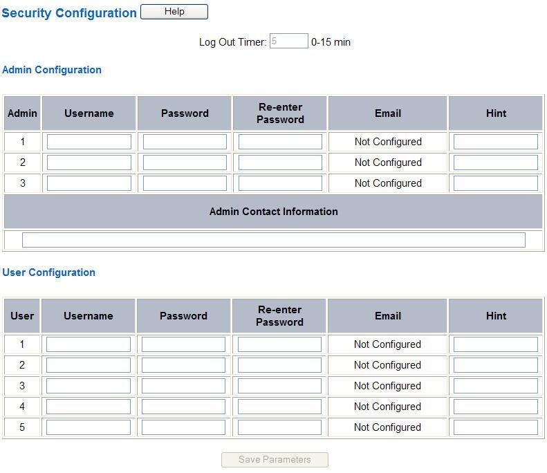
Trademarks

CompactLogix, ControlLogix, & PLC-5 are registered trademarks of Rockwell Automation, Inc. EtherNet/IP is a trademark of the ODVA.
MicroLogix, RSLogix 500, and SLC are trademarks of Rockwell Automation, Inc. Microsoft, Windows, and Internet Explorer are registered
trademarks of Microsoft Corporation. BACnet® is a registered trademark of American Society of Heating, Refrigerating and Air-Conditioning
Engineers (ASHRAE). All other trademarks and registered trademarks are the property of their holders.

Limited Warranty

Real Time Automation, Inc. warrants that this product is free from defects and functions properly.

EXCEPT AS SPECIFICALLY SET FORTH ABOVE, REAL TIME AUTOMATION, INC. DISCLAIMS ALL OTHER WARRANTIES, BOTH
EXPRESSED AND IMPLIED, INCLUDING BUT NOT LIMITED TO IMPLIED WARRANTIES OF MERCHANTABILITY OR FITNESS FOR A
PARTICULAR APPLICATION. THIS LIMITED WARRANTY GIVES YOU SPECIFIC LEGAL RIGHTS. YOU MAY ALSO HAVE OTHER
RIGHTS, WHICH VARY FROM STATE TO STATE.

The examples and diagrams in this manual are included solely for illustrative purposes. Because of the many variables and requirements
associated with any particular application, Real Time Automation, Inc. cannot assume responsibility or liability for actual use based on the
examples and diagrams. Except as specifically set forth above, Real Time Automation and its distributors and dealers will in no event be liable
for any damages whatsoever, either direct or indirect, including but not limited to loss of business profits, income, or use of data. Some states
do not allow exclusion or limitation of incidental or consequential damages; therefore, the limitations set forth in this agreement may not apply
to you.

No patent liability is assumed by Real Time Automation with respect to use of information, circuits, equipment, or software described in this
manual.

Government End-Users

If this software is acquired by or on behalf of a unit or agency of the United States Government, this provision applies: The software (a) was
developed at private expense, is existing computer software, and was not developed with government funds; (b) is a trade secret of Real Time
Automation, Inc. for all purposes of the Freedom of Information Act; (c) is “restricted computer software” submitted with restricted rights in
accordance with subparagraphs (a) through (d) of the Commercial “Computer Software-Restricted Rights” clause at 52.227-19 and its
successors; (d) in all respects is proprietary data belonging solely to Real Time Automation, Inc.; (e) is unpublished and all rights are reserved
under copyright laws of the United States. For units of the Department of Defense (DoD), this software is licensed only with “Restricted Rights”:
as that term is defined in the DoD Supplement of the Federal Acquisition Regulation 52.227-7013 (c) (1) (ii), rights in Technical Data and
Computer Software and its successors, and: Use, duplication, or disclosures is subject to restrictions as set forth in subdivision (c) (1) (ii) of the
Rights in Technical Data and Computer Software clause at 52.227-7013. If this software was acquired under GSA schedule, the U.S.
Government has agreed to refrain from changing or removing any insignia or lettering from the Software or documentation that is provided or
from producing copies of the manual or media. Real Time Automation, Inc.

© 2021 Real Time Automation, Inc. All rights reserved.

    Real Time Automation, Inc.                            2                                       1-800-249-1612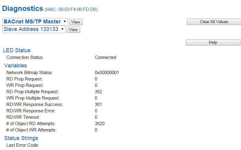
Revision History ............................................................................................................................................ 5
Overview ....................................................................................................................................................... 6
Hardware Platforms ...................................................................................................................................... 7
   Hardware – NNA1 ..................................................................................................................................... 8
   Powering the Gateway .............................................................................................................................. 8
   Port Configuration..................................................................................................................................... 9
   RS232 pinouts: .......................................................................................................................................... 9
   RS485 pinouts: .......................................................................................................................................... 9
Mounting with a DIN Rail ............................................................................................................................ 10
   Installing .................................................................................................................................................. 10
   Removing ................................................................................................................................................ 10
Accessing the Main Page............................................................................................................................. 11
   Error: Main Page Does Not Launch ......................................................................................................... 12
Committing Changes to the Settings .......................................................................................................... 13
Main Page ................................................................................................................................................... 14
Device Configuration................................................................................................................................... 15
Network Configuration ............................................................................................................................... 16
Modbus TCP/IP Client Configuration .......................................................................................................... 17
Modbus TCP/IP Client Device Configuration .............................................................................................. 18
   Configuring Read and Write Scan Lines .................................................................................................. 20
BACNet MS/TP Master Configuration ......................................................................................................... 22
BACnet MS/TP Master Device Configuration ............................................................................................. 23
   Configuring Read Scan Lines ................................................................................................................... 24
   Configuring Writes Scan Lines................................................................................................................. 24
Mapping - Transferring Data Between Devices .......................................................................................... 25
Display Mapping and Values ....................................................................................................................... 26
   Display Data ............................................................................................................................................ 26
   Display String........................................................................................................................................... 29
Display String use case ................................................................................................................................ 31
Data and String Mapping – Auto-Configure................................................................................................ 32
Data Mapping – Explanation ....................................................................................................................... 33
Data Mapping – Adding Diagnostic Information ........................................................................................ 34
String Mapping – Explanation ..................................................................................................................... 38
Mapping – Auto-Configure Mode to Manual Configure Mode .................................................................. 39
  Real Time Automation, Inc.                 3                                              1-800-249-1612
Mapping – Manual Configure Mode to Auto-Configure Mode .................................................................. 40
View as Text ................................................................................................................................................ 41
   Data Mapping.......................................................................................................................................... 41
   String Mapping ........................................................................................................................................ 41
   Base Triggering – Data Validiation Triggering ......................................................................................... 42
Security Configuration ................................................................................................................................ 44
   Security Configuration-Security Levels ................................................................................................... 45
   Security - Log In ....................................................................................................................................... 46
   Security - Log Out .................................................................................................................................... 46
Email Configuration .................................................................................................................................... 47
Alarm Configuration.................................................................................................................................... 48
   Diagnostics – Alarm Status...................................................................................................................... 50
   Alarms – Active ....................................................................................................................................... 50
   Alarms – Clear ......................................................................................................................................... 51
Change of State (COS) Configuration .......................................................................................................... 52
Diagnostics Info ........................................................................................................................................... 53
   Diagnostics Mapping ............................................................................................................................... 53
Diagnostics – Modbus TCP/IP Client ........................................................................................................... 54
Diagnostics – BACnet MS/TP Master .......................................................................................................... 59
LED Configuration ....................................................................................................................................... 63
Configuration Files ...................................................................................................................................... 64
   Export Configuration ............................................................................................................................... 64
   Import Configuration .............................................................................................................................. 64
Save and Replace Configuration Using SD Card .......................................................................................... 66
   Saving Configuration Using SD Card........................................................................................................ 66
   Replacing Configuration Using SD Card .................................................................................................. 66
Intelligent Reset Button .............................................................................................................................. 67
Utilities ........................................................................................................................................................ 68

     Real Time Automation, Inc.                                              4                                                      1-800-249-1612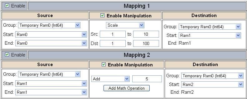
Revision History
Version       Date                                                 Notes

  8.4.5     11/18/2019   Features Added
                         1. Released OPC UA Server (US) Protocol
                         2. Ability to now Import/Export Template Files with out an FTP session.
                         Bug Fixes
                         1. Updated Profinet Server (PS) on N34 hardware Platform
                         2. Updated Wi-Fi software

  8.6.0      2/28/20
                         Bug Fixes
                         1. Omron Plc Communication fixes for EtherNet/IP
                         2. Profinet GSDML Substitute values fix

  8.7.4       9/1/20     Features Added:

                         1. BMS, BM, DFM, DS, DM, TCP, USB, PBS have been ported to the latest base software.
                         2. TCP,BMS,BM now Available on N2E and N2EW hardware Platform
                         3. New ASCII Mode Available on TCP/A/USB/WI protocols
                         4. User Guides updated with more examples

                         Bug Fixes:

                         1. Improved Data Mapping and String Mapping performance

                         2. Improved functionality/performance on EC,ETC,ES,MC,MS,BS,BC, A,,WI,PS protocols.

 8.7.22       4/6/21     Features Added:

                         1. Support for RSLogix Versions 32 + with unsigned data type support
                         2. ETC now support Long integer files (L files) for MicroLogix PLCS that support them
                         3. SC now supports data block (DB) access

  Real Time Automation, Inc.                     5                                     1-800-249-1612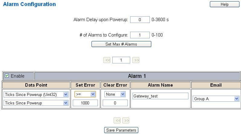
Overview
The 460MCBM-NNA1 gateway connects up to 32 Modbus TCP Servers with as many as 32 BACnet MS/TP
Slaves. By following this guide, you will be able to configure the 460MCBM-NNA1 gateway.

For further customization and advanced use, please reference the appendices located on the CD or
online at: http://www.rtautomation.com/product/460-gateway-support/.

If at any time you need further assistance, do not hesitate to call Real Time Automation support.
Support Hours are Monday-Friday 8am-5pm CST

Toll free: 1-800-249-1612
Email: support@rtautomation.com

   Real Time Automation, Inc.                    6                                  1-800-249-1612
Hardware Platforms
The 460 Product Line supports a number of different hardware platforms. There are differences in how
they are powered, what serial settings are supported, and some diagnostic features supported (such as
LEDs). For these sections, be sure to identify the hardware platform you are using.

To find which hardware platform you are using:

1) Look on the front or back label of the unit for the part number.
2) On the webpage inside the gateway, navigate to the dropdown menu under Other and select
   Utilities. Click the Listing of Revisions button. The full part number is displayed here.

Once you have the full part number, the platform will be the number following the “-N”:

   Real Time Automation, Inc.                    7                                1-800-249-1612
Hardware – NNA1

Powering the Gateway
1) Connect a 12-24 VDC power source to the gateway, Red Wire = (+) Black Wire = (-).
   a) The unit draws 175mA @ 12 V.

   Real Time Automation, Inc.                  8                                 1-800-249-1612
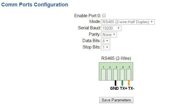
Port Configuration
The Port Configuration page is where you set port specific parameters. These settings must match the
settings of the device(s) that you are connecting to.

Only 1 mode can be configured for this hardware. Below are the wiring pinouts for each mode.

When you have completed your port configuration, click the Save Parameters button.

RS232 pinouts:

RS485 pinouts:

   Real Time Automation, Inc.                   9                                 1-800-249-1612
Mounting with a DIN Rail
    Installing
   Follow these steps to install your interface converter.
1) Mount your DIN Rail.
2) Hook the bottom mounting flange under the DIN Rail.
3) While pressing the 460MCBM-NNA1 against the rail, press up to engage the spring loaded lower clip and
    rotate the unit parallel to the DIN Rail.
4) Release upward pressure.

                                                                                DIN Rail

                                                                           Spring Loaded Lower Clip

    Removing
   Follow these steps to remove your interface converter.
1) Press up on unit to engage the spring loaded lower clip.
2) Swing top of the unit away from DIN Rail.

       Real Time Automation, Inc.                    10                             1-800-249-1612
Accessing the Main Page
The following steps will help you access the browser based configuration of the gateway. By default,
DHCP is enabled. If the gateway fails to obtain an IP address over DHCP it will Auto IP with 169.254.X.Y.
For more information on your Operating system network setting refer to the Access Browser
Configuration Doc on the CD or download from our support web site.
1) Insert the provided CD-ROM into a computer also on the network.
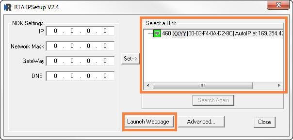
2) Run the IPSetup.exe program from the CD-ROM.
3) Find unit under “Select a Unit”.
a. Change Gateway’s IP address to match that of your PC if DHCP has failed.
i. You will know DHCP has failed if the gateway’s IP address is AutoIP at 169.254.X.Y.
ii. If successful, it will say DHCP’d at ex: 192.168.0.100 or however your DCHP Client is set up.
b. If you do not see the gateway in this tool, then your PC is most likely set up as a static IP.
i. Change your PC’s network settings to be DHCP. If DHCP fails, then it will change to be on the 169.254.x.y
network.
ii. Relaunch the IP Setup tool to see if gateway can be discovered now.
4) Click Launch Webpage. The Main page should appear.
Default setting is set to DHCP. If DHCP fails, default IP Address is 169.254.x.y
Real Time Automation, Inc. 11 1-800-249-1612Error: Main Page Does Not Launch
If the Main Page does not launch, please verify the following:
1) Check that the PC is set for a valid IP Address
a. Open a MS-DOS Command Prompt
b. Type “ipconfig” and press enter
c. Note the PC’s IP Address, Subnet, and Default Gateway
2) The gateway must be on the same Network/Subnet as the PC whether it’s setup for DHCP or Static.
Once you have both devices on the same network, you should be able to ping the gateway using a MS-
DOS Command Prompt.
The Screenshot above shows a gateway that is currently set to a static IP Address of 192.168.0.100.
If you are able to successfully ping your gateway, open a browser and try to view the main page of the
gateway by entering the IP Address of the gateway as the URL.
Real Time Automation, Inc. 12 1-800-249-1612Committing Changes to the Settings
• All changes made to the settings of the gateway in Configuration Mode will not take effect until the
gateway is restarted via the webpage. Changes will not be stored if the gateway’s power is removed
prior to a reboot.
• NOTE: The gateway does not need to be restarted after every change. Multiple changes can be made
before a restart, but they will not be committed until the gateway is restarted.
• When all desired changes have been made, press the Restart Now button.
• The webpage will redirect to our rebooting page shown below:
• The reboot can take up to 20 seconds.
o If the IP address has not been modified, the gateway will automatically redirect to the main page.
o If the IP address was modified, a message will appear at the top of the page to instruct the user to
manually open a new webpage at that new IP.
Real Time Automation, Inc. 13 1-800-249-1612Main Page
The main page is where important information about your gateway and its connections are displayed.
Mode (orange box below):
Running Mode:
- Protocol communications are enabled
- Configuration cannot be changed during Running Mode. If changes are needed, click the Configuration
Mode button shown in the green box below
Configuring Mode:
- Protocol communication is stopped and no data is transmitted
- Configuration is allowed
Navigation (green box below):
You can easily switch between modes and navigate between pages (Configuration, Diagnostics, and
Other pages) using the buttons on the left hand side.
Real Time Automation, Inc. 14 1-800-249-1612Device Configuration The device configuration area is where you assign the device description parameter. Changes can only be made when the gateway is in Configuration Mode. Once you are done configuring the Description, click the Save Parameters button. Real Time Automation, Inc. 15 1-800-249-1612
Network Configuration
 The network configuration area is where you assign the IP address and other network parameters.
 Changes can only be made when the gateway is in Configuration Mode.

 Once you are done configuring the Network Settings, click the Save Parameters button.

 If you are changing the IP Address of the gateway, the change will not take effect until the unit has been
 rebooted. After reboot, you must enter the new IP Address into the URL.

It is recommended to leave the DNS Gateway set to 0.0.0.0 and the Ethernet Link as
Auto-Negotiate. If configuring the gateway to use E-mail, the DNS Gateway must be
set.

    Real Time Automation, Inc.                    16                                  1-800-249-1612
Modbus TCP/IP Client Configuration
Click the Modbus TCP/IP Client button to access the configuration page.
1) Select which Network Interface to use for this Modbus TCP/IP connection. If using single port
hardware, the Network Interface will default to Ethernet port only.
2) Delay Between Messages: Enter the length of time to delay between read and write scan line
requests (ms).
3) Response Timeout: Enter the amount of time the gateway should wait before a timeout is
issued for a read/write request (ms).
4) Delay Between Connect Attempts: Enter the amount of time the gateway should wait between
attempts to connect to the PLC.
5) Dependency Protocol: If enabled, Modbus TCP/IP communication will stop if communication to
the selected protocol is lost.
Real Time Automation, Inc. 17 1-800-249-1612Modbus TCP/IP Client Device Configuration
The bottom area of the Modbus TCP/IP Client Configuration page lets you configure up to 32 external
Modbus TCP/IP server devices.
1) To add additional server connections, click the -Select- dropdown under Modbus TCP/IP Client
Device List and select Add Generic Server option.
a) If you are configuring multiple devices click > to navigate to another device.
b) To create a new server with the same parameters already configured from another server, click
the -Select- dropdown and select the Add from Modbus TCP/IP X option (where X represents
the server you wish to copy parameters from). Once created, you can make any additional
changes needed to that new server.
c) To remove a device, navigate to the server to delete using the > buttons and click the
Delete Server button.
d) Click the Save Parameters button to save changes before restarting or going to another
configuration page.
2) The Enable check box should be selected for the device.
3) Enter a Device Label to identify the device within the gateway.
4) Enter the unique IP Address that matches the server. If this value doesn’t match, the gateway will
timeout.
5) Enter the TCP Port for the Modbus TCP/IP client to open a connection on. Default port for Modbus
TCP/IP is 502.
6) Force Function Code 15/16 for Single Writes: Only select this if the Modbus TCP/IP device does not
support Modbus Function Code 5/6.
7) Enable 0-Based Addressing: Check ONLY if the server you are connecting to begins their register
numbering at 0 OR they specify that their device addresses are 0-based.
Real Time Automation, Inc. 18 1-800-249-16128) Bit Pack: Select the formatting of the Coil Status/Input Status. Automap will use this packing size to
map coils to/from the other protocol. The bit pack selection here should match that of the other
protocol. The starting address is considered Bit 0 and is the low-order bit.
9) To enable data swapping, select the required Swap Indicator. If the bytes appear in the wrong
order, enable swapping to change the data. This swapping does NOT change coils and their ordering
inside the Bit Pack.
10) Enter the number of read scan lines and write scan lines.
11) Click the Generate Scan Lines button to have the read and write scan lines auto-generate for you.
You may manually configure the read and write scan lines after they have been generated.
Real Time Automation, Inc. 19 1-800-249-1612Configuring Read and Write Scan Lines
Follow these steps to manually configure Read and Write Scan Lines.
1) Click the View Read Scan Lines or View Write Scan Lines button.
2) Enter a Unit ID for the Client to communicate to.
3) Select a Point Type for each Scan Line. Options include: Coil Status, Input Status, Input Registers, and
Holding Registers.
a) Note: Input/Holding Registers have a data type associated with them.
b) String Point Type- If the mating protocol supports strings, you may select string as a point type
in Modbus. With this point type, 2 characters will be packed into a single register and the first
register will be set aside for the length.
c) EX: 4x Hold Reg (String) with a Starting Address of 1 for a length of 5 Registers, this means that
Register 1 will hold the length of the string and Registers 2-5 will hold the string contents. So,
this string can contain a max of 8 characters.
1) Enter a Starting Address (This will be 1 based, if your device is 0 based then check the Enabled 0-
Based Addressing box).
a) Note: Some manufactures documentation may call out the Starting Address as 00001, 10001,
30001 or 40001. Don’t include the first value as this represents (0) coil, (1) Input Status, (3) Input
Register and (4) Holding Register.
Real Time Automation, Inc. 20 1-800-249-16122) Enter the # of consecutive points to read for that point/data type. See the Scan Line Data Limit section at the bottom of the webpage for max values in a scan line. Real Time Automation, Inc. 21 1-800-249-1612
BACNet MS/TP Master Configuration
Click the BACnet MSTP Master button to access the configuration page.

   1) Serial Port: Select which serial port is being used for communication. This port must be
      configured on the Port Configuration page. If it has not yet been configured, it will display
      Disabled after the Port description in this dropdown.

   2) Enter a unique Instance identifier for the gateway. This Instance must be unique on the BACnet
      MS/TP network.
   3) Enter a unique MAC identifier for the gateway. This MAC must be unique on the BACnet MS/TP
      network.
   4) Max Master: Enter the maximum MAC ID that the gateway will communicate with on the
      BACnet MS/TP network. This value should be equal to or greater than the largest MAC ID on the
      MS/TP Network. The gateway cannot communicate with any MAC ID that is greater than the
      value entered in this field. In an ideal network, this should match the other devices on the
      BACnet MS/TP network.
   5) Enter a Name, Description and Location for the gateway. These are used to identify the gateway
      on the BACnet MS/TP network.
   6) Delay Between Messages: Enter the length of time to delay between read and write scan line
      requests (ms).
   7) Response Timeout: Enter the amount of time the gateway should wait before a timeout is
      issued for a read/write request(s).
   8) Dependency Protocol: If enabled, BACnet MS/TP communication will stop if communication to
      the selected protocol is lost.

   Real Time Automation, Inc.                   22                                   1-800-249-1612
BACnet MS/TP Master Device Configuration
The bottom area of the BACnet MS/TP Master Configuration page lets you configure up to 32 external
BACnet MS/TP devices.
1) To add additional Slave connections, click the -Select- dropdown menu under BACnet MS/TP
Master Device List and select Add Generic Slave option.
a. If you are configuring multiple devices click > to navigate to another device.
b. To create a new slave with the same parameters already configured from another slave,
click the -Select- dropdown and select the Add from BACnet MS/TP X option (where X
represents the slave you wish to copy parameters from). Once created, you can make
any additional changes needed to that new slave.
c. To remove a device, navigate to the slave to delete using the > buttons and click
the Delete Slave button.
d. Click Save Parameters to save your changes before a restart or going to another
configuration page.
2) The Enable check box should be selected for the device.
3) Enter a Device Label to identify the device within the gateway.
4) Enter the unique Instance that matches the slave. If this value doesn’t match, the gateway will
timeout.
5) Bit Pack: Select the formatting of the Binary Input/Output/Value Objects. Automap will use this
packing size to map binary objects to/from the other protocol. The bit pack selection here
should match that of the other protocol. The starting address is considered Bit 0 and is the low-
order bit.
6) Priority Array: Select the Priority Array index to use for the Writeable Commandable BACnet
Objects.
7) Enter the number of Read Scan Lines and Write Scan Lines.
8) Click the Generate Scan Lines button to have the read and write scan lines auto-generate for
you. You may manually configure the read and write scan lines after they have been generated.
Real Time Automation, Inc. 23 1-800-249-1612Configuring Read Scan Lines
Follow these steps to manually configure Read Scan Lines.
1) Select View Read Scan Lines if not already selected.
2) Select an Object Type for each Scan Line. Options include: Analog Input, Analog Output, Analog
Value, Binary Input, Binary Output, Binary Value, and Multi-State Input, Multi-State Output,
Multi-State Value, CSV (CharacterString Value).
3) Enter a Starting Object.
4) Enter the # of consecutive objects to read for that object type. You can enter a value of 1 to 128.
Configuring Writes Scan Lines
Follow these steps to manually configure Write Scan Lines.
1) Select View Write Scan Lines if not already selected.
2) Select an Object Type for each Scan Line. Options include: Analog Output, Analog Value, Binary
Output, Binary Value, Multi-State Output, Multi-State Value, and CSV (CharacterString Value).
3) Enter a Starting Object.
4) Enter the # of consecutive objects to write for that object type. You can enter a value of 1 to
128.
Real Time Automation, Inc. 24 1-800-249-1612Mapping - Transferring Data Between Devices There are 5 ways to move data from one protocol to the other. You can combine any of the following options to customize your gateway as needed. Option 1 – Data Auto-Configure Mappings: The gateway will automatically take the data type (excluding strings) from one protocol and look for the same data type defined in the other protocol. If there isn’t a matching data type, the gateway will map the data to the largest available data type. See Data Auto- Configure section for more details. Option 2 – String Auto-Configure: The gateway will automatically take the string data type from one protocol and map it into the other. See String Auto-Configure section for more details. Option 3 – Manual Configure Mappings: If you don’t want to use the Auto-Configure Mappings function, you must use the manual mapping feature to configure translations. Option 4 – Manipulation/Scaling: You can customize your data by using math operations, scaling, or bit manipulation. See Data Mapping-Explanation section for more details. Option 5 – Move Diagnostic Information: You can manually move diagnostic information from the gateway to either protocol. Diagnostic information is not mapped in Auto-Configure Mappings Mode. See Diagnostic Info section for more details. Going from Manual Mapping to Auto-Mapping will delete ALL mappings and manipulations configured. Real Time Automation, Inc. 25 1-800-249-1612
Display Mapping and Values
The Display Data and Display String pages are where you can view the actual data for each mapping that
is set up.

Display Data
Click the Display Data button to view how the data is mapped and what the values of each mapping are.

Here you will see how each data point (excluding strings) is mapped. To view, select the device from the
dropdown menu and click View to generate the information regarding that device. Then select either
the Protocol 1 to Protocol 2 or Protocol 2 to Protocol 1 button, correlating to the direction you wish to
see the data.

   Real Time Automation, Inc.                    26                                 1-800-249-1612
This page is very useful when verifying that all data is mapped somehow from one protocol to another.
If a data point is not mapped, it will display on this page in a yellow highlighted box. The Display Data
page will display up to 200 mappings per page, simply navigate to the next page for the additional
mapping to display.

In the above example, we see the following:

    •   Modbus register 400001 from Slave 1 is being mapped to AI1 on BACnet

    •   Nothing is being moved from Modbus register 400002 to AI2 on BACnet because the mapping is
        disabled

    •   Modbus register 400003 from Slave 1 is being mapped to AI3 on BACnet

NOTE: If a data point is mapped twice, only the first instance of it will show here. EX: If Modbus 400001
& 400040 from Slave 1 are both mapped to AI1, only 400001 will show as being mapped to AI1.

If there are values of “- - “on this page, it indicates that the source has not yet been validated and no
data is being sent to the destination.

The example below reflects the Modbus to PLC flow of data. The Modbus (left side) is the source and
the PLC (right side) is the destination.

    •   The 460 gateway has received valid responses from Modbus registers 400001- 400005 and
        therefore can pass the data on to the PLC tag called MC2PLC_INT.

    •   The 460 gateway has NOT received valid responses from Modbus register 400011 & 400012. As
        a result, the data cannot be passed to the PLC tag ETC01_GN0_INT2 and indicates so by using “-
        - “in the value column of the table.

   Real Time Automation, Inc.                     27                                   1-800-249-1612
To view the actual data mappings, click the Edit Mapping button. For more details, see the Data Mapping-Explanation section. To view the data mappings purely as text, click the View as Text button. For more details, see the View Data Mapping as Text section. Real Time Automation, Inc. 28 1-800-249-1612
Display String
Click the Display String button to view what the values of each Parsing and/or Concatenating strings are,
you can also click on the Edit Mapping to view the mapping of each string.

To view the source or destination groups from a string, click the dropdown menu to generate the
information regarding that device. The string data will be displayed in both Hex and ASCII (only the ASCII
data is sent). The example below shows data that is coming from the source device. A group will be
displayed for each Parsing/Concatenating String field that is configured.

In the Group drop down, “Line1” is defined on the ASCII Device configuration page and “Barcode
Scanner” is defined in the ASCII Parsing configuration.

   Real Time Automation, Inc.                    29                                  1-800-249-1612
If there are values of “Data Not Valid “on this page, it indicates that the source has not been validated
yet and no data is being sent to the destination.

NOTE: You can view the whole string data by clicking on Diagnostics Info drop down and navigating to
ASCII Diagnostics page. You will also have to select the port you want to view in the dropdown below
ASCII.

To view the string mappings, click the Edit Mapping button. For more details see the String Mapping-
Explanation section.

               NOTE: Only String data types can be mapped to another String data type.

To view the string mappings purely as text, click the View as Text button. For more details see the View
String Mapping as Text section.
   Real Time Automation, Inc.                     30                                  1-800-249-1612
Display String use case Sending a message of “RTA,Support,Rocks” from an ASCII device to the RTA unit. The ASCII Parsing Configuration would look like my example below. There are more detailed examples of what all the fields represent in the ASCII Parsing section. The message is broken up into 3 “Groups” or Parsing fields. To view the Entire message, click on the Diagnostic drop down, select Diagnostics Info. Select ASCII, click view, select your Port. Whole data will be in the Last Message Sent Diagnostic box. Real Time Automation, Inc. 31 1-800-249-1612
Data and String Mapping – Auto-Configure
The Auto-Configure function looks at both protocols and will map the data between the two protocols
as best as it can so that all data is mapped. Inputs of like data types will map to outputs of the other
protocols like data types first. If a matching data type cannot be found, then the largest available data
type will be used. Only when there is no other option is data truncated and mapped into a smaller data
type.

If the Auto-Configure function does not map the data as you want or you want to add/modify the
mappings, you may do so by going into Manual Configure mode.

The following are examples of the Auto-Configure function.

1) This example shows a common valid setup.

        a. Both Source values were able to be mapped to a corresponding Destination value.

2) This example shows how Auto-Configure will make its best guess.

        a. The 32-bit Float from the Source location could not find a matching Destination data-type.
           After all other like data types were mapped, the only data type available was the 2nd 32-bit
           Uint data type. Auto-Configure was completed even though the data in the Float will be
           truncated.

   Real Time Automation, Inc.                    32                                  1-800-249-1612
Data Mapping – Explanation
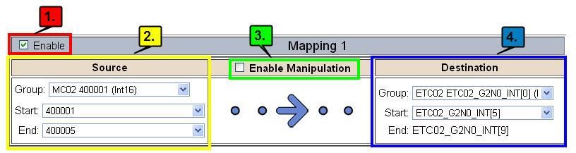
Below are the different parts that can be modified to make up a data mapping.
1) Enable (red box above): Check to enable mapping. If not checked, this mapping is skipped.
2) Source Field (yellow box above):
a) Group - Select the data group you set up in the protocol config to use for this mapping.
b) Start - This is the starting point for this mapping.
c) End - This is the final point to be included for this mapping.
3) Manipulation Area (green box above):
a) Enable the Data Manipulation. This can be enabled for any mapping.
b) Click Add Math Operation for each operation needed. Up to 3 are allowed unless you are using
the Scale, Set Bit, or Invert Bit functions. If using Scale, Set Bit, or Invert Bit, then only 1
operation is allowed.
c) Select the Operation(s) to perform.
i) Math Operations are performed in the order they are selected.
ii) If more than one point is selected on the source, the Math Operations will be performed on
every point.
d) Enter the value(s) for the operation.
Example of Add (similar for Subtract, Example of Scale. This will Example of Set Bit (similar to
Multiple, Divide, and MOD). This will scale the source values from 1- Invert Bit). This will take the value
add a value of 10 to the source field 10 into 1-100 for the of the 0th source bit and copy it
before it is written to the destination destination. into the value of the 5th
field. destination bit.
4) Destination Field (blue box above):
a) Group - Select the data group you set up in the protocol config to use for this mapping.
b) Start - This is the starting point for where the data is being stored.
c) End - The End point is derived from the length of the source and cannot be modified.
Real Time Automation, Inc. 33 1-800-249-1612Data Mapping – Adding Diagnostic Information
Data Mapping offers 5 different types of information in addition to any scan lines specified for each
protocol.
IMPORTANT NOTE: Only add Diagnostic Information AFTER both sides of the gateway have been
configured. If changes to either protocol are made after diagnostic information has been added to the
mapping table, it is necessary to verify all mappings. Remapping may be necessary.
1) Temporary Ram (Int64)
a) This offers five levels of 64bit Integer space to assist in multiple stages of math operations. For
example, you may wish to scale and then add 5. You can set up a single translation to scale with
the destination as the temporary ram. Then another translation to add 5 with the source as the
temporary ram.
b) The gateway will automatically convert the Source to fit the Destination, so there is no need for
Int 8, 16, 32 since the 64 may be used for any case.
In this example, Ram0 is scaled into Ram1. Ram1 is then increased by 5 and stored into Ram2.
Ram0 and Ram2 could be considered a source or destination group.
2) Temporary Ram (Double)
a) This is like the Temporary Ram (Int 64), except manipulations will be conducted against the
64bit floating point to allow for large data.
3) Ticks Per Second
a) The gateway operates at 200 ticks per second. This equates to one tick every 5ms. Thus,
mapping this to a destination will give easy confirmation of data flow without involving one of
the two protocols. If data stops on the destination end, then the RTA is offline.
Real Time Automation, Inc. 34 1-800-249-16124) XY_NetBmpStat
a) If a protocol is a Client/Master, there is a Network Bitmap Status that is provided on the
Diagnostics Info page under the Variables section.
b) Since a Client/Master may be trying to communicate with multiple devices on the network, it
may be beneficial to know if a Server/Slave device is down. By using this Network Bitmap Status,
you can expose the connection statuses of individual devices. Values shown are in HEX.
i) 0x00000002 shows that only device 2 is connected
ii) 0x00000003 shows that only devices 1 and 2 are connected
iii) 0x0000001f shows that all 5 devices are connected (shown in image above)
c) There are multiple ways to map the NetBmpStat.
Option 1: Map the whole 32bit value to a destination. Example below shows the
NetBmpStat is going to an Analog BACnet object. Using a connection of 5 Modbus Slave
devices AI1 will show a value of 31.0000. Open a calculator with programmer mode and
type in 31, this will represent bits 0 – 4 are on. This mean all 5 devices are connected
and running.
If using an AB PLC with a Tag defined as a Dint, then expand the tag within your RSlogix
software to expose the bit level and define each bit as a description such as device1,
device2, etc.
Option 2: You can extract individual bits from the NetBmpStat by using the Set Bit
Manipulation and map those to a destination. You’ll need a mapping for each device you
want to monitor. Example below shows Modbus device 2 (out of 5) is being monitor to a
BACnet Binary Object. You can define the object in the BACnet Name configuration.
Real Time Automation, Inc. 35 1-800-249-16125) Status_XY
a) There are two Statuses provided, one for each protocol. This gives access to the overall status of
that Protocol. Each Bit has its own meaning as follows:
Common Status: 0x000000FF (bit 0-7)1st byte
Hex: Bit Position: Decimal: Explanation:
0x00 0 0 if we are a Slave/Server
0x01 0 1 if we are a Master/Client
0x02 1 2 connected (0 not connected)
0x04 2 4 first time scan
0x08 3 8 idle (usually added to connected)
0x10 4 16 running (usually added to connected)
0x20 5 32 bit not used
0x40 6 64 recoverable fault
0x80 7 128 nonrecoverable fault
For this example, the ETC Status is mapped to a PLC tag called PLC_Status
Example: ETC Status is 0x00000013 (19 decimal), here is the break down
Hex Bit Decimal Explanation
0x01 0(on) 1 if we are a Master/Client
0x02 1(on) 2 connected (0 not connected)
0x10 4(on) 16 running (usually added to connected)
Total: 0x13 19
External Faults: 0x0000FF00 (bit 8-15)2nd byte
Hex: Bit Position: Decimal: Explanation:
0x00 8 0 local control
0x01 8 256 remotely idle
0x02 9 512 remotely faulted
0x04 10 1,024 idle due to dependency
0x08 11 2,048 faulted due to dependency
Recoverable Faults: 0x00FF0000 (bit 16-23)3rd byte
Hex: Bit Position: Decimal: Explanation:
0x01 16 65,536 recoverable fault - timed out
0x02 17 131,072 recoverable fault - Slave err
Real Time Automation, Inc. 36 1-800-249-1612Non-Recoverable Faults 0xFF000000 (bit 24-31)4th byte
Hex: Bit Position: Decimal: Explanation:
0x01 24 16,777,216 nonrecoverable fault –
task fatal err
0x02 25 33,554,432 nonrecoverable fault –
config missing
0x04 26 67,108,864 nonrecoverable fault –
bad hardware port
0x08 27 134,217,728 nonrecoverable fault –
config err
0x10 28 268,435,456 Configuration Mode
0x20 29 536,870,912 No Ethernet Cable Plugged In
For this example, the MC Status is mapped to a PLC tag called MC_Status
Example: MC Status is 0x00010041 (65601 decimal), here is the break down, we know that bytes 1 and 3
are being used, so here is the break down,
Common Status:
Hex: Bit: Decimal: Explanation:
0x01 0(on) 1 if we are a Master/Client
0x40 6(on) 64 recoverable fault
Recoverable Faults:
Hex: Bit: Decimal: Explanation:
0x01 16 65,536 recoverable fault – timed
Total: 0x010041 65,601
Real Time Automation, Inc. 37 1-800-249-1612String Mapping – Explanation Below are the different parts that can be modified to make up a string mapping. String data types can only be mapped to other string data types. There is no manipulation that can be done on the string. 1) Enable (red box above): Check to enable mapping. If not checked, this mapping is skipped. 2) Source Field (yellow box above): a) Group - Select the string data group you set up in the protocol config to use for this mapping. b) String - This is the string used for this mapping. 3) Destination Field (green box above): a) Group - Select the string data group you set up in the protocol config to use for this mapping. b) String - This is the string where the data is being stored. Real Time Automation, Inc. 38 1-800-249-1612
Mapping – Auto-Configure Mode to Manual Configure Mode
To transition from Auto-Configure Mapping Mode to Manual Configure Mode, click the dropdown at the
top of the Mapping Configuration page and select Manual Configure.

After you click this button, you will be prompted to confirm if this is really what you want to do.

Click OK to proceed to Manual Configure Mode or click Cancel to remain in Auto-Configure Mappings
Mode.

Once OK is clicked, there are 2 options on how to proceed from here.

1) To keep the mappings that are already configured press OK.

    a) You would want this option if you are adding additional mappings or you want to modify the
       mapping(s) that already exist.

2) To delete the mappings that are already there and start over press Cancel.

To modify the number of mappings, enter a number in the text field next to # of Mappings to Configure
and click the Set Max # of Mappings button. You can always add more mappings if needed.

   Real Time Automation, Inc.                     39                                  1-800-249-1612
Mapping – Manual Configure Mode to Auto-Configure Mode To transition from Manual Configure Mode to Auto-Configure Mapping Mode, click the dropdown menu at the top of the Mapping Configuration page and select Auto-Configure Mappings. Click OK to proceed to delete all current mappings and go back to Auto-Configure Mappings Mode. Click Cancel to keep all mappings and remain in Manual Configure Mode. NOTE: Once you revert to Auto-Configure Mapping Mode there is no way to recover the mappings you lost. Any mappings you previously have added will be deleted as well. Real Time Automation, Inc. 40 1-800-249-1612
View as Text

Data Mapping
The View as Text page displays the point to point mapping(s) you set up in the Data Mapping section.
This will also display any manipulation(s) that are configured.

Each line on this page will read as follows:

        Mapping number: source point Len: Number of points mapped -> manipulation (if blank then
        no manipulation) -> destination point

If you are looking for a specific point to see if it is mapped, you can do a find in this text box for your
point in question. Example: you defined 20 Registers starting at register 1 and want to see if 400011 is
mapped. If it is not in this text box, then it is not mapped, and no data will be transferred.

This is the text display for the example shown under the Data Mapping- Adding Diagnostic Information
section.

String Mapping
The View as Text page displays the string mapping(s) you set up in the String Mapping section.

Each line on this page will read as follows:

        Mapping number: source point -> Copy -> destination point

If you are looking for a specific point to see if it is mapped, you can do a find in this text box for your
point in question. Example: you defined 20 String Tags in the PLC and want to see if “Test_String” in the
Logix PLC is mapped. If it is not in this text box, then it is not mapped, and no data will be transferred.

   Real Time Automation, Inc.                      41                                   1-800-249-1612
Base Triggering – Data Validiation Triggering
With Base Triggering, you will be marking data as “Invalid” and force RTA Master/Controller/Client
protocols to read all the read data points sources until ALL source protocols data is valid. You will be
able to utilize the Handshake to map over to Technology Trigger and/or back over to your source
protocol for reference.
How does this work?
1) Map the Triggering Variable (Source) over to Trigger # (Dest).
2) If Trigger # value changes states mark all Trigger # protocols read data as “Invalid”.
3) Read all source read data points until ALL source read data is valid.
4) Handshake # value is set equal to Trigger # value.
5) Map Handshake # to reference data point.
Note: # is an internal reference to the Server/Slave number you are settings up. ex. RTA
Server/Slave products can only be Trigger 1 and Handshake 1 since we are only 1 device. If RTA is a
Master/Client, then you can have a Trigger# for each server/slave connected too.
How do you set this up?
In this example I’m using a 460MCBS. My Building Automation System wants to verify that all data read
from Modbus TCP/IP Server is valid.
1) Add an extra Analog Output for your Trigger. This tells the RTA to mark all data invalid.
a) You can define AI21 as your validation name in the Setup BACnet Names Configuration.
2) Add another Analog Input as reference for when data has been validated. When you write from
AO21 to validate data, the RTA will reply to AI40 saying “validation complete”.
Real Time Automation, Inc. 42 1-800-249-16123) Within the Data Mapping page manually add 2 additional mappings. 4) The first mapping is going to be the Data Validation Triggering. AO21 will write to the RTA, MC Trigger 1 will mark data invalid. 5) The second mapping, the MC Handshake will increment that all data is validated and write to AI21 “all data is validated”. The value of AI40 and AO21 should be the same. Real Time Automation, Inc. 43 1-800-249-1612
Security Configuration
To setup security on the 460 gateway, navigate to Other->Security Configuration. You can configure
Security for 3 administrators, 5 users, and 1 guest.
THIS IS NOT A TOTAL SECURITY FEATURE
The security feature offers a way to password protect access to diagnostics and configuration on
the network. The security feature does not protect against “Air Gap” threats. If the gateway can
be physically accessed, security can be reset. All security can be disabled if physical contact can
be made. From the login page, click the Reset Password button twice. You will be forced to do a
hard reboot (power down) on the gateway within 15 minutes of clicking the button. This process
should be used in the event a password is forgotten.
Note: Only Admins have configuration access to all web pages.
1) Log Out Timer: The system will automatically log inactive users off after this period of time.
NOTE: A time of 0 means that the user will not be automatically logged off. Instead, they must
manually click the Logout button.
2) Username: Enter a username, max of 32 characters.
3) Password: Enter a password for the username, max of 32 characters, case sensitive.
a. Re-enter the Password
4) E-mail: In case the password was forgotten, a user can have their password e-mailed to them if
e-mail was configured.
5) Hint: A helpful reminder of what the password is.
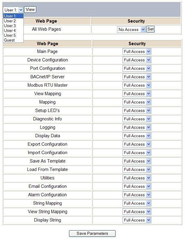
Real Time Automation, Inc. 44 1-800-249-1612Security Configuration-Security Levels
Each webpage in the gateway can have a separate security level associated with it for each user.
Security Levels:
1) Full Access: Capability to view and configure a web page.
2) View Access: Capability to view a web page, but cannot configure parameters.
3) No Access: No capability of viewing the web page and page will be removed from Navigation.
Real Time Automation, Inc. 45 1-800-249-1612Security - Log In Username: Name of the user to login. Password: Password of the user to login. Log In: If login is successful, the user will be redirected to the Main Page. Send Password to Email: Sends the specified User’s Password to the email configured for that user. Display Hint: Displays the hint specified for the User if one was set up. Reset Password: This is used to reset security settings. Confirm reset password must be selected to confirm this action. Once confirmed, there is a 15 minute window to do a hard reset of the gateway by physically removing and restoring power from the gateway. Once power is restored, you may navigate to the IP address of the gateway as normal. Security - Log Out Once a user is done with a session they may click logout at the top of any page. The user may also be logged out for inactivity based off of the Log Out Timer specified during the configuration. Closing the browser is not sufficient to log out. Real Time Automation, Inc. 46 1-800-249-1612
Email Configuration
To setup e-mails on the 460 gateway, navigate to Other->Email Configuration.

You can configure up to 10 email addresses.

1)   SMTP Mail Username: The email address that the SMTP server has set up to use.
2)   SMTP Mail Password: If authentication is required, enter the SMTP Server’s password (Optional).
3)   SMTP Server: Enter the Name of the SMTP Server or the IP Address of the Server.
4)   From E-mail: Enter the e-mail that will show up as the sender.
5)   To E-mail: Enter the e-mail that is to receive the e-mail.
6)   E-mail Group: Choose a group for the user. This is used in other web pages.

Click the Save Parameters button to commit the changes and reboot the gateway.

     Real Time Automation, Inc.                  47                                1-800-249-1612
Alarm Configuration
To setup alarms on the 460 gateway, navigate to Other->Alarm Configuration.
1) Alarm Delay upon Powerup: At Powerup, the gateway will have values of ‘0’ stored for all data. This
may cause alarms to trigger before these values are updated by the mating protocols. Set this field
to provide needed time to update fields before considering values for alarms.
2) Enter the number of alarms to configure and click Set Max # Alarms to generate those lines.
3) In the Data Point Section:
a. Top dropdown: select the Data Group. This dropdown menu will contain all groups that go
from the gateway to the network.
b. Lower dropdown: select the Data Point’s Specific Point. This is used to select which point in
the group will be monitored for alarms.
4) In the Set Error Section:
a. Select the Set Error Operation in the top dropdown menu. Available options are , =,
!=, ==, and Change of State (COS). This is the operation that will be used to compare the
Data Point value against the Error Value to determine if the alarm needs to be set.
b. Select the Set Error Value. This value is used as: ‘Data Point’s Value’ ‘Operation’ ‘Value.’ Ex:
Ticks Since Powerup >= 1000. This will set the alarm after 1000 ticks have elapsed since the
unit powered up.
Real Time Automation, Inc. 48 1-800-249-16125) In the Clear Error Section:
a. Select the Clear Error Operation. Available options are , =, !=, ==, and Change of
State (COS). This is the operation that will be used to compare the Data Point value against
the Error Value to determine if the alarm needs to be cleared.
b. Select the Clear Error Value.
-Ex: Ticks Since Powerup >= 5000. This will clear the alarm after 5000 ticks have elapsed
since the unit powered up.
6) Enter an Alarm Name. This will make the alarm unique and will be available in the Alarm Status page
as well as in the email generated by the alarm.
7) Select an email to associate this alarm with. When an alarm is set, it sends an email. When an alarm
is cleared, it will also send an email.
Click the Save Parameters button to commit the changes to memory and reboot the gateway.
Real Time Automation, Inc. 49 1-800-249-1612You can also read