A Study on Universal Observation Control System And Its Application For LAMOST
←
→
Page content transcription
If your browser does not render page correctly, please read the page content below
Research in Astronomy and Astrophysics manuscript no.
                                              (LATEX: 20200439.tex; printed on February 2, 2021; 1:30)

                                              A Study on Universal Observation Control System And Its
arXiv:2102.00686v1 [astro-ph.IM] 1 Feb 2021

                                              Application For LAMOST

                                              Zheng Wang1,2 , Yuan Tian1,2 , Jian Li1 , Zi-Huang Cao1 and Yong-Heng Zhao1,2

                                              1
                                                  Key Laboratory of Optical Astronomy, National Astronomical Observatories, Chinese Academy of
                                                  Sciences, Beijing 100101, China; wzheng@bao.ac.cn
                                              2
                                                  University of Chinese Academy of Sciences, Beijing 100049, China

                                                      Abstract The observatory control system (OCS), a part of automated control of Large Sky
                                                      Area Multi-Object Fibre Spectroscopic Telescope (LAMOST), runs on the CentOS6 platform
                                                      and implements the communication between modules based on Common Object Request
                                                      Broker Architecture (CORBA). However, CORBA is complicated and has limited develop-
                                                      ment support; moreover, the official support for CentOS6 has ended. OCS inherently has
                                                      some shortcomings such as the over-concentration of control and the blocking of device sta-
                                                      tus processing, which hinder the realization of automated observation control of LAMOST.
                                                      Therefore, this study designs and implements a universal observation control system (UOCS)
                                                      for optical telescopes. The UOCS takes the device command as the basic execution unit, con-
                                                      trols the device execution logic using observation script, controls the observation logic by
                                                      event-driven messaging, and realizes mutual decoupling between modules via a distributed
                                                      control mode, thereby ensuring high system robustness. The UOCS performs significantly
                                                      better than OCS in terms of the observation performance, operator complexity, and com-
                                                      munication error. Currently, UOCS is applied to the automated control of some devices and
                                                      subsystems in LAMOST observation. It will be applied to the automated observation control
                                                      of Multi-channel Photometric Survey Telescope by 2021.

                                                      Key words: telescopes — techniques:miscellaneous – methods:observational — instrumen-
                                                      tation:miscellaneous

                                              1 INTRODUCTION

                                              The Large Sky Area Multi-Object Fibre Spectroscopic Telescope (LAMOST), also known as the Guo
                                              Shoujing Telescope, is a Schmidt optical reflecting telescope( Cui et al. 2012), located in the Xinglong
                                              Observatory of the National Astronomical Observatory of China (NAOC). Owing to its large aperture and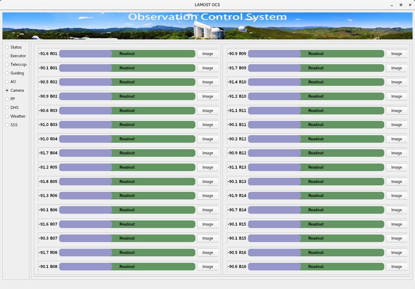
2                                                 Z.Wang et al.

it the most efficient telescope in terms of spectral acquisition worldwide( Zhao 2015). To date, LAMOST
has obtained a catalogue of more than 10 million astronomical spectra1 .
        An observatory control system (OCS), which is the communication center of a telescope, is a software
for autonomous observatory control that integrates important functions, such as selecting the observation
target, making observation flows, distributing commands, handling exceptions, controlling devices or sub-
systems, and human–computer interaction( Zhao 2000). Therefore, OCS is a key element in the autonomous
control of a telescope, and it is pivotal in integrating the functions of the entire telescope control system.
        The OCS is a distributed control system based on the CentOS6 computing platform, and it uses the
Common Object Request Broker Architecture (CORBA) as the middleware( Wang 2006). The design
and development of the OCS commenced in 2000 and was completed and applied to the LAMOST
in 2008( Sun et al.2008). Since then, OCS has been providing vital support for observations using the
LAMOST. However, as the LAMOST survey continues to gradually advance, a few shortcomings of the
OCS have been revealed, some of which may even make the OCS defunct. Some of these shortcomings are
listed below.
        1) Difficulties in upgrading and maintenance. Updates and maintenance are no longer available since
version 3.3 of CORBA (2012)2 , making CORBA incompatible with newer operating systems, such as
CentOS7. The ACE ORB (TAO), which forms the basis for the communication functions of the OCS,
is a version of CORBA implemented based on the Adaptive Communication Environment (ACE) library.
However, the TAO has only limited third-party development support. Moreover, because the official support
for CentOS6 has ended, obtaining a stable and reliable system is difficult, rendering the security of OCS
vulnerable.
        2) Over-centralization of command control. Although the OCS adopts distributed control, it is dis-
tributed only among the internal modules. Furthermore, the device agent performs only the simple function
of translating the control commands and states between the OCS and devices, and it plays no role in the
business logic of control. The command executor, being the core component, integrates the tasks of sending
commands, execution, and exception handling. This results in increased complexity of the business logic of
internal control, a higher degree of coupling with other modules, and lower stability of the entire system.
For example, if an error occurs in a parallel command, all parallel commands need to be re-executed, failing
which no subsequent command could be executed.
        3) Foreground and background are not separated. The necessity of separately restarting a single mod-
ule was not fully considered in the design of OCS. Therefore, if an error arises, it can be rectified only
by restarting the entire system—this interrupts the entire observation process, reducing the observation
efficiency.
        4) Status transmission channel is indistinguishable. The OCS status is classified into command exe-
cution status and device normal status: the former is fed back to the command executor to control the
observation process, while the latter is used to display the status of the subsystems or devices. No status
is prioritized, and all statuses are transmitted via a single channel. Consequently, if the channel is blocked
by the device’s normal status, the command executor cannot receive the command execution status, whose
    1   http://dr7.lamost.org/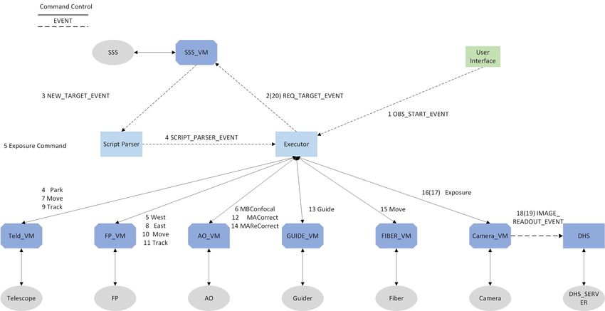
A Study on Universal Observation Control System And Its Application For LAMOST              3

logic priority is higher than that of the device normal status. Thus, subsequent commands cannot be exe-
cuted, resulting in interrupted observation flow.
   Owing to these shortcomings, the OCS can only be used for the manual control of some subsystems;
however, the control of other subsystems also requires manual intervention through the subsystem of the
control computer. This results in low observation efficiency and difficulties in operation and maintenance.
Further, as mentioned above, OCS could become unusable because of the incompatibility of CORBA and
newer operating systems (e.g., CentOS7). In view of these problems, a new control system must be devel-
oped and applied to the observation control of LAMOST.
   Accordingly, this study designs a universal observation control system (UOCS) based on the asyn-
chronous coroutine function of Python and implements it in an optical telescope. For a complete inclusion
of the design concepts of OCS, the advantages and disadvantages of OCS are summarized and analyzed,
and the overall reorganization design is performed comprehensively.Further, the developed UOCS is more
advanced than OCS, and has improved suitability for diverse astronomical observation scenarios. Based on
the device control command and the lightweight messaging middleware, ZeroMQ( Dworak 2012), an inde-
pendent data and message bus and a device control system are developed for UOCS. The execution logic
between the devices is controlled by observation scripts, and the serial–parallel distributed observation con-
trol is realized by combining the event and device commands. The UOCS performs command and exception
handling using independent device and service modules, and it realizes human–computer interaction for the
telescope by using the local user interface or network remote interface. The UOCS performs significantly
better than OCS in terms of the observation performance, operator complexity, and communication error.

2 DESIGN OF THE UOCS ARCHITECTURE

To reduce the degree of coupling of the internal modules and ensure a stable and efficient operation of
the telescope, we adopted a distributed control structure with separated foreground and background for the
UOCS (Figure 1).

     Fig. 1     Framework of the universal observation control system (UOCS)(GUI:Graphical
     User Interface;VM:Virtual Machine;TCS:Telescope Control System;ICS:Instrument Control
     System;OSS:Observation Schedule System;DHS:Data Handling System;SMS:Site Monitor
     System )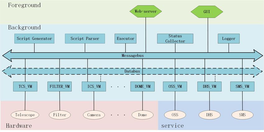
4                                               Z.Wang et al.

    The foreground handles the interaction between the telescope and the observer—it shows detailed in-
formation of each module of the telescope and generates observation control events and control commands
for the devices and services. Based on the control mode, it can be divided into local control and remote web
control.
    The background is the business logic center of the telescope observation control system, and it comprises
the following three modules. (a) Communication bus module: it transmits the control commands, status
information, and observation data between the modules. (b) Device module: a device directly controlled by
the UOCS during observation; it can be divided into various types, such as camera module, filter module,
optical system module, dome module, and the module for mounting telescope control (TCS). (c) Service
module: it provides the algorithms, logic control, and other services for the UOCS. According to the type of
service, service modules are classified into various types, including the observation target selection module,
script generation module, script parse module, command execution module, status collection module, and
site service module.

2.1 Communication protocol

The UOCS communication protocol can be divided into internal communication protocol and device com-
munication protocol. The device communication protocol varies for each device and is not discussed here.
In the initial stages of designing the internal communication protocol of the UOCS, we considered refer-
ring to the communication structure of RTS2 and using the classic TCP/IP protocol( Kubánek et al. 2006,
Kubánek et al. 2008). However, the complexity of the network structure worsens with the number of mod-
ules, which poses challenges to the development at the initial stages and maintenance at the later stages.
Thus, we used the XPUB/XSUB pattern of ZeroMQ to connect all modules of UOCS. Each module gener-
ates messages that represent its own status and sends them to the communication bus, and at the same time,
subscribes to the messages it needs to process from the communication bus.
    According to the data type and the required effectiveness, the communication bus can be divided into
two types: (a) message bus, which is used to transmit small amounts of data with high real-time perfor-
mance, such as control commands and device status; and (b) data bus, which is used to transmit large
amounts of data with low real-time performance, such as images and other data.
    Messages comprise a SenderID and message body, and it can be divided into three types depending on
the content of the message body: (a) command message, which is generated by the command executor and
user interface to control devices; (b) status message, which includes the status of command execution and
device information; and (c) event message, which is a real-time message generated by each module accord-
ing to the running condition—it is used to perform logical control of the modules and has a unidirectional
control flow.

2.2 Script generator and parser

Depending on the scientific objectives and observation procedures, the UOCS executes the control of mul-
tiple devices and service modules in serial, parallel, or serial–parallel combinations. Even for the same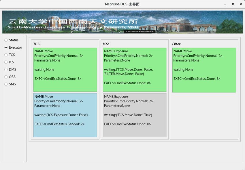
A Study on Universal Observation Control System And Its Application For LAMOST                5

objectives. An observation script is a configuration file that describes the execution sequence of each device
of the telescope; each observation task has a unique requirement, and all such requirements are realized by
configuring different observation script files. The details on the UOCS observation task are discussed later
in Section 4.2.2.

     Fig. 2 Parsing process of the observation script

   The observation script only describes the control logic of the observed devices, which cannot be con-
trolled directly. In the script parsing process (Figure 2), the scripts are first modified according to the ob-
served target, and then parsed into a command flow queue with the creation time as the unique identifier.
Each queue represents the command flow required by a device for sequential execution. For example, in the
“Move” command of TCS, “pre cmd=Telescope park” indicates that the “Move” command is executed fol-
lowing the “Park” command, and “next cmd=Camera Exposure” indicates that the “Exposure” command
of the camera is executed following the “Move” command.

2.3 Control command executor

The command executor is the core module of autonomous observation, and controls the execution sequence
of the devices based on the command flow generated by the script parser. The command executor consists
of a command flow queue, command task queue, and status monitoring module (Figure 3). The command
task queue holds the tasks that are being executed currently or about to be executed by each device, while
the status monitoring module receives the command execution status.
   During command execution, a command is first selected in order from the command flow queue of
the device list. If no dependent command is present or all commands in “pre cmd” have been executed, a
command task is created in the task queue, and the commands are sent to a virtual machine. Further, the
current task is suspended, awaiting resumption by the command execution status.
   The command execution status is generated by the device virtual machine in real time and indicates
the latest status of command execution. Figure 4 shows the binary command execution state code, which is
used to represent all states in a command execution.
   Figure 5 shows the transition diagram of finite state automation for command execution, which can
be used to monitor the command execution process. The initial state of each command is “Undo,” which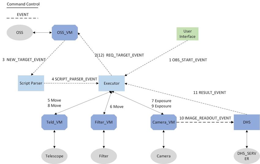
6                                               Z.Wang et al.

     Fig. 3 Schematic explaining the functions of the command executor

     Fig. 4 Binary command execution state code

command execution by the device, respectively. The exception handling process of command execution is
introduced later in Section 2.5.

     Fig. 5 State transition diagram of finite state automation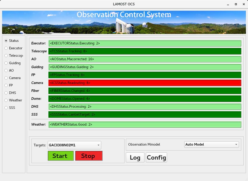
A Study on Universal Observation Control System And Its Application For LAMOST              7

   Upon receiving the command completion status, the status module resumes the waiting task, changes
the command state as “Done,” and executes the next executable command; this process is continued until
all commands in the command queue are executed.

2.4 Device virtual machine

The device virtual machine is an independent unit that is directly connected with the devices. It receives
commands and global status, converts the device control command format, distributes commands, generates
command execution statuses, analyzes device exceptions, generates abnormal events, and alarms the UOCS.
It is the core component of device control.
   Although the execution processes, methods, and communication protocols of the command differ with
each device, all undergo the four processes of translation, execution, monitoring, and logout. The “Device”
base class implements the basic control logic of the commands and provides various rewritable interfaces,
enabling the quick development of device virtual machines. For the connection mode of a device, it can be
dynamically modified through the configuration file.

     Fig. 6 Operation process of the device virtual machine

   Figure 6 shows the internal operational process of the device virtual machine. The virtual machine only
receives one command in the automatic observation mode, but receives multiple commands simultaneously
in the manual observation mode. The execution priority of commands could be low, medium, or high. For
example, if a new command has lower priority than the current command, the new command is moved to
the command queue. After the execution of the current command, the command with the highest priority
is obtained from the command queue. On the contrary, if the new command has higher priority than the
current command, the execution of the current command is stopped, and the new command is executed.
   During the operation of the virtual machine, the real-time status of the device is regularly queried by a
routine command, and then the running status and device status are sent to the status collector module. The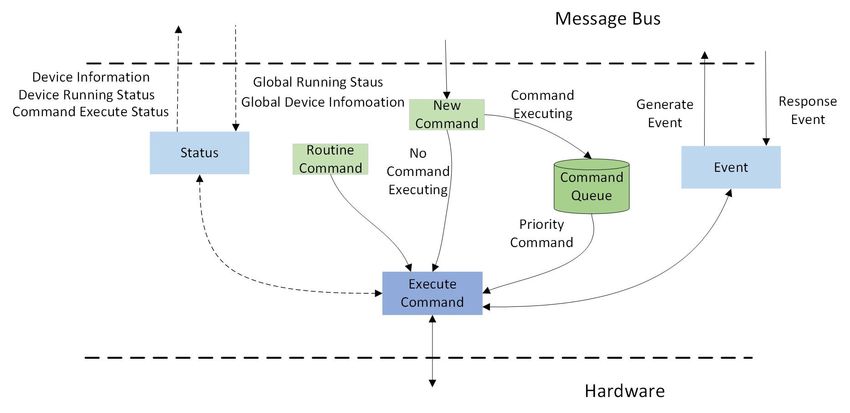
8                                               Z.Wang et al.

The device status represents the detailed information of the device. Each command execution is a separate
coroutine task. Figure 7 schematically describes the process of command execution in detail.

     Fig. 7 Command execution process of the device virtual machine

    Although the command executor can automatically control the execution sequence of the devices ac-
cording to the observation script, if the control logic is confused in the manual observation mode, observa-
tion errors could arise, affecting the observation efficiency. For example, in the camera exposure command,
if the TCS moves during camera exposure, the target image would be distorted.

    The global status is a set of running statuses of each module in the UOCS. The virtual machine de-
termines if the command can be executed according to the global status, prior to beginning the execution.
For example, the camera exposure command is executed only if the statuses of the TCS and the filter are
respectively “tracking” and “ready”. In the command execution process, the command execution state is
monitored based on the real-time status information of the device. In case exceptions occur, an exception
event is generated (discussed in the next subsection).

2.5 Exception handling mechanism

Depending on the producer, exceptions could be either device exceptions or internal exceptions. Device
exceptions are produced by the device module during command execution and are of three types: command
delete exception, command execution timeout exception, and command execution exception. Internal ex-
ceptions include memory leakage and other exceptions that occur during the module operation. Exceptions
are first attempted to be solved within the module; if this is unsuccessful, an exception event is generated
and sent to the message bus, which is captured by the user interface and alerted to the observer. The observer
will either ignore, re-execute, abandon, or suspend the observation depending on the content and level of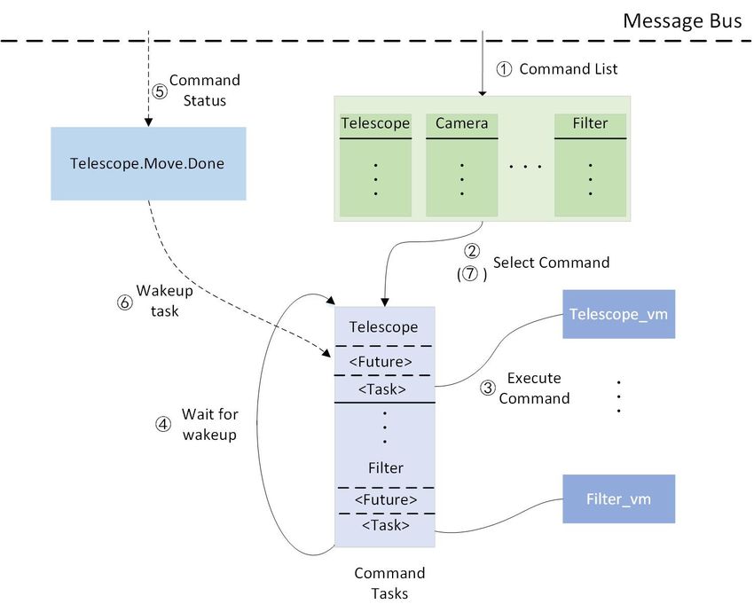
A Study on Universal Observation Control System And Its Application For LAMOST            9

2.6 Status collector

The status collection module collects, summarizes, collates, and distributes the status information of all
modules in the UOCS.

     Fig. 8 Process flow of status collection

   Although the device running statuses in the UOCS differ depending on their functions, they have the
same state characteristics. For example, all modules consist of an offline (VMExit) and waiting status
(ready). The running statuses of all modules are set to “VMExit” when the status collection module starts
and are updated and sent to the message bus in real time upon receiving the latest running status of each
module. When a module exits, the status collection module sets the module running status to “VMExit” and
generates a “module exit event” to notify all modules in the UOCS.

3 TESTING OF UOCS PERFORMANCE

Following the completion of the UOCS design, we deployed the UOCS in the LAMOST working environ-
ment for simulation observation. The UOCS server runs on four cores (including eight logical cores) and
has a memory of 32 GB. The device client simulates 50 devices through five computers, each running on
an Intel® Core™ i3-2100 Processor (clockspeed: 3.10 GHz) with 4 GB of memory. All computers were
connected through a 10 Gb switch and used the CentOS7 operating system. To verify if the performance
of the UOCS communication system can meet the requirements of astronomical observation and control, a
series of communication performance tests were conducted.

3.1 Performance of communication bus

3.1.1 Performance of message bus

The device client randomly generates data (8 B, 16 B...1 kB) composed of alphanumeric characters and
sends them to the message bus. The next data are sent after receiving the current data returned by the
message bus. To ensure measurement accuracy, each data unit is sent 1 000 000 times repeatedly; the test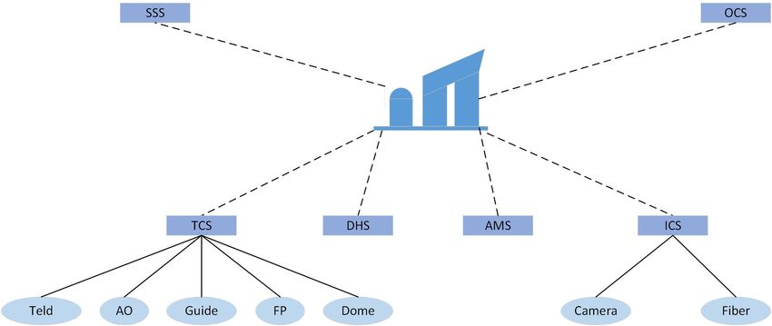
10                                              Z.Wang et al.

      Fig. 9 Transmission performance of the message bus for messages of different sizes

     The message bus takes 33 us on average to deliver the received message. Although the message delivery
time prolongs or shortens based on the data size, the difference is only ±5 us. The network bandwidth
increases the with increasing size of the message packets, reaching a maximum of 28 MB/s.

3.1.2 Performance of data bus

The device client randomly generates (1 MB, 8 MB...128 MB) image data and sends them to the data bus.
The next image is sent after receiving the data returned by the data bus.To ensure measurement accuracy,
each image is repeatedly sent 10 000 times; Figure 10 presents the test results.

      Fig. 10 Transmission performance of the data bus for images of different sizes

     As seen from the figure, the data delivery time increases with increasing size of the data packets. The
longest time of 1.75 s was required to deliver the data of size 128 MB. The network bandwidth reaches a
A Study on Universal Observation Control System And Its Application For LAMOST 11
phenomenon occurs because the internal cache of the data bus is full, resulting in a delay in forwarding the
data.
3.1.3 Influence of data bus on message bus
The data bus and message bus are two independent transmission modules. Nevertheless, when sharing the
same network hardware, they influence each other because of hardware resource contention. Figure 11
shows the impact of such a phenomenon on message delivery, when the data bus and message bus are
deployed on the same computer.
Fig. 11 Performance of message bus under different sizes of data transmitted by the data bus
For the image transmission on the data bus, compared with the independent transmission on the message
bus, the message delivery time increased 10-fold. The delivery time differed for images of different sizes.
For an image of size 1 MB, the message delivery time was approximately 200 us. The maximum delivery
time for a single message was approximately 500 us, for transmitting an image of size 128 MB.
3.2 Performance of status collector
The status collector receives and delivers the latest status information. Note that the integrity and real-time
collection of status information influence the stability of the entire system. The device client generates two
types of information about the detailed status and the running status of the device in a certain time interval
(1 ms, 2 ms... 10 ms), and it delivers the information to the status collector. The size of the running status
information of the device is fixed at 8 B, whereas that of the detailed status of the device differs, e.g., 8 B,
16 B...1 KB. Figure 12 shows the performance of the status collector at different status delivery intervals.
As shown in Figure 12, the packet loss is closely related to the status delivery interval and packet size.
If the delivery interval is 6 ms or longer, no packet loss occurs. However, if the interval is shorter than 6
ms, the packet loss rate increases with increasing packet size. The maximum packet loss rate of 63% occurs12 Z.Wang et al.
Fig. 12 Performance of the status collector at different status delivery intervals
The status collector collects the status information of only the subsystems and device control systems.
For example, the active optical control system of LAMOST sends only the current key information to the
status collector, and does not contain the real-time information of thousands of controllers. Furthermore,
the status transmission interval of the subsystems and the device control system is substantially longer than
the millisecond level, which is basically secondary. Therefore, the status collector of the UCOS fully meets
the demands of the current telescope for status collection.
4 APPLICATION OF UCOS TO LAMOST
During the first phase of survey of LAMOST (2011–2017), more than nine million low-resolution spectra
were obtained3 . At the beginning of the second phase, the medium-resolution survey was included, and
more than 2 million low-resolution spectra and medium-resolution spectra have been obtained since 201745 .
According to the observation plan, the plate will be exposed two or three times, with an exposure time of
20–30 min for low-resolution spectra and 10–20 min for medium-resolution spectra.
4.1 Observation flow of LAMOST
The LAMOST comprises several subsystems (Figure 13), including the data handling system (DHS), sur-
vey strategy system (SSS), telescope control system (TCS), instrument control system (ICS), auxiliary
monitoring system (AMS), and observation control system (OCS). The subsystems comprise one or sev-
eral systems or devices, which are independent of each other and deployed in different control computers.
For example, TCS consists of the mounting of telescope (Teld), focal plane (FP), dome, guiding system
(Guide), and active optics System (AO), among others. The ICS system includes the camera cluster control
system (Camera) and optical fiber control system (Fiber); the DHS processes the images obtained from
3 http://dr5.lamost.org/
4 http://www.lamost.org/dr8/A Study on Universal Observation Control System And Its Application For LAMOST 13
cameras(Luo et al. 2010). Plates are generated by SSS according to the sky survey and provided to as-
tronomers for selection. Each plate comprises several files, including those on the central star, guide star,
4000 targets, active optical parameters, and other observation information.
Fig. 13 LAMOST structure: subsystems and devices(DHS:Data Handling
System;AMS:Auxiliary Monitoring System;AO:Active Optics System;FP:Focal Plane;SSS:
Survey Strategy System;TELD:Telescope)
During observation, the LAMOST is operated in collaboration with the guide operator, Teld and FP
operators, AO operator, and ICS and DHS operators. Figure 14 shows the control flow of LAMOST ob-
servation. Each block represents an operation and contains information about the name, execution time,
and steps required to complete the operation. The horizontal operation is sequential, whereas the vertical
operation is a parallel operation.
Fig. 14 OCS Control Flow14 Z.Wang et al.
Before beginning the observation, the astronomer selects the required observation plate from the plate
list based on the meteorological conditions and observation plan, and notifies all the operators to commence
observation. Successively, the guide operator sends the plate information to all subsystems, following which
other operators perform corresponding operations, such as pointing of Teld toward a specific bright star,
moving away of FP, MB confocal, Teld pointing and tracking, FP moving back and tracking, MA correction,
guiding, MA re-correction, fiber moving and tracking, camera exposure, and image packaging. The time
required for a plate differs with the survey type. For example, in a medium-resolution survey, for two
exposures (wherein each exposure lasts 10 min), it is 61 min; for three exposures (wherein each exposure
lasts 20 min), it is 105.5 min. In a low-resolution survey, for two exposures (wherein each exposure lasts 20
min), it is 81 min; for three exposures (wherein each exposure lasts 30 min), it is 135.5 min. Furthermore,
regarding the number of operation steps for a plate, the operator requires 38 steps for two exposures, and
43 steps for three exposures. During observation, the operators orally update each other of the operation
progress, entailing 5% communication errors, which must be rectified by repeated confirmation by the
operators.
4.2 UOCS application to LAMOST
To ensure a stable and reliable observation of LAMOST, the UOCS is implemented in individual steps
according to the principle of “simple first, complex second.” First, the automated control between mod-
ules is achieved, which surmounts the communication obstacles between the subsystems and devices.
Subsequently, the interfaces of all subsystems and devices with UOCS are converted, ultimately realizing
automated observation control of the LAMOST.
4.2.1 Selection of communication bus
Currently, LAMOST comprises 10 devices or subsystems that must be connected with the UOCS. Among
these, 32 cameras are controlled by the camera control system( Tian et al.2018); each camera generates 32
MB-images, resulting in a total image size of 1024 MB. Recall from Figure 11 that for the data of size
32 MB transmitted by the data bus, the delivery time of the message bus is 300 ms, which fully meets the
requirement of the LAMOST in terms of the timeliness of observation and control. Therefore, in LAMOST,
we deploy the message bus and the data bus together in the UOCS server to reduce the complexity of the
system.
4.2.2 Control Flow of UOCS
The control flow of the UOCS observation script for LAMOST (Figure 15) is generated according to the
control sequence between the subsystems and devices by comprehensively analyzing the operation steps of
the operators. Unlike the centralized control mode for subsystems in OCS, UOCS is a distributed control
mode for devices. In the figure, blocks of each color represent a command to be executed by the device. The
script generator converts it into an XML file, while the script parser generates the control command stream.
Each block is a device control command containing the device name, command name, and parameters,A Study on Universal Observation Control System And Its Application For LAMOST 15
current command, whereas the pointing end represents the next command to be executed. A command list
represents a serial command queue, which contains the commands that are executed sequentially. Different
lists are parallel, which indicates that these commands can be executed simultaneously.
Fig. 15 Flowchart of LAMOST observation script
Figure 16 shows the control logic of UOCS observation, which is implemented via device commands
and event mechanisms. The dashed-line in the figure represents the event control flow between modules,
while the solid line represents the control flow between the command executor and devices or subsystems.
The OCS and other subsystems are developed by different units. Despite the existence of a unified com-
munication protocol, to realize automated control through UOCS, the control details of the subsystems and
devices must be first understood, and then a perfect exception handling and control mechanism must be
designed—this process requires a long time to study and prepare. The camera control system was main-
tained by the UOCS development team consisting of personnel familiar with the communication interface
and execution logic. The fiber control system contains fewer commands, a simple logic, and less manual
intervention. Therefore, automated control of these two subsystems of the UOCS was first realized; the
automated control of other subsystems and devices will be gradually realized in the future.
Because the internal communication protocol within UOCS differs between the camera and fiber con-16 Z.Wang et al.
Fig. 16 Control logic of LAMOST observation
Fig. 17 Device agent used to perform conversion for subsystems and devices
4.2.3 Camera agent
The camera agent involves four control commands: “Exposure,” “Abort,” “Pause,” and “Readout.” Each
command involves multiple operation steps. For example, “Exposure” requires four steps: “Ready,” “Setup
Parameters,” “Start Exposure,” and “Close.” In the UOCS observation script, the camera contains only one
command for control exposure. If the four-step control method is adopted, the control script of UOCS not
only becomes redundant, but also increases the complexity of the control logic of the command executor,
making the whole system unstable. Therefore, the exception handling and camera control tasks are assigned
to the camera agent in the UOCS. “Camera VM” is used to send a control command to the camera agent,
which divides the command into several sub-control commands according to the camera protocol and sends
them to all cameras. Additionally, the camera agent converts the cameras status into the internal deviceA Study on Universal Observation Control System And Its Application For LAMOST 17
4.2.4 Fiber agent
Fiber control involves three commands: “power-on,” “fiber movement,” and “power-off.” Upon receiving
the “start observation” command, the script parser loads the information of 4000 fibers as parameters into
the “Move” command, which is sent to “Fiber VM” by the command executor. Further, “Fiber Agent”
sends the above-mentioned three commands to the fiber control system.
4.2.5 Other subsystem agents
To ensure the implementation of the entire observation process in UOCS, the control commands for other
subsystems and devices are received by deploying a virtual machine in the control computer. The virtual
machine displays a dialog box with voice notification to prompt the operator to execute the corresponding
operation. Upon completing the execution, the operator selects “Done” or “Error” according to the operation
result and returns the command execution status to the executor.
Fig. 18 “Teld” virtual machine dialog box
4.3 Comparison of UOCS and OCS
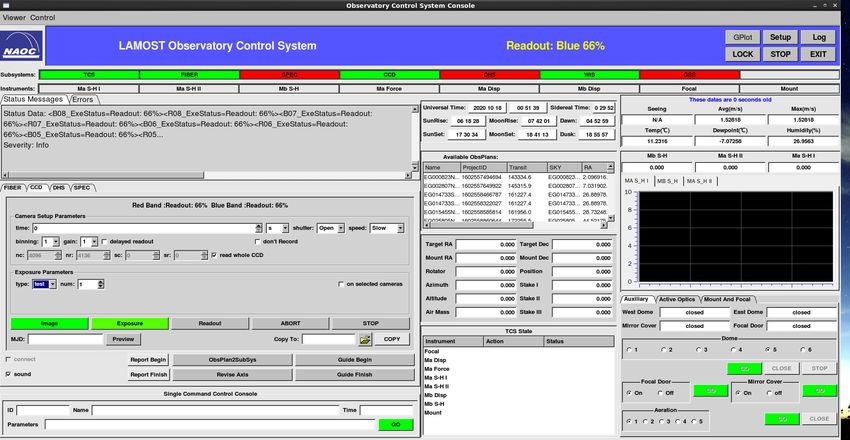
Figure 19 shows the control interfaces of the UOCS and OCS. In OCS (figure a), all information is displayed
in the same interface; therefore, details on the operation information of all devices or subsystems are not
available. For example, the information of only the overall progress of the cameras is displayed, while the
operation details of each camera are hidden. On the other hand, the UOCS (figure b) provides a dedicated
control and status display interface for each device.
Figure 20 shows the camera control interface of UOCS, which displays detailed information of 32
cameras during exposure. Compared with that of OCS, the layout of UOCS is more rational, and it more
clearly displays the running status of each module. Therefore, each device can be controlled independently,
greatly improving the convenience for operation control and debugging.
During observation, in the case of OCS, the astronomer selects a plate, informs the guide operator to
notify other operators of the observation target, and starts the next plate when all the images have been
packaged. Figure 21 shows the observation control flow of UOCS. The UOCS automatically sends it to all
devices or subsystems after the astronomer selects a plate; the next plate is started after the exposure of the
last image. Optimizing these two aspects can reduce 6.5 min for each plate, and decrease the number of
operation steps by 15 for two exposures and 19 for three exposures.
The UOCS performs significantly better than OCS in terms of the observation performance, operator18 Z.Wang et al.
(a) Control Interface of OCS
(b) Control Interface of UOCS
Fig. 19 Comparison of the control interfaces of UOCS and OCS
Fig. 20 Camera control interface of UOCS
a minimum of 6.8% and maximum of 10.6%, and that in low-resolution surveys improved by a minimum
of 4.8% and maximum of 6.2%. Further, the operational complexity of UOCS reduced by 39.4% for twoA Study on Universal Observation Control System And Its Application For LAMOST 19
Fig. 21 Observation control flow of UOCS for LAMOST
each other of the operation progress, because the operations required for the subsystems and devices are
automatically broadcasted through the UOCS system, thus avoiding the communication error of 5%.
5 SIMULATION OF MEPHISTO OBSERVATION CONTROL
The Multi-channel Photometric Survey Telescope (Mephisto) has a primary mirror of aperture 1.6 m, and
it is equipped with three high-precision charge-coupled device cameras( Li et al.2010). It can obtain data
amounting to 3.8 GB in a single exposure (nearly 6 TB of data per night) and transmits them to the data
center in real time. After online processing through DHS, if a transient source is found, all users are notified
via the internet. Additionally, Mephisto can stop observation of the current target and start observation of
an emergency target, accessed via internet.
Mephisto is aimed at obtaining the spectral data of billions of stars and galaxies, and millions of quasars
through a 10-year survey. To achieve this goal, Mephisto must operate efficiently and obtain the maximum
number of observation targets possible within a specified time. Thus, Mephisto has the characteristics of
short exposure, high switching frequency of observation targets, high data obtention rate, and a rich tele-
scope communication. Therefore, a stable, real-time, and rapid anomaly analysis and processing of the OCS
system are required.
The communication protocol and interface between the UOCS and various devices, and the observation
mode and strategy of the Mephisto are determined through several meetings and discussions. Figures 22
and 23 depict the observation script and control logic of the Mephisto based on UOCS. Differing from
LAMOST, every target of Mephisto is exposed twice using the same set of filters. The telescope needs to be
slightly adjusted after the first exposure, prior to beginning the second exposure. During the second image
readout, the UOCS control telescope points toward the next target, thus maximizing the observation time.
We built a virtual observation and test environment of Mephisto based on UOCS and began a series20 Z.Wang et al.
Fig. 22 Flow chart of Mephisto observation script
Fig. 23 Observation control logic of Mephisto
The green, blue, and gray blocks, respectively, indicate the commands that are completed, being executed,
and awaiting execution. To verify the exception handling ability of UOCS, so as to prepare for its later
application to Mephisto, we simulated various abnormal scenarios that could arise in various devices of
Mephisto, based on the maintenance experience gained from LAMOST.
6 FUTURE WORK
As for LAMOST, although the unified management of the device running status is realized through UOCS,
the communication obstacles between the devices and subsystems are eliminated, and the automatic obser-
vation process between the modules is completed preliminarily—this reduces the occurrence of observation
accidents caused by communication errors between observers. However, the automatic control of only the
camera cluster system and fiber system has been realized as of now, whereas the other devices and sub-
systems still require to be controlled manually via dialog-box prompts of UOCS. Therefore, longer strides
need to be made for a fully automated observation control of LAMOST. In the future, we plan to realize the
unified management of all devices and subsystems first, which can be controlled manually by the UOCS
to reduce the number of observers and operational steps. Subsequently, we will realize the fully automatedA Study on Universal Observation Control System And Its Application For LAMOST 21
Fig. 24 Execution of target observation in Mephisto
The development and construction of each device of Mephisto are progressing steadily. The UOCS will
complete offline simulations, start online testing of some devices, and perform a comprehensive system
debugging after the completion of telescope construction, ultimately realizing the automated observation
and control of Mephisto by 2021.
7 CONCLUSION
The UOCS uses multiple command queues to implement the serial and parallel controls of multiple devices
through observation scripts based on device commands. Further, it uses the event-driven messaging mecha-
nism to implement the control logic among the modules in the system. The device command control based
on the coroutine can dynamically adjust the command execution according to the priority of the commands.
The global state ensures the correct execution of mutually exclusive commands between the devices. The
concept of distributed control ensures the stable operation of the entire system to the maximum extent
possible.
Currently, UOCS has been implemented for the automated control of the camera cluster system and
fiber system of LAMOST. As of now, according to the control logic of Mephisto, the observation process
has been simulated. In the future, it will be used for the observation control of Mephisto.
Acknowledgements This study is supported by the National Natural Science Foundation of China (Grant
Nos. 11703044). The Guo Shou Jing Telescope ( the Large Sky Area Multi-Object Fiber Spectroscopic
Telescope, LAMOST) is a National Major Scientific Project built by the Chinese Academy of Sciences.
Funding for the project has been provided by the National Development and Reform Commission.
LAMOST is operated and managed by the National Astronomical Observatories, Chinese Academy of
Sciences. We also thank the reviewers for suggestions that improved the paper. The authors also gratefully22 Z.Wang et al. References Cui, X.-Q., Zhao, Y.-H., Chu, Y.-Q., et al. 2012, Research in Astronomy and Astrophysics, 12, 1197 Dworak, A., Ehm, F., Charrue, P., et al. 2012, JPhCS, 396, 012017 Kubánek, P., Jelı́nek, M., Vı́tek, S., et al. 2006, Proc. SPIE, 6274, 62741V Kubánek, P., Jelı́nek, M., French, J., et al. 2008, Proc. SPIE, 7019, 70192S Li, Z., Yuan, X., Zhang, K., et al. 2020, SPIE, 11203, 112030A Luo, A., Wu, K., Dong, J. 2010, SPIE, 7740, 774033 Sun S., Luo A. 2008, SPIE, 7019, 70192O Tian, Y., Wang, Z., Li, J., et al. 2018, RAA, 18, 054 Wang J.,Jin G.,Yu X.,et al. 2006,PIST, 8, 347 Zhao, Y. 2000, SPIE, 4010, 290 Zhao, Y. 2015, IAU General Assembly, 22, 2255903
You can also read