DeviceNet slave interface for digital multibus Mass Flow / Pressure instruments - Bronkhorst
←
→
Page content transcription
If your browser does not render page correctly, please read the page content below
Instruction manual

          DeviceNet™ slave interface
               for digital multibus
        Mass Flow / Pressure instruments

                              Doc. no.: 9.17.026X Date: 18-01-2018

                                        ATTENTION
Please read this instruction manual carefully before installing and operating the instrument.
Not following the guidelines could result in personal injury and/or damage to the equipment.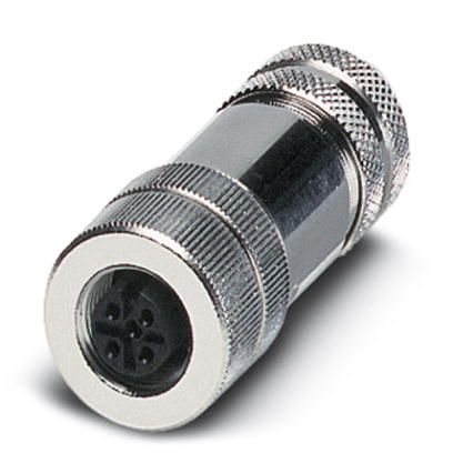
BRONKHORST®

Disclaimer
The information in this manual has been reviewed and is believed to be wholly reliable. No responsibility, however, is
assumed for inaccuracies. The material in this manual is for information purposes only.

Copyright
All rights reserved. This documentation is protected by copyright.
Subject to technical and optical changes as well as printing errors. The information contained in this document is
subject to change at any time without prior notification. Bronkhorst High‐Tech B.V. reserves the right to modify or
improve its products and modify the contents without being obliged to inform any particular persons or organizations.
The device specifications and the contents of the package may deviate from what is stated in this document.

Symbols

             Important information. Discarding this information could cause injuries to people or damage to the
             Instrument or installation.

             Helpful information. This information will facilitate the use of this instrument.

             Additional info available on the internet or from your local sales representative.

Warranty
Bronkhorst® products are warranted against defects in material and workmanship for a period of three years from the
date of shipment, provided they are used in accordance with the ordering specifications and the instructions in this
manual and that they are not subjected to abuse, physical damage or contamination.
Products that do not operate properly during this period may be repaired or replaced at no charge. Repairs are
normally warranted for one year or the balance of the original warranty, whichever is the longer.

          See also paragraph 9 of the Conditions of sales:
          http://www.bronkhorst.com/files/corporate_headquarters/sales_conditions/en_general_terms_of_sales.pdf

The warranty includes all initial and latent defects, random failures, and undeterminable internal causes.

It excludes failures and damage caused by the customer, such as contamination, improper electrical hook‐up, physical
shock etc.

Re‐conditioning of products primarily returned for warranty service that is partly or wholly judged non‐warranty may
be charged for.

Bronkhorst High‐Tech B.V. or affiliated company prepays outgoing freight charges when any party of the service is
performed under warranty, unless otherwise agreed upon beforehand. However, if the product has been returned
collect to our factory or service center, these costs are added to the repair invoice. Import and/or export charges,
foreign shipping methods/carriers are paid for by the customer.

Page 2                                                DeviceNet interface                                    9.17.026
BRONKHORST®

                                                              Table of contents
1      GENERAL PRODUCT INFORMATION .................................................................................................... 5
    1.1    INTRODUCTION ............................................................................................................................................. 5
    1.2    MULTIBUS TYPES ........................................................................................................................................... 5
    1.3    REFERENCES TO OTHER APPLICABLE DOCUMENTS ................................................................................................... 6
      1.3.1     Manuals and user guides: ........................................................................................................................... 6
      1.3.2     Technical Drawings: .................................................................................................................................... 6
      1.3.3     Software tooling: ........................................................................................................................................ 6
    1.4    SHORT FORM START‐UP................................................................................................................................... 7
2      FIELD BUS INSTALLATION ................................................................................................................... 8
    2.1        GENERAL ..................................................................................................................................................... 8
    2.2        DEVICENET CONNECTOR .................................................................................................................................. 8
    2.3        DEVICENET CABLES AND T‐PARTS ...................................................................................................................... 9
    2.4        MAXIMAL CABLE LENGTHS WITH DEVICENET ........................................................................................................ 9
    2.5        DROP LINES WITH DEVICENET ......................................................................................................................... 10
    2.6        NETWORK TERMINATION ............................................................................................................................... 10
    2.7        POWER SUPPLY........................................................................................................................................... 10
3      FUNCTIONAL DESCRIPTION .............................................................................................................. 12
    3.1    GENERAL ................................................................................................................................................... 12
    3.2    OBJECTS AND SERVICES ................................................................................................................................. 12
    3.3    EXPLICIT MESSAGING .................................................................................................................................... 12
      3.3.1     Identity Object........................................................................................................................................... 12
      3.3.2     DeviceNet Object ...................................................................................................................................... 13
      3.3.3     Connection Objects ................................................................................................................................... 13
      3.3.4     Supervisor Objects..................................................................................................................................... 14
      3.3.5     S‐Analog Sensor Object ............................................................................................................................. 15
      3.3.6     S‐Analog Actuator Object ......................................................................................................................... 16
      3.3.7     S‐Single Stage Controller Object ............................................................................................................... 17
      3.3.8     S‐Gas Calibration Object ........................................................................................................................... 18
      3.3.9     Elementary data Types ............................................................................................................................. 19
    3.4    POLLED I/O ............................................................................................................................................... 20
      3.4.1     Representation .......................................................................................................................................... 20
    3.5    DEVICE CONFIGURATION................................................................................................................................ 22
      3.5.1     Available data combinations for Polled I/O .............................................................................................. 22
      3.5.2     Available parameter data ......................................................................................................................... 22
4      OBJECT DESCRIPTION ....................................................................................................................... 23
    4.1    SUPERVISOR OBJECT ..................................................................................................................................... 23
      4.1.1     FLOW‐BUS interfacing (via RS232) ............................................................................................................ 23
      4.1.2     I/O assembly instances selection .............................................................................................................. 23
      4.1.3     Exception Status ........................................................................................................................................ 24
    4.2    SINGLE STAGE CONTROLLER ............................................................................................................................ 24
      4.2.1     Control mode ............................................................................................................................................ 24
      4.2.2     Setpoint ..................................................................................................................................................... 25
    4.3    ANALOG SENSOR OBJECT ............................................................................................................................... 26
      4.3.1     Sensor value .............................................................................................................................................. 26
      4.3.2     Alarm enable ............................................................................................................................................. 26
      4.3.3     Alarm Trip Points....................................................................................................................................... 26
      4.3.4     Gas calibration object instance ................................................................................................................. 26
    4.4    ANALOG ACTUATOR OBJECT INSTANCE .............................................................................................................. 26
      4.4.1     Actuator value........................................................................................................................................... 26
      4.4.2     Override .................................................................................................................................................... 27
      4.4.3     Safe state .................................................................................................................................................. 27
    4.5    GAS CALIBRATION OBJECT INSTANCE ................................................................................................................. 27
      4.5.1     Gas standard number ............................................................................................................................... 27
      4.5.2     Gas Symbol................................................................................................................................................ 27

Page 3                                                                         DeviceNet interface                                                            9.17.026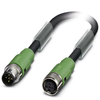
BRONKHORST®
4.6 NETWORK ERROR DETECTION.......................................................................................................................... 27
4.7 BUS DIAGNOSTICS ........................................................................................................................................ 28
4.8 SERIAL NUMBER .......................................................................................................................................... 29
5 EDS‐FILE ........................................................................................................................................... 30
6 ADD SLAVE TO DEVICENET................................................................................................................ 31
7 SLAVE CONFIGURATION SETTINGS ................................................................................................... 32
8 SLAVE PARAMETER SETTINGS ........................................................................................................... 33
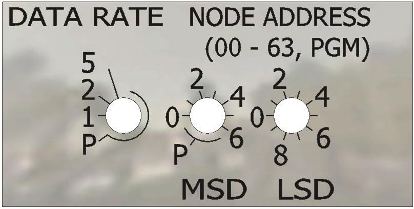
9 CHANGING MAC ID AND BAUD RATE ................................................................................................ 34
9.1 VIA ROTARY SWITCHES ON THE SIDE OF THE INSTRUMENT (IF PRESENT). ..................................................................... 34
9.1.1 DATA RATE ................................................................................................................................................ 34
9.1.2 NODE ADDRESS (00 – 63 PGM) ................................................................................................................. 34
9.2 VIA DEVICENET:.......................................................................................................................................... 35
9.2.1 MAC ID ...................................................................................................................................................... 35
9.2.2 BAUD Rate ................................................................................................................................................ 35
9.3 VIA RS232: FLOWFIX .................................................................................................................................. 36
9.4 VIA RS232: OTHER PROGRAMS ...................................................................................................................... 37
9.5 VIA MICRO‐SWITCH AND LEDS ON TOP OF INSTRUMENT ........................................................................................ 37
10 DOWNLOAD TO MASTER .............................................................................................................. 38
11 TEST COMMUNICATION ................................................................................................................ 40
12 TROUBLESHOOTING ...................................................................................................................... 41
12.1 LED INDICATIONS ........................................................................................................................................ 41
12.1.1 LED indications mode (MBC‐II and MBC3) ................................................................................................ 41
12.1.2 LED indications mode (MBC3 only) ........................................................................................................... 42
12.1.3 DeviceNet error description ...................................................................................................................... 43
12.2 TROUBLESHOOTING HINTS AND TIPS ................................................................................................................. 43
13 SERVICE ........................................................................................................................................ 44
Page 4 DeviceNet interface 9.17.026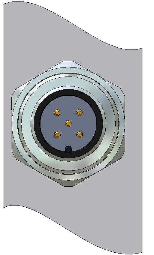
BRONKHORST®
1 GENERAL PRODUCT INFORMATION
1.1 INTRODUCTION
The DeviceNet interface offers a direct connection to
DeviceNet Networks for Bronkhorst® digital mass‐
flow/pressure meters/controllers according to the Mass
Flow Controller Profile specified by the ODVA. This
manual is limited to the description of the interface
between the DeviceNet Mass Flow Controller with a
master device.
This manual will explain how to install a Bronkhorst® instrument to your DeviceNet system. It only consists of that
information which is needed most.
There is no mutual communication between DeviceNet slaves, only between master and slave. Each slave should have
its own unique MAC ID on the network, otherwise there is no communication possible. Setting MAC ID can be
performed by either:
Master configuration software
Bronkhorst® tooling software: FlowFix (on Multibus documentation/software tool CD)
This programme is able to communicate with the instrument via RS232 using a special
cable. If you don’t have such a cable, ask your local sales representative.
Button (+ LED's) on top of the instrument
Rotary switches on the side of the instrument (if present).
Information about DeviceNet can be found at the website of de ODVA
organisation. www.odva.org
1.2 MULTIBUS TYPES
In 2000 Bronkhorst® developed their first digital instruments according to the “multibus” principle. The basic pc‐board
on the instrument contained all of the general functions needed for measurement and control, including alarm,
totalizing and diagnostic functions. It had analog I/O‐signals and also an RS232 connection as a standard feature. In
addition to this there is the possibility of integrating an interface board with DeviceNet™, Profibus DP, Modbus ,
FLOW‐BUS or EtherCAT protocol. The first generation (MBC‐I) was based on a 16 bit Fujitsu controller. It was
superseded in 2003 by the Multibus type 2 (MBC‐II). This version was also based on
the 16 bit Fujitsu controller but it had several improvements to the MBC‐I. One of
them is the current steering of the valve. It reduced heat production and improved
control characteristics. The latest version Multibus controller type 3 (MBC3) is
introduced in 2011. It is built around a 72MHz 32 bit NXP ARM controller. It has AD
and DA controllers on board which makes it possible to measure noise free and
control valves without delays. The internal control loop runs 6 times faster compared
to the MBC‐II therefore control stability has improved significantly. It also has several
improved functions like reverse voltage protection, inrush current limitation and
overvoltage protection.
MBC3 instruments can be recognised by the “MBC3” placed on lower left side
of the instrument label (see example).
Page 5 DeviceNet interface 9.17.026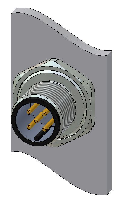
BRONKHORST®

1.3 REFERENCES TO OTHER APPLICABLE DOCUMENTS
Manuals and guides for digital instruments are modular. General instructions give information about the functioning
and installation of instruments. Operational instructions explain the use of the digital instruments features and
parameters. Field bus specific information explains the installation and use of the field bus installed on the
instrument.
1.3.1      Manuals and user guides:

                 General instructions                              Operational              Field bus specific
                Instrument type based                              instructions                information

 Document 9.17.022                                              Document 9.17.023              Document 9.17.024
                      Bronkhorst®
    General instructions digital Mass Flow / Pressure                                       FLOW‐BUS interface

 Document 9.17.031                                                                             Document 9.17.025
                        Bronkhorst®
              General instructions CORI‐FLOW                                              PROFIBUS DP interface

 Document 9.17.050                                                                             Document 9.17.026
                        Bronkhorst®
            General instructions mini CORI‐FLOW                Operational instructions     DeviceNet interface
                                                                 for digital multibus
 Document 9.17.044                                              Mass Flow / Pressure           Document 9.17.035
                         Bronkhorst®                                 instruments
         General instructions digital LIQUI‐FLOW L30                                         Modbus interface

                                                                                               Document 9.17.027
 Document 9.17.104 / 9.17.105
                       Bronkhorst®                                                          RS232 interface with
         Instruction manual MASS‐STREAM D‐6300                                              FLOW‐BUS protocol

                                                                                               Document 9.17.063
                                                                                             EtherCAT interface

                                                                                                Document 9.17.095
                                                                                             PROFINET interface

1.3.2      Technical Drawings:

Hook‐up diagram laboratory‐style MBC DeviceNet.pdf              (document 9.16.060)
Hook‐up diagram industrial style MBC DeviceNet.pdf              (document 9.16.054)
Hook‐up diagram CORI‐FLOW DeviceNet.pdf                         (document 9.16.050)
Hook‐up diagram LIQUI‐FLOW L30 digital DeviceNet.pdf            (document 9.16.071)

1.3.3      Software tooling:

Flowfix
FlowDDE
EDS file

               All these documents can be found at:
               http://www.bronkhorst.com/en/downloads

Page 6                                                  DeviceNet interface                            9.17.026
BRONKHORST®

1.4 SHORT FORM START‐UP
All necessary settings for this module are already performed at Bronkhorst®.
To follow next steps carefully is the quickest way to get this module operational in your own DeviceNet environment.

                  START

                 Master                   Make sure your master has been installed to the DeviceNet system
                 present

                Load EDS                  Load EDS‐file with configuration tool

                                          Bitmaps (with flow controllers) can be copied in the proper directory (mostly
              Copy bitmaps
                                          automatic, sometimes by hand; depends on program)

          Add slave to DeviceNet
                                          Select "Bronkhorst meter/controller" and add new instrument to the bus
                  system

         Set device configuration

            Set parameter data           Set parameter data for a‐cyclic setting of parameter values

                                         Default instruments will be delivered to customers on address 63 and with a
                                         baud rate of 125000 baud. Normally setting an address can be performed by
                                         your master configuration software.
         Set MAC ID and baud rate        However, if you choose to set a station address off‐line you can use the
              of instrument:             programme FLOWFIX to change MAC ID and baud rate via RS232
                                         connection. MAC ID and baud rate can also be changed by using the button
                                         on top of the instrument or the rotary switches on the side of the
                                         instrument if present. See chapter 8 for more details.

         Download configuration          Download all configuration settings into your master

                                         Test data‐exchange communication between your master and the
            Test data exchange
                                         instrument(s)

                  Ready

Page 7                                              DeviceNet interface                                  9.17.026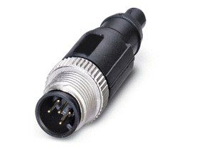
BRONKHORST®

2 FIELD BUS INSTALLATION
2.1 GENERAL
This chapter introduces the DeviceNet cable system and provides a brief overview of how to set up a DeviceNet
network efficiently. The steps in this chapter describe the basic tasks involved in setting up a network.

             For the installation of DeviceNet, ODVA has created document “DeviceNet Planning and Installation
             manual” which can be found at the website of de ODVA organisation.
             www.odva.org

2.2 DEVICENET CONNECTOR
Bronkhorst® instruments are fitted with a micro‐style sealed M12 connector.
                                                                                                   Wire     Usage
         M12 Connector                   Male                    Female            nr   Color
                                                                                                 Identity   Round

                                                                                   1    Bare      Drain     shield

                                                                                                    V+
                                                                                   2     RED                power
                                                                                                 (+24Vdc)
                                                                                                    V‐
                                                                                   3    Black               power
                                                                                                  (0Vdc)
                                                                                                 CAN_H
                                                                                   4    White                signal
                                                                                                 (CAN+)
                                                                                                  CAN_L
                                                                                   5     Blue                signal
                                                                                                  (CAN‐)

                                                                               5

                                                          4                                        3

                                                          1                                        2

                                                                  A‐coded

Page 8                                             DeviceNet interface                                 9.17.026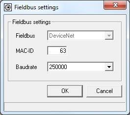
BRONKHORST®

2.3 DEVICENET CABLES AND T‐PARTS
                           M12 cable                                              M12 termination resistor

                              T‐part                                                    T‐part wiring

2.4 MAXIMAL CABLE LENGTHS WITH DEVICENET
The DeviceNet cable system uses a trunk/drop line topology

             Round shielded cable (thick, mid and thin) contains five wires: One twisted pair (red and black) for 24V
             dc power; one twisted pair (blue and white) for signal, and a drain wire (bare).
             Flat cable contains four wires: One pair (red and black) for 24 dc power; one pair (blue and white) for
             signal. Unshielded 4‐wire drop cable is only designed for use with flat cable systems.

Page 9                                               DeviceNet interface                                   9.17.026
BRONKHORST®
The distance between any two points must not exceed the maximum cable distance allowed for the data rate used.
Maximum distance Maximum distance Maximum distance Maximum distance
Data rate
(flat cable) (thick cable) (mid cable) (thin cable)
125k bit/s 420m 500m 300m 100m
250k bit/s 200m 250m 250m 100m
500k bit/s 75m 100m 100m 100m
The maximum cable distance is not necessarily the trunk length only. It is the maximum distance
between any two devices.
2.5 DROP LINES WITH DEVICENET
The cumulative drop line length refers to the sum of all drop lines, thick, thin, or mid cable, in the cable system. This
sum cannot exceed the maximum cumulative length allowed for the data rate used.
Data rate Cumulative drop line length
125k bit/s 156m
250k bit/s 78m
500k bit/s 39m
The maximum cable distance from any device on a branching drop line to the trunk line is 6m.
2.6 NETWORK TERMINATION
You must terminate the trunk line at both ends with 121 Ohms, 1%, 1/4W terminating resistors.
2.7 POWER SUPPLY
The cable system requires the power supply to have a rise time of less than 250 milliseconds to within 5% of its rated
output voltage. You should verify the following:
The power supply has its own current limit protection
Fuse protection is provided for each segment of the cable system
Any section leading away from a power supply must have protection
The power supply is sized correctly to provide each device with its
Required power
De‐rate the supply for temperature using the manufacturer’s guidelines
Use the power supply to power the DeviceNet cable system only. If a device requires a separate 24V
power source other than the DeviceNet power source, you should use an additional 24V power source.
Use only the BUS connector to power the device.
Powering from the BUS connector and Sub‐D9 (or 8 DIN) connector could damage the device.
Please refer the corresponding Bus Hook‐up manual for the right connections.
Page 10 DeviceNet interface 9.17.026BRONKHORST®
Choosing a Power Supply
The total of all of the following factors must not exceed 3.25% of the nominal 24V needed for a DeviceNet system.
initial power supply setting 1.00%
line regulation 0.30%
temperature drift (total) 0.60%
time drift 1.05%
load regulation 0.30%
Page 11 DeviceNet interface 9.17.026BRONKHORST®
3 FUNCTIONAL DESCRIPTION
3.1 GENERAL
The Bronkhorst® digital instruments will behave as slaves on the DeviceNet bus. This means all communication
(instructions / readout) will be performed by a master on the same DeviceNet field bus. Mostly this will be any PLC or
PC‐card controlling a process.
The Bronkhorst® DeviceNet MFC is a Group 2 Only Server device which messages comply with the CAN 2.0A standard
and with the DeviceNet protocol. The DeviceNet MFC supports two types of connection: Explicit and Polled I/O. As
defined by the DeviceNet protocol.
3.2 OBJECTS AND SERVICES
Bronkhorst® MFC’s consist of several objects with attributes and services for interfacing to DeviceNet. These objects
are described below.
The DeviceNet Mass Flow Controller will be in "Idle" state after powered on or reset. In this state, the device will not
allow the Master to use the Setpoint Attribute to control gas flow. Instead, gas flow will be controlled by the value
previously set in the Analog Actuator Object’s Safe‐State Attribute and Safe‐Value Attribute. For instance, if the Safe‐
State Attribute had a value 0x03 which is the code for “Use Safe Value” then the device will set the actuator (valve)
according to the value previously stored in the Analog Actuator Object’s Safe‐Value Attribute. To be able to control
the flow, the Master device must send a “Start” request to the supervisor object of the Mass Flow Controller. The
“Start” request brings the device from “Idle” state to “Executing” state. In this state, the device will be executing new
setpoints received from the Master and then control the flow accordingly. Another way to bring the device in the
"Executing" state is by sending I/O data (Polled I/O).
3.3 EXPLICIT MESSAGING
Using explicit messaging, following tables are needed with the descriptions of DeviceNet objects for Digital Mass Flow
/ Pressure Controllers / Meters. These messages have an a‐cyclic character. For cyclic messages, see Polled I/O in the
next paragraph.
The FLOW‐BUS column shows how DeviceNet attributes are mapped on the internal FLOW‐BUS
variables of the instrument. This information can be useful for who is familiar with FLOW‐BUS.
3.3.1 Identity Object
Class Code: 01 HEX
This object provides identification of and general information about the device. The Identity Object is present in all CIP
products.
IDENTITY OBJECT’S INSTANCE ATTRIBUTES (Instance = 1)
IDENTITY ATTRI‐ SERVICE FLOW‐
ATTRIBUTE NAME DATA TYPE Comment
OBJECT BUTE CODE BUS
0x01 0x01 Vendor Id 0x0E UINT 706
0x01 0x02 Device Type 0x0E UINT 0x001A
0x01 0x03 Product Code 0x0E UINT 113,12 IdentNr
0x01 0x04 Revision 0x0E STRUCT V major. minor
0x01 0x05 Status 0x0E WORD always 0x0001
0x01 0x06 Serial Number 0x0E UDINT calculate from 113,3
0x01 0x07 Product Name 0x0E SHORT‐STRING “Bronkhorst meter/controller”
Page 12 DeviceNet interface 9.17.026BRONKHORST®
IDENTITY OBJECT SERVICES
IDENTITY SERVICE
SERVICE NAME SERVICE DESCRIPTION
OBJECT CODE
0x01 0x05 Reset Reset device, parameters: 0 = reset, 1 = load default values + reset
0x01 0x0E Get_Attribute_Single Returns the contents of the specified attribute
0x01 0x10 Set_Attribute_Single Modifies an attribute value
3.3.2 DeviceNet Object
Class Code: 03 HEX
The DeviceNet Object provides the configuration and status of a DeviceNet port. Each DeviceNet product must
support (and anly one) DeviceNet object per physical connection to the DeviceNet communication link.
DEVICENET OBJECT’S INSTANCE ATTRIBUTES (Instance = 1)
DEVICENET ATTRI‐ SERVICE FLOW‐
ATTRIBUTE NAME DATA TYPE Comment
OBJECT BUTE CODE BUS
0x03 0x01 MAC ID 0x0E, 0x10 USINT 125,10 0‐63
0x03 0x02 BAUD Rate 0x0E, 0x10 USINT 126,9 0‐2
0x03 0x03 Bus Off Interrupt 0x0E, 0x10 BOOL 0,1
0x03 0x04 Bus Off Counter 0x0E, 0x10 USINT 0‐255
0x03 0x05 Allocation Information 0x0E STRUCT Alloc choice, Masters
MAC ID
DEVICENET OBJECT SERVICES
DEVICENET SERVICE
SERVICE NAME SERVICE DESCRIPTION
OBJECT CODE
0x03 0x0E Get_Attribute_Single Returns the contents of the specified attribute
0x03 0x10 Set_Attribute_Single Modifies an attribute value
0x03 0x4B Allocate M/S connection set Requests the use of the Predefined Master/Slave connection set
0x03 0x4C Release M/S connection set Release Master/Slave connection set
3.3.3 Connection Objects
Class Code: 05 HEX
Use the Connection Object to manage the characteristics of a communication connection.
CONNECTION OBJECT’S INSTANCE ATTRIBUTES (Instance = 1)
CONNECTION ATTRI‐ SERVICE FLOW‐
ATTRIBUTE NAME DATA TYPE Comment
OBJECT BUTE CODE BUS
0x05 0x01 State 0x0E USINT
0x05 0x02 Instance Type 0x0E USINT
0x05 0x03 Transport Class Trigger 0x0E BYTE
0x05 0x04 Produced Connection ID 0x0E UINT
0x05 0x05 Consumed Connection ID 0x0E UINT
0x05 0x06 Initial Comm. Characteristics 0x0E BYTE
0x05 0x07 Production Connection Size 0x0E UINT
0x05 0x08 Consumption Connection Size 0x0E UINT
0x05 0x09 Expected Packet Rate 0x0E,0x10 UINT
0x05 0x0C Watchdog Time out Action 0x0E,0x10 USINT
0x05 0x0D Produced Connection Path Length 0x0E UINT
0x05 0x0E Produced Connection Path 0x0E,0x10 EPATH
0x05 0x0F Consumed Connection Path Length 0x0E UINT
0x05 0x10 Consumed Connection Path 0x0E,0x10 EPATH
0x05 0x11 Production Inhibit Time 0x0E,0x10 UINT
CONNECTION OBJECT SERVICES
CONNECTION SERVICE
SERVICE NAME SERVICE DESCRIPTION
OBJECT CODE
0x05 0x05 Reset Used to reset all resetable Connection Objects
0x05 0x09 Delete Used to delete all Connection Objects and to release all associated resources
0x05 0x0E Get_Attribute_Single Returns the contents of the specified attribute
0x05 0x10 Set_Attribute_Single Modifies an attribute value
Page 13 DeviceNet interface 9.17.026BRONKHORST®
3.3.4 Supervisor Objects
Class Code 30 HEX
This object models the interface, functions and behaviour associated with the management of application objects for
devices within the “Hierarchy of Semiconductor Equipment Devices”
SUPERVISOR OBJECT’S INSTANCE ATTRIBUTES (Instance = 1)
DEVICE
ATTRI‐ SERVICE
SUPERVISOR ATTRIBUTE NAME DATA TYPE FLOW‐BUS Comment
BUTE CODE
OBJECT
0x30 0x01 Number of Attributes 0x0E USINT 20
0x30 0x02 Attribute List 0x0E Array of USINT
0x30 0x03 Manufacturer’s Device Type 0x0E SHORT‐STRING 113,1; Char[6] “MFM" or "MFC”
0x30 0x04 SEMI Standard Revision 0x0E SHORT‐STRING “E54‐0997”
0x30 0x05 Manufacturer’s Name 0x0E SHORT‐STRING “Bronkhorst High‐Tech”
0x30 0x06 Manufacturer’s Model # 0x0E SHORT‐STRING 113,2; Char[14]
0x30 0x07 Digital MFC Software Revision 0x0E SHORT‐STRING 113,5; Char[5] “V6.XX”
Level
0x30 0x08 DeviceNet Hardware Revision 0x0E SHORT‐STRING 113,7; Char[1] “C”
Level
0x30 0x09 Manufacturer’s Serial Number 0x0E SHORT‐STRING 113,3; Char[20] Unique serial nr. for BHT
instruments
0x30 0x0A Device Configuration 0x0E SHORT STRING 113,4; Char[16] Manufacturer configuration
0x30 0x0B Device Status 0x0E USINT
0x30 0x0C Exception Status 0x0E BYTE
0x30 0x0D Exception Detail Alarm 0x0E STRUCT
0x30 0x0E Exception Detail Warning 0x0E STRUCT
0x30 0x0F Alarm Enable 0x0E, 0x10 BOOL 0‐1
0x30 0x10 Warning Enable 0x0E, 0x10 BOOL 0‐1
0x30 0x13 Last Maintenance Date 0x0E DATE 113,11; Char[8] Service date
0x30 0x17 Running Hours 0x0E UDINT 118,2 0‐65535
0x30 0x64 Init Mode 0x0E, 0x10 USINT 0,10 0,64,73,82
0x30 0x65 Monitor 0x0E, 0x10 USINT 115,2 0: measure=setpoint
0x30 0x66 Default_Inp_IO_Assembly_Inst 0x0E, 0x10 USINT
0x30 0x67 Default_Outp_IO_Assembly_Inst 0x0E, 0x10 USINT
Device status
Attribute value State
0 Undefined
1 Self testing
2 Idle
3 Self test Exception
4 Executing
5 Abort
6 Critical fault
7‐50 Reserved by CIP
51‐99 Device specific
100‐255 Vendor specific
Exception Status
Exception status bit map, Bit 7 set to 0
Bit State
Function
0 Alarm/device‐common
1 Alarm/device‐specific
2 Alarm/manufacturer‐specific
3 Device specific definition reserved – set to 0
4 Warning/device‐common
5 Warning/device‐specific
6 Warning/manufacturer‐specific
7 0=basic method 1= Expanded Method
Page 14 DeviceNet interface 9.17.026BRONKHORST®
SUPERVISOR OBJECT SERVICES
SUPERVISOR SERVICE
SERVICE NAME SERVICE DESCRIPTION
OBJECT CODE
0x30 0x05 Reset Resets the device to the Self‐Testing state
0x30 0x06 Start Starts the device execution by moving the device to the Executing state
0x30 0x07 Stop Moves the device to the Idle state
0x30 0x0E Get_Attribute_Single Returns the contents of the specified attribute
0x30 0x10 Set_Attribute_Single Modifies an attribute value
0x30 0x4B Abort Moves the device to the Abort state
0x30 0x4C Recover Moves the device out of the Abort state
0x30 0x4E Perform_Diagnostics Causes the device to perform a set of diagnostic routines
3.3.5 S‐Analog Sensor Object
Class Code 31 HEX
The S‐Analog Sensor Objects models the acquisition of a reading from a physical sensor in a device.
ANALOG SENSOR OBJECT’S INSTANCE ATTRIBUTES (Instance = 1)
ANALOG ATTRI‐ SERVICE
ATTRIBUTE NAME DATA TYPE FLOW‐BUS Comment
SENSOR OBJECT BUTE CODE
0x31 0x01 Number of Attributes 0x0E USINT 12
0x31 0x02 Attribute List 0x0E Array of USINT
0x31 0x03 Data Type 0x0E, 0x10 USINT 0xC3=INT, 0xCA=REAL
0x31 0x04 Data Unit 0x0E, 0x10 UINT 0x1001=counts, 0x1400=sccm, etc
0x31 0x05 Reading Valid 0x0E BOOL 0 = invalid, 1 = valid
0x31 0x06 Sensor Value 0x0E INT or REAL1 1,0 see attribute 3 and 4
For data unit counts the value
attribute will be in the range of
0..32767 where:
0 = no flow/pressure
32000 = max flow /pressure (100.0%)
32767 = max flow /pressure (102.4%)
Note: 32767 is max. flow for data type
INT. Max. flow REAL = 41943.04
(131.07%)
0x31 0x07 Status 0x0E BYTE 1=High Alarm Exception,
2=Low Alarm Exception
0x31 0x08 Alarm Enable 0x0E, 0x10 BOOL
0x31 0x0A Full Scale 0x0E INT 32000
0x31 0x11 Alarm Trip Point High 0x0E, 0x10 INT 97,1 see attribute 3 and 4
0x31 0x12 Alarm Trip Point Low 0x0E, 0x10 INT 97,2 see attribute 3 and 4
0x31 0x14 Alarm Settling Time 0x0E, 0x10 UINT 97,7 0‐65000, alarm delay (msec)
0x31 0x1C Autozero status 0x0E UINT 1 = busy, 0 = ready
0x31 0x23 Gas Calibration Object 0x0E, 0x10 UINT 1‐8
Instance 1 = fluid 1 selected
0x31 0x69 Temperature 0x0E REAL 33,7 Actual fluid Temperature (mini Cori)
0x31 0x6A Density 0x0E REAL 116.15 Actual fluid Density (mini Cori)
0x31 0x6B Counter Value 0x0E, 0x10 REAL 104, 1 Actual counter value
0x31 0x6C Counter Unit Index 0x0E, 0x10 USINT 104, 2 Index of counter unit table
0x31 0x6D Counter Limit 0x0E, 0x10 REAL 104, 3 Counter lImit
0x31 0x6E Counter Setpoint 0x0E, 0x10 USINT 104, 5 0 = No setpoint change
mode 1 = Setpoint change on limit reached
0x31 0x6F Counter Setpoint 0x0E, 0x10 UINT 104, 6 Setpoint when counter limit reached
0..32000 where
0 = 0% and 32000 = 100%
0x31 0x70 Counter Unit 0x0E STRING 104, 7 Counter unit string
0x31 0x71 Counter Mode 0x0E, 0x10 USINT 104, 8 0 = Counter Off
1 = Counter On
2 = Counter On, Up to limit
0x31 0x72 Counter Reset Mode 0x0E, 0x10 USINT 104, 9 Counter reset mode (see manual)
Page 15 DeviceNet interface 9.17.026BRONKHORST®
0x31 0x73 Counter Convergence 0x0E, 0x10 REAL 104, 10 0.0 …. 1.0
factor (mini CORI‐FLOW only)
0x31 0x74 Counter Controller 0x0E, 0x10 REAL 104, 11 (mini CORI‐FLOW only)
Gain
0x31 0x75 Reset 0x10 USINT 115, 8 0 = No Action
1 = Reset counter
3 = Reset counter
4 = Reset and stop counter
1
Depends on the value assigned to the Data Type attribute. If the value of this attribute is 0xC3, the
selected data type is Integer. If the value of this attribute is 0xCA, the selected data type will be the
IEEE‐754 single‐precision floating‐point.
No indication is available if counter limit is reached.
A workaround could be:
read counter limit and counter value all the time by the master application.
If counter value >= counter limit, the batch has been reached.
ANALOG SENSOR OBJECT SERVICES
ANALOG SENSOR OBJECT SERVICE CODE SERVICE NAME SERVICE DESCRIPTION
0x31 0x0E Get_Attribute_Single Returns the contents of the specified attribute
0x31 0x10 Set_Attribute_Single Modifies an attribute value
0x31 0x4B Zero Adjust Start Autozero
3.3.6 S‐Analog Actuator Object
Class Code 32 HEX
The S‐Analog Actuator Object models the interface to a physical actuator in a device.
ANALOG ACTUATOR OBJECT’S INSTANCE ATTRIBUTES (Instance = 1)
ANALOG
ATTRI‐ SERVICE FLOW‐
ACTUATOR ATTRIBUTE NAME DATA TYPE Comment
BUTE CODE BUS
OBJECT
0x32 0x01 Number of Attributes 0x0E USINT 7
0x32 0x02 Attribute List 0x0E Array of USINT
0x32 0x03 Data Type 0x0E, 0x10 USINT 0xC3=INT, 0xCA=REAL
0x32 0x04 Data Units 0x0E, 0x10 UINT 0x1001 = counts, 0x1007 = %
0x32 0x05 Override 0x0E, 0x10 USINT
0x32 0x06 Actuator Value (valve) 0x0E, 0x10 INT or REAL1 114,1 See attribute 3 and 4 For data unit
counts the value attribute will be in the
range of 0..32767.
Where: 0 = valve closed
32767 = valve fully open
0x32 0x07 Status 0x0E BYTE always 0
0x32 0x15 Safe State 0x0E, 0x10 USINT
0x32 0x16 Safe Value 0x0E, 0x10 INT 114,6
1
Depends on the value assigned to the Data Type attribute. If the value of this attribute is 0xC3, the
selected data type is Integer, and if the value of this attribute is 0xCA, the selected data type will be the
IEEE‐754 single‐precision floating‐point.
ANALOG ACTUATOR OBJECT SERVICES
ANALOG ACTUATOR OBJECT SERVICE CODE SERVICE NAME SERVICE DESCRIPTION
0x32 0x0E Get_Attribute_Single Returns the contents of the specified attribute
0x32 0x10 Set_Attribute_Single Modifies an attribute value
Page 16 DeviceNet interface 9.17.026BRONKHORST®
3.3.7 S‐Single Stage Controller Object
Class Code 33 HEX
The S‐Single Stage Controller Object models a closed‐loop control system within a device.
CONTROLLER OBJECT’S INSTANCE ATTRIBUTES (Instance = 1)
SINGLE STAGE
ATTRI‐ SERVICE FLOW‐
CONTROLLER ATTRIBUTE NAME DATA TYPE Comment
BUTE CODE BUS
OBJECT
0x33 0x01 Number of 0x0E USINT 6
Attributes
0x33 0x02 Attribute List 0x0E Array of USINT
0x33 0x03 Data Type 0x0E, 0x10 USINT 0xC3=INT, 0xCA=REAL
0x33 0x04 Data Units 0x0E, 0x10 UINT 0x1001=counts, 0x1400=sccm, etc
0x33 0x05 Control Mode 0x0E, 0x10 USINT
0x33 0x06 Setpoint 0x0E, 0x10 INT or REAL1 1,1 See attribute 3 and 4. For data unit
counts the setpoint attribute must be in
the range of 0..32000.
Where: 0 = min. setpoint (0%)
32000 = max. setpoint (100%)
0x33 0x0A Status 0x0E BYTE
0x33 0x13 Ramp Rate 0x0E, 0x10 UDINT 1,2 Setpoint slope in msec
(max. 3000000 msec)
1
Depends on the value assigned to the Data Type attribute. If the value of this attribute is 0xC3, the
selected data type is Integer, and if the value of this attribute is 0xCA, the selected data type will be the
IEEE‐754 single‐precision floating‐point.
Page 17 DeviceNet interface 9.17.026BRONKHORST®
CONTROLLER OBJECT SERVICES
SINGLE STAGE
SERVICE
CONTROLLER SERVICE NAME SERVICE DESCRIPTION
CODE
OBJECT
0x33 0x0E Get_Attribute_Single Returns the contents of the specified attribute
0x33 0x10 Set_Attribute_Single Modifies an attribute value
3.3.8 S‐Gas Calibration Object
Class Code 34 HEX
An S‐Gas Calibration Object affects the behaviour of an associated S‐Analog Sensor object instance.
GAS CALIBRATION OBJECT’S CLASS ATTRIBUTES (Instance = 0)
GAS
ATTRI‐ FLOW‐
CALIBRATION ATTRIBUTE NAME SERVICE CODE DATA TYPE Comment
BUTE BUS
OBJECT
0x34 0x02 Max Instance1 0x0E UINT 8
1
This is the total number of process gases currently calibrated for the device.
GAS CALIBRATION OBJECT’S INSTANCE ATTRIBUTES (Instance = 1...8)
GAS
ATTRI‐ SERVICE
CALIBRATION ATTRIBUTE NAME DATA TYPE FLOW‐BUS Comment
BUTE CODE
OBJECT
0x34 0x01 Number of attributes 0x0E USINT 6
0x34 0x02 Attribute List 0x0E Array of USINT
0x34 0x03 Gas Standard number 0x0E UINT see list from SEMI
0x34 0x04 Valid Sensor instance 0x0E UINT 1
0x34 0x05 Gas Symbol 0x0E SHORT STRING 1,17; Char[10] fluidname
0x34 0x06 Full Scale 0x0E STRUCT Full scale capacity (REAL),
capacity unit (UINT)
0x34 0x08 Calibration Date 0x0E DATE 113,9; Char[8]
1
The gas calibration is formed by a 3rd grade polynomial (y=a+bx+cx²+dx³). This polynomial will perform
linearization to achieve the wanted accuracy. Up to 8 polynomials can be stored for different fluids.
Each fluid has its own instance (1...8).
GAS CALIBRATION OBJECT SERVICES
GAS
CALIBRATION SERVICE CODE SERVICE NAME SERVICE DESCRIPTION
OBJECT
0x34 0x0E Get_Attribute_Single Returns the contents of the specified attribute
0x34 0x10 Set_Attribute_Single Modifies an attribute value
Page 18 DeviceNet interface 9.17.026BRONKHORST®
3.3.9 Elementary data Types
This section describes the data type specification syntaxes, data type value ranges and operations that can be
performed on the defined data types.
Table 2‐18: SUBSET OF ELEMENTARY DATA TYPES
Keyword Description Minimum range Maximum range
BOOL Boolean 0 1
SINT Short Integer ‐128 127
INT Integer ‐32768 32767
USINT Unsigned Short Integer 0 255
UINT Unsigned Integer 0 65535
UDINT Unsigned Double Integer 0 2^32‐1
REAL Floating Point IEEE 754 single floating point
DATE Date only D#1972‐01‐01 D#2151‐06‐06 (65536 days)
BYTE Bit string – 8 bits
WORD Bit string – 16 bits
STRING Character string (1 byte per character) See IEC1131‐3
SHORT_STRING Character string (1 byte per character, See IEC1131‐3
1 byte length indicator)
Page 19 DeviceNet interface 9.17.026BRONKHORST®
3.4 POLLED I/O
3.4.1 Representation
All of the above attributes in the tables from Table 2‐1 to Table 2‐16 can be accessed using Explicit Messaging. Upon
existence of an explicit connection, a Polled I/O connection can also be established and coexist. Once the Polled I/O
connection has been established, the device will be able to accept and process the Polled I/O requests. For example, if
Instance #7 has been selected as Output IO Assembly Instance, two data bytes representing the new setpoint shall be
appended to the Polled I/O request for setting a setpoint. If the Data Unit attribute were 0x1001 as the code for
“Counts”, the value of the setpoint bytes will be an signed integer where 0x7D00 (*) represents 100% flow and 0x0000
represents 0% flow. Upon reception of the Polled I/O Request, if Instance #2 has been selected as Input IO Assembly
Instance the DeviceNet MFC will respond with a Polled I/O Response carrying with it three data bytes as described
below:
Polled I/O Response’s Data Field using Counts as Data Unit
Byte0: Byte1: Byte2:
Exception Status Indicated Flow (LSB) Indicated Flow (MSB)
BYTE INT (0x7D00 = 100%)
Polled I/O Request’s Data Field using Counts as Data Unit
Byte0: Byte1:
New Setpoint (LSB) New Setpoint (MSB)
INT (0x7D00 = 100%)
Note that if “Counts” has been selected for the Data Unit attribute of the Analog Sensor and Controller object (i.e., the
value of these attributes is 0x1001), then the Indicated‐Flow bytes in the Polled I/O Response represent the same
information as that of the New‐Setpoint bytes in the Polled I/O Request (i.e., 0x0000 represents 0% flow and 0x7D00
(*) represents 100% flow). However, if the “Data Unit” attribute of the Sensor and the Setpoint object are 0x1400, the
value of the indicated flow and setpoint will be in Standard Cubic Centimeter (SCCM). Note that the setpoint and the
indicated flow can be set with different data unit (i.e., Counts for Setpoint and SCCM for Indicated‐flow or vice versa).
Since the Indicated‐flow and Setpoint attribute are integer, if used in SCCM mode the value of these attribute can not
exceed 32767 SCCM. Therefore the SCCM mode shall not be used for MFCs having gases with the full‐scale exceeding
32767 SCCM or having the Full‐scale loaded with SLM data unit.
Polled I/O Response’s Data Field using SCCM as Data Unit
Byte0: Byte1: Byte2:
Exception Status Indicated Flow (LSB) Indicated Flow (MSB)
BYTE INT (0 to Full Scale)
Polled I/O Request’s Data Field using SCCM as Data Unit
Byte0: Byte1:
New Setpoint (LSB) New Setpoint (MSB)
INT (0 to Full Scale)
The tables above show some examples of the Polled I/O setting. There are eight (8) IO Assembly Instances that the
user can choose from; 4 for input and 4 for output. These instances are specified in the MFC Device Profile document.
See next paragraph for more details.
(*) 100% Measured Value indication for Bronkhorst® instruments is 0x7D00 (signed integer). Maximum
value for Measured Value is 102.4 %, which is: 0x7FFF. Other suppliers may use different ranges for
Measured Value. Via Full Scale: attribute 0x0A of object 0x31, analog sensor, it is possible to readout
the signed integer value used for 100%.
Page 20 DeviceNet interface 9.17.026BRONKHORST®
Furthermore, with the use of the Data‐type attribute(0x03) and Data‐unit attribute(0x04) of the Sensor object 0x31
and the Controller object 0x33 the user can select one of the following settings for both Explicit and Polled I/O
messages (see paragraph 3.2.2 for a complete list of supported data‐units, the settings below are just a few
examples):
Example 1 (ClassId: 0x31, Data‐type: 0xC3, Data‐unit: 0x01 0x10): Signed Integer Count Indicated‐flow.
Example 2 (ClassId: 0x31, Data‐type: 0xC3, Data‐unit: 0x00 0x14): Signed Integer SCCM Indicated‐flow.
Example 3 (ClassId: 0x31, Data‐type: 0xCA, Data‐unit: 0x01 0x10): Single‐precision floating‐point Count Indicated‐flow.
Example 4 (ClassId: 0x31, Data‐type: 0xCA, Data‐unit: 0x00 0x14): Single‐precision floating‐point SCCM Indicated‐flow.
Example 5 (ClassId: 0x33, Data‐type: 0xC3, Data‐unit: 0x01 0x10): Signed Integer Count Setpoint.
Example 6 (ClassId: 0x33, Data‐type: 0xC3, Data‐unit: 0x00 0x14): Signed Integer SCCM Setpoint.
Example 7 (ClassId: 0x33, Data‐type: 0xCA, Data‐unit: 0x01 0x10): Single‐precision floating‐point Count Setpoint.
Example 8 (ClassId: 0x33, Data‐type: 0xCA, Data‐unit: 0x00 0x14): Single‐precision floating‐point SCCM Setpoint.
For Polled I/O messages only Data‐type can be selected. The Data‐unit attribute will be automatically set when Polled
I/O is started (on receipt of the first Polled I/O Request’s Data). The Data‐unit setting will be determined by the
selected IO Assembly Instance (see paragraph 2.5.1, Available data combinations for Polled I/O).
The Data‐type and Data‐unit Attribute can only be set when the MFC is in the Idle state. If the MFC is
not in this state (i.e., Executing state) the user must use the Stop service (0x07) of Instance (0x01) of the
Supervisor object (0x30) to allow the MFC to enter the Idle state for making the change. When the
attribute has been set the user can use the Start service (0x06) of the same object and instance to
resume the Executing state.
Example 1: How to program instrument with option 1 from above
Object Instance Service code Attribute Value Description
30 1 0x07 stop: instrument to idle state;
green LED long flash: 2 sec on, 0.1 sec off
31 1 0x10 0x03 0xC3 Data type = INT
31 1 0x10 0x04 0x01 0x10 Data unit = COUNT
30 1 0x06 start: instrument to executing state green LED on
continuously
Example 2: How to program instrument with option 8 from above
Object Instance Service code Attribute Value Description
30 1 0x07 stop: instrument to idle state;
green LED short flash: 2 sec on, 0.1 sec off
33 1 0x10 0x03 0xCA Data type = REAL
33 1 0x10 0x04 0x00 0x14 Data unit = SCCM
30 1 0x06 start: instrument to executing state green LED on
continuously
Page 21 DeviceNet interface 9.17.026BRONKHORST®
3.5 DEVICE CONFIGURATION
3.5.1 Available data combinations for Polled I/O
Using the EDS‐file in the DeviceNet configuration program of the master, following I/O combinations are available (IO
Assembly Instances):
Inputs:
1. ExceptionStatus + Flow data‐type: integer (0xC3)
2. ExceptionsStatus + Flow + Setp + Override + Valve signal data‐type: integer (0xC3)
3. ExceptionStatus + Flow data‐type: float (0xCA)
4. ExceptionsStatus + Flow + Setpoint + Override + Valve data‐type: float (0xCA)
Outputs:
1. Setpoint data‐type: integer (0xC3)
2. Override + Setpoint data‐type: integer (0xC3)
3. Setpoint data‐type: float (0xCA)
4. Override + Setpoint data‐type: float (0xCA)
3.5.2 Available parameter data
Using the EDS‐file in the configuration program of the master, following parameters are available for customising:
1. Polled I/O (input) : select IO Assembly Instance for input (data combination polled I/O)
2. Polled I/O (output) : select IO Assembly Instance for output (data comb. polled I/O)
3. Control mode : sets controller to idle, valve off, purge or normal setpoint
4. Setpoint ramp rate (msec) : sets ramp rate of setpoint from 0…3000000 msec
5. Fluid number : selects wanted calibration/fluid nr.: 1…8
6. Alarm : switches alarms on or off
7. Alarm delay (msec) : sets alarm delay time in range 0…65000 msec
Parameter "Polled I/O (input)" and "Polled I/O (output)" must always be set to the correct value. This
will select the data combination for Polled I/O (IO Assembly Instance). If it is not possible to start
communication with the device always check these two settings!
Page 22 DeviceNet interface 9.17.026BRONKHORST®
4 OBJECT DESCRIPTION
4.1 SUPERVISOR OBJECT
4.1.1 FLOW‐BUS interfacing (via RS232)
To enable controlling the device by RS232, a new control mode has been added: CTRL_RS232 (18). This control mode
is equal to CTRL_FB (0), but in this case the device will always make the transition to the EXECUTING state (no start
request or receipt of I/O data needed). So CTRL_RS232 makes it possible to give setpoints without the need of a
DeviceNet connection.
The device will only be compliant with the ODVA profile when control mode is CTRL_FB (0).
In case of taking over control via RS232, it is possible to send value 18 to parameter “Control Mode” (FLOW‐BUS:
proc1, par4 or FLOWDDE: parameter 12). From this moment on, it will be possible to give setpoints without being
overruled by the safe state. This control mode will be valid until the next power‐up situation. Control mode = 18 will
not be stored into non‐volatile memory. At each power‐up, the instrument will be normally set to control mode = 0.
The safe state is active when the device is not in the EXECUTING state.
The functionality of the RS232 FLOW‐BUS “Control Mode” parameter is not the same as the Control
Mode attribute in the Single State Controller Object (attribute 0x05, object 0x33).
4.1.2 I/O assembly instances selection
Attribute 0x66 and 0x67 can be used to select the I/O assembly instances used for the Polled I/O connection (see also
Polled I/O input/output parameters in EDS file).
Devicenet Input I/O assembly
obj 0x30, attr 102 instance
0 2
1 6
2 14
3 18
Devicenet Output I/O assembly
obj 0x30, attr 103 instance
0 7
1 8
2 19
3 20
Page 23 DeviceNet interface 9.17.026BRONKHORST®
4.1.3 Exception Status
Exception status is a single byte which indicates the status of alarms and warnings. When 128 is read everything is o.k.
This means that the expanded method is used for the exception status.
Bit Meaning
0 alarm device common
1 alarm device specific
2 alarm manufacturer specific
3 reserved
4 warning device common
5 warning device specific
6 warning manufacturer specific
7 1 = expanded method
For more details, see the DeviceNet specification.
4.2 SINGLE STAGE CONTROLLER
4.2.1 Control mode
The Control Mode is implemented as follows:
Control Mode Setpoint Value
0 (Normal) set by attribute 6 (setpoint)
1 (Close) 0
2 (Open) max. value
3 (Hold) last used value
4 (Safe state) (not supported)
When Override attribute of Analog actuator (object 0x32, attribute 0x05) is set to a value other than 0, this attribute
will override the Control Mode attribute.
Page 24 DeviceNet interface 9.17.026BRONKHORST®
4.2.2 Setpoint
For the objects Analog Sensor and Single Stage Controller, the following data types and data units are supported for
Value and alarm levels. Note that data type and data unit can only be changed when not in executing mode. The
followings data units are supported (dependent on sensor type, actual sensor type can be found in calibration sheet):
Sensortype Supported units
0 (pressure) 0x1001 (counts)
0x1007 (percentage) [not for Sensor value]
0x1300 (psi)
0x1301 (Torr)
0x1303 (mm Hg)
0x1305 (cm H2O)
0x1307 (bar)
0x1308 (mbar)
0x1309 (Pa)
0x130A (kPa)
0x130B (atm)
0x130C (gf/cm2)
0x0800 (cm Hg)
0x0801(kgf/cm2)
1 (liq. Volume) 0x1001 (counts)
0x1007 (percentage) [not for Sensor value]
0x0900 (l/min)
0x0901 (ml/h)
0x0902 (ml/min)
0x0903 (l/h)
3
0x0904 (mm /s)
3
0x0905 (cm /min)
2 (mass flow) 0x1001 (counts)
0x1007 (percentage) [not for Sensor value]
0x1404 (kg/s)
0x140E (mg/min)
0x140F (g/min)
0x1410 (kg/h)
0x0A00 (kg/min)
0x0A01 (g/h)
0x0A02 (g/s)
0x0A03 (mg/h)
0x0A04 (mg/s)
3 (gas volume) 0x1001 (counts)
0x1007 (percentage) [not for Sensor value]
0x1400 (sccm)
0x1401 (slm)
0x0B00 (ln/min)
0x0B01 (mln/h)
0x0B02 (mln/min)
0x0B03 (ln/h)
3
0x0B04 (m n/h)
0x0B05 (mls/min)
0x0B06 (mls/h)
0x0B07 (ls/h)
3
0x0B08 (m s/h)
0x0B09 (ls/min)
4 (other) 0x1001 (counts)
0x1007 (percentage) [not for Sensor value]
5 (temperature) 0x1001 (counts)
0x1007 (percentage) [not for Sensor value]
0x1200 (deg. C)
0x1201 (deg. F)
0x1202 (K)
The following data types are supported: 0xC3 (int) 0xCA (real)
Page 25 DeviceNet interface 9.17.026BRONKHORST®
4.3 ANALOG SENSOR OBJECT
4.3.1 Sensor value
See Setpoint attribute of Single stage controller above.
4.3.2 Alarm enable
Attribute Alarm enable of Analog Sensor object is linked to propar 97;3 (Alarmmode).
FLOW‐BUS Devicenet
Alarmmode Alarm enable
proc 97; par 3 obj 0x31, attr 8
ALRM_OFF 0 (off)
(ALRM_RESPONSE)
(ALRM_POWERFAILURE)
ALRM_MINMAX 1 (on)
When 0 is written to Alarm enable attribute, the internal alarm mode is always set to ALRM_OFF. The modes
ALRM_RESPONSE and ALRM_POWERFAILURE can be set by RS232, not by DeviceNet.
More information can be found in the manual “917023 Operational instructions digital instruments”
This document can be found at:
http://www.bronkhorst.com/en/downloads/instruction_manuals/
4.3.3 Alarm Trip Points
Alarm_Trip_Point_Low attribute is linked to propar 97/2 (Min. limit). Valid range is [0, 32000].
Alarm_Trip_Point_High attribute is linked to propar 97/1 (Max. limit). Valid range is [0, 32000].
A value outside the valid range is rounded to the nearest value within the range. Note that the Trip Point values are
dependent on the selected data types/units.
For the maximum value the following mapping is used:
FLOW‐BUS DeviceNet
Max limit Alarm Trip Point High
proc 97; par 1 obj 0x31, attr 17
0 (off) 32000
1 0
32000 31999
4.3.4 Gas calibration object instance
Indicates which Gas Calibration object instance is active for this object. The value of this attribute is equal to
(fluidnumer+1). Value 0 (disabled) is not supported.
4.4 ANALOG ACTUATOR OBJECT INSTANCE
4.4.1 Actuator value
The followings data units are supported:
0x1001 (counts): 0 = valve closed, 32767 = valve fully open
0x1007 (percent): 0 = valve closed, 100 = valve fully open
The following data types are supported: 0xC3 (int) 0xCA (real)
Page 26 DeviceNet interface 9.17.026You can also read