Manual PLP-REM-300 - Duratech
←
→
Page content transcription
If your browser does not render page correctly, please read the page content below
Manual
              English....................Page 3
PLP-REM-300   Nederlands.......Pagina 21
              Français...............Page 39
              Deutsch...............Seite 57
              Español.............Página 75
2
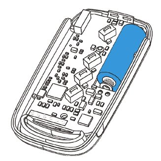
Table of contents

                                                                                                                      ENG
Technical specifications
         General Specifications ........................................................... Page 4
         PLP-REM-300 overview......................................................... Page 4
         Logic board .............................................................................. Page 5
Installation Instructions
         Single PLP-REM-300 unit ..................................................... Page 6
         Multiple PLP-REM-300 installation...................................... Page 7
Operation modes .................................................................................. Page 8
DIP switch functionalities .................................................................... Page 9
Transmitter functions
         Operation mode: PLC ............................................................ Page 10
         Operatio mode: ON/OFF........................................................ Page 10
         Replacing transmitter keypad ............................................... Page 11
         Pairing the handheld transmitter ......................................... Page 11
DMX 512 communication
         Single PLP-REM-300 unit ..................................................... Page 12
         Multiple PLP-REM-300 installation ..................................... Page 13
RS-485 communication
         Single PLP-REM-300 unit ..................................................... Page 14
RS-485 command set........................................................................... Page 15
RESET procedure ................................................................................... Page 16
Troubleshooting ..................................................................................... Page 17
Transmitter battery................................................................................. Page 17
Pool light wiring instructions .............................................................. Page 18
Wiring remark ......................................................................................... Page 20

                                                                                                                  3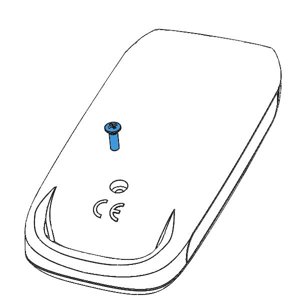
Technical specifications

General specifications

Input Voltage: 			              230 VAC 50Hz
Output Voltage:		               12 VAC
Transformer VA rating:		        350VA
Max output Power:		             300 VA (12 VAC / 25A)
Max rating relay contact A &B   16A / 250 VAC
Max switching power A & B       4000VA
RF band			                      868 MHz
Ambient Air Temperature:        0°C to +40°C
Humidity			                     10% to 90% RH - non condensing
Ingress protection rate:		      IP54
IEC Protection Class:		         Class II

PLP-REM-300 overview

12 VAC
Transformer
Integrated toroïdal                                              Logic board
Transformer 350VA                                                For details:
                                                                 see next page

                                                                 12VAC connection
Circuit breakers                                                 terminals
                                                                 To connect the pool
                                                                 lights

4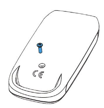
Logic board

                                                                                                                 ENG
     DMX Address dial       DIP switch                                   DuraLink RF board
     To choose the          To select controller functionalities         For wireless communication
     DMX start address

                                         (1)                       DuraLink

                                         (2)
                                                                                          Pairing / RESET
                                                                                          button

                                                                                          Ethernet port
                                                                                          For future use

                                                                                          SD card slot
                                                                                          For firmware updates

                                               (4)     (5)
                                                             (6)                          CAN bus
                                                                                          For future use
              (3)

                                                                                          RS-485
                                                          (7)
                                                                                          connection
                                                                                          To connect to
                                                                      (8)                 home automation
                                                                                          system
                                                                                          (see page 14)

      12VAC connection                   A/B output                   DMX input/outpout
      terminals                          For auxiliary circuits       The PLP-REM can act
      To connect the pool                Acts as a SPST               as a DMX receiver with
      lights                             (single-pole, single-        DMX passthrough
                                         throw) switch

Status LED’s:
(1) General status                                                   (5) Switch B status (Green = ON)
    Green = OK                                                       (6) CAN status
    Red = error overvoltage or overcurrent                           (7) RS-485 signal
(2) Pairing / RESET status                                           (8) DMX signal
(3) 12VAC to Pool lamps (Green = ON)
(4) Switch A (Green = ON)

                                                                                                            5
Installation Instructions

Single PLP-REM-300 unit

. Connect a 230VAC power source to the 230VAC terminals of the
    PLP-REM-300. Connect the pool lights to the 12VAC connection terminal
    block in the PLP-REM-300.
. The PLP-REM-300 has a 300VA transformer built in. The total power load
    of pool lights can not exceed this.

                                                           Connect the pool
                                                           lights to the 12VAC
     Connect the                                           terminals
     230VAC power
     source to the
     circuit breaker

                          230VAC

6
ENG
Multiple PLP-REM-300 installation
For extended installations with many pool lights (hotels, commercial instal-
lations,...), it might be necessary to use multiple PLP-REM-300’s.
In this case, the remote needs to be paired with all PLP-REM-300’s, to en-
sure a perfect synchronisation of all pool lights.
To do this, simply follow the pairing procedure on page 11, and repeat this
for all PLP-REM-300’s in the installation.
230VAC
230VAC
230VAC
7Operation Modes
The PLP-REM-300 controller has 2 main operation modes:
“ON/OFF control mode” & “PLC control mode”. Each mode has it’s own
functionalities:
ON/OFF PLC
Compatible lamps
Switch lamps ON/OFF YES YES
Change lamp color YES(1) YES(1)
Operate Relay A & B YES YES
Dimming lamps NO YES(1)
DMX control NO YES
RS-485 control YES (2)
YES
Dip switch setting DIP 1 ON DIP 1 OFF
Remote keypad type(3)
1) Only for RGB lamps
2) In ON/OFF control mode, only a few RS-485 commands are available (see p 16)
3) Depending on which control mode is selected, the keypad of the transmitter needs
to be changed
8DIP switch functionalities
ENG
The DIP switch on the main circuit board of the PLP-REM-300 allows the
user to customise the way the PLP-REM-300 operates.
CAUTION: Always switch off the main power supply to the
PLP-REM-300 before changing the DIP switches
ON position
OFF position
DIP SWITCH
function setting 1 2 3 4 5 6
ON/OFF ON
Operation Mode
PLC OFF
PULSE mode ON
Relay A
TOGGLE mode OFF
PULSE mode ON
Relay B
TOGGLE mode OFF
FAST ON
Fast DMX setting *
STANDARD OFF
NO LOOP ON
DMX
LOOP OFF
SLAVE ON
MASTER/SLAVE mode
MASTER OFF
* Fast DMX setting
Only for Adagio Pro lamps from 2018 and on
9Transmitter functions
OPERATION MODE: PLC (default mode)
Short push (< 1 sec):
Toggle all lamps ON or OFF (1)
Long push (> 2 sec(2)):
(1)
All lamps & “12VAC TO LAMPS” relay are turned OFF
Short push:
Go to next color program
Long push:
Toggle output A ON/OFF
Short push:
Go to the previous color program
Long push:
Toggle output B ON/OFF
Short push:
Select next dimming level:
100% -- 50% -- 25% ---> 100% -- ...
Long push:
Set lamps to Program 1 (blue) & full brightness
OPERATION MODE: ON/OFF
Short push (< 1 sec):
Toggle all lamps ON or OFF
Short push:
Go to next color program
Long push:
Auto sync procedure (3)
Short push:
Toggle output A ON/OFF
Long push:
/
Short push:
Toggle output B ON/OFF
Long push:
/
(1) Lamp ON or OFF status is memorized after power down
(2) The green LED in the transmitter will light up as soon as you start pressing a button, and will stop
after 2 seconds, so you know exactly when to release the button.
(3) The lamps will be turned off for 30 seconds and then switched ON/OFF 3 times. This will set all
lamps to program 1: blue
10Replacing transmitter Keypad
ENG
Depending on which control mode is selected, the keypad of the transmitter
needs to be changed:
• Remove the philips head screw and open the transmitter
• Replace the Keypad in the top part of the transmitter housing
• Reassemble in reverse order
Keypad for
PLC mode
Keypad for
ON/OFF mode
Pairing the handheld remote to the PLP-REM-300
All handheld transmitters are already paired in the factory and ready to use. In
case a problem arises, the pairing process can be done as below:
1) Press the pairing button on the circuit board, inside the PLP-REM-300
---> The BLUE LED will start to blink
2) Within 25 seconds, push any button on the handheld transmitter.
---> If the remote is paired correctly, the BLUE LED will flash slowly for 5 times
---> UNPAIRING:
See RESET procedure: page 16
DuraLink
Pairing Indicator LED
Pairing button
(blue)
11DMX 512 communication
Single PLP-REM-300 unit
1) Make sure DIP switch 1 is switched OFF.
2) Make sure the lights are turned ON with the remote first.
DMX PANEL
Address dial
Connect DMX
panel
to DMX IN (+/-)
230VAC
Address dial setup
Setting the DMX address of the PLP-REM-300:
Select the desired number on the address dial. The chosen number deter-
mines the DMX addresses of the PLP-REM-300 & lamps.
Each lamp uses 3 bytes of DMX data (R-G-B), and all lamps receive the same
DMX data from the PLP-REM-300.
Address dial
position 0 1 2 ...
R G B R G B R G B ...
DMX
1 2 3 4 5 6 7 8 9 ...
address
The DMX start address can be overruled by using the RS-485 command:
“set DMX start address” (see page 15)
12ENG
Multiple PLP-REM-300 installation
1) Connect the DMX panel to the “DMX IN” port of the first PLP-REM-300
2) Connect the PLP-REM-300’s with each other (open loop):
DMX OUT --> DMX IN (polarized terminals + -)
3) Set the DMX address for each PLP-REM-300 via the address dial.
- Option 1: All PLP-REM-300’s can be set to the same address:
This implies that all lamps will receive the same DMX data,
And will all operate identically
- Option 2:PLP-REM-300’s can be set to different addresses:
Each PLP-REM-300 will have it’s own group of connected lamps
that will operate identically.
However, since each PLP-REM-300 has it’s own unique address,
the different lamp groups can be controlled separately
DMX PANEL
Address dial Address dial Address dial
230VAC 230VAC 230VAC
13RS-485 communication
Single PLP-REM-300 unit
1) Make sure DIP switch 1 is switched OFF.
2) Make sure the lights are turned ON with the remote first.
3)Connect the RS-485 source to the “485” port on the PLP-REM-300
4) Communication settings: 9600, 8, 1, n
5) Command list: see page 15
RS-485 Source
230VAC
14available in available in
Command Command Remark Example ON/OFF mode PLC mode
Lamps OFF PL0 All lamps OFF X X
Lamps ON PL1 All lamps ON X X
Program UP PsU Jump to next program X X
Program Down PsD Return to previous program X
xx is the decimal representation
Set Program PSxx PS06 = jump to program 6 X
of the program number (01 - 14)
Auto sync procedure PsS executes the auto sync procedure (see page 10) X X
White 1 PW1 Jump to White 1 (program 12) X
White 2 PW2 Jump to White 2 (program 13) X
RS-485 Command set
White 3 PW3 Jump to White 3 (program 14) X
1) PC255128064 = Full output level on Red color, half out-
rrr, ggg and bbb are the decimal representation put level on Green color, 1/4 output level on Blue color
Set RGB PCrrrgggbbb X
of the RGB value (with leading zero’s) 2) PC255255255 = All colors at full output level
3) PC000000000 = All colors OFF
set the OUTPUT value of the lamp in % (000 -
Set Dim value PDxxx PD075 = 75% output level (on all LED’s) X
100)
PA035E = set DMX start address to 35 [35(R), 36(G),
set DMX startAdress PAxxxyz y = ‘e’ or ‘E’ X
37(B)]
Set color in percentage Pprgbe variable size, rgb = ASCII 0-255, e = end character Pp25050100e = Red 25%, Green 50%, Blue 100% X
Set color in hex Pcrgbe variable size, rgb = ASCII 0-255, e = end character Pc64128255e = Red 25%, Green 50%, Blue 100% X
x = 1 (ON), 0 (OFF), P (Pulse) !this overrules
Relay A control PRAx PRA1 = Relay A ON PRA0 = Relay A OFF X X
dipswitch
x = 1 (ON), 0 (OFF), P (Pulse) !this overrules
Relay B control PRBx PRB1 = Relay B ON PRB0 = Relay B OFF X X
dipswitch
ON/OFF relay control PRMx x = 1 (ON), 0 (OFF) PRM1 = Relay ON/OFF control ON X X
PT035 = Set white color temperature to 3500K (in steps
Color temperature PTxyz x = ten thousand ; y = thousand ; z = hundred X
15
of 500K)
ENGRESET procedure
RESET procedure for the control board
1) Make sure the PLP-REM-300 is powered ON
2) Press and hold the RESET button on the logic board
3) The blue LED will light up
4) Release the RESET button when the blue LED turns off
The control board has been RESET.
!
And all transmitters have been unpaired.
DuraLink
Blue
LED
RESET
button
16ENG
Troubleshooting
PROBLEM SOLUTION
The PLP-REM doesn’t react to • Perform a RESET procedure
transmitter commands • Check the battery of the handheld
transmitter (see below)
• The transmitter is not paired-
correctly with the PLP-REM.
Repeat the pairing process
• Reduce the distance between
handheld transmitter and PLP-REM
and/or remove obstacles
• Check the General status light on
the logic board. If it’s red, then
the secondary voltage is too high
(>14VAC) or there is a short circuit
The pool lights don’t work • Perform a RESET procedure
or don’t change colors • Check if all connections are made
correclty according to the electrical scheme.
• Switch the PLP-REM-300 to ON/
OFF mode (DIP switch nr 1) and
check if the lamps work
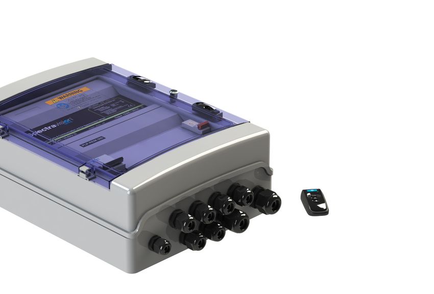
Transmitter battery
Check battery status:
Push and release any button on the remote. The green LED should still
light up 0,5 second after you released. If the LED stops faster, then the
battery needs to be replaced
Replacing transmitter battery:
• Remove the philips head screw and open the transmitter
• Replace the battery, respecting the polarity
Battery type: A23 12V
+
-
17Pool light wiring instructions
Each lamp is connected to the transformer by a separate cable
(Preferred for new installations)
Pool
Pool
house
SELECT
CABLE SECTION & MAXIMUM LENGTH
4m cable included in lamp package
Separate cable ( not included ) ! Always use a toroïdal transformer
18ENG
SELECT
CABLE SECTION & MAXIMUM LENGTH
VA TRANSFORMER
LAMP TYPE 1,5mm2 2,5mm2 4,0mm2 6,0mm2 10mm2
(12VAC)*
PLP050-WH
PLP050-WW 122m 204m 326m 490m 820m 8 VA
PLP050-BL
PLP050-RGB/TW 79m 132m 212m 318m 530m 12 VA
PLP100-WH
PLP100-WW 26m 43m 69m 104m 173m 32 VA
PLP100-BL
PLP100-RGB/TW 15m 25m 41m 61m 100m 48 VA
PLP170-WH
PLP170-WW 11m 19m 30m 46m 75m 66 VA
PLP170-BL
PLP170-RGB/TW 8m 14m 23m 35m 57m 80 VA
MAXIMUM AND STABLE LIGHT OUTPUT IS ONLY GUARANTEED WHEN
THE INSTALLED CABLE CROSS SECTION MATCHES OR EXCEEDS THE
ADVISED VALUES IN THE ABOVE TABLE
* The transformer VA rating must be greater or equal to the sum of VA ratings of
all connected lamps.
These cable lenghts are calculated with worst case voltage drops in the
electrical wiring.
19Wiring remark
Third party equipment such as frequency inverters and electric motors can
generate excessive noise on the 230VAC / 400VAC power line.
This noise might be injected into the adjacent 12VAC power line and dis-
turb the power line communication towards the AdagioPro RGB lights.
To prevent this, please take care of the following:
Keep 230VAC / 400VAC power line cables at least 50cm separated
! over their full length from the 12VAC power line towards any RGB
lights
Do not mix 12VAC and 230VAC / 400VAC power line cables into the
! same cable trays
Pool
Pool
house
12VAC to lamps
(**)
230VAC Min. 50cm
230VAC / 400VAC to third party equipment
(**) Do not mix 12VAC and 230VAC / 400VAC power line cables into the
same cable trays
20Inhoudstafel
Technische specificaties
Algemene Specificaties .......................................................... Pagina 22
PLP-REM-300 overzicht ........................................................ Pagina 22
Controller board...................................................................... Pagina 23
Installatie Instructies
Enkele PLP-REM-300 unit..................................................... Pagina 24
Installatie met meerdere PLP-REM-300’s.......................... Pagina 25
NL
Werkingsmodus ..................................................................................... Pagina 26
DIP schakelaar functies ........................................................................ Pagina 27
Afstandsbediening functies
Werkingsmodus: PLC.............................................................. Pagina 28
Werkingsmodus: AAN/UIT..................................................... Pagina 28
Klavier van afstandsbediening vervangen .......................... Pagina 29
Afstandsbediening en controller koppelen........................ Pagina 29
DMX 512 communicatie
Enkele PLP-REM-300 unit..................................................... Pagina 30
Installatie met meerdere PLP-REM-300’s.......................... Pagina 31
RS-485 communication
Enkele PLP-REM-300 unit..................................................... Pagina 32
RS-485 commando’s ............................................................................ Pagina 33
RESET procedure ................................................................................... Pagina 34
Probleemoplossing................................................................................ Pagina 35
Afstandsbediening batterij.................................................................... Pagina 35
Kabelinstructies ..................................................................................... Pagina 36
Kablering opmerking............................................................................. Pagina 38
21Technische specificaties
Algemene specificaties
Ingangsspanning: 230 VAC 50Hz
Uitgangsspanning: 12,5 VAC
Transformator vermogen: 350VA
Max uitgangsvermogen: 300 VA (12 VAC / 25A)
Max stroom relais contact A &B 16A / 250 VAC
Max schakel vermogen A & B 4000VA
RF band 868 MHz
Omgevingstemperatuur: 0°C to +40°C
Vochtigheidsgraad: 10% to 90% RH - non condensing
IP code: IP54
IEC beschermingsklasse: Class II
PLP-REM-300 overzicht
12 VAC
Transformator
Geïntegreerde Controller board
ringkern Voor details:
transformator 350VA zie volgende pagina
12VAC Aansluiting
Zekeringen Om de zwembad-
verlichting op aan te
sluiten
22Controller board
DMX adres toewijzer DIP schakelaar DuraLink RF board
Om het DMX start adres Om de controller functies te Voor draadloze communicatie
te kiezen selecteren
DuraLink
(2)
RESET KNOP
NL
Ethernet poort
Voor toekomstig
gebruik
SD card slot
Voor firmware updates
(4) (5) CAN bus
(6) Voor toekomstig
(3) gebruik
RS-485
(7)
connectie
Om te verbinden met
(8) domotica systemen
(zie pagina 14)
12VAC aansluitklemmen A/B uitgang DMX ingang/uitgang
Om de zwembadverlichting Voor additionele circuits. De PLP-REM kan werken als DMX
op aan te sluiten Gedraagt zich als een SPST ontvanger (met DMX doorgang-
(sinlge-pole, single-throw) signaal)
schakelcontact
Status LED’s:
(1) Algemene status (5) Schakelcontact B status
Groen = OK (Groen = AAN)
Rood = overvoltage of overcurrent (6) CAN status
(2) RESET status (7) RS-485 signaal
(3) 12VAC naar zwembadverlichting (8) DMX signaal
(Groen = AAN)
(4) Schakelcontact A (Groen = AAN)
23Installatie instructies
Enkele PLP-REM-300 unit
. Verbind de 230VAC aansluiting van de PLA-REM-300 met de netspanning
Verbind de zwembadverlichting met de 12VAC aansluiting van de
PLP-REM-300.
. The PLP-REM-300 heeft een ingebouwde 300VA transformator. Het totale
vermogen van de zwembadverlichting mag dit niet overschrijden.
Kijk in de handleiding van het gekozen type zwembadverlichting
! om te weten hoeveel VA elke lamp nodig heeft.
Verbind de zwembad-
verlichting met de
12VAC klemmen
Verbind de 230V
netstpanning
met de zekering
230VAC
24Installatie met meerdere PLP-REM-300’s
Voor uitgebreide installaties met veel lampen (hotels, commerciele installat-
ies,...), kan het noodzakelijk zijn om meerdere PLP-REM-300’s te gebruiken.
In dit geval moet de afstandsbediening gekoppeld zijn met alle PLP-REM-
300’s om een perfecte synchronisatie van de lampen te bekomen.
Om dit te doen: volg je koppel procedure op pagina 29, en herhaal deze
NL
voor alle PLP-REM-300’s in de installatie
230VAC
230VAC
230VAC
25Werkingsmodus
De PLP-REM-300 kan gebruikt worden in 2 hoofd werkingsmodi:
“AAN/UIT bedieningsmodus” & “PLC bedieningsmodus”. Elke modus heeft
een aantal specifieke functies:
AAN/UIT PLC
Compatibele lampen
schakel lampen AAN/UIT JA JA
Verander kleur van lamp JA(1) JA(1)
Bedien Relais A & B JA JA
Dimmen van de lampen NEE JA(1)
DMX sturing NEE JA
RS-485 sturing JA (2)
JA
Dip switch positie DIP 1 AAN DIP 1 UIT
Type klavier
afstandsbediening(3)
1) Enkel voor RGB lampen
2) In AAN/UIT bedieningsmodus zijn slechts enkele RS-485 commando’s beschikbaar
(zie p 33)
3) Afhankelijk van de gekozen werkingsmodus, moet het rubber klaviertje van de
afstandsbediening verwisseld worden (meegeleverd in verpakking).
26DIP switch functies
De DIP switch op het moederbord van de PLP-REM-300 laat toe om een
aantal functies van de PLP-REM-300 aan te passen:
WAARSCHUWING: Zorg ervoor dat de voedingsspanning van de
PLP-REM-300 uitgeschakeld is, vooraleer de DIP
switches te veranderen
NL
AAN positie
UIT positie
DIP SWITCH
functie setting 1 2 3 4 5 6
AAN/UIT AAN
Werkingsmodus
PLC UIT
PULS modus AAN
Relais A
TOGGLE modus UIT
PULS modus AAN
Relais B
TOGGLE modus UIT
SNEL AAN
SNELLE DMX instelling *
STANDAARD UIT
GEEN LOOP AAN
DMX
LOOP UIT
SLAVE AAN
MASTER/SLAVE modus
MASTER UIT
* Snelle DMX instelling
Enkel voor Adagio Pro lampen vanaf 2018 en later
27Afstandsbediening functies
WERKINGSMODUS: PLC (standaard modus)
Kort drukken (< 1 sec):
Zet de lampen AAN of UIT(1)
Lang drukken (> 2 sec(2)):
Zet alle lampen & de “12VAC TO LAMPS” relais UIT (1)
Kort drukken:
Ga naar het volgende kleurprogramma
Lang drukken:
Zet de uitgang A AAN/UIT
Kort drukken:
Ga naar het vorige kleurprogramma
Lang drukken:
Zet de uitgang B AAN/UIT
Kort drukken:
Selecteer het volgende dim niveau:
100% -- 50% -- 25% ---> 100% -- ...
Lang drukken:
Zet de lampen op programma 1 (blauw) met
100% dim niveau (max helderheid)
WERKINGSMODUS: AAN/UIT
Kort drukken (< 1 sec):
Zet de lampen AAN of UIT(1)
Kort drukken:
Ga naar het volgende kleurprogramma
Lang drukken:
Automatische sync procedure (3)
Kort drukken:
Zet de uitgang A AAN/UIT
Lang drukken:
/
Kort drukken:
Zet de uitgang B AAN/UIT
Lang drukken:
/
(1) De laatste status van de lampen (AAN of UIT) wordt onthouden bij een stroomonderbreking
(2) De groene LED in de afstandsbediening licht op zodra je een knop indrukt, en gaat uit na 2 seconden
zodat je exact weet wanneer je de knop mag loslaten.
(3) De lampen worden eerst UIT gezet gedurende 30 seconden en daarna 3x AAN/UIT gezet. De lampen
worden hierdoor gesynchroniseerd en komen op kleurprogramma 1 te staan (blauw).
28Klavier van afstandsbediening vervangen
Afhankelijk van de gekozen werkingsmodus, kan het klavier van de af-
standsbediening vervangen worden:
• Verwijder de kruis schroef en open de afstandsbediening
• Vervang het klavier van de afstandsbediening
• Monteer het geheel terug in omgekeerde volgorde
NL
Klavier voor
PLC modus
Klavier voor
AAN/UIT modus
Afstandsbediening en controller koppelen
De afstandsbediening is reeds gekoppeld van in de febriek. In probleem-
gevallen kan men de afstandsbediening ook manueel koppelen:
1) Druk op de “koppel knop” binnenin de PLP-REM
---> De BLAUWE LED begint te knipperen.
2) Druk op eender welke knop van de afstandsbediening binnen de 25sec.
---> Als de afstandsbediening correct is gekoppeld, knippert de BLUE LED 5 keer
langzaam
---> ONTKOPPELEN:
Zie RESET procedure: pagina 34
Blauwe LED Koppel knop
29DMX 512 communicatie
Enkele PLP-REM-300 unit
1) Zorg ervoor dat DIP schakelaar 1 is uitgeschakeld.
2) Zorg ervoor dat de lampen aan staan via de afstandsbediening.
DMX PANEL
Adres
toewijzer
verbindt DMX
paneel met
DMX IN (+/-)
230VAC
Adres toewijzer instelling
DMX adres van de PLP-REM-300 instellen:
Kies een positie van de adres toewijzer. Het gekozen cijfer bepaalt de DMX
adressen van de PLP-REM-300 & lampen.
Elke lamp gebruikt 3 bytes DMX data (R-G-B) en alle lampen ontvangen de-
zelfde DMX data van de PLP-REM-300.
Adres toewijzer
positie 0 1 2 ...
R G B R G B R G B ...
DMX
1 2 3 4 5 6 7 8 9 ...
adres
Het DMX start adres kan overschreven worden, door het RS-485 commando
“set DMX start address” te gebruiken (zie pagina 33).
30Installatie met meerdere PLP-REM-300’s
1) Verbindt het DMX paneel met de “DMX IN” poort van de eerste PLP-REM-300
2) Verbindt de PLP-REM-300’s met elkaar zoals op onderstaande foto
DMX OUT --> DMX IN (gepolariseerde aansluiting + -)
3) Stel het DMX adres in voor elke PLP-REM-300 via de adres toewijzer.
- Optie 1: Alle PLP-REM-300’s zitten op hetzelfde adres:
Dit zorgt ervoor dat alle lampen dezelfde DMX data ontvangen,
en zich allemaal identiek gedragen.
- Optie 2: De PLP-REM-300’s zitten op verschillende adressen:
NL
Elke PLP-REM-300 heeft zijn eigen “groep” lampen die zich
onderling identiek gedragen.
En elke PLP-REM-300 kan dan nog eens afzonderlijk aan-
gestuurd worden.
DMX PANEL
Adres toewijzer Adres toewijzer Adres toewijzer
230VAC 230VAC 230VAC
31RS-485 communicatie
Enkele PLP-REM-300 unit
1) Zorg ervoor dat DIP schakelaar 1 is uitgeschakeld.
2) Zorg ervoor dat de lampen aan staan via de afstandsbediening.
3) Verbindt de RS-485 bron met de “485” poort op de PLP-REM-300
4) Communicatie instellingen: 9600, 8, 1, n
5) Commando lijst: zie pagina 33
RS-485 bron
230VAC
32available in available in
Command Command Remark Example ON/OFF mode PLC mode
Lamps OFF PL0 All lamps OFF X X
Lamps ON PL1 All lamps ON X X
Program UP PsU Jump to next program X X
Program Down PsD Return to previous program X
xx is the decimal representation
Set Program PSxx PS06 = jump to program 6 X
of the program number (01 - 14)
executes the auto sync procedure (see pagina
Auto sync procedure PsS X X
10)
White 1 PW1 Jump to White 1 (program 12) X
RS-485 Commando’s
White 2 PW2 Jump to White 2 (program 13) X
White 3 PW3 Jump to White 3 (program 14) X
1) PC255128064 = Full output level on Red color, half out-
rrr, ggg and bbb are the decimal representation put level on Green color, 1/4 output level on Blue color
Set RGB PCrrrgggbbb X
of the RGB value (with leading zero’s) 2) PC255255255 = All colors at full output level
3) PC000000000 = All colors OFF
set the OUTPUT value of the lamp in % (000 -
Set Dim value PDxxx PD075 = 75% output level (on all LED’s) X
100)
PA035E = set DMX start address to 35 [35(R), 36(G),
set DMX startAdress PAxxxyz y = ‘e’ or ‘E’ X
37(B)]
Set color in percentage Pprgbe variable size, rgb = ASCII 0-255, e = end character Pp25050100e = Red 25%, Green 50%, Blue 100% X
Set color in hex Pcrgbe variable size, rgb = ASCII 0-255, e = end character Pc64128255e = Red 25%, Green 50%, Blue 100% X
x = 1 (ON), 0 (OFF), P (Pulse) !this overrules
Relay A control PRAx PRA1 = Relay A ON PRA0 = Relay A OFF X X
dipswitch
x = 1 (ON), 0 (OFF), P (Pulse) !this overrules
Relay B control PRBx PRB1 = Relay B ON PRB0 = Relay B OFF X X
dipswitch
ON/OFF relay control PRMx x = 1 (ON), 0 (OFF) PRM1 = Relay ON/OFF control ON X X
33
PT035 = Set white color temperature to 3500K (in steps
Color temperature PTxyz x = ten thousand ; y = thousand ; z = hundred X
of 500K)
NLRESET procedure
RESET procedure voor het controller board
1) Zorg ervoor dat de PLP-REM AAN staat.
2) Druk op de RESET knop op het controller board.
3) De blauwe LED gaat branden
4) Laat de RESET knop los van zodra de blauwe LED uitgaat
Het controller board is nu ge-RESET.
! Alle afstandsbedieningen zijn nu ontkoppeld.
Blauwe
LED
RESET
knop
34Probleemoplossing
PROBLEEM OPLOSSING
De PLP-REM-300 reageert niet • Voer een RESET procedure uit
op commando’s van de af- • Controleer de batterij van de af-
standsbediening standsbediening (zie pagina 22)
• De afstandsbediening is niet cor-
rect gekoppeld met de controller.
Herhaal de koppel procedure (zie
pagina 11)
• Verminder de afstand tussen de af-
NL
standsbediening en de controller
en/of verwijder obstakels
• Controleer de algemene status LED
op het controller board. Als deze
rood is dan is de secundaire span-
ning te hoog (>14VAC) of er is een
kortsluiting.
De zwembadverlichting werkt • Voer een RESET procedure uit
niet • Verifieer of alle verbindingen ge-
maakt zijn zoals op de electrische
schema’s
• Zet de PLP-REM-300 in AAN/UIT
mode (DIP switch nr 1) en con-
troleer of de lampen werken
Afstandsbediening batterij
Batterij status controleren:
Druk op eender welke knop op de afstandsbediening. De groene LED in de
afstandsbediening licht op. Als je de knop los laat, moet de LED nog een halve
seconde nabranden. Als de LED onmiddelijk uitgaat van zodra je de knop lo-
slaat, moet de batterij vervangen worden.
Batterij vervangen:
• Verwijder de kruis schroef en open de afstandsbediening
• Vervang de batterij en respecteer de polariteit.
Batterij type: A23 12V
+
-
35Kabelinstructies
Iedere lamp wordt rechtstreeks verbonden met de transformator
(aangeraden voor nieuwe installaties)
Zwembad
Pool
house
SELECTEER
KABELSECTIE & MAXIMUM LENGTE
4m kabel inbegrepen bij de lamp
Extra kabel (niet inbegrepen) ! Gebruik altijd een ringkerntransformator
36SELECTEER
KABELSECTIE & MAXIMUM LENGTE
VA TRANSFORMATOR
LAMP TYPE 1,5mm2 2,5mm2 4,0mm2 6,0mm2 10mm2
(12VAC)*
PLP050-WH
NL
PLP050-WW 122m 204m 326m 490m 820m 8 VA
PLP050-BL
PLP050-RGB/TW 79m 132m 212m 318m 530m 12 VA
PLP100-WH
PLP100-WW 26m 43m 69m 104m 173m 32 VA
PLP100-BL
PLP100-RGB/TW 15m 25m 41m 61m 100m 48 VA
PLP170-WH
PLP170-WW 11m 19m 30m 46m 75m 66 VA
PLP170-BL
PLP170-RGB/TW 8m 14m 23m 35m 57m 80 VA
MAXIMAAL EN STABIEL LICHT IS ENKEL GEGARANDEERD WANNEER
DE SECTIES VAN DE KABELS GEKOZEN WORDEN VOLGENS BOVEN-
STAANDE TABEL
* De transformator VA waarde moet gelijk of groter zijn dan de som van de VA waarde van alle
geconnecteerde lampen
Bovenstaande tabel is berekend met een spanningsval in het slechtste scenario
37Kablering opmerking
Andere toestellen zoals frequentie inverters of electrische motors
kunnen veel ruis veroorzaken op de 230VAC / 400VAC spanningslijn.
Het is mogelijk dat dit ruis geïnjecteerd wordt in een nabijgelegen
12VAC kabel, en dusdanig de communicatie naar de zwembadlampen
verstoord.
Gelieve volgende maatregelen te treffen om dit te voorkomen:
Houdt 230VAC / 400VAC voedingskabels uit de buurt van de
! 12VAC kabels van de lampen. De minimum afstand bedraagt
50cm, en dit over de gehele lengte van de kabel
Zorg ervoor dat er geen 12VAC en 230VAC / 400VAC kabels
! samen in eenzelfde kabelgoot liggen
Zwembad
Pool
house
12VAC naar lampen
(**)
230VAC Min. 50cm
230VAC / 400VAC naar andere toestellen
(**) Zorg ervoor dat er geen 12VAC en 230VAC / 400VAC kabels
samen in eenzelfde kabelgoot liggen
38Sommaire
Spécifications techniques
Spécifications générales ........................................................ Page 40
Aperçu du PLP-REM-300....................................................... Page 40
Circuit imprimé ........................................................................ Page 41
Instructions d’installation
Installation d’un seul appareil PLP-REM-300 .................... Page 42
Installation de plusieurs appareils PLP-REM-300............. Page 43
Modes de fonctionnement .................................................................. Page 44
Fonctions du commutateur DIP ......................................................... Page 45
Fonctions de la télécommande
Mode de fonctionnement: PLC............................................ Page 46
Mode de fonctionnement: ON/OFF.................................... Page 46
Remplacer le clavier de la télécommande ........................ Page 47
Appairer la télécommande portable ................................... Page 47
Communication via DMX 512
Avec un seul appareil PLP-REM-300 ..................................................... Page 48
Avec plusieurs appareils PLP-REM-300 ..................................... Page 49
FR
Communication via RS-485
Avec un seul appareil PLP-REM-300 .................................. Page 50
Jeu d’instructions pour RS-485 .......................................................... Page 51
Procédure de réinitialisation ............................................................... Page 52
Résolution des problèmes ................................................................... Page 53
Pile de la télécommande...................................................................... Page 53
Instructions de câblage de la piscine ................................................ Page 54
Instructions de câblage - remarque .................................................. Page 56
39Spécifications techniques
Spécifications générales
Tension d’entrée: 230 VAC 50Hz
Tension de sortie: 12,5 VAC
Puissance du transformateur: 350VA
Puissance de sortie maximale: 300 VA (12 VAC / 25A)
Valeurs maximales des contacts de relais A & B: 16A / 250 VAC
Puissance de commutation maximale A & B: 4000VA
Bande RF 868 MHz
Température ambiante: 0°C to +40°C
Humidité: 10 % à 90 % HR - sans
condensation
Indice de protection: IP54
Classe de Protection IEC: Class II
Aperçu du PLP-REM-300
Transformateur
12 VAC
Transformateur Circuit imprimé
toroïdal de Pour plus de
350 VA intégré détails :
voir page suivante
Bornes de
Disjoncteurs raccordement 12
VAC
Pour raccorder les
lampes de la piscine
40Circuit imprimé
Molette d’adresse DMX Commutateur DIP DuraLink RF board
Pour sélectionner Pour sélectionner les fonctions du For wireless communication
l’adresse de départ du DMX contrôleur
(1) DuraLink
(2)
Bouton de réinitialisation
Port Ethernet
Pour utilisation future
Emplacement pour
carte SD
Pour les mises à jour
logicielles
(4) (5)
Bus CAN
(6) Pour utilisation future
(3)
Connexion RS-485
FR
(7)
Pour effectuer une
connexion au système
(8) d’automatisation
domestique
(voir page 14)
Bornes de Sorties A/B Entrées/sorties DMX
raccordement 12 Pour des circuits auxilia- Le PLP-REM peut servir
VAC ires. Sert de commuta- de récepteur DMX avec
Pour raccorder les teur SPST (single-pole, intermédiaire DMX
lampes de la piscine single-throw)
Sorties A/B
Témoins LED :
(1) État général (5) Commutateur B
Vert = OK (VERT = allumé)
Rouge = Erreur surtension où court-circuit (6) État CAN
(2) RÉINITIALISATION (7) Signal RS-485
(3) 12 VAC vers les lampes de la piscine (8) Signal DMX
(VERT = allumé)
(4) Commutateur A (VERT = allumé)
41Instructions d’installation
Installation d’un seul appareil PLP-REM-300
. Raccordez une alimentation de 230 VAC aux bornes 230 VAC du
PLP-REM-300. Raccordez les lampes de la piscine au bornier de
raccordement 12 VAC dans le PLP-REM-300.
. Le PLP-REM-300 intègre un transformateur de 300 VA. La puissance totale
des lampes de la piscine ne peut pas dépasser cette valeur.
Raccordez les
lampes de la piscine
Raccordez l’alimentation aux bornes 12 VAC
(230 VAC) au disjoncteur
230VAC
42Installation de plusieurs appareils PLP-REM-300
Pour des installations plus grandes (hôtels, installations commerciales, ...), il
peut être nécessaire d’utiliser plusieurs PLP-REM-300’s
Dans ce cas, la télécommande doit être appairé avec tous les PLP-REM-
300s, pour assurer une synchronisation parfaite de toutes les lampes de la
piscine.
Pour faire cela, suivez la procédure d’appairage à la page 47, et répètez la
procédure pour tous les PLP-REM-300’s dans l’installation.
FR
230VAC
230VAC
230VAC
43Modes de fonctionnement
Le contrôleur PLP-REM-300 offre 2 modes de fonctionnement principaux :
« Mode de fonctionnement ON/OFF » & « Mode de fonctionnement PLC ».
Chaque mode offre ses propres fonctions :
ON/OFF PLC
Lampes compatibles
Allumer/éteindre les lampes OUI OUI
Changer la couleur de la lampe OUI(1) OUI(1)
Contrôler les relais A & B OUI OUI
Régler l’intensité des lampes NON OUI(1)
Contrôle DMX NON OUI
Contrôle RS-485 OUI (2)
OUI
Configuration du commutateur
DIP 1 ON DIP 1 OFF
DIP
Type de clavier
sur la télécommande(3)
1) Uniquement pour les lampes RGB
2) En mode commande ON/OFF, seules quelques commandes RS-485 sont
disponibles (voir page 51)
3) En fonction du mode de commande sélectionné, le clavier de la télécommande
doit être changé
44Fonctions du commutateur DIP
Le commutateur DIP intégré sur le circuit imprimé principal du PLP-REM-300
permet à l’utilisateur de personnaliser la manière dont le PLP-REM-300
fonctionne.
ATTENTION: Toujours couper l’alimentation électrique principale
PLP-REM-300 avant de changer les commutateurs DIP
Position ON
Position OFF
FR
DIP SWITCH
fonction réglage 1 2 3 4 5 6
ON/OFF ON
Mode de fonctionnement
PLC OFF
Mode PULSE ON
Relais A
Mode TOGGLE OFF
Mode PULSE ON
Relais B
Mode TOGGLE OFF
RAPIDE ON
DMX rapide *
STANDARD OFF
PAS DE BOUCLE ON
DMX
BOUCLE OFF
ESCLAVE ON
Mode MAÎTRE/ESCLAVE
MAÎTRE OFF
* DMX rapide
Seulement pour les lampes Adagio Pro à partir de 2018.
45Fonctions de la télécommande
MODE DE FONCTIONNEMENT: PLC (mode par défaut)
Appuyer brièvement (< 1 sec) :
Allumer ou éteindre les lampes (1)
Appuyer longuement (> 2 sec(2)) :
Toutes les lampes & le relais “12VAC TO LAMPS” sont éteints (1)
Appuyer brièvement:
Aller au programme de couleur suivant
Appuyer longuement:
Allumer/éteindre la sortie A
Appuyer brièvement:
Aller au programme de couleur précédent
Appuyer longuement:
Allumer/éteindre la sortie B
Appuyer brièvement:
Sélectionner le réglage d’intensité suivant:
100% -- 50% -- 25% ---> 100% -- ...
Appuyer longuement:
Réglage des lampes sur le Programme 1 (bleu) & intensité maximale
MODE DE FONCTIONNEMENT: ON/OFF
Appuyer brièvement(< 1 sec):
Allumer ou éteindre les lampes (1)
Appuyer brièvement:
Aller au programme de couleur suivant
Appuyer longuement:
Procédure de synchronisation automatique (3)
Appuyer brièvement:
Allumer/éteindre la sortie A
Appuyer longuement:
/
Appuyer brièvement:
Allumer/éteindre la sortie B
Appuyer longuement:
/
(1) L’état des lampes (ON ou OFF) est mémorisé après la mise hors tension
(2) La LED verte de la télécommande s’allumera dès que vous appuierez sur un bouton et s’éteindra après 2
seconds, de façon à ce que vous sachiez exactement quand vous pouvez relâcher le bouton.
(3) Les lampes seront éteintes durant 30 secondes et ensuite allumées/éteintes 3 fois. Cela règlera toutes
les lampes sur le programme 1 : bleu
46Remplacer le clavier de la télécommande (sélection du mode de commande)
En fonction du mode de commande sélectionné, le clavier de la télécom-
mande doit être changé:
• Retirez la vis cruciforme et ouvrez la télécommande
• Remplacez le clavier dans la partie supérieure du boîtier de la
télécommande
• Réassemblez en ordre inverse
Clavier pour
mode PLC
Clavier pour
mode ON/OFF
Appairer la télécommande portable au PLP-REM
Toutes les télécommandes portables sont appairées au préalable en usine et prêtes à être util-
isées. Si un problème devait survenir, le processus d’appairage peut être réalisé comme suit :
FR
1) Appuyez sur le bouton d’appairage sur le petit circuit imprimé à l’intérieur du
PLP-REM.
---> La LED bleue va commencer à clignoter
2) Dans les 25 secondes qui suivent, appuyez sur n’importe quel bouton de la
télécommande portable.
---> Si la télécommande est correctement appariée, la LED
bleue clignotera lentement pendant 5 fois
---> UNPAIRING:
Voir la procédure RESET: page 52
DuraLink
Témoin d’appairage LED (BLEU)
Bouton d’appairage
47Communication via DMX 512
Avec un seul appareil PLP-REM-300
1) Assurez-vous que le commutateur DIP 1 est désactivé.
2) Assurez-vous que les lumières sont allumées en premier avec la
télécommande.
PANNEAU DMX
Molette d’adresse
Raccordez le
panneau DMX
aux bornes
DMX IN (+/-)
230VAC
Réglage de la molette d’adresse
Définir l’adresse DMX du PLP-REM-300 :
Sélectionnez le chiffre désiré sur la molette d’adresse. Le chiffre choisi
détermine les adresses DMX du PLP-REM-300 et des lampes. Chaque lampe
utilise 3 octets de données DMX (R-G-B), et toutes les lampes reçoivent les
mêmes données DMX depuis le PLP-REM-300.
Position de la
molette d’adresse 0 1 2 ...
R G B R G B R G B ...
Adresse
1 2 3 4 5 6 7 8 9 ...
DMX
L’adresse DMX de départ peut être peut être annulée en utilisant la commande
RS-485 : “set DMX start address” (voir page 51)
48Avec plusieurs appareils PLP-REM-300
1) Raccordez le panneau DMX au port « DMX IN » du premier PLP-REM-300
2) Raccordez les PLP-REM-300 entre eux (boucle ouverte) : DMX OUT -->
DMX IN (bornes polarisées + -)
3) Définissez l’adresse DMX pour chaque PLP-REM-300 via la molette
d’adresse.
- Option 1: Tous les PLP-REM-300 peuvent être réglés sur la même
adresse:
Cela implique que toutes les lampes recevront les mêmes
données DMX, et qu’elles fonctionneront toutes de la même
manière
- Option 2:Il est possible d’attribuer des adresses différentes
aux PLP-REM-300:
Chaque PLP-REM-300 aura son propre groupe de
lampes raccordées qui fonctionneront de manière identique.
Cela étant, vu que chaque PLP-REM-300 a sa propre adresse
unique, les différents groupes de lampes peuvent être
contrôlés séparément
FR
Panneau DMX
Molette Molette Molette
d’adresse d’adresse d’adresse
230VAC 230VAC 230VAC
49Communication via RS-485
Avec un seul appareil PLP-REM-300
1) Assurez-vous que le commutateur DIP 1 est désactivé.
2) Assurez-vous que les lumières sont allumées en premier avec la
télécommande.
3) Raccordez la source RS-485 au port “485” sur le PLP-REM-300
4) Paramètres de communication: 9600, 8, 1, n
5) Liste de commandes: voir page 51
Source RS-485
230VAC
50available in available in
Command Command Remark Example ON/OFF mode PLC mode
Lamps OFF PL0 All lamps OFF X X
Lamps ON PL1 All lamps ON X X
Program UP PsU Jump to next program X X
Program Down PsD Return to previous program X
xx is the decimal representation
Set Program PSxx PS06 = jump to program 6 X
of the program number (01 - 14)
Auto sync procedure PsS executes the auto sync procedure (see page 10) X X
White 1 PW1 Jump to White 1 (program 12) X
White 2 PW2 Jump to White 2 (program 13) X
RS-485 Command set
White 3 PW3 Jump to White 3 (program 14) X
1) PC255128064 = Full output level on Red color, half out-
rrr, ggg and bbb are the decimal representation put level on Green color, 1/4 output level on Blue color
Set RGB PCrrrgggbbb X
of the RGB value (with leading zero’s) 2) PC255255255 = All colors at full output level
3) PC000000000 = All colors OFF
set the OUTPUT value of the lamp in % (000 -
Set Dim value PDxxx PD075 = 75% output level (on all LED’s) X
100)
PA035E = set DMX start address to 35 [35(R), 36(G),
set DMX startAdress PAxxxyz y = ‘e’ or ‘E’ X
37(B)]
Set color in percentage Pprgbe variable size, rgb = ASCII 0-255, e = end character Pp25050100e = Red 25%, Green 50%, Blue 100% X
Set color in hex Pcrgbe variable size, rgb = ASCII 0-255, e = end character Pc64128255e = Red 25%, Green 50%, Blue 100% X
x = 1 (ON), 0 (OFF), P (Pulse) !this overrules
Relay A control PRAx PRA1 = Relay A ON PRA0 = Relay A OFF X X
dipswitch
x = 1 (ON), 0 (OFF), P (Pulse) !this overrules
Relay B control PRBx PRB1 = Relay B ON PRB0 = Relay B OFF X X
dipswitch
ON/OFF relay control PRMx x = 1 (ON), 0 (OFF) PRM1 = Relay ON/OFF control ON X X
PT035 = Set white color temperature to 3500K (in steps
Color temperature PTxyz x = ten thousand ; y = thousand ; z = hundred X
51
of 500K)
FRProcédure de réinitialisation (RESET)
Procédure de réinitialisation du circuit imprimé
1) Assurez-vous que le PLP-REM-300 est sous tension
2) Appuyez et maintenez le bouton RESET sur la carte logique
3) La LED bleue s’allume
4) La LED bleue s’allumera. Relâchez la touche RESET lorsque la LED bleue
s’éteint
La carte de commande a été RESET.
!
et tous les émetteurs ont été désaccouplés.
DuraLink
LED
bleu
RÉINITIALISER
bouton
52Résolution des problèmes
PROBLÈME SOLUTION
Le PLP-REM ne réagit pas aux • Suivez la procédure de réinitialisation
commandes de la • Vérifiez la pile de la télécommande porta-
télécommande ble (voir plus bas)
• La télécommande n’a pas été
appairée correctement avec le PLP-REM.
Répétez le processus d’appairage
• Réduisez la distance entre la
télécommande portable et le
PLP-REM et/ou éliminez les
obstacles
• Vérifier le voyant d’état général sur la carte
logique. S’il est rouge, la tension
secondaire est trop élevée (> 14VAC) ou il y
a un court-circuit.
The pool lights don’t work • Suivez la procédure de réinitialisation
or don’t change colors • Vérifiez si tous les raccordements ont été
correclty réalisés selon le schéma électrique
• Mettez le PLP-REM en mode ON/OFF
(interrupteur DIP n ° 1) et vérifiez si les
FR
lampes fonctionnent.
Pile de la télécommande
Vérifiez l’état de la pile :
Appuyez et relâchez n’importe quel bouton sur la télécommande. La LED verte devrait
rester allumée durant 1 seconde après que vous ayez relâché le bouton. Si la LED
s’éteint plus rapidement, cela signifie que vous devez changer la pile.
Remplacez la pile de la télécommande :
• Retirez la vis cruciforme et ouvrez la télécommande
• Remplacez la pile, en veillant à respecter la polarité
Type de pile : A23 12V
+
-
53Instructions de câblage de la piscine
Chaque lampe est reliée au transformateur par un câble séparé
(Préféré pour les nouvelles installations)
Piscine
Pool
house
SELECTIONER
SECTION DE CABLE & LONGEUR MAXIMAL
4m câble inclus dans le paquet
Câble séparé (non fourni)
! ATTENTION: Toujours utiliser un transformateur Torroidal
54SELECTIONER
SECTION DE CABLE & LONGEUR MAXIMAL
VA TRANSFORMMATEUR
TYPE DE LAMPE 1,5mm2 2,5mm2 4,0mm2 6,0mm2 10mm2
(12VAC)*
PLP050-WH
PLP050-WW 122m 204m 326m 490m 820m 8 VA
PLP050-BL
PLP050-RGB/TW 79m 132m 212m 318m 530m 12 VA
PLP100-WH
PLP100-WW 26m 43m 69m 104m 173m 32 VA
PLP100-BL
PLP100-RGB/TW 15m 25m 41m 61m 100m 48 VA
FR
PLP170-WH
PLP170-WW 11m 19m 30m 46m 75m 66 VA
PLP170-BL
PLP170-RGB/TW 8m 14m 23m 35m 57m 80 VA
LA SORTIE MAXIMUM ET STABLE DE LA LUMIÈRE EST GARANTIE
SEULEMENT LORSQUE LA SECTION CÂBLÉE INSTALLÉE CÂBLES
CORRESPOND À OU EXCÉDENT LES VALEURS PRÉVUES DANS
LE TABLEAU CI-DESSUS
* La valeur VA du transformateur doit être supérieure ou égale à la somme des valeurs VA de toutes les
lampes connectées.
Ces longueurs de câbles sont calculées avec les pires chutes de tension dans le câblage électrique.
55Instructions de câblage - remarque
Autres équipements comme variateurs de fréquence ou les moterus
électriques peuvent générer un bruit excessif sur la ligne électrique
230 VAC / 400 VAC
Ce bruit pourrait être injecté dans la ligne électrique 12VAC adjacente
et perturber la communication des signaux vers les lumières RGB
AdagioPro.
Pour éviter cela, prenez soin de ce qui suit:
Gardez les câbles de ligne 230 VAC / 400 VAC au moins 50cm
! séparés sur leur longeur totale de la ligne 12 VAC vers toutes
les lumières RGB
Ne pas mélanger les câbles de ligne 12 VAC et 230 VAC / 400
! VAC dans les mêmes goulottes de câbles.
Piscine
Pool
house
12VAC vers lamps
(**)
230VAC Min. 50cm
230VAC / 400VAC vers autres équipements
(**) Ne pas mélanger les câbles de ligne 12 VAC et 230 VAC / 400
VAC dans les mêmes goulottes de câbles.
56Inhalt
Technische Angaben
Allgemeine Spezifikation ....................................................... Seite 58
PLP-REM-300 Übersicht ....................................................... Seite 58
Logikplatine .............................................................................. Seite 59
Installationsanweisungen
Einzelinstallation der PLP-REM-300 Einheit ..................... Seite 60
Mehrfachinstallation von PLP-REM-300............................ Seite 61
Betriebsarten .......................................................................................... Seite 62
Funktionalitäten des DIP-schalters .................................................... Seite 63
Funktionen des Senders
Betriebsmodus: PLC ............................................................... Seite 64
Betriebsmodus: ZWEIPUNKTS.............................................. Seite 64
Ersetzen der Sendertastatur.................................................. Seite 65
Handsender koppeln .............................................................. Seite 65
DMX 512 Kommunikation
Einzelinstallation der PLP-REM-300 Einheit ..................... Seite 66
Mehrfachinstallation von PLP-REM-300............................ Seite 67
RS-485 Kommunikation
Einzelinstallation der PLP-REM-300 Einheit ..................... Seite 68
RS-485 Befehlssatz ............................................................................... Seite 69
RÜCKSTELL-Prozedur ........................................................................... Seite 70
Fehlerdiagnose ....................................................................................... Seite 71
Senderbatterie ........................................................................................ Seite 71
Anleitung zur Verkabelung .................................................................. Seite 72
Verkabelung Bemerkung...................................................................... Seite 74
DE
57Technische Angaben
Allgemeine Spezifikationen
Eingangsspannung: 230 VAC 50Hz
Ausgangsspannung: 12,5 VAC
VA-Nenngröße des Transformators: 350VA
Maximale Ausgangsleistung: 300 VA (12 VAC / 25A)
Max. Bemessungsrelaiskontakt A &B 16A / 250 VAC
Max. Schaltleistung A & B 4000VA
RF band 868 MHz
Umgebungstemperatur: 0°C bis +40°C
Luftfeuchtigkeit 10% to 90% RH - Nicht kondensierend
Schutzklasse: IP54
IEC Schutzklasse: Class II
PLP-REM-300 Übersicht
12 VAC
Transformator
Integrierter Logik-Platine
Ringkern-
für Einzelheiten
transformator
350VA
siehe nächste
Seite
12VAC
Leistungsschalter Anschlussklemmen
Für die Verbindung
mit der Pool-
Beleuchtung
58Logic-Platine
DMX-Adresswahl DIP-Schalter DuraLink RF board
Für die Auswahl der Für die Auswahl der für drahtlose Kommunikation
DMX-Startadresse Steuerungsfunktionalitäten
(1) DuraLink
(2)
Rückstellknopf
Ethernet-Anschluss
Für zukünftige
Verwendung
SD card slot
Für Firmware-Updates
(4) (5) CAN bus
(6) Für zukünftige
Verwendung
(3)
RS-485
(7)
connection
Verbindung Für die
(8) Verbindung mit
einem
Hausautomations-
system (siehe Seite
14)
12VAC Anschlussklemmen A/B Ausgang DMX eingang/Ausgang
um die Für die Hilfschaltungen Der PLP-REM kann wie ein
DMX Empfänger fungieren mit DE
Pool-Beleuchtung zu verbinden Fungiert als SPST-Schal-
ter (Single-ploe, single DMX-Pass-Through
throw) A/B Ausgang
Status LEDs:
(1) Allgemeiner Status (5) Schalter B Status (Grün = EIN)
Grün = OK (6) CAN Status
Rot = Fehler Überspannung/Überstrom (7) RS-485 Signal
(2) RUCKSTELL Status (8) DMX Signal
(3) 12VAC zu Poolbeleuchtung (Grün = EIN)
(4) Schalter A (Grün = EIN)
59Installationsanweisungen
Einzelinstallation der PLP-REM-300-Einheit
. Verbinden Sie eine 230VAC Stromquelle mit den 230VAC Anschlüssen des
PLP-REM-300. Verbinden Sie die Poolbeleuchtung mit dem 12VAC An
schlussklemmen-Block im PLP-REM-300.
. Der PLP-REM-300 hat einen eingebauten 300VA Transformator. Die
Gesamtstrombelastung der Poolbeleuchtung kann das nicht übersteigen.
Verbinden Sie die Pool-
beleuchtung an den
Verbinden Sie die 12VAC Anschlüssen
230VAC
Stromquelle am
Leistungsschalter
230VAC
60Mehrfachinstallation des PLP-REM-300
Bei umfangreichen Installationen mit vielen Lampen (Hotels, gewerbliche
Installationen, ...) kann es notwendig sein, mehrere PLP-REM-300 zu ver-
wenden.
In diesem Fall muss die Fernbedienung mit allen PLP-REM-300s gekoppelt
werden, um eine perfekte Synchronisation der Lampen zu gewährleisten.
Gehen Sie dazu wie folgt vor: Folgen Sie dem Kopplung-Verfahren auf Seite
65 und wiederholen Sie die Schritte für alle PLP-REM-300 in der Installation.
230VAC
DE
230VAC
230VAC
61Betriebsarten
Die PLP-REM-300-Steuerung hat 2 Hauptbetriebsarten:
„der Modus Zweipunktsteuerung“ & „der Modus PLC-Steuerung“. Jeder Mo-
dus hat seine eigenen Funktionalitäten:
Zweipunktsteuerung PLC Steuerung
Kompatible Lampen
Lampen ein/ausschalten JA JA
Lampenfarbe ändern JA(1) JA(1)
Steuert Relay A & B JA JA
Dimmt die Lampen NEIN JA(1)
DMX Steuerung JA JA
RS-485 Steuerung JA (2)
JA
DIP Schalter Einstellung DIP 1 EIN DIP 1 AUS
Fernbedienungstastatur typ(3)
1) Nur für RGB Lampen
2) Bei der Zweipunktsteuerung sind nur wenige RS-485 Befehle verfügbar (siehe Seite 69)
3) Abhängig davon, welcher Steuerungsmodus ausgewählt ist, muss die Tastatur oder der
Sender getauscht werden
62You can also read


