Restek Electronic Leak Detector - Instruction Manual (cat.# 22655)
←
→
Page content transcription
If your browser does not render page correctly, please read the page content below
Restek
Electronic
Leak Detector
(cat.# 22655)

Instruction Manual

                www.restek.com
T ab le of C onten ts                                                                       P age
                   1.0 Introduction........................................................................... 3
                   2.0 Battery Charging................................................................... 3
                   3.0 Powering Up.......................................................................... 4
                   4.0 Zeroing the Unit. . .................................................................. 4
                   5.0 Prior to Operation. . ............................................................... 4
                   6.0 Detecting Leaks. . ................................................................... 5
                   7.0 Specifications........................................................................ 5
                   8.0 Maintenance.......................................................................... 6
                   9.0 Troubleshooting. . .................................................................. 6
                 10.0 Technology .. .......................................................................... 7
                 11.0 Interpretation of Results.. .................................................... 8
                 12.0 Back Label Explanation........................................................ 9
                 13.0		 Case Specifications............................................................... 10
                 14.0 Service. . ................................................................................... 10
                 		 Declaration of Conformity. . ................................................. 29

www.restek.com                                       -2-
Operating Instructions
1.0 Introduction
Restek’s portable leak detector is specifically designed for use with gas chromatography (GC) systems. It detects minute leaks of any gas with
a thermal conductivity different from air. The reference gas inlet (Figure 1) draws in ambient air for comparison to gas drawn into the sample
probe. The severity of a leak is indicated by both an LED light display and an audible alarm.
It is best practice to use a leak detector daily to check critical seals (septa, column nuts, reducing nuts, and gas lines).
If this instrument is used in any manner other than described in the manual, the CE and Ex declaration is void.
Restek’s leak detector is manufactured by Restek, so you are assured of the same Restek quality and service you have come to recognize with
the Restek name.
Should you require assistance at anytime regarding our leak detector, please contact Restek Customer Service.
2.0 Battery Charging
The leak detector should be fully charged prior to use. Only use the AC adaptor provided (cat.# 22653). To charge the battery, first install the correct
plug for your country’s AC outlets onto the provided AC adaptor. Insert the AC adaptor into an electrical outlet, and then insert the barrel plug on
the other end of the AC adaptor into the connector on the bottom of the leak detector unit. The green battery charge indicator LED will illuminate.
When the battery is fully charged, the green battery charge indicator LED will go out. When the leak detector’s charge is low, the blue LED located
between the red and yellow LEDs will begin to flash.
If unit is off, the blue LED may flash when the power button is depressed. If the battery is fully discharged, no LED will illuminate.
CAUTION: The leak detector contains a Li-Ion battery. Like other battery-operated devices, if the battery is left for long periods of time
         without being charged, it can discharge to a point where the protection circuit will not allow you to charge the battery. We
         recommend that you charge the battery at least once every 3–4 months. If your leak detector is used often for routine
         maintenance as recommended, more frequent charging may be necessary.
CAUTION: DO NOT charge the leak detector in a hazardous location.
NOTE:    Replacement of the rechargeable battery in this unit is performed at the factory. There are no serviceable parts in this unit.
         Opening the case or tampering with the internal parts will void the factory warranty.
NOTE:    Recharging a low battery will take 3–5 hours.
NOTE:    If the battery is low and you need to use the leak detector, charge the battery for 15 minutes, and then disconnect
         the unit from the AC adaptor. You will be able to use it for approximately 30 minutes.
         After use, fully charge the battery.
                                                                    -3-                                       www.restek.com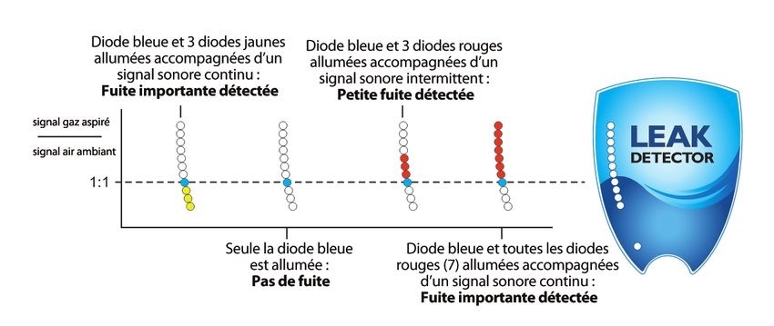
3.0 Powering Up
Depress and hold the power button (Figure 1) until the unit responds                Figure 1: Leak detector schematic.
with the wake-up mode. The leak detector will run through a self-
calibration sequence for approximately 15 seconds. During this time
DO NOT attempt to zero the unit.

4.0 Zeroing the Unit
After the LED lights stop flashing, the unit is ready for use. The instrument
may need to be zeroed periodically between uses, especially if it is moved
from room to room or between areas of differing temperature or humidity.
Do not attempt to zero the unit while the probe is stored in the holder. The
probe MUST be removed from the probe docking station before zeroing the
unit. To re-zero, press the zero set button. The unit will run a self-calibration
sequence for approximately 4 seconds. When all LED lights stop flashing
and the blue LED light is lit, the unit is ready for use.

NOTE: To avoid false readings, do not attempt to use or zero the unit while the self-calibration sequence is in progress.

5.0 Prior to Operation
Verify the operation of the leak detector before each use by sampling gas from a GC split vent or other source of hydrogen or helium. Also,
visually inspect the probe tip, reference gas inlet, and exhaust port for obstructions (Figure 1).

IMPORTANT: Fittings being checked must be clean and dry; liquid leak-detecting agents, dust, and other debris may damage the leak detector if
drawn into the probe.

The leak detector responds to almost any gas you can smell and many gases that you can’t smell. Solvent vapors, split vent exhaust, or even
strong air currents around the probe or reference inlet can cause instability or false positive readings. Be careful not to breathe into the refer-
ence inlet when checking for leaks or to cover/block the inlet with your hand.

                  www.restek.com                                             -4-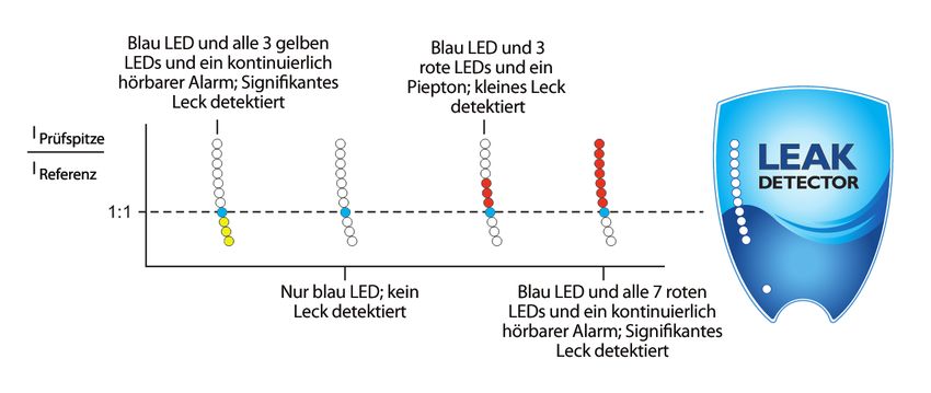
6.0 Detecting Leaks
Slowly move the probe tip around fittings and other potential leak sources. If the leak detector senses a gas other than air, the LED bar graph
will begin to light, with more lights indicating a more significant leak. On the third red, or second yellow LED, an audible tone will begin to
beep. The more LEDs that illuminate, the faster the beep. When the last red or yellow LED illuminates, the beep becomes a steady tone. The red
LED lights indicate a helium or hydrogen leak. The yellow LED lights indicate a nitrogen, argon, or carbon dioxide leak. Remove the probe
from the vicinity of the leak and allow the unit to return to zero. If a large amount of gas has entered the probe, it may take a few seconds
for the instrument to clear itself. Do not attempt to zero the unit while it is clearing out the gas from the probe. This may cause the unit to
malfunction. Place the probe near the leak again to confirm its location. The reference gas inlet (Figure 1) must not be restricted or the unit
will not operate correctly. Similarly, the exhaust port allows the gas being tested to exit the leak detector and must remain unobstructed. The
exhaust port is located in the probe docking station.

CAUTION: This unit is designed to detect trace amounts of hydrogen arising from a small leak in a nonflammable environment, e.g., laboratory
room air, etc. This unit is rated for use in a nonflammable atmosphere where the sample gas may become sufficiently high in concentration to
become explosive.
NOTE: To disable the audible beep during leak detection, depress and hold the zero set button for 2–3 seconds. After you hear a steady tone
for 1 second, release the button; the beep function is disabled. To turn the beep function on again, depress and hold the zero set button. The
beep function is always enabled at power-up.
NOTE: The leak detector will power down after 6 minutes of operation. This feature prevents excess battery discharge if the unit is accidentally
left on.

7.0 Specifications
Power Rating: 3.7 volts DC, 60 mA (AC adaptor supplied)            Warranty: 1-year warranty
Battery Rating: 12 hours normal operation		                        Certifications: CE, Ex, and Japan
Operating Temp. Range: 32–120 °F (0–48 °C)		                       Compliance: WEEE, RoHS, China RoHS2                China RoHS Logo 1

Humidity Range: 0–97%
                                                                                                                 10   China RoHS Logo 2
                                                                                                                      Number Font: Impact

                                                                      -5-                                     www.restek.com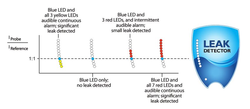
8.0 Maintenance                                                                                                                               Figure 2:                          Figure 3:
Avoid spilling liquids onto the unit or it may malfunction. If a liquid is spilled onto the unit, turn off                                                                       Cap removed,
                                                                                                                                              Cap unscrewed
the power immediately, remove heavy liquids with a dry towel, and let the unit sit until the liquid                                                                              exposing probe tip
                                                                                                                                              and partially
dries. Dust and debris can enter the probe tip of the leak detector and, over time, can clog the small-                                                                          brush for cleaning.
                                                                                                                                              removed.
bore tubing inside the unit. To prevent this, clean the probe tip periodically. To clean the probe tip,
unscrew the cap to expose the brush (Figures 2 and 3). Gently clean the probe using a small brush or
your fingers to remove dust and debris, then replace the cap. Do not use liquids to clean the probe.
Liquids can damage the leak detector if drawn in through the probe.

Information on where to have the unit sent for maintenance or service* is listed at the end of this
document.

9.0 Troubleshooting
 Problem                                                            Possible Cause                                                      Suggested Solution

                                                                    Probe clogged                                                       Clean the probe tip to remove any debris
 Sensitivity decreased
                                                                    Probe line punctured                                                Visually inspect probe line for holes*

 Response decreased                                                 Detector not zeroed                                                 Re-zero detector

                                                                    Detector re-zeroed before unit was purged out                       Allow adequate time for detector to purge, then re-zero
 LED bar graph stays lit during operation
                                                                    Reference gas inlet covered by hand or other object                 Remove obstruction

 Does not power up                                                  Batteries need to be charged                                        Charge unit

*Contact Restek or your Restek representative for return instructions for servicing a damaged unit. Additional charges may apply if the warranty has expired or the unit is damaged due to misuse.

                         www.restek.com                                                            -6-
10.0 Technology
The leak detector measurement is based on thermal conductivity comparisons between the probe air and a reference air. The device employs
a dual thermistor technology that measures the ratio of [probe]:[reference] heat exchange values and displays the results on an LED scale
(Figure 4). Under ideal operating conditions, a ratio of 1:1 indicates identical air samples for both [probe] and [reference], and therefore, no
leak is present.

   Figure 4: Schematic layout of the leak detector technology.

                                                                                          LEFT: Dual analysis is achieved with heater
                                                                                          elements positioned in separate flow chambers.

                                                                                          RIGHT: Probe and reference air streams are
                                                                                          simultaneously monitored for thermal
                                                                                          conductivity. Differences in air composition
                                                                                          are indicated by differences in the heater
                                                                                          element currents.

Because of slight differences in air temperature and/or humidity between the reference inlet (Figure 1) and the probe tip, a small response
indicated by a single red or yellow LED light is generally insufficient to positively identify a gas leak. Small to moderate leaks are reliably
indicated with 3 red or 2 yellow LED lights and an intermittent beep. Larger leaks are indicated with all red or yellow LED lights lit and a
continuous audible alarm.

                                                                      -7-                                       www.restek.com
11.0 Interpretation of Results Minimum Detectable Indicating
Figure 5 illustrates the leak detector’s LED light response range. The Gas Leak Rate (atm cc / sec) LED Light Color
greater the number of red or yellow LED lights lit correlates in general to Helium 1.0 x 10⁻⁵ Red
Hydrogen** 1.0 x 10⁻⁵ Red
the size of the leak. NOTE: The leak detector is not a quantitative device, Nitrogen 1.4 x 10⁻³ Yellow
rather it is designed to detect leaks in gas line connections commonly Argon 1.0 x 10⁻⁴ Yellow
associated with laboratory equipment. Carbon dioxide 1.0 x 10⁻⁴ Yellow
Figure 5: LED light response
chart for the leak detector. A 1:1
ratio of IProbe : IReference indicates
no leak present. Red LED lights
indicate the presence of helium
and/or hydrogen. Yellow LED
lights indicate the presence of
nitrogen, argon, and/or carbon
dioxide.
**CAUTION: This unit is designed to detect trace amounts of hydrogen arising from a small leak in a nonflammable environment, e.g., laboratory room air, etc. This unit is rated for use in a
nonflammable atmosphere where the sample gas may become sufficiently high in concentration to become explosive.
Tip drift
Tip drift is the phenomenon when a false LED light response is registered as the unit is quickly turned or swept in dramatic arc movements. Tip
drift is inherent to all dual thermistor leak detector technology and is based in large part on the asymmetry of the flow cells; shaking or tipping
the unit influences the air flow profiles, which impacts the rates of heat exchange. If the device is functioning normally, the LED light signal will
return to zero in 3–5 seconds after the unit is held still. In extreme cases, the unit may require another “zero” cycle before using. To avoid tip drift,
be sure to hold the unit steady while making measurements.
www.restek.com -8-12.0 Back Label Explanation
1. Product name.
2. Product catalog number.
3. Product serial number.
4. Warning note: This plastic case does not exhibit adequate
surface resistance properties suitable for high electric fields.
DO NOT CHARGE THIS DEVICE IN A HAZARDOUS AREA.
5. Definition of symbols—see table at right.
6. This unit conforms to EU/EMC Directive 2004/108/EC,
Standards to which Conformity is declared include
EN61326-1:2006 w/A3 Class A.
Definition of back label symbols.
7. Unit is WEEE compliant.
_ _ _ DC Voltage.
8. Unit is RoHS and China RoHS2 compliant. Ex nA EN60079-0: 2012; Electrical apparatus for explosive gas atmospheres—Part 0: General Requirements
EN60079-15: 2010; Electrical apparatus for explosive gas atmospheres—Part 15:
9. This complies with part 15 of the FCC Rules. Operation is Electrical Apparatus With Type of Protection “n.”
subject to the following two conditions: (1) this device may not IIC Group II applies to areas above ground environments. Gas Group IIC relates to hydrogen and
related gas types.
cause harmful interference, and (2) this device must accept any T6 While testing this unit neither internal nor external elements exceed 85 °C.
interference received, including interference that may cause X Additional information.
undesired operation. Operating range. 32 °F ≤ Tamb ≤ 120 °F
0 °C ≤ Tamb ≤ 48 °C
10. This Class A digital apparatus complies with Canadian ICES-003. This unit is designed to detect trace amounts of hydrogen arising from a small leak in a
nonflammable environment, e.g., laboratory room air, etc.
11. Units must be sent back to Restek Corporation for service. This unit is rated for use in a nonflammable atmosphere where the sample gas may become
12. Manufacturer company name, address, and contact information. sufficiently high in concentration to become explosive.
13.0517 Certificate Reference.
13. Electrical parameters. EU Explosive Atmosphere symbol.
14. ATEX coding: for definition of symbols see table to the right. 11 Equipment Group (non-mining).
3 Normal protection.
15. Passed California Energy Commission (CEC) Battery Charging G Gas.
System (BCS) testing. Testing according to California Code of Regulations, Title 20: Division 2, Chapter 4, Article 4,
Sections 1601-1608: Appliance Efficiency Regulations (2015) Test Specification: 10 CFR Section
For the most up-to-date information, see our website 430.23(aa) (Appendix Y to Subpart B of Part 430) June 20, 2016.
www.restek.com/leakdetector
-9- www.restek.com13.0 Case Specifications 14.0 Service
The Restek leak detector carries a one-year limited warranty from
time of purchase. Please have the leak detector serial number
available when calling Restek with any concerns you may have.
Additional charges may apply if the warranty is expired or the dam-
age is due to misuse.
Expected battery lifetime is two years from time of purchase.
Customers will need to return the unit to Restek for battery replace-
ment. At that time, preventative maintenance services can also be
performed on the unit. A fee will be charged for servicing the unit.
For questions, problems, or repair services:
Within the U.S.:
Call Restek Customer Service at 1-800-356-1688 or
1-814-353-1300, ext. 3.
Outside the U.S.:
Contact your local Restek representative.
www.restek.com - 10 -Restek Elektronischer Leak Detektor (ArtNr. 22655)
Bedienungsanleitung
I nhaltsverzeic hnis............................................ Seite
1.0 Einleitung............................................................................. 12
2.0 Akku aufladen. . .................................................................... 12
3.0 Einschalten........................................................................... 13
4.0 Nullabstimmung . . ................................................................ 13
5.0 Vor Inbetriebnahme........................................................... 13
6.0 Auffindung von Lecks........................................................ 14
7.0 Spezifikationen . . .................................................................. 14
8.0 Wartung................................................................................ 15
9.0 Troubleshooting. . ................................................................ 15
10.0 Technik . . ............................................................................... 16
11.0 Interpretation der Messwerte. . ......................................... 17
12.0 Erklärung des Labels auf der Rückseite.......................... 18
13.0 Spezifikationen des Gehäuses.......................................... 19
14.0 Service. . ................................................................................. 19
Konformitätserklärung....................................................... 29
- 11 - www.restek.comBedienungsanleitung
1.0 Einleitung
Restek’s tragbarer Leak Detektor wurde speziell für die Benutzung in Gaschromatographie (GC) Systemen entwickelt. Dieser detektiert
hochempfindlich Gase, die sich in ihrer Wärmeleitfähigkeit vom Referenzgas – im Regelfall Luft – unterscheiden. Der Referenzgas Inlet
(Abbildung 1) saugt Luft aus der Umgebung an, die zum Vergleich mit dem Gas in der Prüfspitze benutzt wird. Das Ausmaß eines Lecks wird
sowohl durch eine LED Lichtanzeige, wie auch durch ein hörbares Signal angedeutet.
Am Besten nutzen Sie den Leckdetektor täglich, um alle kritischen Verbindungen in Ihrem Gaschromatografen auf Dichtigkeit zu prüfen.
Wenn das Gerät anders als in dieser Bedienungsanleitung beschrieben benutzt wird, verfallen die CE und EX Zertifikate.
Restek’s Leak Detektor wird von Restek hergestellt. Dadurch wird die Qualität gewährleistet, die Sie mit dem Namen Restek identifizieren.
Sollten Sie Hilfe mit Ihrem Leak Detektor benötigen, wenden Sie sich bitte an den Restek Customer Service.
2.0 Akku aufladen
Der Leak Detektor sollte vor Gebrauch vollständig aufgeladen werden. Dazu nur den mitgelieferten AC Adapter benutzen. Um den Akku aufzuladen
installieren Sie zuerst den richtigen Stecker für Ihr Land. Stecken Sie den Adapter in die Steckdose und dann das andere Ende in die Öffnung unten
am Leckdetektor. Das grüne LED leuchtet auf und zeigt an, dass der Akku aufgeladen wird. Wenn der Akku voll aufgeladen ist, geht das grüne LED
aus. Wenn der Akku fast leer ist, blinkt ein blaues LED. Es befindet sich zwischen dem roten und gelben LED. Das blaue LED kann auch blinken,
wenn das Gerät eingeschaltet wird. Wenn der Akku vollständig leer ist, zeigt das LED nichts an.
Vorsicht: Der Leckdetektor enthält eine Li-Ionen Batterie. Diese sollte nie über einen längeren Zeitraum unbenutzt bleiben, da sie
sich soweit entladen kann, dass ein Wiederaufladen durch eine Sicherung verhindert wird. Wir empfehlen deshalb, die
Batterie mindestens einmal alle drei Monate komplett zu laden. Wenn Ihr Leck-Detektor häufiger als empfohlen zur
Routinewartung Ihres Geräteparks eingesetzt wird, kann ein häufigeres Laden des Akkus notwendig werden.
Vorsicht: Laden Sie den Detektor nicht in ungeeigneten Bereichen.
Anmerkung: Die Akkus im Gerät können nur vom Hersteller ersetzt werden. Es gibt keine Teile in diesem Gerät die eine Wartung
benötigen. Wenn Sie das Gehäuse öffnen oder die internen Teile entfernen, verfällt die Garantie des Herstellers.
Anmerkung: Das Aufladen eines Akkus mit niedrigem Ladestatus kann 3-5 Stunden dauern.
Anmerkung: Wenn Sie das Gerät trotz eines niedrigen Ladestatus des Akkus verwenden müssen, können Sie es für 15 Minuten an eine
Stromquelle anschließen und dann, nach Trennung von der Stromquelle, für ca. 30 Minuten nutzen. Bitte laden Sie danach
den Akku wieder vollständig auf.
www.restek.com - 12 -3.0 Einschalten
Abbildung 1: Leak Detektor Diagramm.
Drücken Sie die Power-Taste (Abbildung 1) bis das Gerät mit dem
Aufwachmodus startet. Der Leak Detektor führt dann eine
Selbstkalibrierungssequenz durch die 15 Sekunden dauert. Während
dieses Ablaufs auf keinen Fall versuchen das Gerät auf Null einzustellen. Aufbewahrung
der Prüfspitze/
Gasoutlet
Prüfspitze
4.0 Nulleinstellung Referenzgas
Wenn die LED Lichter aufhören zu blinken, ist das Gerät zur Benutzung LED Leak Inlet
Indikator Lichter (Freihalten)
bereit. Das Gerät muss von Zeit zu Zeit wieder auf Null eingestellt werden.
LED Akku Auflade
Besonders dann, wenn es in einem anderen Raum benutzt wird, oder Indikator Licht
wenn sich die Temperatur oder Luftfeuchtigkeit ändert. Niemals eine
Prüfspitze
Nulleinstellung versuchen, wenn sich die Prüfspitze in der Halterung
Power Taste/
befindet. Die Prüfspitze MUSS vor der Nulleinstellung aus der Halterung Nulleinstellungstaste
genommen werden. Zur Nulleinstellung die „Zero“ Taste drücken. Das Ansicht Ansicht
Gerät führt eine Selbstkalibrierungssequenz durch, die etwa 4 Sekunden vorne hinten
dauert. Wenn alle LED Lichter aufhören zu blinken und das blaue LED
Licht aufleuchtet, ist das Gerät zur Benutzung bereit.
Anmerkung: Um falsche Messwerte zu vermeiden, sollten Sie nicht versuchen das Gerät während der Selbstkalibrierungssequenz zu benutzen.
5.0 Vor der Inbetriebnahme
Überprüfen Sie den Betrieb des Leak Detektors vor jedem Gebrauch indem Sie ihn mit Gas vom GC Split Vent oder anderen Quellen von
Wasserstoff oder Helium testen. Sie sollten auch die Prüfspitze, den Referenzgasinlet und das Gasoutlet auf Störungen untersuchen (Abbildung 1).
WICHTIG: Zu überprüfende Dichtungen müssen sauber und trocken sein; flüssige Reagenzien zum Detektieren von Lecks, Staub und
andere Rückstände können den Leak Detektor beschädigen, wenn sie in die Prüfspitze gezogen werden.
Der Leak Detektor spricht auf fast alle Gase—riechbar und nicht-riechbar—an. Lösungsmitteldämpfe, Split Vent Abgase oder sogar starke
Luftströmungen um die Prüfspitze oder den Referenzinlet können zu Instabilität oder falschen Messwerten führen. Beachten Sie, dass Sie
während der Messung nicht in den Referenzinlet atmen oder mit der Hand den Inlet blockieren.
- 13 - www.restek.com6.0 Auffindung von Lecks
Die Prüfspitze langsam an den Dichtungen oder anderen potentiellen Leckquellen vorbeiführen. Wenn der Leak Detektor auf ein Gas (dass
sich von Luft unterscheidet) anspricht, fangen die LED Lichter an zu leuchten und je größer das Leck ist, umso mehr Lichter leuchten auf.
Am dritten roten oder zweiten gelben LED ertönt Sie ein Piepton. Je mehr LED Lichter aufleuchten, desto schneller ist die Tonfolge. Wenn
alle roten oder gelben LED aufleuchten, wechselt der Piepton zum Dauerton. Die roten LED Lichter bedeuten entweder Helium- oder
Wasserstoff-Leaks. Die gelben LED Lichter zeigen Stickstoff-, Argon- oder Kohlendioxid-Leaks an. Entfernen Sie die Prüfspitze von dem
Leak und lassen Sie das Gerät auf Null zurückkommen. Wenn viel Gas in der Prüfspitze ist, kann dies ein paar Sekunden dauern. Bitte ver-
suchen Sie nicht das Gerät während dieser Phase auf Null einzustellen. Das kann zu Störungen führen. Halten Sie die Prüfspitze nun noch-
mals an das Leck um die genaue Position zu bestätigen. Der Referenzgasinlet (Abbildung 1) darf nicht eingeschränkt sein, sonst funktioniert
das Gerät nicht einwandfrei. Genauso muss der Gasoutlet offen und nicht behindert sein. Der Gasoutlet befindet sich in der Halterung der
Prüfspitze.
VORSICHT: Dieses Gerät wurde entwickelt um Spuren von-Brenn- und Trägergasen, die aus kleinen Lecks austreten, in einer nicht-bren-
nbaren Umgebung nachzuweisen. Dieses Gerät sollte nur in einer nicht entzündlichen Atmosphäre eingesetzt werden, da es nur bedingt
explosionsgeschützt ist.
Um den Piepton auszuschalten, drücken Sie die „Zero“ Taste für 2-3 Sekunden. Lassen Sie die Taste los, wenn Sie einen Dauerton hören.
Der Piepton ist jetzt ausgeschaltet. Um ihn wieder einzuschalten wiederholen Sie den obigen Vorgang. Die Funktion wird beim Einschalten
immer aktiviert.
Anmerkung: Der Leckdetektor schaltet sich nach 6 Minuten Benutzung aus. Dadurch wird versehentliches Entladen des Akkus verhindert.
7.0 Spezifikationen
Leistung Ladegerät: 3.7 Volt DC, 60 mA (AC Adapter wird mitgeliefert) Garantie: 1 Jahr Garantie.
Akku Werte: 12 Stunden Normalbetrieb Zertifikate: CE, Ex und Japan
Betriebstemperaturbereich: 0–48 °C Befolgungen: WEEE, RoHS, China RoHS2 China RoHS Logo 1
Luftfeuchtigkeitsbereich: 0–97%
10 China RoHS Logo 2
Number Font: Impact
www.restek.com - 14 -8.0 Wartung Abbildung 2: Abbildung 3:
Keine Flüssigkeiten auf das Gerät verschütten; es könnte dadurch zu Störungen kommen. Falls eine Deckel Deckel entfernt,
Flüssigkeit auf das Gerät verschüttet wird, sollten Sie dieses sofort ausschalten. Die Flüssigkeit mit einem aufgeschraubt man sieht die kleine
trockenen Handtuch entfernen und das Gerät trocknen lassen. Staub und andere Rückstände und Bürste zum Reinigen.
können in die Prüfspitze eindringen und sich dort ansammeln. Dadurch kann die kleine Leitung in dem teilweise
Gerät verstopft werden. Um das zu vermeiden sollte die Prüfspitze von Zeit zu Zeit gereinigt werden. Um
entfernt.
die Prüfspitze zu reinigen, schrauben Sie den Deckel ab bis Sie die Bürste sehen (Abbildungen 2 und 3).
Die Prüfspitze vorsichtig mit der Bürste oder den Fingern reinigen, Staub und Rückstände entfernen und
danach den Deckel wieder aufschrauben. Keine Flüssigkeiten zum Reinigen benutzen. Flüssigkeiten kön-
nen den Leak Detektor beschädigen, wenn Sie durch die Prüfspitze in das Gerät gesaugt werden.
Information über Wartungs- oder Reperaturstellen* finden Sie am Ende dieser Anleitung.
9.0 Troubleshooting
Problem Mögliche Ursache Vorgeschlagene Lösung
Prüfspitze verstopft Die Prüfspitze reinigen um Rückstände zu entfernen
Verminderte Empfindlichkeit.
Prüfspitzenleitung hat ein Loch Die Leitung auf Löcher inspizieren*
Verminderte Response. Detektor nicht auf Null eingestellt Detektor wieder auf Null einstellen
Detektor auf Null eingestellt bevor das Gerät vollständig ausgespüllt war Genug Zeit zum Ausspülen lassen, dann wieder auf Null einstellen
LED Lichter bleiben während der Benutzung ständig an.
Referenzgasinlet mit der Hand oder anderem Gegenstand blockiert Behinderung entfernen
Gerät schaltet sich nicht ein. Akku muss aufgeladen werden Das Gerät aufladen
*Setzen Sie sich mit Restek oder Ihrem Restek Händler in Verbindung, wenn Sie Anleitungen brauchen um ein beschädigtes Gerät zur Reperatur einzuschicken. Es können zusätzliche Gebühren
auftretten wenn die Garantie abgelaufen ist oder das Gerät durch Mißhandlung beschädigt wurde.
- 15 - www.restek.com10.0 Technik
Die Leak Detektor Messtechnik beruht auf dem Vergleich der Wärmeleitfähigkeit zwischen dem gemessenen Gas und der Luft. Das Gerät
benutzt eine Dual Thermistor Technik, die das Verhältnis der Wärmewechselwerte Probengas : Luft misst und das Ergebnis auf einer LED
Anzeige überträgt (Abbildung 4). Unter idealen Bedingungen liegt ein Verhältnis von 1:1 vor, da sich das gleiche Gas in der Prüfspitze wie
auch in der Referenzzelle befindet.
Abbildung 4: Diagramm der Leak Detektor Technik.
LINKS: Dualanalyse wird dadurch erreicht
dass sich die Wärmeelemente in getrennten
Flussräumen angebracht sind
RECHTS: Prüfspitze und Referenzgasfluss
werden simultan auf Wärmeleitfähigkeit
überwacht. Unterschiede in der
Zusammensetzung der Gase wird
durch Unterschiede im Stromfluss der
Wärmeelemente angezeigt.
Da es kleine Unterschiede in der Lufttemperatur und/oder Luftfeuchtigkeit zwischen dem Referenzinlet (Abbildung 1) und der Prüfspitze
geben kann, gilt eine kleine Response (nur ein einziges rotes oder gelbes LED Licht) im Allgemeinen nicht als positives Zeichen für ein Leck.
Kleine bis mittelmäßige Lecks werden zuverlässig durch drei rote oder zwei gelbe LED Lichter angezeigt und einem Piepton. Bei großen
Lecks leuchten alle roten LED Lichter-oder alle gelben LED Lichter auf und ein kontinuierlicher Alarm ist hörbar.
www.restek.com - 16 -11.0 Interpretation der Messwerte Minimale nachweisbare Angezeigte
Abbildung 5 veranschaulicht den Bereich der LED Lichter des Leak Gas Leckrate (atm cc / sec) LED Licht Farbe
Detektors. Je mehr rote oder gelbe LED Lichter aufleuchten, desto größer Helium 1.0 x 10⁻⁵ Rot
Wasserstoff** 1.0 x 10⁻⁵ Rot
ist das Leck. Anmerkung: Der Leak Detektor ist keine quantitative Stickstoff 1.4 x 10⁻³ Gelb
Vorrichtung. Er wurde entwickelt um Lecks in solchen Gasleitungen zu Argon 1.0 x 10⁻⁴ Gelb
finden, wie sie gewöhnlich in analytischen Labors vorkommen. Kohlendioxyd 1.0 x 10⁻⁴ Gelb
Abbildung 5: LED Licht Response
Tabelle für den Leak Detektor. Ein
Verhältnis von 1:1 zwischen IPrüfspitze
: IReferenz zeigt an, dass kein Leck
existiert. Rote LED Lichter zeigen
an, dass Gase mit einer höheren
Wäremeleitfähigkeit vorhanden sind:
z.B. Helium oder Wasserstoff. Gelbe
LED Lichter zeigen an, dass Gase mit
einer niedrigeren Wärmeleitfähigkeit
vorhanden sind: z.B. Stickstoff,
Argon oder Kohlendioxid.
**VORSICHT: Dieses Gerät wurde entwickelt um Spuren von Brenn- & Trägergasen, z.B. Wasserstoff, die aus kleinen Lecks austreten, in einer nicht-brennbaren Umgebung nachzuweisen. Dieses
Gerät sollte nur in einer nicht entzündlichen Atmosphäre eingesetzt werden, da es nur bedingt explosionsgeschützt ist.
Abweichung der Prüfspitze
Eine Abweichung der Prüfspitze liegt dann vor, wenn eine falsche LED Licht Response registriert wird, da das Gerät schnell bewegt wurde. Eine
Abweichung der Prüfspitze kommt bei allen Dual Thermistor Leak Detektoren vor. Sie basiert auf der Asymmetrie der Flusszellen; schütteln oder
neigen des Geräts beeinflusst die Luftströmungsprofile, was sich wiederum auf die Wärmewechselraten auswirkt. Wenn das Gerät normal funk-
tioniert, kehrt das LED Lichtsignal in 3-5 Sekunden wieder auf Null zurück sobald das Gerät wieder still steht. In extremen Fällen kann es sein, dass
Sie das Gerät vor dem nächsten Gebrauch wieder auf Null einstellen müssen. Um Fehlmessungen zu vermeiden, sollten Sie das Gerät während der
Messungen ruhig halten.
- 17 - www.restek.com12.0 Erklärung des Aufklebers auf der Rückseite
1. Name des Produktes.
2. Artikelnummer des Produktes.
3. Seriennummer des Produktes.
4. Warnung: Dieses Plastikgehäuse hat keinen ausreichenden
Oberflächenwiderstand für starke elektrische Felder. DIESES
GERÄT NICHT IN GEFÄHRLICHEM UMFELD AUFLADEN.
5. Definition der Symbole—siehe Tabelle rechts.
6. Dieses Gerät entspricht EU/EMC Direktive 2004/108/EC,
andere Standards, denen es entspricht, sind u.a.
EN61326-1:2006 w/A3 Class A.
7. Gerät erfüllt WEEE.
8. Gerät erfüllt RoHS, China RoHS2. Definition der Symbole auf der Rückseite
_ _ _ DC Voltage.
9. Dadurch wird Teil 15 der FCC Regeln erfüllt. Betrieb ist abhängig Ex nA EN60079-0: 2012; Elektrischer Apparat für Atmosphären mit explosivem Gas—Teil 0: Allgemeine
von den folgenden zwei Bedingungen: (1) Diese Gerät darf zu Anforderungen
keinen schädlichen Störungen führen, und (2) dieses Gerät muss EN60079-15: 2012; Elektrischer Apparat für Atmosphären mit explosivem Gas—Teil 15:
Elektrischer Apparat mit Schutztyp “n.”
empfangene Störungen akzeptieren, was auch Störungen beinhaltet IIC Gruppe II ist für Umgebungen über Grund. Gas Gruppe IIC ist für Wasserstoff und
die zu unerwünschtem Betrieb führen können. verwandte Gasarten.
T6 Während dieses Gerät geprüft wurde hat die Temperatur der externen und internen
10. Dieser digitale Apparat, der Klasse A, erfüllt Kanadische ICES-003. Teile 85 °C nicht überschritten.
11. Geräte müssen zum Service an Restek Corporation X Zusätzliche Informationen.
zurückgeschickt werden Betriebsbereich. 0 °C ≤ Tamb ≤ 48 °C
Dieses Gerät wurde entwickelt um Spuren von Wasserstoff von einem kleinen Leck in einer
12. Hersteller Name, Adresse und Kontaktinformation. nicht-brennbaren Umgebung nachzuweisen, z. B., in Laborluft, usw. Dieses Gerät ist geeignet
für eine nicht-brennbare Atmosphäre in der das Probengas zu einer Konzentration ansteigen kann,
13. Elektrische Parameter wo es explosiv werden kann.
14. ATEX Coding zur Definition der Symbole in der Tabelle rechts 13.0517 Zertifikatsreferenz.
15. Hat den California Energy Commission (CEC) Batterielade- EU Explosions Atmosphärensymbol.
Testzyklus (BCS) bestanden. 11 Gerätegruppe.
3 Normaler Schutz.
Aktuelle Information finden Sie auf unserer Webseite G Gas.
www.restek.com/leakdetector Testzyklus gemäß der California Code of Regulations, Titel 20, Division 2, Abschnitt 4, Artikel 4,
Satz 1601-1608: Appliance Efficiency Regulations (2015) Test-Spezifikation: 10 CFR, Satz 430.23
(aa) (Anhang Y zu Untergruppe B des Teils 430), 20. Juni 2016.
www.restek.com - 18 -13.0 Spezifikationen des Gehäuses 14.0 Service
Der Restek Leak Detektor hat eine beschränkte Garantie von
1 Jahr ab Verkaufsdatum. Haben Sie bitte die Leak Detektor
Einspritzgeformtes Seriennummer zur Hand, wenn Sie Restek mit Fragen anrufen. Es
Cycoloy C6200 kann eine zusätzliche Gebühr erhoben werden, wenn die Garantie
Weis 8T7D009 mit
MT-11030 Oberfläche abgelaufen ist oder das Gerät falsch benutzt wurde.
Einspritzgeformter
Silikongummi Schwarz
Die Lebenserwartung des Akkus beträgt 2 Jahre ab Verkaufsdatum.
gedruckte Graphiken Weise Kunden müssen zum Austausch des Akkus das Gerät an Restek
Polyurethanbeschichtung
zurückschicken. Gleichzeitig kann ein Wartungsdienst
geleistet werden. Für diesen Wartungsservice wird eine Gebühr
Einspritzgeformtes
Versaflex 1040X-1 erhoben.
Schwarzes Pantone 426C
mit MT-1055 Oberfläche
Für Fragen, Probleme, Reparaturservice:
In Deutschland:
Restek GmbH • Schaberweg 23 • 61348 Bad Homburg
Tel. 06172 2797 0 • Fax 06172 2797 77 • info@restekgmbh.de • www.restekgmbh.de
Innerhalb der U.S.:
Rufen Sie Restek Customer Service unter 001-814-353-1300, ext. 3 an.
Andere Länder:
Kontaktieren Sie Ihren Restek Händler.
- 19 - www.restek.comDétecteur de fuites de gaz (Réf. 22655)
Manuel d’utilisation
Contenu du manuel....................................................................... Page
1.0 Introduction.................................................................................................... .21
2.0 Recharge des batteries............................................................................... .21
3.0 Mise en marche.............................................................................................. .22
4.0 Mise à zéro....................................................................................................... .22
5.0 Avant l’utilisation.......................................................................................... .22
6.0 Détection des fuites..................................................................................... .23
7.0 Caractéristiques............................................................................................. .23
8.0 Entretien........................................................................................................... .24
9.0 Résolution des problèmes......................................................................... .24
10.0 Principe de fonctionnement .................................................................... .25
11.0 Interprétation des résultats....................................................................... .26
12.0 Signification des informations au dos de l’appareil......................... .27
13.0 Matériaux composant la coque de l’appareil........................... .28
14.0 Garantie/Dépannage................................................................................... .28
Certificat de conformité.............................................................................. .29
www.restek.com - 20 -1.0 Introduction
Ce détecteur de fuites de gaz portatif est spécialement conçu pour les besoins de la chromatographie en phase gazeuse (GC). Il peut détecter les
micro-fuites de tout gaz dont la conductivité thermique est différente de celle de l’air. Un orifice situé à l’arrière de l’appareil (Figure 1) permet
l’introduction d’air ambiant dont la conductivité est comparée avec celle de l’air aspiré par la sonde de prélèvement. Une éventuelle présence de
gaz (dans l’air aspiré), est indiquée par l’allumage d’une ou plusieurs diodes et par un signal sonore.
Il est recommandé d’utiliser quotidiennement ce détecteur pour vérifier l’absence de fuites au niveau des raccords, écrous, lignes de gaz, joints,
manomètres, …
Une utilisation de l’appareil non conforme à celle décrite dans le présent manuel annulerait les certifications CE et Ex declaration.
Ce manuel est destiné à répondre à toutes vos questions concernant le détecteur de fuites de gaz Restek. Pour tout renseignement
complémentaire contacter Restek France au 01 60 78 32 10 ou votre distributeur habituel.
2.0 Recharge des batteries
Les batteries doivent être rechargées avant l’utilisation du détecteur de fuites. Seul le transformateur fourni avec l’appareil peut être utilisé pour
la recharge des batteries. L’appareil pouvant être utilisé dans différents pays, l’adaptateur secteur approprié doit être au préalable monté sur le
transformateur. Connecter ensuite le transformateur à une prise de courant puis l’autre extrémité à la base du détecteur de fuites. Le témoin de charge
vert s’allume. Ce témoin s’éteint lorsque les batteries sont totalement rechargées. Une durée de 3 à 5 heures est nécessaire pour recharger des batteries
déchargées. Le clignotement de la diode bleue située entre les diodes rouges et jaunes, indique un niveau de charge faible.
IMPORTANT : Cet appareil est équipé de batteries de type lithium ion. Elles doivent subir un cycle de recharge complète au moins une fois
tous les 3 ou 4 mois. A défaut, elles risquent d’être irrémédiablement endommagées. L’appareil sera alors inutilisable.
Si l’appareil est utilisé quotidiennement, les batteries devront être rechargées plus fréquemment.
ATTENTION : Ne pas recharger l’appareil dans un lieu présentant des risques.
A noter : L’ éventuel remplacement des batteries ne peut être réalisé que par Restek. Cet appareil ne nécessite aucune intervention de la
part de l’utilisateur. L’ ouverture de l’appareil ou toute manipulation des éléments internes annule la garantie.
A noter : Pour utiliser l’appareil rapidement alors que les batteries sont déchargées, une charge rapide de 15 minutes
permet une utilisation d’environ 30 minutes (après déconnexion du secteur). Il convient ensuite de recharger complètement
les batteries.
- 21 - www.restek.com3.0 Mise en marche
Figure 1 : Schéma du détecteur de fuites.
Presser et maintenir le bouton Marche/Arrêt/Mise à zéro (Figure 1)
jusqu’à la mise en marche de l’appareil. Celui-ci effectue alors une
autocalibration qui dure environ 15 secondes. NE PAS tenter de Logement de la
mettre l’appareil à zéro durant cette étape. L’appareil peut être utilisé sonde/ orifice
d’échappement
lorsque toutes les diodes cessent de clignoter. Tube souple du gaz aspiré
Orifice
4.0 Mise à zéro de l’appareil Diodes rouges d’admission
et jaunes d’air (ne pas
Une remise à zéro peut être nécessaire entre deux utilisations notamment boucher)
si le détecteur est déplacé d’une pièce à une autre ou entre des endroits Indicateur de
à températures et taux d’humidité différents. NE PAS tenter une mise à charge
Sonde
zéro lorsque la sonde est rangée dans son logement. Pour la remise à zéro, Marche/Arrêt/
appuyer sur le bouton Marche/Arrêt/Mise à zéro. L’appareil effectue une Mise à zéro
autocalibration durant 4 secondes. Le détecteur peut être utilisé lorsque Face Face
toutes les diodes cessent de clignoter et que la diode bleue est allumée. avant arrière
A noter : L’appareil ne doit pas être utilisé ou remis à zéro durant son auto-calibration.
5.0 Avant l’utilisation
Vérifier si possible le bon fonctionnement du détecteur de fuites avant chaque utilisation en approchant la sonde d’une source d’hydrogène
ou d’hélium. S’assurer également que l’extrémité de la sonde, les orifices d’entrée d’air et d’échappement du gaz aspiré ne sont pas obstrués
(Figure 1).
IMPORTANT : Les raccords, tubes, soudures, ... sur lesquels les fuites sont recherchées, doivent être propres et secs. Des liquides, poussières ou
autres débris aspirés par la sonde peuvent endommager le détecteur de fuites.
Le détecteur de fuites détecte presque tous les gaz odorants et la plupart des gaz inodores. Des vapeurs de solvants ou même de forts courants d’air
circulant près de la sonde ou de l’orifice d’admission d’air, peuvent provoquer une certaine instabilité de l’appareil et une mauvaise interprétation
du signal obtenu. Ne pas souffler dans l’orifice d’amission d’air et prendre soin de ne pas le boucher en le maintenant.
www.restek.com - 22 -6.0 Détection des fuites
Déplacer lentement l’extrémité de la sonde autour ou le long des surfaces susceptibles de fuir. Si l’appareil détecte un gaz différent de l’air,
une ou plusieurs diodes s’allument. Un signal sonore intermittent est émis lorsque trois diodes rouges ou deux diodes jaunes s’allument.
La fréquence des « bips » s’accélère si davantage de diodes s’allument. Le signal sonore devient continu lorsque toutes les diodes rouges
ou jaunes s’allument. Les diodes rouges signalent des fuites d’hélium ou d’hydrogène. Les diodes jaunes indiquent la présence de fuites
d’azote, d’argon ou de dioxyde de carbone. Eloigner la sonde de la source de la fuite pour permettre au détecteur de revenir à l’équilibre
(zéro). Si une grande quantité de gaz est aspirée par la sonde, quelques secondes sont nécessaires pour qu’elle soit éliminée et pour la remise
à zéro automatique. Ne pas essayer de remettre à zéro l’appareil durant ce laps de temps au risque de provoquer un dysfonctionnement
du détecteur. Approcher de nouveau la sonde près de la fuite pour en déterminer l’emplacement exact. Pour un bon fonctionnement de
l’appareil, l’orifice d’admission d’air (Figure 1) ne doit pas être obstrué. Il en est de même pour l’orifice d’échappement du gaz aspiré, situé
dans le logement de la sonde.
Attention : Cet appareil est conçu pour détecter des traces d’hydrogène provenant d’une faible fuite en milieu ininfammable comme par
exemple l’air ambiant d’un laboratoire. Ce détecteur est calibré pour une utilisation en milieu ininflammable dans lequel la concentration du
gaz dont la fuite est détectée peut provoquer une explosion.
A noter : Pour désactiver le signal sonore indiquant la détection de gaz, presser le bouton de Mise en marche/Arrêt/Mise à zéro durant 2 à 3
secondes. Un « bip » constant d’une seconde indique la désactivation du signal sonore. Relâcher le bouton. Procéder de la même façon pour
réactiver le signal sonore. Le signal sonore est automatiquement réactivé à chaque remise en marche de l’appareil.
A noter : L’appareil s’arrêtera automatiquement après 6 minutes, ceci afin d’éviter que les batteries ne se déchargent si le détecteur est laissé en
marche par inadvertance.
7.0 Caractéristiques
Alimentation : 3.7 volts CC, 60 mA (chargeur de batteries fourni) Garantie : 1 an
Autonomie : 12 heures en utilisation normale Certifications : CE, Ex
Température d’utilisation : 0° à 48°C (32-120°F) Conformité : WEEE, RoHS, China RoHS2 China RoHS Logo 1
Taux d’humidité acceptable à l’utilisation : 0 à 97%
10 China RoHS Logo 2
Number Font: Impact
- 23 - www.restek.com8.0 Entretien Figure 2 : Figure 3 :
Eviter de renverser des liquides sur le détecteur. Si cela se produit, arrêter immédiatement l’appareil Le démontage de
Démontage de
puis essuyer-le avec du papier ou un chiffon absorbant. Le laisser ensuite sécher complètement l’embout permet
l’embout de la
avant de le réutiliser. Des poussières ou des débris peuvent être aspirés dans la sonde et à la longue le nettoyage de la
sonde.
boucher la tubulure étroite à l’intérieur de l’appareil. Pour éviter ce problème, nettoyer régulièrement brosse-filtre.
l’embout de la sonde. Pour cela dévisser cet embout pour accéder à la brosse-filtre de la sonde
(Figures 2 et 3). Eliminer précautionneusement les poussières ou débris puis revisser l’embout.
N’utiliser aucun liquide pour cette opération au risque d’endommager le détecteur.
Voir le paragraphe 14.0 concernant le remplacement des batteries ou toute intervention nécessaire
à l’intérieur du détecteur.
9.0 Résolution des problèmes
Problème Causes possibles Actions recommandées
Sonde bouchée Nettoyer la brosse-filtre de la sonde
Perte de sensibilité
Tube souple percé Inspecter le tube souple
Perte de réponse Détecteur non remis à zéro Remettre l’appareil à zéro
Détecteur remis à zéro avant l’évacuation du gaz aspiré par l’évent Laisser le détecteur évacuer l’air aspiré et revenir à l’équilibre
Les diodes restent allumées L’orifice d’admission d’air est bouché Prendre soin de ne pas obstruer l’orifice d’admission en le
maintenant ou retirer l’objet qui bouche cet orifice
Impossible de mettre l’appareil en marche Les batteries sont déchargées Recharger les batteries
www.restek.com - 24 -10.0 Principe de fonctionnement
Le détecteur de fuites fonctionne sur le principe de la comparaison de la conductivité thermique du gaz aspiré par la sonde avec celle de l’air
ambiant. L’appareil contient un système à double thermistances qui mesure le rapport d’équilibre thermique entre le gaz aspiré par la sonde
et celui de l’air ambiant. L’allumage d’une ou plusieurs diodes exprime l’ampleur de ce rapport (Figure 4). En absence de fuites de gaz, le
rapport est de 1:1 puisque l’air aspiré et l’air admis pour comparaison sont identiques et présentent la même conductivité thermique.
Figure 4 : Schéma de fonctionnement.
A gauche : Le système comprend deux thermistances
placées dans deux chambres distinctes, l’une pour l’air
ambiant, l’autre pour le gaz aspiré par la sonde.
A droite : Le gaz aspiré et l’air ambiant de référence entrent
dans leur chambre respective et leur conductivité thermique
est contrôlée. La différence de conductivité est détectée par
l’écart entre les courants traversant les thermistances.
De faibles écarts de température et/ou de taux d’humidité entre l’orifice d’admission d’air de référence et l’extrémité de la sonde (Figure 1),
peuvent expliquer une faible réponse du détecteur et l’allumage d’une diode rouge ou jaune sans que cela signifie la présence d’une fuite.
L’allumage de 3 diodes rouges ou 2 diodes jaunes et un signal sonore intermittent révèlent une fuite faible à modérée. L’allumage de toutes
les diodes rouges ou jaunes suivi d’un signal sonore indique une fuite importante.
- 25 - www.restek.com11.0 Interprétation des résultats Débit de fuite minimum Signalisation
La Figure 5 explique la signification de l’allumage des diodes de différentes couleurs. Gaz détectable (cc/sec.) de couleur
De façon générale, plus il y a de diodes allumées, plus la fuite est importante. Hélium 1.0 x 10⁻⁵ rouge
Hydrogène** 1.0 x 10⁻⁵ rouge
IMPORTANT : Cet appareil ne permet pas des mesures quantitatives mais Azote 1.4 x 10⁻³ jaune
uniquement de détecter des fuites sur des lignes de gaz, des points de raccordement, Argon 1.0 x 10⁻⁴ jaune
des réservoirs, ... Dioxyde de carbone 1.0 x 10⁻⁴ jaune
Figure 5 : Un rapport d’équilibre
thermique entre le gaz aspiré par
la sonde et celui de l’air ambiant
de 1:1 indique une absence de
fuite. L’allumage de diodes rouges
signale la présence d’au moins
un des gaz suivants : hélium ou
hydrogène. L’allumage de diodes
jaunes informe de la présence d’au
moins un des gaz suivants : azote,
argon ou dioxyde de carbone.
**ATTENTION : Cet appareil est conçu pour détecter des traces d’hydrogène provenant d’une faible fuite en milieu ininflammable comme par exemple l’air ambiant d’un laboratoire. Ce détecteur est
calibré pour une utilisation en milieu ininflammable dans lequel la concentration du gaz dont la fuite est détectée peut provoquer une explosion.
A noter :
Le fait de basculer brusquement, retourner ou agiter le détecteur de fuites conduit à l’allumage des diodes. Ce phénomène tient au principe de
fonctionnement de l’appareil basé sur l’asymétrie des flux dans les chambres renfermant les thermistances. Des mouvements brusques modifient
la circulation de l’air et altèrent les échanges thermiques. Le signal revient à zéro (diode verte allumée) après le maintien en position stable de
l’appareil durant 3 à 5 secondes. Dans de rares cas, une remise à zéro manuelle peut être nécessaire. Il convient donc de garder le détecteur dans
une position stable lors de son utilisation.
www.restek.com - 26 -12.0 Signification des informations figurant au dos
de l’appareil.
1. Nom du produit.
2. Référence du produit.
3. Numéro de série du produit.
4. Avertissement : La coque en plastique de cet appareil ne
protège pas l’appareil des champs électriques élevés. NE PAS
RECHARGER CET APPAREIL DANS UNE ZONE A RISQUE.
5. Signification des symboles—voir tableau.
6. Conformité avec la directive européenne 2004/108/EC. Les
critères pour lesquels la conformité est reconnue comprend le
61326:1997 w/A3 Classe A.
7. Cet appareil est un produit WEEE. Signification des symboles figurant au dos de l’appareil
8. Cet appareil est un produit RoHS, China RoHS2. _ _ _ CC.
Ex nA EN60079-0: 2012; Appareil électrique pour gaz explosibles—Section 0 : Exigences générales.
9. Cet appareil répond aux exigences de la section 15 de la FCC. EN60079-15: 2010; Appareil électrique pour gaz explosibles—Section 15 : Fabrication,
Son utilisation est assujettie aux deux conditions suivantes : (1) essai et marquage du type de protection “n” appareil à énergie limitée.
cet appareil ne doit pas causer des interférences nuisibles et (2) IIC Groupe II concerne les industries de surface.
Groupe de gaz IIC se rapporte à l’hydrogène et gaz dérivés.
il doit pouvoir supporter toutes interférences, même celles qui T6 Durant les tests aucun élément interne ou externe n’atteint 85 °C.
peuvent modifier son fonctionnement. X Informations complémentaires :
10. Cet appareil de Classe A répond à la norme canadienne Température d’utilisation : 0 °C ≤ Temp. ambiante ≤ 48 °C
(32 °F ≤ Temp. ambiante ≤ 120 °F)
ICES-003. Cet appareil est conçu pour détecter des traces d’hydrogène provenant d’une faible
11. L’appareil doit être retourné à Restek pour toute maintenance fuite en milieu ininflammable comme par exemple l’air ambiant d’un laboratoire. Ce
détecteur est calibré pour une utilisation en milieu ininflammable dans lequel la
nécessitant son ouverture. concentration du gaz dont la fuite est détectée peut provoquer une explosion.
12. Nom et coordonnées du fabricant. 13.0426 Référence du certificat.
13. Paramètres d’alimentation électrique. Symbole de l’UE concernant l’utilisation en atmosphère explosible.
14. Codification ATEX : Voir signification des symboles ci-contre. 11 Groupe d’appareils (hors secteur minier).
3 Protection normale.
15. Conforme aux normes de la California Energy Commission G Gaz.
(CEC) relative aux systèmes de recharge des batteries. Testé selon le California Code of Regulations, Titre 20 : Division 2, Chapitre 4, Article 4, Sections
1601-1608 : Appliance Efficiency Regulations (2015) Test Specification : 10 CFR Section 430.23
(aa) (Annexe Y à sous-partie B de la partie 430) du 20 juin 2016.
- 27 - www.restek.comYou can also read