IBM 8562 Safety Inspection - IBM Z
←
→
Page content transcription
If your browser does not render page correctly, please read the page content below
IBM Z

8562 Safety Inspection

IBM

GC28-7007-00
Note:
     Before you use this information and the product it supports, read the information in “Safety” on page
     v, Appendix A, “Notices,” on page 21, and IBM Systems Environmental Notices and User Guide,
     Z125–5823.

This edition, GC28-7007-00, applies to the 8562 server (IBM z15 Model T02 and IBM LinuxONE III Model LT2).
There may be a newer version of this document in a PDF file available on Resource Link. Go to http://www.ibm.com/
servers/resourcelink and click Library on the navigation bar.
© Copyright International Business Machines Corporation 2020.
US Government Users Restricted Rights – Use, duplication or disclosure restricted by GSA ADP Schedule Contract with
IBM Corp.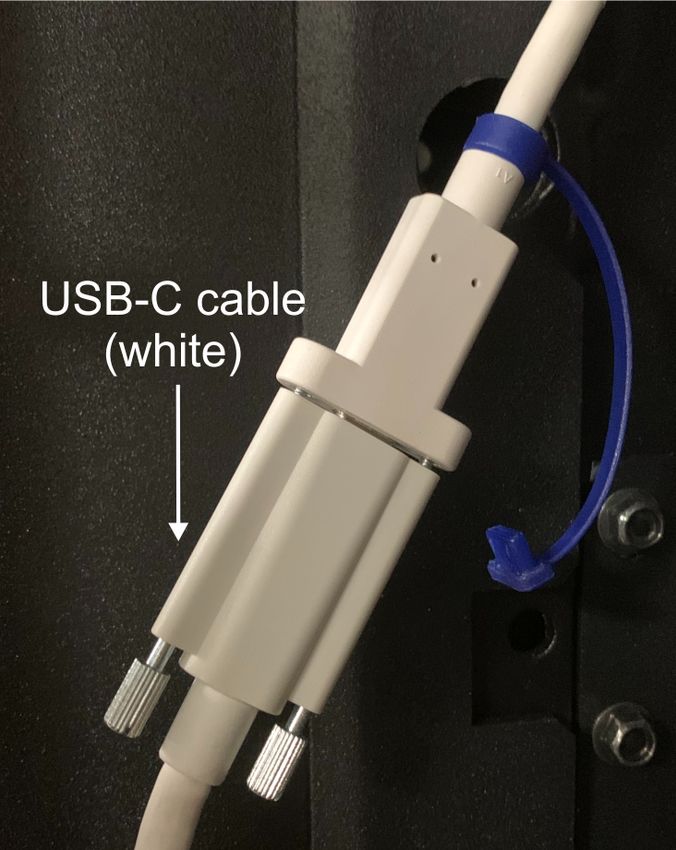
Contents

  Safety................................................................................................................... v
     Safety notices............................................................................................................................................... v
        World trade safety information...............................................................................................................v
     Laser safety information..............................................................................................................................vi
        Laser compliance................................................................................................................................... vi

  About this publication..........................................................................................vii
     Related publications...................................................................................................................................vii
     Accessibility................................................................................................................................................ vii
        Accessibility features............................................................................................................................vii
        Keyboard navigation............................................................................................................................ viii
        Consult assistive technologies............................................................................................................ viii
        IBM and accessibility........................................................................................................................... viii
     How to send your comments.....................................................................................................................viii

  Chapter 1. Safety inspection.................................................................................. 1
     Items you need............................................................................................................................................ 1
     Processor safety inspection.........................................................................................................................2
        Check the power source.........................................................................................................................4
        Checking the receptacle for wiring errors..............................................................................................4
        Checking the ground/earth path............................................................................................................ 5
        Checking the AC voltage on three phase power.................................................................................... 7
        Check the power cord.............................................................................................................................8
     Processor frame check................................................................................................................................ 9
        PDU system.............................................................................................................................................9
        Internal frame check............................................................................................................................14
     System power on....................................................................................................................................... 15
        Connecting frame power......................................................................................................................15
        Power on............................................................................................................................................... 16

  Appendix A. Notices............................................................................................ 21
     Trademarks................................................................................................................................................ 22
     Class A Notices.......................................................................................................................................... 22

                                                                                                                                                                  iii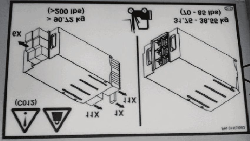
iv
Safety

Safety notices
      Safety notices may be printed throughout this guide. DANGER notices warn you of conditions or
      procedures that can result in death or severe personal injury. CAUTION notices warn you of conditions or
      procedures that can cause personal injury that is neither lethal nor extremely hazardous. Attention
      notices warn you of conditions or procedures that can cause damage to machines, equipment, or
      programs.

      DANGER notices
      The following notices appear in this Safety Inspection guide:
      DANGER: Overloading a branch circuit is potentially a fire hazard and a shock hazard under
      certain conditions. To avoid these hazards, ensure that your system electrical requirements do not
      exceed branch circuit protection requirements. Refer to the information that is provided with your
      device or the power rating label for electrical specifications. (D002)
      DANGER: If the receptacle has a metal shell, do not touch the shell until you have completed the
      voltage and grounding checks. Improper wiring or grounding could place dangerous voltage on the
      metal shell. If any of the conditions are not as described, STOP. Ensure the improper voltage or
      impedance conditions are corrected before proceeding. (D003)
      DANGER: An electrical outlet that is not correctly wired could place hazardous voltage on the
      metal parts of the system or the devices that attach to the system. It is the responsibility of the
      customer to ensure that the outlet is correctly wired and grounded to prevent an electrical shock.
      (D004)
      DANGER: Heavy equipment — personal injury or equipment damage might result if mishandled.
      (D006)

      CAUTION notices
      The following notices appear in this Safety Inspection guide:
      CAUTION: Only trained service personnel may replace this battery. The battery contains lithium.
      To avoid possible explosion, do not burn or charge the battery.
      Do not: Throw or immerse into water, heat to more than 100°C (212°F), repair or disassemble. (C002)
      CAUTION: The doors and covers to the product are to be closed at all times except for service by
      trained service personnel. All covers must be replaced and doors locked at the conclusion of the
      service operation. (C013)
      CAUTION: Ensure the building power circuit breakers are turned off BEFORE you connect the
      power cord or cords to the building power. (C023)

World trade safety information
      Several countries require the safety information contained in product publications to be presented in their
      translation. If this requirement applies to your country, a safety information booklet is included in the
      publications package shipped with the product. The booklet contains the translated safety information
      with references to the US English source. Before using a US English publication to install, operate, or
      service this product, you must first become familiar with the related safety information in the Systems
      Safety Notices, G229-9054. You should also refer to the booklet any time you do not clearly understand
      any safety information in the US English publications.

© Copyright IBM Corp. 2020                                                                                     v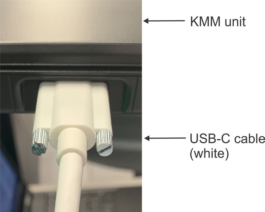
Laser safety information
      All IBM Z® (Z) and IBM® LinuxONE (LinuxONE) models can use I/O cards such as FICON®, Open Systems
      Adapter (OSA), RoCE Express, Integrated Coupling Adapter (ICA SR), zHyperLink Express, or other I/O
      features which are fiber optic based and utilize lasers (short wavelength or long wavelength lasers).

Laser compliance
      All lasers are certified in the US to conform to the requirements of DHHS 21 CFR Subchapter J for Class 1
      or Class 1M laser products. Outside the US, they are certified to be in compliance with IEC 60825 as a
      Class 1 or Class 1M laser product. Consult the label on each part for laser certification numbers and
      approval information.
      Laser Notice: U.S. FDA CDRH NOTICE if low power lasers are utilized, integrated, or offered with end
      product systems as applicable. Complies with 21 CFR 1040.10 and 1040.11 except for conformance with
      IEC 60825-1 Ed. 3., as described in Laser Notice No. 56, dated May 8, 2019.
      CAUTION: Data processing environments can contain equipment transmitting on system links with
      laser modules that operate at greater than Class 1 power levels. For this reason, never look into the
      end of an optical fiber cable or open receptacle. (C027)
      CAUTION: This product contains a Class 1M laser. Do not view directly with optical instruments.
      (C028)

vi IBM Z: 8562 Safety Inspection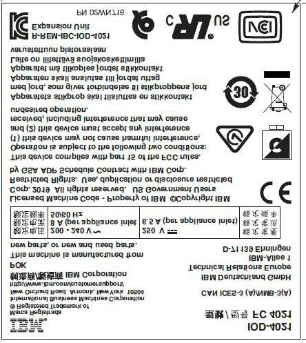
About this publication
      This guide is for service representatives only. Use this guide to perform a safety inspection of the 8562
      server.
      Unless otherwise stated, references to "8562" are applicable to IBM z15™ Model T02 and IBM
      LinuxONE III Model LT2.

      General comments
      • There might be product features represented in this manual that are not installed on the system and,
        although announced, might not be available at the time of publication.
      • There might be product features on the system that are not represented in this manual.
      • World Trade differences are identified where appropriate throughout the procedures rather than in a
        separate chapter.

Related publications
      Publications that you will find helpful and that you should use along with this publication are in the
      following list. You can access these books from Resource Link® at http://www.ibm.com/servers/
      resourcelink. Select Library on the navigation bar on the left.
      • 8562 Installation Manual, GC28-7009
      • 8562 Service Guide, GC28-7010
      • Systems Safety Notices, G229-9054

Accessibility
      Accessible publications for this product are offered in EPUB format and can be downloaded from
      Resource Link® at http://www.ibm.com/servers/resourcelink.
      If you experience any difficulty with the accessibility of any IBM Z® and IBM LinuxONE information, go to
      Resource Link at http://www.ibm.com/servers/resourcelink and click Feedback from the navigation bar
      on the left. In the Comments input area, state your question or comment, the publication title and
      number, choose General comment as the category and click Submit. You can also send an email to
      reslink@us.ibm.com providing the same information.
      When you send information to IBM, you grant IBM a nonexclusive right to use or distribute the
      information in any way it believes appropriate without incurring any obligation to you.

Accessibility features
      The following list includes the major accessibility features in IBM Z and IBM LinuxONE documentation,
      and on the Hardware Management Console and Support Element console:
      • Keyboard-only operation
      • Interfaces that are commonly used by screen readers
      • Customizable display attributes such as color, contrast, and font size
      • Communication of information independent of color
      • Interfaces commonly used by screen magnifiers
      • Interfaces that are free of flashing lights that could induce seizures due to photo-sensitivity.

© Copyright IBM Corp. 2020                                                                                        vii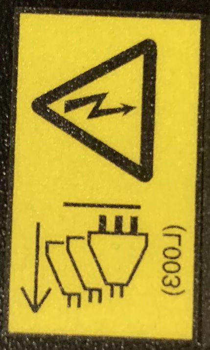
Keyboard navigation
      This product uses standard Microsoft Windows navigation keys.

Consult assistive technologies
      Assistive technology products such as screen readers function with our publications, the Hardware
      Management Console, and the Support Element console. Consult the product information for the specific
      assistive technology product that is used to access the EPUB format publication or console.

IBM and accessibility
      See http://www.ibm.com/able for more information about the commitment that IBM has to accessibility.

How to send your comments
      Your feedback is important in helping to provide the most accurate and high-quality information. Send
      your comments by using Resource Link at http://www.ibm.com/servers/resourcelink. Click Feedback on
      the navigation bar on the left. You can also send an email to reslink@us.ibm.com. Be sure to include the
      name of the book, the form number of the book, the version of the book, if applicable, and the specific
      location of the text you are commenting on (for example, a page number, table number, or a heading).

viii IBM Z: 8562 Safety Inspection
第 1 章 安全檢驗

      安全檢驗是在下列時候執行:
      •當您依 IBM® 維護合約檢查系統時
      •當您有理由懷疑裝置安全時
      •當要求 IBM 依呼叫服務,而且 IBM 近期沒有執行維護時
      •當執行變更與連接檢查時。
      如果檢驗指出無法接受的安全狀況,您必須先更正該狀況,IBM 才會提供機器維護。
      註 : 更正任何不安全狀況是硬體擁有者的責任。
      執行此檢驗時,必須特別注意下列領域:
      •配件/型號變更,以及工程變更 (EC) 升級
      •新增非 IBM 電源供應器、邏輯卡或附件
      •安全護蓋遺失
      •已移除、已褪色或遭塗抹的安全標籤
      •主要電源配件更換需求
      •其他產品安全相關項目。
      在開始之前,您必須已完成本年的一般安全或同等課程。您必須已檢閱 Electrical Safety for IBM Service
      Representatives (S229-8124) 或同等手冊。特定地理區域可能有不同的安全訓練需求,如需相關資訊,請參
      閱您所在地理區域的安全訓練需求。

需要的項目
      •IBM CE 工具箱(或同等項目)
      •針對此機型發佈的「安全工程變更」副本
      •最新機器歷程(如有可能的話)
      •Electrical Safety for IBM Service Representatives (S229-8124)
      •Fluke 8060A 數位伏特計(配件 8496278)或同等儀器
      •電工膠帶或橡膠手套
      •在美國偏好的 Suretest 檢測儀(配件 25F9715)及隔離式接地配接器(配件 00P7019)(如果可用的
       話)

© Copyright IBM Corp. 2020                                             CHT-1
處理器安全檢驗
    安全檢驗需在所有電源線上執行。
          小心 : 在開始之前,請閱讀下列聲明:

    DANGER: Overloading a branch circuit is potentially a fire hazard and a shock hazard under
    certain conditions. To avoid these hazards, ensure that your system electrical requirements do not
    exceed branch circuit protection requirements. Refer to the information that is provided with your
    device or the power rating label for electrical specifications. (D002)
    DANGER: If the receptacle has a metal shell, do not touch the shell until you have completed the
    voltage and grounding checks. Improper wiring or grounding could place dangerous voltage on the
    metal shell. If any of the conditions are not as described, STOP. Ensure the improper voltage or
    impedance conditions are corrected before proceeding. (D003)
    DANGER: An electrical outlet that is not correctly wired could place hazardous voltage on the
    metal parts of the system or the devices that attach to the system. It is the responsibility of the
    customer to ensure that the outlet is correctly wired and grounded to prevent an electrical shock.
    (D004)
    DANGER: Heavy equipment — personal injury or equipment damage might result if mishandled.
    (D006)
    CAUTION: Only trained service personnel may replace this battery. The battery contains lithium.
    To avoid possible explosion, do not burn or charge the battery.
    Do not: Throw or immerse into water, heat to more than 100°C (212°F), repair or disassemble. (C002)
    CAUTION: The doors and covers to the product are to be closed at all times except for service by
    trained service personnel. All covers must be replaced and doors locked at the conclusion of the
    service operation. (C013)
    CAUTION: Ensure the building power circuit breakers are turned off BEFORE you connect the
    power cord or cords to the building power. (C023)

    67:!"#$%&,'()*+,-./0123)4567。9:;?@AB5)C
    DEF/+G'()*@H5DE。>IJKLMN5OPQ)RSTUV,WXY)Z[\。(D002)
    MN:!"#$%&'(,*+,-./0123456789:;?@(。BCD56EFG<
    HI&'@(JKLMNO23。!"PLQRSTUOVW,XYZ[\。]^_`aEbFO23D
    cdeW9:,fghij。(D003)
    01:!"#$%&'()*+,,-./012#3456789:';782?@AB。DE
    QR FG+H%&2I(*+JK'L,MNOP#。(D004)
    67:!"#$—%&'()*+,-./012#$34。(D006)

    9::!"#$%&'()*+,-.&'78,,-./&'012345。(C023)
    Gefahr: Bei Überlastung eines Netzstromkreises besteht unter gewissen Umständen Brandgefahr
    oder das Risiko eines elektrischen Schlags. Um dies zu vermeiden, stellen Sie sicher, dass der
    elektrische Bedarf Ihres Systems die Absicherung des Netzstromkreises nicht überschreitet.
    Technische Daten zur Elektrik stehen in der Dokumentation zu der IBM Einheit oder auf dem
    Typenschild. (D002)
    Gefahr: Besitzt die Netzsteckdose ein Metallgehäuse, die Steckdose nicht berühren, bevor die
    Prüfung der Netzspannung und der Erdung erfolgreich durchgeführt wurde. Durch eine nicht
    ordnungsgemäß angeschlossene Steckdose oder durch nicht ordnungsgemäße Erdung können
    am Metallgehäuse gefährliche Berührungsspannungen auftreten. Ist die Prüfung nicht
    erfolgreich, die Arbeit ABBRECHEN. Die korrekte Netzspannung und Impedanz herstellen,
    bevor die Installation fortgesetzt wird. (D003)

CHT-2 IBM Z: 8562 安全檢驗
Gefahr: Bei nicht ordnungsgemäß angeschlossener Netzsteckdose können an Metallteilen des
Systems oder an angeschlossenen Einheiten gefährliche Berührungsspannungen auftreten.
Für den ordnungsgemäßen Zustand der Steckdose ist der Betreiber verantwortlich. (D004)
Gefahr: Schwere Einheit — Gefahr von Verletzungen oder Beschädigung der Einheit
bei unsachgemäßer Behandlung. (D006)
Vorsicht: Die Türen und Abdeckungen müssen immer geschlossen sein. Sie dürfen nur von
ausgebildetem Kundendienstpersonal geöffnet werden. Nach Abschluss der Wartung müssen
wieder alle Abdeckungen eingesetzt und alle Türen geschlossen werden. (C013)
Vorsicht: Die Sicherungsautomaten der Gebäudeinstallation VOR dem Anschließen der
Netzkabel an die Stromversorgung des Gebäudes auftrennen. (C023)
第 1 章 安全檢驗 CHT-3檢查電源
註 : 安全檢驗需在所有電源線上執行。
PDU 電源
__ 1. 執行下列其中一項動作來拔除 8562 的電源:
•拔除電源
•開啟供應斷路器
•拔除 PDU 電源線。
__ 2. 如果系統沒有斷電,請參閱 8562 服務手冊、GC28-7010,對問題進行疑難排解。
檢查插座是否發生佈線錯誤
使用下列步驟,測試客戶用來提供電力給機架的所有插座:
註 : 客戶所提供的電壓只有 AC。
在客戶用來提供電力給機架的所有插座上,執行下列 AC 電壓檢查。
__ 1. 驗證是否所有牆壁開關都設為關閉位置。
__ 2. PDU 電源
•請仔細探測 PDU 插座,以驗證是否已關閉所有電源。
__ 3. 使用 CE 計量儀進行檢查,確保從插座接地端到大廈接地端(水管、大廈用鋼等)無 AC 電壓。接地的
高架地板可能不是可接受的大廈接地端。如果下列情況為 true,則接地的高架地板不可接受:
•它連結至大廈用鋼
•它採用螺栓式縱梁設計
•縱梁系統未腐蝕。
若為金屬插座機殼或具有金屬元件的殼體,請檢查從插座接地插腳到金屬之間是否無 AC 電壓。
CHT-4 IBM Z: 8562 安全檢驗檢查接地路徑
使用程序 A 或程序 B,在客戶用來提供電力給機架的所有插座上,執行接地路徑檢查。在美國,如果有正確
的設備,偏好的方法是程序 A。
程序 A(美國偏好該程序)
此程序使用下列任何一項,檢查接地電阻為 1 歐姆或更小值的插座接地插腳:
•SureTest Model 61-164 Circuit Analyzer P/N 39X8928(含配件):
– SureTest Model 61-175 Ground Continuity Adapter P/N 39X8929
– SureTest Model 61-183 Alligator Clip Adapter P/N 39X8930(用於測試 208/220 伏特)
•SureTest Model ST-1D with IG 配接卡 P/N 25F9715
•SureTest Model ST-1THD 檢測儀 P/N 25F9722
•ECOS C7106 檢測儀(確保 ECOS 檢測儀是 Model C7106)
單字「檢測儀」的使用:
在下列程序中,單字「檢測儀」是指上面列出的任何裝置。請務必遵循檢測儀製造商的指示,來執行電子
測試。
4 pins 5 pins
L2
L3 L2
Neutral L1
L1 L3
Ground/Earth Ground/Earth
__ 1. 在要測試的插座附近找到「即時」插座。選取的插座必須與要測試的插座衍生自同一電源。
小心 : 請勿使用客戶的具有 GFCI 保護的插座。
__ 2. 將檢測儀插入插座。
__ 3. 依照檢測儀指示中的指示來執行電阻測試。
__ 4. 拔出檢測儀。
__ 5. 將檢測儀插入接地測試探針。
__ 6. 將此探針的彈簧夾連接至所要測試的插座接地插腳。
__ 7. 將檢測儀重新插入至插座(可能需要延長線)。
__ 8. 重複檢測儀用法說明中指定的測試,尋找 1 歐姆或更小值的指示。
__ 9. 如果接頭有金屬殼體或金屬元件,請從牆壁插座中拔出檢測儀,並將彈簧夾重新連接至金屬,然後重
新插入檢測儀並重複測試。如需相關資訊,請參閱 IBM 服務人員安全手冊,或適用於您所在地理區域
的同等說明文件。
第 1 章 安全檢驗 CHT-5程序 B
此程序使用 CE 計量儀,檢查接地電阻為 1 歐姆或更小值的插座接地插腳:
牆壁開關應該關閉。
4 pins 5 pins
L2
L3 L2
Neutral L1
L1 L3
Ground/Earth Ground/Earth
__ 1. 使用 CE 計量儀,測量從插座接地插腳到大廈接地端的電阻。該讀數必須為 1 歐姆或更小的值。
__ 2. 若為金屬插座機殼或具有金屬元件的殼體,還需測量從插座接地插腳到金屬的電阻。此讀數應該為 0.1
歐姆或更小的值。
註 : 如果大廈接地電路中有洩漏電流,數位計量儀可能會顯示不穩定的電阻讀數。如果讀取大於 1 歐
姆(或在 1 以上波動),則停止。
a. 讓客戶的電工沿接地路徑往回檢查到電源。
b. 如果電工更正問題,請重新測試。
c. 如果問題持續存在,並且電工已確認從插座到電源的接地可接受:
__ 1) 在安裝報告中記錄電工的發現項目
__ 2) 通知支援 IPR 該帳戶
CHT-6 IBM Z: 8562 安全檢驗檢查三相電源上的 AC 電壓
4 pins 5 pins
L2
L3 L2
Neutral L1
L1 L3
Ground/Earth Ground/Earth
在客戶用來提供電力給機架的所有牆壁開關上,執行下列 AC 電壓檢查。
__ 1. 驗證是否所有牆壁開關都設為開啟位置。
__ 2. 測量客戶提供的電壓,並在這裡寫下電壓。如果電壓超出可接受的範圍(請參閱下方),則建議客戶
讓獲授權的電工更正問題。
_____________ V AC
__ 3. 可接受的電壓範圍是 50 或 60 Hz,三相電源供應器如下所示:
PDU 電源
•30A、200-240 V AC
•32A、380-415 V AC
__ 4. 關閉牆壁開關。
第 1 章 安全檢驗 CHT-7檢查電源線
在客戶用來提供電力給機架的所有電源線上,執行下列檢查。
註 : 如果電源線是直接連接至電源,請跳過步驟 2 及 3。
PDU 電源
__ 1. 檢查所有電源線上是否有破損、絕緣損壞或插腳燒壞。確保可拔出插頭完全插入 PDU 中。
請驗證是否所有三角形連接的 PDU 電源線都具有下列標籤 (L036) 並且可讀取:
CAUTION:
此電源線使用不想要在供電情況下配對、取消配對或移動的應用裝置耦合器。每當電源線插入、拔出
或未連接產品時,都應該關閉應用裝置耦合器的電壓供應(例如:供電端插頭或分支斷路器)。
(L036)
__ 2. 測量從斷開的電源線接地插腳至 PDU 之機架接地端的電阻。此讀數必須為 0.1 歐姆或更小的值。
__ 3. 檢查緊鬆件,確保其正確安裝並系緊。
CHT-8 IBM Z: 8562 安全檢驗處理器機架檢查
PDU 系統
在裝置正面:
__ 1. 檢查下列項目:
__ •檢查蓋板是否損壞或缺失。
__ •檢查所有蓋板上是否有鋒利邊緣。
__ •確保安裝的配件上已正確固定所有魔術沾帶。
FRONT
Trenton Systems
RW DVD DISC
12
1 2 3 4 5 !
Trenton Systems
RW DVD DISC
12
1 2 3 4 5 !
Fan1 Fan2
Fan3
I/O Fan4
Fan5 Fan6
Fan1 Fan2
Fan3
I/O Fan4
Fan5 Fan6
FAN1
FAN1
CPC
FAN2
FAN2
PPC1
PPC1
FAN3
FAN3 FAN4
FAN4
PPC2
PPC2
FAN5
FAN5
FAN1
FAN1
CPC
FAN2
FAN2
PPC1
PPC1
FAN3
FAN3 FAN4
FAN4
PPC2
PPC2
FAN5
FAN5
Fan1 Fan2
Fan3
I/O Fan4
Fan5 Fan6
A
__ 2. 確保下列標籤完備,而且清晰易辨認。
__ •穿過底端的傾斜警告標籤。
__ •顯示在每一個 PCIe+ I/O 抽換匣上的大重量警告及電壓警告。必須移除 PCIe+ I/O 抽換匣邊框,
才能檢視這些安全標籤。
第 1 章 安全檢驗 CHT-9__ 3. 確保機架上貼著指示您不要同時拉出多個抽換匣的標籤,如圖所示。這些標籤出現在機架上的多個位
置;在 PCIe+ I/O 抽換匣、 CPC 處理器抽換匣及「支援元素」旁邊。
__ 4. 確保機體完整性標籤完備,而且清晰易辨認。該標籤 (L031) 指示您在維修完成後立即重新安裝所有蓋
板、邊框、蓋子及/或門。此標籤顯示 PCIe+ I/O 及 CPC 抽換匣邊框內部。
(L031)
PN 02WN393
CHT-10 IBM Z: 8562 安全檢驗在裝置背面 (PDU):
__ 1. 檢查下列項目:
__ •檢查蓋板是否損壞或缺失。
__ •檢查所有蓋板上是否有鋒利邊緣。
__ •確保在安裝的配件上,所有指擰螺絲就位並擰緊。
REAR
ac ac
dc dc
750w 750w
ac ac
dc dc
750w 750w
IPC PSU I P P I
IPC PSU
P S S P
C U U C
1 1 2 2
L
FSP G
L
G
FSP
0
1
1
1
L
Express 4s 10G LR L Express 4s 10G SR
PCI G
0
G PCI
1
2
2
Express 4s 1G LX L
L
Express 4s 1G SX
PCI G
0
G PCI
1
3
3
J01
J02
Express 8s 10KM LX L Express 8s SX
L
PCI G
0
G PCI
4 1
4
J00
Crypto Express 5s L zCOMP
PCI G L
G
PCI
0
5 1
5
Switch L
L
Switch
G
0 G
6 1
6
Express 5s 10G LR L L Express 5s 10G SR
PCI G
0
G
1
PCI
7 7
Express 5s 1G LX Express 5s 1G SX
J01
L L
G G
PCI 0 1 PCI
8 8
Express 16s 10KM LX L L Express 16s SX
G G
PCI 0 1 PCI
9 9
Express 5s 1000 baseT ROCE
PCI PCI
IPC PSU I P P I
IPC PSU
P S S P
C U U C
1 1 2 2
L
FSP G
L
G
FSP
0
1
1
1
Express 4s 10G LR L
L Express 4s 10G SR
PCI G
0
G PCI
1
2
2
Express 4s 1G LX L
L
Express 4s 1G SX
PCI G
PCI
J01 J01
J02 J02
G
0
1
3
3
Express 8s 10KM LX L Express 8s SX
L
PCI G PCI
J00
G
0
4 1
4
Crypto Express 5s L zCOMP
PCI G L
G
PCI
0
5 1
5
Switch L
L
Switch
G
0 G
6 1
6
Express 5s 10G LR L L Express 5s 10G SR
PCI G G
PCI
J01
0 1
7 7
Express 5s 1G LX Express 5s 1G SX
J01
L L
G G
PCI 0 1 PCI
8 8
Express 16s 10KM LX L L Express 16s SX
G G
PCI 0 1 PCI
9 9
Express 5s 1000 baseT ROCE
PCI PCI
J02
J00
J01
FRU FRU FRU FRU FRU FRU FRU FRU FRU FRU FRU FRU
PSU PSU PSU PSU
J01
J02
J00
FRU FRU FRU FRU FRU FRU FRU FRU FRU FRU FRU FRU
PSU PSU PSU PSU
J01
IPC PSU I P P I
IPC PSU
P S S P
C U U C
1 1 2 2
L
FSP G
L
G
FSP
0
1
1
1
L
Express 4s 10G LR L Express 4s 10G SR
PCI G
0
G PCI
1
2
2
Express 4s 1G LX L
L
Express 4s 1G SX
PCI G
0
G PCI
1
3
3
J01
J02
Express 8s 10KM LX L Express 8s SX
L
PCI G
0
G PCI
4 1
4
Crypto Express 5s L zCOMP
PCI G L
G
PCI
0
5 1
5
Switch L
L
Switch
G
0 G
1
J01
J02
6
6
Express 5s 10G LR L L Express 5s 10G SR
J00
PCI G
0
G
1
PCI
7 7
Express 5s 1G LX Express 5s 1G SX
J01
L L
G G
PCI 0 1 PCI
8 8
Express 16s 10KM LX L L Express 16s SX
G G
PCI 0 1 PCI
9 9
Express 5s 1000 baseT ROCE
PCI PCI
J01
A
__ 2. 確保下列標籤完備,而且清晰易辨認。
__ •高洩漏警告(標籤 P/N 01KL318)- 機架的每一端 4 個標籤(總計 8 個)
__ •多條電源線,類似於安全標示標籤 L003 - 機架的每一端 4 個標籤(總計 8 個)
__ •讀取手冊 - 機架的每一端 1 個標籤,大約從頂端 2 英尺(總計 2 個)
第 1 章 安全檢驗 CHT-11__ •高洩漏警告(標籤 P/N 01KL395),位於機架右下方。
__ 3. 確保 8562 機型認證標籤完備,而且清晰易辨認。
標籤 (P/N 03FM610) 位於機架背面的右側。
CHT-12 IBM Z: 8562 安全檢驗__ 4. 在已安裝的每個 PCIe+ I/O 抽換匣上,確保下列標籤完備,而且清晰易辨認。
__ •每條電源線的電力額定值 (A):
__ – 200-240 V AC 單相,8A, 50/60 Hz(每個應用裝置入口)
__ – 250 V DC,6.5A(每個應用裝置入口)
__ •電擊危險 (B)
__ •多條電源線 (C) 與 (D)
__ •多條電源線警 (E),類似於安全標示標籤 L003
A B C D E
200 - 240 V 250 V
8 A (per appliance inlet 6.5 A (per appliance inlet)
50/60 Hz
第 1 章 安全檢驗 CHT-13內部機架檢查
__ 1. 檢查非 IBM 變更或連接。若有的話,請完成表單 R-009 (非 IBM 變更/連接調查)。
__ 2. 檢查是否有煙霧或水侵蝕,以及是否有生鏽或其他污染。
__ 3. 核實所有蓋板均已安裝,而且沒有遺失螺絲或墊圈。
__ 4. 檢查是否有鋒利邊緣。
機器安全變更
__ 1. 檢查是否有任何針對此機型發佈的「安全工程變更」。
__ 2. 檢查機器,確保所有安全變更均已安裝。
__ 3. 訂購任何缺失的安全變更或必須更換的標籤,並儘快予以安裝。
__ 4. 更新機器歷程(如果可用的話),以顯示所有已安裝的安全變更。
CHT-14 IBM Z: 8562 安全檢驗系統加電
連接機架電源
PDU 電源
__ 1. 讓客戶開啟斷路器,以從系統移除電源。
__ 2. 將所有的系統電源線連接至電源。
請驗證是否所有三角形連接的 PDU 電源線都具有下列標籤 (L036) 並且可讀取:
CAUTION:
此電源線使用不想要在供電情況下配對、取消配對或移動的應用裝置耦合器。每當電源線插入、拔出
或未連接產品時,都應該關閉應用裝置耦合器的電壓供應(例如:供電端插頭或分支斷路器)。
(L036)
__ 3. 請客戶重設系統的斷路器。
註 : 對系統供應電源,所有元件(CPC 抽換屜、PCIe+ I/O 抽換屜及支援元素)的指示燈都會亮起。
第 1 章 安全檢驗 CHT-15開啟電源
準備精簡 KMM(鍵盤、監視器、滑鼠)
完成下列程序,以組合精簡 KMM(鍵盤、監視器、滑鼠)支援硬體:
__ 1. 從 KMM 儲存體方框中擷取精簡 KMM。
compact
KMM storage
box
__ 2. 從 KMM 支架臂 (P/N 02WN481) 中,鬆開 KMM 機架托架 (P/N 02WN899) 及 KMM 裝載托架 (P/N
02WN992) 的螺絲。
KMM support
arm
KMM mounting
bracket
KMM frame
bracket
__ 3. 將 KMM 機架托架安裝在內部機架的左側或右側。使用連接的螺絲,將托架固定在內部機架上 EIA
24 處的三個現有孔的一個孔中。
attach KMM
frame bracket
__ 4. 使用 2 個連接螺絲,將 KMM 裝載托架固定到 KMM 支架臂上。
__ 5. 使用 2 個連接螺絲,將 KMM 支架臂固定到 KMM 機架托架上。
CHT-16 IBM Z: 8562 安全檢驗__ 6. 將精簡 KMM 放在裝載托架上,將 KMM 拉向您以固定。
__ 7. 開啟精簡 KMM 並傾斜顯示器以調整到可用位置。
__ 8. 從 KMM 儲存體方框中擷取白色 USB-C 纜線 (P/N 02EC951);提供了 2 條纜線(1 條備用)。
__ 9. 如果將 KMM 固定至機架正面,請將白色 USB-C 纜線插入主要介面配接卡,如下所示。 然後,跳至
步驟 第 18 頁的『11』。
第 1 章 安全檢驗 CHT-17__ 10. 如果將 KMM 固定至機架背面,請執行下列動作:
a. 從 USB-C 連接器移除藍色保護蓋。
b. 將白色 USB-C 纜線插入連接器。
__ 11. 將白色 USB-C 纜線的另一端插入精簡 KMM 上的埠。
CHT-18 IBM Z: 8562 安全檢驗第 1 章 安全檢驗 CHT-19
開啟電源
     __ 1. PSU 上的綠色 PSU PWR LED 燈將持續亮起。
     __ 2. 等待「主要支援元素登入」視窗出現。
          a. 如果替代支援元素視窗出現,請按一下介面配接卡前端上未亮起的選項按鈕,以回到「主要支援
             元素」。
           註 : 當選取了相關的「支援元素」時,「支援元素」選項按鈕會亮起。 這容許您隨時知曉哪個
           「支援元素」正在與精簡 KMM 進行通訊。

          b. 如果安裝了「硬體管理應用裝置」配件 (FC 0100),則「硬體管理應用裝置 HMC 登入」視窗將出
             現。
            1) 登入「硬體管理應用裝置 HMC」。
            2) 從「作業索引」中,按一下虛擬支援元素管理作業。
            3) 從此項作業中,按一下啟動 SE 虛擬機器,以啟動「虛擬支援元素」。
            4) 按一下顯示 SE 主控台。等待「主要支援元素登入」視窗出現。
            5) 如果替代支援元素視窗出現,請按一下 KVM 上的頂部按鈕,以切換至其他「硬體管理應用裝
               置 HMC」。 然後,重複步驟 2b 以啟動「主要支援元素」。
     __ 3. 在「主要支援元素登入」視窗上,執行下列動作:
         •在使用者名稱欄位中鍵入 SERVICE。
         •在密碼欄位中鍵入 SERVMODE。
     __ 4. 按一下系統管理。
     __ 5. 選取系統名稱。
     __ 6. 按一下服務。
     __ 7. 按一下服務狀態。
     __ 8. 如果已啟用「服務狀態」,則跳至步驟 第 20 頁的『9』。否則,請完成下列步驟:
          a. 必要的話,選取勾選框。
          b. 按一下選項。
          c. 按一下啟用服務狀態。
          d. 按一下儲存。
          e. 按一下是。
          f. 如果適用,請按一下確定。
          g. 按一下取消以關閉。
     __ 9. 按一下回復。
    __ 10. 按一下開啟電源。
    __ 11. 順利開啟系統電源後,按一下確定以關閉視窗。

CHT-20 IBM Z: 8562 安全檢驗
Chapter 1. Safety inspection
A safety inspection is performed:
• When you inspect the system for an IBM maintenance agreement
• When there is reason to question the unit safety
• When IBM per call service is requested and no service has recently been performed by IBM
• When an alterations and attachments review is performed.
If the inspection indicates an unacceptable safety condition, the condition must be corrected before IBM
provides service to the machine.
Note: The correction of any unsafe condition is the responsibility of the owner of the hardware.
While performing this inspection, special attention must be given to these areas:
• Feature/model changes and Engineering Change (EC) upgrades
• Additions of non-IBM power supplies, logic cards, or attachments
• Missing safety covers
• Removed, faded, or painted-over safety labels
• Primary power parts replacement requirements
• Other product safety-related items.
Before you start, you must have completed the General Safety or equivalent course for this year.
Reviewed the Electrical Safety for IBM Service Representatives, S229-8124, or equivalent handbook.
Certain geographies might have different safety training requirements, see your safety training
requirements within your geography for more information.
Items you need
• An IBM CE toolkit (or equivalent)
• Copies of Safety Engineering Changes released for this machine type.
• Latest machine history, if possible
• Electrical Safety for IBM Service Representatives, S229-8124
• A Fluke 8060A digital voltmeter (part 8496278) or equivalent
• Electrical tape or rubber gloves
• A Suretest tester (part 25F9715) and Isolated Earth Adapter (part 00P7019), preferred in the United
States, if available
© Copyright IBM Corp. 2020 1Processor safety inspection
Safety inspection is performed on all power cords.
Attention: Read the following notices before beginning:
DANGER: Overloading a branch circuit is potentially a fire hazard and a shock hazard under
certain conditions. To avoid these hazards, ensure that your system electrical requirements do not
exceed branch circuit protection requirements. Refer to the information that is provided with your
device or the power rating label for electrical specifications. (D002)
DANGER: If the receptacle has a metal shell, do not touch the shell until you have completed the
voltage and grounding checks. Improper wiring or grounding could place dangerous voltage on the
metal shell. If any of the conditions are not as described, STOP. Ensure the improper voltage or
impedance conditions are corrected before proceeding. (D003)
DANGER: An electrical outlet that is not correctly wired could place hazardous voltage on the
metal parts of the system or the devices that attach to the system. It is the responsibility of the
customer to ensure that the outlet is correctly wired and grounded to prevent an electrical shock.
(D004)
DANGER: Heavy equipment — personal injury or equipment damage might result if mishandled.
(D006)
CAUTION: Only trained service personnel may replace this battery. The battery contains lithium.
To avoid possible explosion, do not burn or charge the battery.
Do not: Throw or immerse into water, heat to more than 100°C (212°F), repair or disassemble. (C002)
CAUTION: The doors and covers to the product are to be closed at all times except for service by
trained service personnel. All covers must be replaced and doors locked at the conclusion of the
service operation. (C013)
CAUTION: Ensure the building power circuit breakers are turned off BEFORE you connect the
power cord or cords to the building power. (C023)
67:!"#$%&,'()*+,-./0123)4567。9:;?@AB5)C
DEF/+G'()*@H5DE。>IJKLMN5OPQ)RSTUV,WXY)Z[\。(D002)
MN:!"#$%&'(,*+,-./0123456789:;?@(。BCD56EFG<
HI&'@(JKLMNO23。!"PLQRSTUOVW,XYZ[\。]^_`aEbFO23D
cdeW9:,fghij。(D003)
01:!"#$%&'()*+,,-./012#3456789:';782?@AB。DE
QR FG+H%&2I(*+JK'L,MNOP#。(D004)
67:!"#$—%&'()*+,-./012#$34。(D006)
9::!"#$%&'()*+,-.&'78,,-./&'012345。(C023)
Gefahr: Bei Überlastung eines Netzstromkreises besteht unter gewissen Umständen Brandgefahr
oder das Risiko eines elektrischen Schlags. Um dies zu vermeiden, stellen Sie sicher, dass der
elektrische Bedarf Ihres Systems die Absicherung des Netzstromkreises nicht überschreitet.
Technische Daten zur Elektrik stehen in der Dokumentation zu der IBM Einheit oder auf dem
Typenschild. (D002)
2 IBM Z: 8562 Safety InspectionGefahr: Besitzt die Netzsteckdose ein Metallgehäuse, die Steckdose nicht berühren, bevor die
Prüfung der Netzspannung und der Erdung erfolgreich durchgeführt wurde. Durch eine nicht
ordnungsgemäß angeschlossene Steckdose oder durch nicht ordnungsgemäße Erdung können
am Metallgehäuse gefährliche Berührungsspannungen auftreten. Ist die Prüfung nicht
erfolgreich, die Arbeit ABBRECHEN. Die korrekte Netzspannung und Impedanz herstellen,
bevor die Installation fortgesetzt wird. (D003)
Gefahr: Bei nicht ordnungsgemäß angeschlossener Netzsteckdose können an Metallteilen des
Systems oder an angeschlossenen Einheiten gefährliche Berührungsspannungen auftreten.
Für den ordnungsgemäßen Zustand der Steckdose ist der Betreiber verantwortlich. (D004)
Gefahr: Schwere Einheit — Gefahr von Verletzungen oder Beschädigung der Einheit
bei unsachgemäßer Behandlung. (D006)
Vorsicht: Die Türen und Abdeckungen müssen immer geschlossen sein. Sie dürfen nur von
ausgebildetem Kundendienstpersonal geöffnet werden. Nach Abschluss der Wartung müssen
wieder alle Abdeckungen eingesetzt und alle Türen geschlossen werden. (C013)
Vorsicht: Die Sicherungsautomaten der Gebäudeinstallation VOR dem Anschließen der
Netzkabel an die Stromversorgung des Gebäudes auftrennen. (C023)
Chapter 1. Safety inspection 3Check the power source
Note: The safety inspection is performed on all power cords.
PDU power
__ 1. Remove power from the 8562 by doing one of the following:
• Removing the power source
• Opening the supply circuit breakers
• Removing the power cords from the PDUs.
__ 2. If the system does not power off, see 8562 Service Guide, GC28-7010 to troubleshoot the problem.
Checking the receptacle for wiring errors
Test all receptacles the customer uses to supply power to the frame using the following steps:
Note: The customer supplied voltage is AC only.
Perform the following AC voltage checks on all of the receptacles that the customer uses to supply power
to the frame.
__ 1. Verify that the wall breaker is set to the OFF position.
__ 2. PDU power
• Carefully probe the PDU outlets to verify that all power is turned off.
__ 3. Using the CE meter, check to be sure that there is no AC voltage from receptacle ground/earth to
building ground/earth (water pipe, building steel, etc.). Grounded raised floors might not be an
acceptable building ground/earth. A grounded raised floor is acceptable if the following is true:
• It is bonded to building steel
• It is a bolted stringer design
• The stringer system is not corroded.
For metal receptacle shells or shells with metal components, check for no AC voltage from the
receptacle ground/earth pin to the metal.
4 IBM Z: 8562 Safety InspectionChecking the ground/earth path
Perform the ground/earth path checks using either Procedure A or Procedure B on all receptacles the
customer uses to supply power to the frame. If the correct equipment is available, Procedure A is the
preferred method in the United States.
Procedure A (preferred in the USA)
This procedure checks for a ground/earth impedance of 1 ohm or less at the receptacle ground/earth pin
using any of the following:
• SureTest Model 61-164 Circuit Analyzer, P/N 39X8928 with accessories:
– SureTest Model 61-175 Ground Continuity Adapter, P/N 39X8929
– SureTest Model 61-183 Alligator Clip Adapter, P/N 39X8930 (for testing 208/220 volts)
• SureTest Model ST-1D with IG adapter, P/N 25F9715
• SureTest Model ST-1THD tester, P/N 25F9722
• ECOS C7106 tester (make sure the ECOS tester is Model C7106)
Use of the word "tester":
In the following procedure, the word "tester" refers to any of the devices listed above. Be certain to
follow the tester manufacturer’s instructions to perform the electrical tests.
4 pins 5 pins
L2
L3 L2
Neutral L1
L1 L3
Ground/Earth Ground/Earth
__ 1. Locate a "live" outlet near the receptacle that will be tested. The outlet selected must be derived
from the same power source as the receptacle to be tested.
Attention: Do not use a customer's receptacle with GFCI protection.
__ 2. Insert the tester into the outlet.
__ 3. Perform the impedance test as indicated in the instructions for the tester.
__ 4. Unplug the tester.
__ 5. Plug the tester into the ground test probe.
__ 6. Attach the alligator clip from this probe to the ground/earth pin of the receptacle to be tested.
__ 7. Reinsert the tester into the receptacle (you might need an extension cord).
__ 8. Repeat the test as specified in the tester instructions, looking for an indication of 1 ohm or less.
__ 9. If the connector has a metal shell or metal components, unplug the tester from the wall receptacle
and reconnect the alligator clip to the metal, then reinsert the tester and repeat the test. For more
information, refer to Safety Manual for IBM Service Personnel, or equivalent documentation for your
geography.
Chapter 1. Safety inspection 5Procedure B
This procedure checks for a ground/earth resistance of 1 ohm or less at the receptacle ground/earth pin
using the CE meter.
The wall breaker should be OFF.
4 pins 5 pins
L2
L3 L2
Neutral L1
L1 L3
Ground/Earth Ground/Earth
__ 1. Using the CE meter, measure the resistance from the ground/earth pin of the receptacle to building
ground/earth. The reading should be 1 ohm or less.
__ 2. For metal receptacle shells or shells with metal components, also measure the resistance from the
ground/earth pin of the receptacle to the metal. This reading should be 0.1 ohm or less.
Note: Digital meters might give unstable resistance readings if leakage current is flowing in the
building ground/earth circuit. If the reading is above (or is fluctuating above) 1 ohm, STOP.
a. Have the customer's electrician inspect the ground path back to the power source.
b. If the electrician corrects the problem, retest.
c. If the problem persists and the electrician has confirmed that the ground from the receptacle
back to the power source is acceptable:
__ 1) Document the electrician’s finding in the installation report
__ 2) Notify the supporting IPR for the account
6 IBM Z: 8562 Safety InspectionChecking the AC voltage on three phase power
4 pins 5 pins
L2
L3 L2
Neutral L1
L1 L3
Ground/Earth Ground/Earth
Perform the following AC voltage check on all of the wall breakers that the customer uses to supply power
to the frame.
__ 1. Verify that the wall breaker is set to the ON position.
__ 2. Measure the customer supplied voltage and write the voltage here. If the voltage is outside the
acceptable range (see below), advise the customer to have a licensed electrician correct the
problem.
_____________ V AC
__ 3. The acceptable voltage range for 50 or 60 Hz, three phase power supplies is as follows:
PDU power
• 30A, 200-240 V AC
• 32A, 380-415 V AC
__ 4. Turn the wall breaker OFF.
Chapter 1. Safety inspection 7Check the power cord
Perform the following check on all of the power cords that the customer uses to supply power to the
frame.
Note: Skip steps 2 and 3 if the power cord is wired directly to the power source.
PDU power
__ 1. Check all power cords for damage, broken insulation, or burned pins. Ensure that the removable
plug is fully inserted in the PDU.
Verify that all delta-connected PDU power cords have the following label (L036) in place and
readable:
CAUTION:
This line cord uses an appliance coupler that is not intended to be mated, unmated, or moved while
electrically active. Supply voltage to appliance coupler should be turned off (for example: by the
supply side plug or branch circuit breaker) whenever the line cord is being plugged, unplugged, or is
not attached to the product. (L036)
__ 2. Measure the resistance from the earth pin of the disconnected power cord to frame earth of the
PDU. The reading must be 0.1 ohms or less.
__ 3. Check the strain relief clamp to ensure that it is correctly installed and tightly fastened.
8 IBM Z: 8562 Safety InspectionProcessor frame check
PDU system
At the FRONT of the unit:
__ 1. Check the following:
__ • Check for damaged or missing covers.
__ • Check all covers for sharp edges.
__ • Ensure that all fasteners are properly set on installed features.
FRONT
Trenton Systems
RW DVD DISC
12
1 2 3 4 5 !
Trenton Systems
RW DVD DISC
12
1 2 3 4 5 !
Fan1 Fan2
Fan3
I/O Fan4
Fan5 Fan6
Fan1 Fan2
Fan3
I/O Fan4
Fan5 Fan6
FAN1
FAN1
CPC
FAN2
FAN2
PPC1
PPC1
FAN3
FAN3 FAN4
FAN4
PPC2
PPC2
FAN5
FAN5
FAN1
FAN1
CPC
FAN2
FAN2
PPC1
PPC1
FAN3
FAN3 FAN4
FAN4
PPC2
PPC2
FAN5
FAN5
Fan1 Fan2
Fan3
I/O Fan4
Fan5 Fan6
A
__ 2. Ensure that the following labels are in place and readable.
__ • The tilt warning label that runs across the bottom.
__ • The heavy weight warning and voltage warning that appear on each of the PCIe+ I/O drawers.
The PCIe+ I/O drawer bezel must be removed to view these safety labels.
Chapter 1. Safety inspection 9__ 3. Ensure that the label instructing you not to pull out multiple drawers at the same time appears on
the frame as shown. These labels appear in several locations on the frame; next to the PCIe+ I/O
drawer(s), CPC processor drawer(s), and Support Elements.
__ 4. Ensure that the enclosure integrity label is in place and readable. The label (L031) instructs you to
promptly reinstall all covers, bezels, lids, and/or doors immediately after service completion. This
label appears on the inside of the PCIe+ I/O and CPC drawer bezels.
(L031)
PN 02WN393
10 IBM Z: 8562 Safety InspectionAt the REAR of the unit (PDU):
__ 1. Check the following:
__ • Check for damaged or missing covers.
__ • Check all covers for sharp edges.
__ • Ensure that all thumb screws are in place and tightly fastened on installed features.
REAR
ac ac
dc dc
750w 750w
ac ac
dc dc
750w 750w
IPC PSU I P P I
IPC PSU
P S S P
C U U C
1 1 2 2
L
FSP G
L
G
FSP
0
1
1
1
L
Express 4s 10G LR L Express 4s 10G SR
PCI G
0
G PCI
1
2
2
Express 4s 1G LX L
L
Express 4s 1G SX
PCI G
0
G PCI
1
3
3
J01
J02
Express 8s 10KM LX L Express 8s SX
L
PCI G
0 G PCI
4 1
4
J00
Crypto Express 5s L zCOMP
PCI G L
G
PCI
0
5 1
5
Switch L
L
Switch
G
0 G
6 1
6
Express 5s 10G LR L L Express 5s 10G SR
PCI G
0
G
1
PCI
7 7
Express 5s 1G LX Express 5s 1G SX
J01
L L
G G
PCI 0 1 PCI
8 8
Express 16s 10KM LX L L Express 16s SX
G G
PCI 0 1 PCI
9 9
Express 5s 1000 baseT ROCE
PCI PCI
IPC PSU I P P I
IPC PSU
P S S P
C U U C
1 1 2 2
L
FSP G
L
G
FSP
0
1
1
1
Express 4s 10G LR L Express 4s 10G SR
L
PCI G
0
G PCI
1
2
2
Express 4s 1G LX L
L
Express 4s 1G SX
PCI G
PCI
J01 J01
J02 J02
G
0
1
3
3
Express 8s 10KM LX L Express 8s SX
L
PCI G PCI
J00
G
0
4 1
4
Crypto Express 5s L zCOMP
PCI G L
G
PCI
0
5 1
5
Switch L
L
Switch
G
0 G
6 1
6
Express 5s 10G LR L L Express 5s 10G SR
PCI G G
PCI
J01
0 1
7 7
Express 5s 1G LX Express 5s 1G SX
J01
L L
G G
PCI 0 1 PCI
8 8
Express 16s 10KM LX L L Express 16s SX
G G
PCI 0 1 PCI
9 9
Express 5s 1000 baseT ROCE
PCI PCI
J02
J00
J01
FRU FRU FRU FRU FRU FRU FRU FRU FRU FRU FRU FRU
PSU PSU PSU PSU
J01
J02
J00
FRU FRU FRU FRU FRU FRU FRU FRU FRU FRU FRU FRU
PSU PSU PSU PSU
J01
IPC PSU I P P I
IPC PSU
P S S P
C U U C
1 1 2 2
L
FSP G
L
G
FSP
0
1
1
1
L
Express 4s 10G LR L Express 4s 10G SR
PCI G
0
G PCI
1
2
2
Express 4s 1G LX L
L
Express 4s 1G SX
PCI G
0
G PCI
1
3
3
J01
J02
Express 8s 10KM LX L Express 8s SX
L
PCI G
0
G PCI
4 1
4
Crypto Express 5s L zCOMP
PCI G L
G
PCI
0
5 1
5
Switch L
L
Switch
G
0 G
1
J01
J02
6
6
Express 5s 10G LR L L Express 5s 10G SR
J00
PCI G
0
G
1
PCI
7 7
Express 5s 1G LX Express 5s 1G SX
J01
L L
G G
PCI 0 1 PCI
8 8
Express 16s 10KM LX L L Express 16s SX
G G
PCI 0 1 PCI
9 9
Express 5s 1000 baseT ROCE
PCI PCI
J01
A
__ 2. Ensure that the following labels are in place and readable.
__ • High leakage warning (label P/N 01KL318) - 4 labels on each side of the frame (8 total)
__ • Multiple power cords, similar to Safety Notices label L003 - 4 labels on each side of the frame (8
total)
__ • Read manual - 1 label on each side of the frame, approximately 2 ft from the top (2 total)
Chapter 1. Safety inspection 11__ • High leakage warning (label P/N 01KL395), located on the bottom right side of the frame.
__ 3. Ensure that the 8562 machine type certification label is in place and readable.
The label (P/N 03FM610) is located on the right side of the rear of the frame.
12 IBM Z: 8562 Safety Inspection__ 4. Ensure that the following labels are in place and readable, on every installed PCIe+ I/O drawer.
__ • Electrical rating per power cord (A):
__ – 200-240 V AC single phase, 8A, 50/60 Hz (per appliance inlet)
__ – 250 V DC, 6.5A (per appliance inlet)
__ • Shock hazard (B)
__ • Multiple power cords (C) and (D)
__ • Multiple line cord warning (E), similar to Safety Notices label L003
A B C D E
200 - 240 V 250 V
8 A (per appliance inlet 6.5 A (per appliance inlet)
50/60 Hz
Chapter 1. Safety inspection 13Internal frame check
__ 1. Check for non-IBM alterations or attachments. If present, complete form R-009, Non-IBM
Alterations/Attachments Survey.
__ 2. Inspect for smoke or water damage and presence of rust or other contamination.
__ 3. Check that all covers are installed and that no screws or washers are missing.
__ 4. Check for sharp edges.
Machine safety changes
__ 1. Check for any Safety Engineering Changes released for this machine type.
__ 2. Check the machine to ensure that all safety changes have been installed.
__ 3. Order any missing safety changes or labels that must be replaced and install them as soon as
possible.
__ 4. Update machine history (if available) to show all safety changes installed.
14 IBM Z: 8562 Safety InspectionSystem power on
Connecting frame power
PDU power
__ 1. Have the customer open the circuit breakers to remove power from the system.
__ 2. Connect all system power cords to the source power.
Verify that all delta-connected PDU power cords have the following label (L036) in place and
readable:
CAUTION:
This line cord uses an appliance coupler that is not intended to be mated, unmated, or moved while
electrically active. Supply voltage to appliance coupler should be turned off (for example: by the
supply side plug or branch circuit breaker) whenever the line cord is being plugged, unplugged, or is
not attached to the product. (L036)
__ 3. Have the customer reset the circuit breakers for the system.
Note: When power is supplied to the system, the lights for all components (CPC drawers, PCIe+ I/O
drawers, and Support Elements) will turn on and their fans will start.
Chapter 1. Safety inspection 15Power on
Preparing the compact KMM (keyboard, monitor, mouse)
Complete the following procedure to assemble the compact KMM (keyboard, monitor, mouse) support
hardware:
__ 1. Retrieve the compact KMM from the KMM storage box.
compact
KMM storage
box
__ 2. Unscrew the KMM frame bracket (P/N 02WN899) and the KMM mounting bracket (P/N 02WN992)
from the KMM support arm (P/N 02WN481).
KMM support
arm
KMM mounting
bracket
KMM frame
bracket
__ 3. Install the KMM frame bracket on the inner left or right side of the frame. Use the attached screw
to fasten the bracket in one of the three existing holes at EIA 24 on the inner frame.
attach KMM
frame bracket
__ 4. Fasten the KMM mounting bracket to the KMM support arm using the 2 attached screws.
__ 5. Fasten the KMM support arm to the KMM frame bracket using the 2 attached screws.
16 IBM Z: 8562 Safety Inspection__ 6. Place the compact KMM onto the mounting bracket and pull the KMM towards you to fasten.
__ 7. Open the compact KMM and tilt the monitor to a usable position.
__ 8. Retrieve the white USB-C cable (P/N 02EC951) from the KMM storage box; 2 cables are provided
(1 spare).
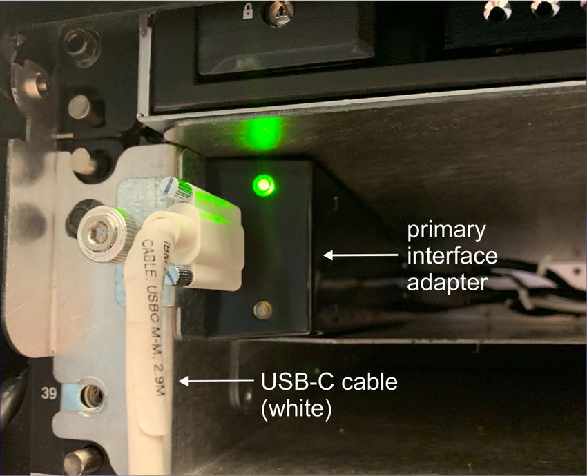
__ 9. If fastening the KMM to the front of the frame, plug the white USB-C cable into the primary
interface adapter as shown below. Then go to Step “11” on page 19.
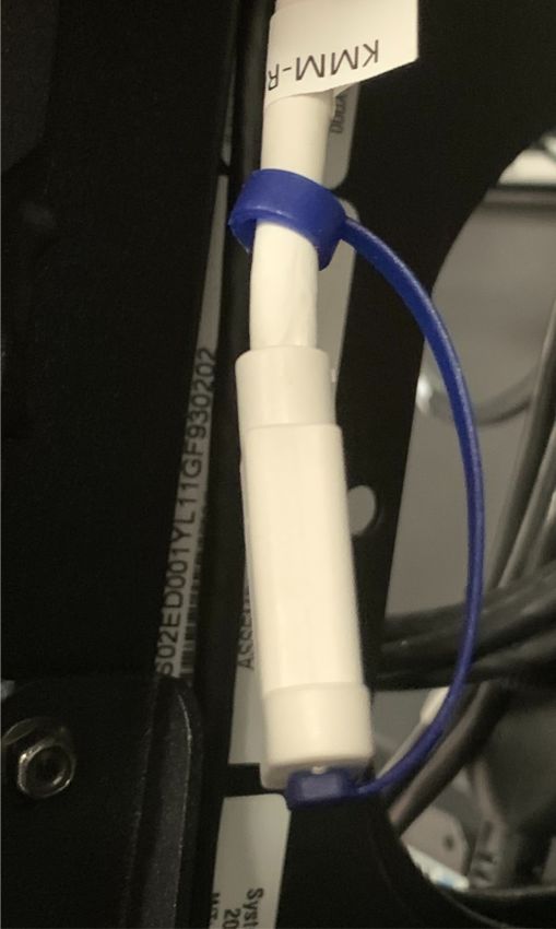
Chapter 1. Safety inspection 17__ 10. If fastening the KMM to the rear of the frame:
a. Remove the blue protective cap from the USB-C connector.
b. Plug the white USB-C cable into the connector.
18 IBM Z: 8562 Safety Inspection__ 11. Plug the other end of the white USB-C cable into the port on the compact KMM.
Chapter 1. Safety inspection 19Power on
__ 1. The green PSU PWR LED on the PSUs will turn on solid.
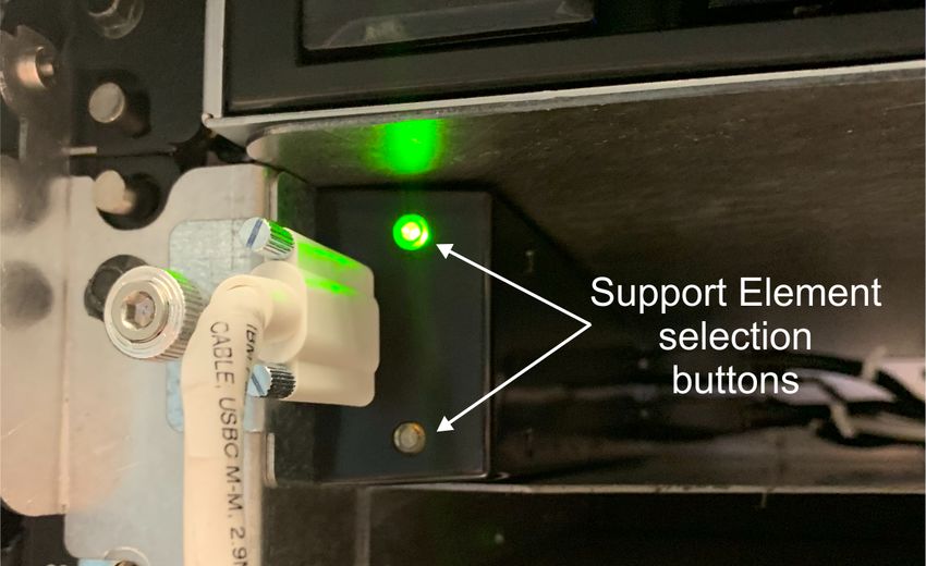
__ 2. Wait for the Primary Support Element Logon window to appear.
a. If the Alternate Support Element window appears, click the non-lit selection button on the
front end of the interface adapter to return to the Primary Support Element.
Note: The Support Element selection buttons light up when the related Support Element is
selected. This allows you to know which Support Element is communicating with the compact
KMM at any given time.
b. If the Hardware Management Appliance feature (FC 0100) is installed, the Hardware
Management Appliance HMC Logon window will appear.
1) Logon to Hardware Management Appliance HMC.
2) From the Tasks Index, click Virtual Support Element Management Task.
3) From this task, click Start SE Virtual Machine to start the Virtual Support Element.
4) Click Show SE Console. Wait for the Primary Support Element Logon window to appear.
5) If the Alternate Support Element window appears, click the top button on the KVM switch
to the other Hardware Management Appliance HMC. Then repeat Step 2b to start the
Primary Support Element.
__ 3. On the Primary Support Element Logon window:
• Type SERVICE in the Username field.
• Type SERVMODE in the Password field.
__ 4. Click System Management.
__ 5. Select the system name.
__ 6. Click Service.
__ 7. Click Service Status.
__ 8. If Service Status is already enabled, skip to Step “9” on page 20. Otherwise, complete the
following steps:
a. If required, select the check box.
b. Click Options.
c. Click Enable service status.
d. Click Save.
e. Click Yes.
f. Click OK, if applicable.
g. Click Cancel to close.
__ 9. Click Recovery.
__ 10. Click Power-On.
__ 11. Click OK to close the window when system power-on completes successfully.
20 IBM Z: 8562 Safety InspectionKapitel 1. Sicherheitsüberprüfung
Eine Sicherheitsüberprüfung wird ausgeführt:
• Wenn Sie ein System aufgrund eines IBM® Wartungsvertrags überprüfen
• Wenn es Gründe gibt, die Sicherheit der Einheit in Frage zu stellen
• Wenn der IBM Service telefonisch angefordert wird und bisher von IBM kein Service durchgeführt wur-
de
• Wenn eine Überprüfung der Änderungen und Anschlüsse durchgeführt wird.
Wenn die Überprüfung eine inakzeptable Sicherheitsbedingung ergibt, muss die Bedingung korrigiert wer-
den, bevor IBM Service für die Maschine bereitstellt.
Anmerkung: Die Behebung von Sicherheitsrisiken obliegt der Zuständigkeit des Eigners der Hardware.
Während der Durchführung dieser Überprüfung muss den folgenden Bereichen besondere Aufmerk-
samkeit geschenkt werden:
• Komponenten- bzw. Modelländerungen und Upgrades durch technische Änderungen
• Hinzufügungen von Verbrauchsmaterial, Logikschaltkarten oder Anschlüssen anderer Anbieter
• Fehlende Sicherheitsabdeckungen
• Entfernte, verblasste oder über übermalte Sicherheitsaufkleber
• Austauschanforderungen für Teile mit Primärstromversorgung
• Weitere Punkte, die die Produktsicherheit betreffen
Bevor Sie beginnen, müssen Sie den Kurs für allgemeine Sicherheit (General Safety) oder einen gleich-
wertigen Kurs für dieses Jahr absolviert haben. Überprüfen Sie die Veröffentlichung Elektrische Sicherheit
für IBM Servicemitarbeiter (IBM Form S229-8124) oder ein vergleichbares Handbuch. In manchen Regio-
nen gelten andere Anforderungen an Sicherheitsschulungen; weitere Informationen hierzu finden Sie im
Abschnitt für die Anforderungen an Sicherheitsschulungen für Ihre Region.
Benötigte Teile
• Ein IBM CE-Werkzeugsatz oder vergleichbare
• Kopien der sicherheitstechnischen Änderungen (Safety Engineering Changes) für diesen Maschinentyp
• Das neueste Maschinenprotokoll (sofern verfügbar)
• Das Handbuch Elektrische Sicherheit für IBM Servicemitarbeiter, IBM Form S229-8124
• Ein Fluke Digitalvoltmeter 8060A (IBM Teilenummer 8496278) oder vergleichbare
• Isolierband oder Gummihandschuhe
• Ein Suretest-Tester (IBM Teilenummer 25F9715) und ein isolierter Erdungsadapter (IBM Teilenummer
00P7019), bevorzugt in den Vereinigte Staaten (sofern verfügbar)
© Copyright IBM Corp. 2020 DEU-1Sicherheitsüberprüfung des Prozessors
Die Sicherheitsüberprüfung wird für alle Netzkabel ausgeführt.
Achtung: Lesen Sie die folgenden Hinweise, bevor Sie beginnen:
DANGER: Overloading a branch circuit is potentially a fire hazard and a shock hazard under
certain conditions. To avoid these hazards, ensure that your system electrical requirements do not
exceed branch circuit protection requirements. Refer to the information that is provided with your
device or the power rating label for electrical specifications. (D002)
DANGER: If the receptacle has a metal shell, do not touch the shell until you have completed the
voltage and grounding checks. Improper wiring or grounding could place dangerous voltage on the
metal shell. If any of the conditions are not as described, STOP. Ensure the improper voltage or
impedance conditions are corrected before proceeding. (D003)
DANGER: An electrical outlet that is not correctly wired could place hazardous voltage on the
metal parts of the system or the devices that attach to the system. It is the responsibility of the
customer to ensure that the outlet is correctly wired and grounded to prevent an electrical shock.
(D004)
DANGER: Heavy equipment — personal injury or equipment damage might result if mishandled.
(D006)
CAUTION: Only trained service personnel may replace this battery. The battery contains lithium.
To avoid possible explosion, do not burn or charge the battery.
Do not: Throw or immerse into water, heat to more than 100°C (212°F), repair or disassemble. (C002)
CAUTION: The doors and covers to the product are to be closed at all times except for service by
trained service personnel. All covers must be replaced and doors locked at the conclusion of the
service operation. (C013)
CAUTION: Ensure the building power circuit breakers are turned off BEFORE you connect the
power cord or cords to the building power. (C023)
67:!"#$%&,'()*+,-./0123)4567。9:;?@AB5)C
DEF/+G'()*@H5DE。>IJKLMN5OPQ)RSTUV,WXY)Z[\。(D002)
MN:!"#$%&'(,*+,-./0123456789:;?@(。BCD56EFG<
HI&'@(JKLMNO23。!"PLQRSTUOVW,XYZ[\。]^_`aEbFO23D
cdeW9:,fghij。(D003)
01:!"#$%&'()*+,,-./012#3456789:';782?@AB。DE
QR FG+H%&2I(*+JK'L,MNOP#。(D004)
67:!"#$—%&'()*+,-./012#$34。(D006)
9::!"#$%&'()*+,-.&'78,,-./&'012345。(C023)
Gefahr: Bei Überlastung eines Netzstromkreises besteht unter gewissen Umständen Brandgefahr
oder das Risiko eines elektrischen Schlags. Um dies zu vermeiden, stellen Sie sicher, dass der
elektrische Bedarf Ihres Systems die Absicherung des Netzstromkreises nicht überschreitet.
Technische Daten zur Elektrik stehen in der Dokumentation zu der IBM Einheit oder auf dem
Typenschild. (D002)
DEU-2 IBM Z: 8562 - SicherheitsprüfungGefahr: Besitzt die Netzsteckdose ein Metallgehäuse, die Steckdose nicht berühren, bevor die
Prüfung der Netzspannung und der Erdung erfolgreich durchgeführt wurde. Durch eine nicht
ordnungsgemäß angeschlossene Steckdose oder durch nicht ordnungsgemäße Erdung können
am Metallgehäuse gefährliche Berührungsspannungen auftreten. Ist die Prüfung nicht
erfolgreich, die Arbeit ABBRECHEN. Die korrekte Netzspannung und Impedanz herstellen,
bevor die Installation fortgesetzt wird. (D003)
Gefahr: Bei nicht ordnungsgemäß angeschlossener Netzsteckdose können an Metallteilen des
Systems oder an angeschlossenen Einheiten gefährliche Berührungsspannungen auftreten.
Für den ordnungsgemäßen Zustand der Steckdose ist der Betreiber verantwortlich. (D004)
Gefahr: Schwere Einheit — Gefahr von Verletzungen oder Beschädigung der Einheit
bei unsachgemäßer Behandlung. (D006)
Vorsicht: Die Türen und Abdeckungen müssen immer geschlossen sein. Sie dürfen nur von
ausgebildetem Kundendienstpersonal geöffnet werden. Nach Abschluss der Wartung müssen
wieder alle Abdeckungen eingesetzt und alle Türen geschlossen werden. (C013)
Vorsicht: Die Sicherungsautomaten der Gebäudeinstallation VOR dem Anschließen der
Netzkabel an die Stromversorgung des Gebäudes auftrennen. (C023)
Kapitel 1. Sicherheitsüberprüfung DEU-3You can also read