Lunar enCORE GE Healthcare
←
→
Page content transcription
If your browser does not render page correctly, please read the page content below
GE Healthcare

Lunar enCORE
Safety and Specification Manual
Rev 3 - Part number: LU43618EN
5/2009

GE Medical Systems LUNAR Contact Numbers
  Headquarters                                                                   Germany
  GE Medical Systems Lunar                                                       Beethoven Str. 239
  3030 Ohmeda Dr.                         GE Medical Systems IT GmbH             D-42655 Solingen
  Madison, WI 53718                       Munzinger Strasse 3-5                  Germany
  USA                                     D-79111 Freiburg, Germany              +49-212-2802-0
  +1 (800) 437-1171                       +49 212 2802 652                       +49-212-2802-390 (fax)
                                          +49 0761 45 43 233 (fax)
  China                                   France                                 Asia/Pacific
  No. 19 Changjiang Road                  11 Avenue Morane Saulnier              4-7-127 Asahigaoka
  Wuxi, Jiangsu, 214028                   78 457 VELIZY                          Hino-shi, Tokyo 191-8503
  P.R.C.                                  +33-1-34-49-5365                       Japan
  +86-510-85225888                        +33-1-34-49-5406 (fax)                 +81-42-585-5111
  +86-510-85226688 (fax)                                                         +81-42-585-3077 (fax)
 www.gehealthcare.com

                   YZB/USA 2099
 DPX Series        SFDA(I) 20023301115
                   YZB/USA 0509
 Prodigy Series    SFDA(I) 20043301375
                   YZB/USA 1104-2007
 iDXA              SFDA(I) 20073302084

GE Medical Systems LUNAR recommends viewing the instructions for navigating the Lunar iDXA, PRODIGY™, PRODIGY™ Advance,
PRODIGY™ Primo, PRODIGY™ Pro, DPX™ NT/Pro/MD+/Duo/Bravo™ Safety Information and Technical Specifications before pro-
ceeding through the online guide for the first time.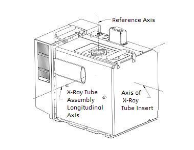
Table of Contents
   Introduction                                                  3
   Search                                                        3
   License and Warranty Information                              4
   General Product Information                                   5
   Training Information                                          5
   Cautions for DEXA Determinations                              6
   Precautions for Standard Operating Procedures                 6
   Patents                                                       7
   Standard Operating Procedures                                 7
   Scanner Table Assembly                                        7
   System Safety                                                 8
   Operator Safety                                               8
   Patient Safety                                                9
   Mechanical Safety                                            14
   External Symbols                                             14
   Internal Symbols                                             15
   Labels                                                       15
   Emergency Stop Button and Failsafe Circuit                   19
   Registration                                                 20
   Facilities                                                   20
   Electrical Safety                                            20
   Scatter Radiation                                            23
   System Maintenance                                           30
   Archive Image Files                                          30
   Test Emergency Stop Button                                   31
   Preventive Maintenance                                       31
   Dispose of Materials                                         32
   Space Requirements                                           32
   Component Specifications                                     34
   Functional Specifications                                    35
   Environmental Specifications                                 36
   Power Specifications                                         37
   X-Ray Generator Specifications                               38
   GE MEDICAL SYSTEMS X-Ray Tube Head Assembly                  44
   Compatible Components                                        51
   FDA Certified Components                                     52
   Index                                                        55

                                                   - 2 of 57-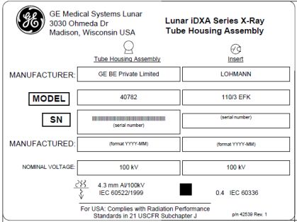
Introduction
This manual contains safety and maintenance information, and technical specifications, for your bone densitometer.

This manual should be used with the Lunar enCORETM Online Help you received with your system.

The information in this manual is subject to change without notice. You may use or copy the software described in this manual
only in accordance with the terms of your software license, product warranty, or service contract agreements.

No part of this publication may be reproduced for any purpose whatsoever, stored in a retrieval system, or transmitted in any
form or by any means, mechanical, photocopying, recording or otherwise, without the express written permission of GE Medical
Systems Lunar.

Any reproduction, photocopying and recording in whole or part is prohibited. Any information contained herein shall not be dis-
closed to any company viewed as a competitor to GE Medical Systems Lunar.

GE Medical Systems Lunar makes no warranty of any kind with regard to this material, and shall not be held liable for errors con-
tained herein or for incidental or consequential damages in connection with the furnishings or use of this manual.

The information contained in the manual is confidential and proprietary to GE Medical Systems Lunar. This information is provided
only to authorized representatives of GE Medical Systems Lunar's customers solely for the purpose of facilitating the use of GE Med-
ical Systems Lunar's products. No information contained herein may be disclosed to any unauthorized person for any purpose
whatsoever without prior written consent of GE Medical Systems Lunar.

Read the User and the Safety and Specification manuals thoroughly before using the system or attempting to service any com-
ponents. Unauthorized service may void system warranties or service contracts. Consult the GE Medical Systems Lunar Customer
Service Department before attempting any service: 800-437-1171 (U.S.A).

Lunar is a registered trademark of GE Medical Systems Lunar. All other product and brand names are registered trademarks or
trademarks of their respective companies.

Copyright© 1999, 2000, 2001, 2002, 2003, 2004, 2005, 2006, 2007, 2008, 2009

GE Medical Systems Lunar, Madison, Wisconsin. All rights reserved.

Search
You can search for topics and content within the online help.

     1. Click the Search tab in the online help window.

     2. Type the content for which you are searching.

                                                                - 3 of 57-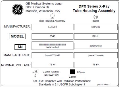
3. Click List Topics.
     4. Click any displayed topic name to display the desired topic.

License and Warranty Information
Please carefully read the following terms and conditions before installing or operating the GE Medical Systems Lunar Software
("Software"). By installing or using the Software in your GE Medical Systems Lunar product, You indicate your acceptance of these
terms and conditions. If You do not agree with the terms and conditions, do not install or operate the Software and return it to GE
Medical Systems Lunar.

The Software has been provided to You for use on a specific GE Medical Systems Lunar product. The Software is provided under
the terms of this Agreement and is licensed to You, not sold. Your rights to use the Software are subject to the terms and conditions
contained within this License Agreement and GE Medical Systems Lunar reserves any rights not expressly granted to You. This
License is non-exclusive and a non-transferable license to use the GE Medical Systems Lunar Software. Re-distribution of Software
or any documentation provided to you by GE Medical Systems Lunar is strictly prohibited.

This product includes some software components that are licensed under the GNU General Public License (GPL). Source code for
GPL components is available upon request.

The terms and conditions of this License Agreement and Limited Software Warranty are as follows:

1. LICENSE. This License allows You to:
(a) use the Software on a product in accordance with the accompanying documentation. To "use" the Software means that the
Software is either loaded in the temporary memory of a computer or installed on any permanent memory or media of a computer
(e.g., hard disk, CD-ROM, optical disk, zip disk, and the like);
(b) make one (1) copy, in machine-readable form, of the Software as provided to You solely for the purposes of backup; provided
that such copy includes the reproduction of any copyright notice or other proprietary notice appearing in or on such Software.

2. LICENSE RESTRICTIONS.
(a) YOU MAY NOT, EXCEPT AS EXPRESSLY PROVIDED FOR IN THIS LICENSE: (i) DECOMPILE, DISASSEMBLE, OR REVERSE ENGINEER THE
SOFTWARE (except to the extent applicable laws specifically prohibit such restriction); (ii) COPY, MODIFY, ADAPT, TRANSFER, TRANS-
LATE, RENT, LEASE, GRANT A SECURITY INTEREST IN, OR LOAN THE SOFTWARE OR ANY PORTION THEREOF; (iii) CREATE DERIVATIVE
WORKS BASED UPON THE SOFTWARE OR ANY PORTION THEREOF; OR (iv) REMOVE ANY COPYRIGHT OR PROPRIETARY NOTICES OR
LABELS IN OR ON THE SOFTWARE.
(b) You understand that GE Medical Systems Lunar may update or revise the Software, and in so doing incur no obligation to fur-
nish such updates to You under this License. GE Medical Systems Lunar has no obligation to improve, update or support the Soft-
ware in the future.
(c) In the event the instrument or product designated for the Software is sold or otherwise transferred to a third party, that party is
not authorized to use the Software unless they first pay to GE Medical Systems Lunar the applicable license fee and agree to the
terms and conditions of a Software License Agreement. Upon transfer of the Software or any copy thereof, the License granted
hereunder shall terminate immediately.

3. TERM AND TERMINATION.
This License is effective until terminated. This License will terminate immediately without notice from GE Medical Systems Lunar or
judicial resolution if You fail to comply with any provision of the License. Upon any termination of this License, You agree to return
or destroy the Software, all accompanying written materials and all copies thereof in any form. Section 5 will survive any ter-
mination.

4. EXPORT LAW.
You agree that neither the Software nor any direct product thereof is being or will be shipped, transferred or re-exported, directly
or indirectly into any country prohibited under United States law or regulations promulgated thereunder.

5. WARRANTY.
GE Medical Systems Lunar warrants that, to the best of our knowledge, the software provided with this License will perform as
described in the product's operator's manual and the technical specification for this Software. This limited warranty is contingent
upon proper use of the Software and does not cover any Software which has been modified, subjected to malicious logic, unusual
physical or electrical stress, or used on computer equipment not specified by GE Medical Systems Lunar.

GE Medical Systems Lunar does not warrant that the functions contained in this Software will meet your requirements, or that the
operation of the Software will be uninterrupted or error- free. Statements made about this Software do not constitute warranties

                                                               - 4 of 57-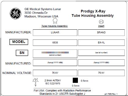
and shall not be relied upon by You in deciding whether to purchase the GE Medical Systems Lunar product or use the Software. IN
NO EVENT SHALL GE MEDICAL SYSTEMS LUNAR BE LIABLE TO YOU FOR ANY DAMAGES ARISING OUT OF THE USE OR INABILITY TO USE
SUCH SOFTWARE.

THE SOLE AND EXCLUSIVE REMEDY IN THE EVENT OF DEFECT IS EXPRESSLY LIMITED TO THE REPLACEMENT OF THE SOFTWARE PRO-
VIDED. IF FAILURE OF THE SOFTWARE HAS RESULTED FROM ACCIDENT OR ABUSE, GE MEDICAL SYSTEMS LUNAR SHALL HAVE NO
RESPONSIBILITY TO REPLACE THE SOFTWARE.

GE Medical Systems Lunar will consider this warranty to be void if You fail to comply with the terms in the Software License Agree-
ment.

6. TITLE.
Title, ownership rights, and intellectual property rights in the Software shall remain with GE Medical Systems Lunar. This Software is
protected by the copyright laws and treaties.

7. MISCELLANEOUS.
This Agreement represents the complete agreement concerning this License and may be amended only by a writing executed by
both parties. The License is governed by the laws of the State of Wisconsin, U.S.A. without regard to its conflict of laws principles. If
any provision of this Agreement is held by a court of competent jurisdiction to be unenforceable, that provision shall be enforced to
the maximum extent permissible and/or reformed only to the extent necessary to make it enforceable, and the remaining pro-
visions of this Agreement will not be affected or impaired in any way. If any legal action or proceeding is brought for the enforce-
ment of this Agreement, or because of any alleged dispute, breach, default or misrepresentation in connection with any of the
provisions of this Agreement, the successful or prevailing party shall be entitled to recover reasonable attorneys' fees and other
costs incurred in such action or proceeding, in addition to any other relief to which such party may be entitled.

General Product Information
The bone densitometer is designed to estimate the bone mineral density and body composition (lean and fat tissue mass) of
patients when medically indicated by their physicians. The manuals provide instructions for operating the software and scan
table, system information, and maintenance information.

Variables Affecting Scan Results

Scan results can be affected by operator technique and patient variability:

     1. Operator technique refers to patient positioning and scan analysis. To minimize technique variables, 1) establish con-
        sistent positioning and scan analysis routines by using anatomical landmarks when positioning patients, and 2) during
        analysis, manipulate raw scan data only when absolutely necessary.

     2. Patient variability refers to changes in the patient's medical history, metabolism, and diet. It also refers to diagnostic pro-
        cedures that involve radionuclide uptake and medical treatment, and the presence of external radiation (particularly the
        use of other radiation-generating devices in the vicinity of the system). To minimize patient variability, 1) thoroughly famil-
        iarize yourself with the patient's history, and 2) install the scanner in an environment effectively shielded from other
        sources of external radiation.

CAUTION: United States Federal Law restricts this device to the sale, distribution, and use by or on the order of a phy-
sician (USA only).

Training Information
GE Medical Systems Lunar or authorized GE Medical Systems Lunar distributors provide individual, hands-on training as part of
the installation procedure for your system. (GE Medical Systems Lunar distributors provide training for systems installed outside
the United States.) An Applications Specialist provides information on software and hardware operations, and reviews the warn-
ings and cautions in the manuals.

                IMPORTANT: Only trained technologists should operate the system. New technologists should receive
                training prior to unsupervised operation of the system. Additional training sessions are available on
                request for a nominal fee. For more information, contact the GE Medical Systems Lunar Customer Serv-
                ice Department at 800-334-5831, or your local GE representative.

                                                               - 5 of 57-
Cautions for DEXA Determinations
You should be aware of the following factors which may affect the clinical accuracy of DEXA spine estimates: marked distortions of
skeletal architecture-e.g., osteophytes, degenerative disc disease, spinal arthritis, spondylolisthesis, kyphoscoliosis, and vertebral
fractures-and significant calcium deposits in the aorta can falsely elevate spine bone mineral values. Regions that contain these
dystrophic calcifications can be excluded from the scan analysis in some cases. The scanner can be used to monitor changes in
bone mineral over time in patients with these disorders, but caution must be taken in interpretation. Use DEXA estimates as an aid
to other methods in the evaluation of patient bone mineral status in the clinical setting.

In addition, spine estimates will be difficult to interpret for patients with orthopedic metal devices and previous surgical inter-
ventions, such as bone grafts. Radiographic contrast material and radiopharmaceuticals used for myelograms, barium enemas,
and other diagnostic tests prevent accurate estimates. Barium clears the body within a few days, but the oil-based dyes used in
myelograms several years ago may remain within the body for years. A three-day waiting period is sufficient time for barium and
most radiopharmaceuticals to be completely discharged from the body.

Femur estimates will be difficult to interpret for patients with orthopedic metal devices and previous surgical interventions. The
most common complicating factors for femur estimates are prosthetic devices and surgical implants in the region of the bone
scan. Results may be adversely affected if the patient has difficulty with the desired 25° inward rotation of the leg or with main-
taining this position without movement.

Total Body estimates require consistent patient positioning for accurate results and will be difficult to interpret for patients with
orthopedic metal devices and previous surgical interventions. The operator should pay particular attention to the location of the
patient's arms, keeping the positioning the same for each scan. Results may be affected if the patient moves during the scan.

Precautions for Standard Operating Procedures
     1. Do not attempt to operate the scanner without first reading this manual.

     2. Do not remove the assembly panels or attempt any repairs without prior instructions from authorized GE Medical Sys-
        tems Lunar personnel.

     3. Perform the Quality Assurance procedure each morning. If any test fails, check the position of the calibration block and
        rerun the QA procedure. If a test fails again, contact GE Medical Systems Lunar Support. Also, call GE Medical Systems
        Lunar if more than two failures occur in a one-week period. If the room temperature changes more the 5°C during the
        day, then perform another Daily QA.

     4. If the patient is or might be pregnant, always contact the patient's physician before performing a scan.

     5. Remain in the room with the patient while a scan is in progress. Assure the patient does not move during the meas-
        urement. Minimize the amount of time the patient lies flat on the scan table.

     6. Restrict access to the room to authorized personnel.

     7. Do not attempt to service any of the system's electrical components while the scan table is turned ON. High voltage is
        used to produce x-rays.

     8. Radiation safety information is located within this manual you received with your system. Review this information before
        operation.

     9. To stop the scanner in an emergency, press the emergency stop button on the scan arm. DO NOT use the emergency
        stop button to routinely abort a scan.

   10. Remove any fluids which are spilled on pad or any surface of table immediately.

   11. All surfaces should be cleaned to meet site's guidelines for handling blood and body fluids. Pad material may be dam-
       aged by certain chemicals Use appropriate hospital grade disinfectant followed by mild detergent.

   12. Do not generate x-rays through the use of remote applications.

                                                              - 6 of 57-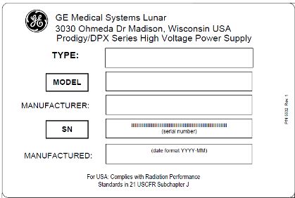
13. Protect the computer against malicious logic and unauthorized network access. Only allow authorized user access. Pre-
       vent virus attacks through the use of firewalls, anti-virus software and software patch updates. Contact your local GE rep-
       resentative for more information.

   14. DPX Duo: Extend the step the full distance to provide maximum surface area for the patient to get on and off the table
       without risk of injury.

   15. DPX Duo: Do not place an excessive load on foot rest (stirrup), drawers, or leg extension.

   16. DPX Duo: Do not sit on leg extension table.

Patents
This product is covered by the claims of one or more of the following patents:

U.S. patents #5,040,546, #5,306,306, #5,480,439, #5,533,084, #6,038,281, #6,081,582, #U520050249331A1,
#U520050247882A1, #U520050247880A1

Standard Operating Procedures
     1. Quality Assurance: Every morning, before you start patient measurements, complete the daily Quality Assurance pro-
        cedure. Refer to chapter 2 of the enCORE Operator's Manual. Make sure you save your printed results for future reference.

     2. Measure Patients: If time allows, enter the Primary, Secondary, and Additional data for the patients you expect to meas-
        ure during the day. Refer to chapter 3 of the enCORE Operator's Manual to measure a patient.

     3. Analyze Results: Analyze and print results immediately after each patient measurement if time allows. Otherwise,
        analyze all of the patient files after the last patient has been measured. Refer to chapter 4 of the enCORE Operator's Man-
        ual to analyze results.

     4. Archive image files: Archive your image files before you leave for the day. In the unlikely event of a computer mal-
        function, it is very important that you have archived files of all of your patient measurements to rebuild your database.
        Refer to Archive image files on page 30 for archive procedures.

     5. Shut down computer: At the end of the day, select Exit from the Main screen, select Shut Down from the Close window,
        and click OK to close the program.

         Note: Do not turn off the scanner at the end of the day for stationary systems.

Scanner Table Assembly
Note: Do not attempt to service the scanner table assembly. Please call GE MEDICAL SYSTEMS Lunar Support or your GE MEDICAL
SYSTEMS Lunar distributor.

Scanner table
The scanner table is used to support the patient during a measurement or general examination (DPX Duo). In addition, the x-ray
source assembly and other electronics are contained inside the scanner table.

Scanner arm
The laser light, emitted from an aperture on the scanner arm, helps you locate the measurement start position. Positioning
switches let you move the scanner arm until the laser light is located at the correct start position. The start position is different for
each measurement type.

The DPX Duo and DPX Bravo scanner arm has a release and locking mechanism allowing the upper arm to swivel when the
scanner is idle. The scanner arm must be in the locked position over the scanner table to perform a measurement.

                                                                - 7 of 57-
Display panel
The following describes the indicators located on the scanner arm display panel:
Indicator Status (on)
Green (power) Power is supplied to the scanner table.
Yellow (x-ray) X-ray tube assembly is supplying x-rays.
Yellow (shutter) Shutter is open.
Amber (laser) Laser is on.
Emergency stop button
Push the red emergency stop button to stop the scanner arm and immediately shut down x-rays in an emergency. Do not use the
emergency stop button to routinely stop the scanner during normal operation.
Positioning switches
The positioning switches move the scanner arm and detector to the measurement start position (the laser light indicates the posi-
tion of the detector). The Back/Front switch moves the detector across the width of the scanner table. The Left/Right switch moves
the scanner arm down the length of the scanner table.
Swing arm position sensing switches (DPX Duo, DPX Bravo)
The swing arm position sensing switches detect the locking status of the swing arm and the swing arm latch. The swing arm latch
must be locked and the swing arm must be in the locked position over the scan table before a measurement can be performed.
Release of the swing arm latch during a measurement will abort the scan and the measurement data will be lost.
iDXA Start Scan button
The start scan button initiates the patient measurement. The start scan button is located on the display panel near the positioning
switches.
System Safety
Obey these safety guidelines at all times:
● Read the manual before you operate the scanner.
● The technologist operating the scanner must remain in the room with the patient during the measurement.
● Do not attempt to service the scanner. Please call GE MEDICAL SYSTEMS Lunar Support or your GE MEDICAL SYSTEMS
Lunar Distributor.
● When the scanner is not in use, make sure the Shutter Open, X-ray, and Laser lights are off.
● Do not put excessive pressure on the scanner arm.
● Use the scanner table for patient measurements and examinations (DPX Duo) only: do not sit, stand or lie on the table for
other purposes.
● Do not let liquids touch the computer or scanner table mechanics and electronics.
Operator Safety
Personnel monitors
Personnel monitors are not necessary to operate the scanner.
It is not likely that you can receive more than 25% of the maximum permissible x-ray dose from the scanner. However, some facil-
ities choose to use personnel monitors. Refer to your city, county or state Health Department or Radiation Safety Officer for your
facility's policy.
Film badges and thermal luminescent dosimeter (TLD) badges are obtained from a supplier accredited by the National Voluntary
Laboratory Accreditation Program for personnel dosimetry processing.
The following is a sample situation for a clinic measuring an AP spine and Dual Femur on 5 subjects per day with an exposure rate
of 0.18mR/hr at a distance of 2 meters estimated from the iDXA isodose curves.
- 8 of 57-Sample Calculation for Estimated Exposure per Year from Scatter with iDXA Densitometer
Equivalent 2.5 mA
Scan Type Mode Average Scans/Day Scan Time/Day Scan Time/day
(sec/day) (sec/day)
AP Spine Standard 5 260 260
Dual Femur Standard 5 535 535
2.5 mA Scan Time per Day (sec) 795
2.5 mA Scan Time per Day (hours) 0.221
2.5 mA Scan Time per Week (hours) 1.11
2.5 mA Scan Time per Year (hours) 57.5
2.5 mA Exposure from Isodose Plots (mR/hr) 0.18
Total Exposure for 1 Year (mR) 10.3
Total Absorbed Dose for 1 Year (mRad) 0.92 Rad/R 9.5
X-ray and shutter graphics
During a measurement or Quality Assurance procedure, x-ray and shutter graphics are shown on the computer monitor. The
graphics are green to indicate x-rays are off and the shutter is closed, and yellow to indicate x-rays are on and the shutter is open.
X-rays off and shutter closed (green):
X-rays on and shutter open (yellow):
X-ray shutter
When power to the scanner is interrupted during a measurement or Quality Assurance procedure, the shutter closes and the x-
ray tube stops generating x-radiation.
X-ray power supply
The x-ray tube assembly uses high voltage to generate x-rays. DO NOT touch internal components. DO NOT attempt to service
internal components.
Patient Safety
Pinch points
The Warning label identifies the location of possible pinch points.
When the scanner arm is in motion, make sure possible pinch point areas are clear at all times. Patient limbs must remain inside
the boundaries of the table top. A pinch point is possible between the scanner arm and table.
- 9 of 57-Laser Safety
DO NOT STARE INTO THE LASER BEAM during patient positioning and Quality Assurance procedures. The label that follows is
located on the scanner arm and shows the location of the laser aperture.
Radiation Safety
X-ray exposure: The system makes radiation when electric voltage is supplied to, and current flows through, the x-ray tube. Dur-
ing a measurement, the shutter opens to let a beam of radiation pass through the scanner table and patient. The nominal radi-
ation field at the iDXA scanner table top is 18.4 mm x 3.3 mm, at the Prodigy table top is 19.5 mm x 3.4 mm and at the DPX series
table top it is 2 mm. Lead oxide shielding surrounds the x-ray tube insert inside the tube housing assembly and reduces radiation
levels around the scanner table.
Skin entrance dose: A Victoreen model 530 Precision Electrometer/ Dosemeter with a Model 660-5 Ion Chamber was used to
measure the X-ray entrance dose. Refer to the "Current and Typical Dose Tables" for irradiation times and skin entrance doses.
Measurement modes
Patient thickness determines the appropriate measurement mode. The program selects the appropriate mode based on the
patient's height and weight.
Lunar enCORE Systems
iDXA, PRODIGY, PRODIGY Advance DPX Series
Mode Patient thickness Patient thickness
Thick >25 cm >25 cm
Standard 13-25 cm 15-25 cm
ThinForearm Standard 0.188 14.2 x 10.0 24 10
Hand Standard 0.188 25.3 x 18.0 69 10
Total Body Thick 0.188 196.8 x 66 796 6
Total Body Standard 0.188 196.8 x 66 436 3
Total Body Thin 0.188 196.8 x 66 436 3
LVAH Standard 2.500 42.7 x 20.0 271 329
LVAH Thin 0.625 60.0 x 20.0 381 82
Lateral Spine Standard 2.500 19.0 x 18.0 104 329
Orthopedic
Femur Thick 2.500 23.7 x 15.0 109 329
Orthopedic
Femur Standard 2.500 23.7 x 15.0 53 146
Orthopedic
Femur Thin 0.625 23.7 x 15.0 53 37
Small Animal Standard 0.188 75.8 x 25.0 264 10
A All modes are 100kV, ±1kV.
B Tube current is ±1% at the maximum current.
C Imaging time measured from shutter open to shutter close, 90% to 100% of indicated value.
D Sizes of measurement areas and irradiation times will be less than those listed above if you use the SmartScan feature.
E Measurement lengths and times are dependent on patient height and product version.
F Dose measurements are constrained by Daily QA limits.
G Irradiation times and dose values do not consider a “sweep retry” feature which can double the dose for a single transverse
sweep within an entire scan. If a retry occurs a slight increase in irradiation time and skin entrance dose would be expected. The
retry feature reduces need to rescan entire patient.
H The activation of the spine geometry application permits a maximum scan length up to 69.5 cm.
Current and typical dose information for Lunar PRODIGY, PRODIGY Advance, PRODIGY Pro modes
Estimated
Typical Meas- Skin
urement Area Irradiation Entrance
Current L x W cm x cm times Dose
Site Mode 1 (mA) 2 4,5 (sec) 3,4,5 (μGy) 6,7
AP Spine Thick 3.000 15.1 x 12.1 56 83
AP Spine Standard 3.000 15.1 x 12.1 28 37
AP Spine Thin 0.750 15.1 x 12.1 28 9
AP Spine QuickView 3.000 15.1 x 12.1 14 12
Femur Precise 3.000 15.1 x 12.1 56 83
Femur Thick 3.000 15.1 x 12.1 56 83
Femur Standard 3.000 15.1 x 12.1 28 37
Femur Thin 0.750 15.1 x 12.1 28 9
Femur QuickView 3.000 15.1 x 12.1 14 12
DualFemur Thick/Precise 3.000 2 x 15.1 x 12.1 112 83
DualFemur Standard 3.000 2 x 15.1 x 12.1 55 37
DualFemur Thin 0.750 2 x 15.1 x 12.1 55 9
DualFemur QuickView 3.000 2 x 15.1 x 12.1 28 12
- 11 of 57-Forearm Standard 0.150 13.4 x 10.0 21 2
Hand Standard 0.150 23.5 x 18.0 61 2
Total Body Thick 0.150 151.5 x 60 532 0.8
Total Body Standard 0.150 151.5 x 60 295 0.4
Total Body Thin 0.150 151.5 x 60 295 0.4
Lateral BMD Standard 3.000 15.1 x 12 56 83
LVA Standard 3.000 38.7 x 15.0 175 83
APVA Thick 3.000 38.7 x 15 85 37
APVA Standard 3.000 38.7 x 15 85 37
APVA Thin 0.750 38.7 x 15 85 9
Orthopedic Femur Thick 3.000 20.2 x 15 91 83
Orthopedic Femur Standard 3.000 20.2 x 15 44 37
Orthopedic Femur Thin 0.750 20.2 x 15 44 9
Small Animal Standard 0.15 75.7 x 25.0 261 1.8
Current and typical dose information for Lunar PRODIGY Primo modes
Estimated
Typical Meas- Skin
urement Area Irradiation Entrance
Current L x W cm x cm times Dose
Site Mode 1 (mA) 2 4,5 (sec) 3,4,5 (μGy) 6,7
AP Spine Thick 1.500 15.1 x 12.1 96 74
AP Spine Standard 1.500 15.1 x 12.1 56 42
AP Spine Thin 0.375 15.1 x 12.1 56 10
Femur Thick 1.500 15.1 x 12.1 96 74
Femur Standard 1.500 15.1 x 12.1 56 42
Femur Thin 0.375 15.1 x 12.1 56 10
DualFemur Thick 1.500 2 x 15.1 x 12.1 193 74
DualFemur Standard 1.500 2 x 15.1 x 12.1 112 42
DualFemur Thin 0.375 2 x 15.1 x 12.1 112 10
Forearm Standard 0.150 13.4 x 10.0 21 2
Total Body Thick 0.150 151.5 x 60 532 0.8
Total Body Standard 0.150 151.5 x 60 295 0.4
Total Body Thin 0.150 151.5 x 60 295 0.4
Lateral BMD Standard 3.000 15.1 x 12 56 83
LVA Standard 3.000 38.7 x 15.0 175 83
APVA Thick 3.000 38.7 x 15 85 37
- 12 of 57-APVA Standard 3.000 38.7 x 15 85 37
APVA Thin 0.750 38.7 x 15 85 9
Orthopedic
Femur Thick 3.000 20.2 x 15 91 83
Orthopedic
Femur Standard 3.000 20.2 x 15 44 37
Orthopedic
Femur Thin 0.750 20.2 x 15 44 9
Current and typical dose information for Lunar DPX-PRO/NT/Duo/Bravo modes
Estimated
Typical Meas- Skin
urement Area Irradiation Entrance
Current L x W cm x cm times Dose
Site Mode 1 (mA) 2 4,5 (sec) 3,4,5 (μGy) 6,7
AP Spine Thick 1.500 15.1 x 12.1 215 41
AP Spine Standard 1.500 15.1 x 12.1 108 20
AP Spine Thin 0.375 15.1 x 12.1 215 5
Not Avail-
AP Spine QuickView able
Femur Precise 1.500 14.0 x 12.0 221 41
Femur Thick 1.500 14.0 x 12.0 221 41
Femur Standard 1.500 14.0 x 12.0 132 20
Femur Thin 0.375 14.0 x 12.0 221 5
Not Avail-
Femur QuickView able
DualFemur Thick/Precise 1.500 2 x 14.0 x 12.0 443 41
DualFemur Standard 1.500 2 x 14.0 x 12.0 264 20
DualFemur Thin 0.375 2 x 14.0 x 12.0 443 5
Not Avail-
DualFemur QuickView able
Forearm Standard 0.050 11.5 x 10.0 286 3
Not Avail-
Hand Standard able
Total Body Thick 0.100 151.5 x 60 1337 0.3
Total Body Standard 0.100 151.5 x 60 670 0.2
Total Body Thin 0.100 151.5 x 60 900 0.2
Lateral BMD Standard 1.500 12.0 x 12.0 189 41
Not Avail-
LVA Standard able
Not Avail-
APVA Thick able
Not Avail-
APVA Standard able
- 13 of 57-Not Avail-
APVA Thin able
Orthopedic Femur Thick 1.500 20.1 x 15.0 385 41
Orthopedic Femur Standard 1.500 20.1 x 15.0 223 20
Orthopedic Femur Thin 0.375 20.1 x 15.0 385 5
Not Avail-
Small Animal Standard able
Current and typical dose information for DPX-MD+ modes. Note, Standard mode is replaced with
Standard-MD mode.
Estimated
Typical Meas- Skin
urement Area Irradiation Entrance
Current L x W cm x cm times Dose 6
Site Mode 1 (mA) 2 4,5 (sec) 3,4,5 (μGy)
AP Spine Standard-MD 0.750 15.0 x 12.0 212 20
Femur Standard-MD 0.750 15.0 x 12.0 236 20
Orthopedic Femur Standard-MD 0.750 15.0 x 12.0 336 20
1 All modes are 76kV, ±1kV.
2 Tube current is ±1% at the maximum current.
3 Imaging time measured from shutter open to shutter close, 90% to 100% of indicated value.
4 Sizes of measurement areas and irradiation times will be less than those listed above if you use the SmartScan feature.
5 Measurement lengths and times are dependent on patient height and product version.
6 Dose measurements are constrained by Daily QA limits. For example, the maximum spine (standard mode) range is 30 to 85μGy
for Prodigy densitometers and 8 to 28μGy for DPX series densitometers.
7 Irradiation times and dose values do not consider a “sweep retry” feature which can double the dose for a single transverse
sweep within an entire scan. If a retry occurs a slight increase in irradiation time and skin entrance dose would be expected. On
Lunar Prodigy scanners DF+12000 and above, all Prodigy Advance, and DPX+NT scanners running version 8 software and
newer, a sweep may be retried one time during acquisition. A maximum of two sweeps can be retried per scan. The retry feature
reduces need to rescan entire patient.
Mechanical Safety
The scanner arm moves down the entire length of the scanner table. Make sure the patient does not interfere with the movement
of the scanner arm to prevent possible injury. In addition, make sure that there are no objects behind the scanner table that might
obstruct movement of the scanner arm.
Weight applied to the Lunar iDXA must not exceed 204kg (450 pounds). Weight applied to the Lunar DPX-Pro/NT/MD+ scan table
bed must not exceed 136kg (300 pounds). Weight applied to the Lunar PRODIGY, PRODIGY Advance, PRODIGY Primo, DPX-
Duo/Bravo scan table bed or footstep (DPX Duo) must not exceed 159kg (350 pounds).
External Symbols
Attention: shows the Operator's Manual contains important safety information such as the location of pinch
points.
- 14 of 57-Emergency Stop Button: shows the location of the emergency stop button.
Laser On: shows the location of the Laser On indicator.
Shutter Open: shows the location of the Shutter Open indicator.
X-ray On: shows the location of the X-ray On indicator.
Type B Equipment: shows that the scanner has Type B protection against electrical shock.
Power On: shows the location of the Power On indicator and the switch position for Power On.
Power Off: shows the switch position for Power Off.
Internal Symbols
Protective Earth: shows the location of a Protective Earth terminal.
Functional Earth: shows the location of a Functional Earth terminal.
Labels
Laser Caution and Ion-
izing Radiation Label:
Shows that the scanner
uses a Class II laser. The
label includes the
required symbols and
precaution (Laser Radi-
ation: Do not stare into
beam. Class II Laser
Product).
- 15 of 57-Tube Head Assembly
"Lunar iDXA" Label:
This label gives tube
head assembly and x-
ray source char-
acteristics information. It
is located on the tube
head assembly and the
foot panel of the
scanner. The label
appearance may vary
from the one displayed
here. The Lunar iDXA
series label covers appro-
priate Tube Head
Assembly for Lunar iDXA
scanners.
Tube Head Assembly
“DPX Series” Label: This
label gives tube head
assembly and x-ray
source characteristics
information. It is located
on the tube head
assembly and the foot
panel of the scanner.
Tube Head Assembly
label covers DPX-NT,
DPX-MD+, DPX Bravo,
and DPX Duo.
- 16 of 57-Tube Head Assembly
“Prodigy Series” Label:
This label gives tube
head assembly and x-
ray source char-
acteristics information. It
is located on the tube
head assembly and the
foot panel of the
scanner. The label
appearance may vary
from the one displayed
here. The Prodigy series
label covers appropriate
Tube Head Assembly for
Prodigy and Prodigy
Advance scanners.
Inherent Filtration: Sym-
bol from EN60417-1,
5381
Tube Insert: Symbol
from EN60417-1, 5337
X-ray Source: Symbol
from EN60417-1, 5338
Focal Point: Symbol
from EN60417-1, 5327
System Label: This label
gives system input
power requirements and
compliance information.
It is located on the foot
panel of scanners. The
Attention symbol indi-
cates need to read
accompanying doc-
uments. Person symbol
refers to Type B applied
part for degree of electric
shock protection per
EN60601-1. The Fan
symbol denotes ionizing
radiation is generated.
The CE mark shows
compliance with the Med-
ical Device Directive
93/42/EEC. The ETL mark
shows compliance to UL
60601-1 and CAN/CSA
C22.2 No. 601 The
Waste Receptacle mark
indicates that the waste
of electrical and elec-
tronic equipment must
not be disposed as
- 17 of 57-unsorted municipal
waste and must be col-
lected separately. Please
contact an authorized
representative of the
manufacturer for infor-
mation concerning the
decommissioning of
your equipment.
High Voltage Power
Supply: This label gives
high voltage power
supply (x-ray generator)
information. It is located
on the high voltage
power supply and foot
panel of the scanner.
Prodigy/DPX series High
Voltage Power Supply
label covers all the latest
Lunar products since
they use the same HVPS
part number.
X-ray Controller: This
label shows x-ray con-
troller compliance. It is
located near the x-ray
controller and on the
foot panel of the
scanner. The Lunar iDXA
X-ray Controller
Assembly label covers all
the Lunar iDXA products.
Prodigy/DPX series X-
ray Controller Assembly
label covers all the latest
Lunar products. Labels
show model/serial
number for that specific
product.
Collimator Assembly:
This label gives col-
limator assembly infor-
mation. It is located on
the collimator and foot
panel of the scanner.
The Lunar iDXA Col-
limator Assembly label
covers all Lunar iDXA
products. Prodigy/DPX
series Collimator
Assembly label covers
latest Lunar products.
Labels show model/se-
- 18 of 57-rial number for that spe-
cific product.
Warning Label and
Radiation Symbol: The
Warning label shows
that the system uses ion-
izing radiation. It is
found only on systems
delivered in the United
States. Always obey
instructions for safe
operation.
Grounding Reliability
Label: This label states
that grounding reliability
can only be maintained
when using a "Hospital
Grade" or "Hospital Only"
receptacle. It is found on
all power cords of sys-
tems delivered in the
United States.
Emergency Stop Button and Failsafe Circuit
If the hardware malfunctions, the scanner has two safety features for operator and patient safety: an Emergency Stop button and
a Failsafe Circuit.
CAUTION: Be prepared to abort the scan in the unlikely event arm motion stops
with the x-rays on.
Emergency stop button
The emergency stop button is the round, red button located on the scanner display panel.
NOTE: When the Emergency Stop Button is pushed, data is not saved to the database. You must measure the patient
again.
1. Push the Emergency Stop button to stop a measurement in an emergency. Power to the scanner table motors, x-ray tube
head, shutter, and laser is turned off.
NOTE: Do not use the emergency stop button to routinely stop the scanner during normal operation.
2. Select OK in the message window on the computer screen.
NOTE: If there is a hardware problem, DO NOT try to measure a patient. Call GE Medical Systems Lunar Support or your
GE Medical Systems Lunar distributor.
Failsafe circuit
During a diagnostic failure, the Failsafe Circuit stops power to the scanner motors and closes the x-ray shutter. A message is
shown on the computer that describes the failure. Call GE Medical Systems Lunar Support or your GE Medical Systems Lunar dis-
tributor and provide the failure description.
- 19 of 57-Registration
Government health departments can require medical facilities to register diagnostic x-ray equipment. Many municipal and state
health agencies require medical health facilities to employ certified radiologic technologists to operate diagnostic x-ray devices.
Contact your local regulatory authorities or GE representative for registration guidelines and regulation compliance.
Facilities
Install a "Caution X-Radiation" sign in the area or room where the system is operated. Because of low leakage levels of radiation
from the x-ray tube assembly, additional shielding in the walls, floor, or ceiling is not necessary. However, call your state or local
health and radiation safety departments for shielding requirements.
Electrical Safety
WARNING: Insulate patient from any metal associated with the DPX Duo by using a
nonconductive material during cauterization or similar treatments to
avoid shock or burns.
Do not plug additional outlet strips or extension cords into power con-
nected to scanner.
IEC and UL/CSA certification
To maintain electrical safety, all computer equipment and accessories connected to the scanner must meet all requirements for
safety. U.S.A. and Canada require UL/CSA and FCC certification. European countries require CE mark certification. Other countries
should follow their local requirements for computer equipment and accessories certification. Declarations of conformity to the
required standards should meet or exceed the requirements of EN 60950, "Safety of Information Technology Equipment" and EN
55024 "Information Technology Equipment - Immunity Characteristics".
Electromagnetic interference
Although the scanner meets safety standards regarding electromagnetic interference (EN60601-1-2), you may still experience a
loss of performance under extreme electromagnetic conditions. Maximize the distance between the scanner and other equipment.
Use a dedicated power line to avoid interference to and from the scanner.
Electromagnetic Compatibility (EMC) Performance
All types of electronic equipment may characteristically cause electromagnetic interference with other equipment, either
transmitted through air or connecting cables. The term EMC (Electromagnetic Compatibility) indicates the capability of
equipment to curb electromagnetic influence from other equipment and at the same time not affect other equipment with
similar electromagnetic radiation from itself. Proper installation following the service manual is required in order to achieve the full
EMC performance of the product. In case of issues related to EMC, please call your service personnel.
- 20 of 57-Declarations of Immunity and Emissions - iDXA, Prodigy Series, DPX Series
Immunity Standard Test Input Frequency Test
Type Voltage Compliance
EMS IEC 61000-4-2 ESD 230 50 Hz +/- 6kV Contact, +/- 8kV Air
VAC Direct/Indirect-Contact +/-
2,4,6kV
Direct-Air +/-2,4,8kV
EMS IEC 61000-4-3 Radiated RF 230 50 Hz 3 V/ m 80 MHz to 2.5 GHz
VAC
EMS IEC 61000-4-4 EFT 230 50 Hz +/- 2kV PS Line,
VAC +/- 1kV I/O lines
EMS IEC 61000-4-4 EFT 100 60 Hz +/- 2kV PS Line,
VAC +/- 1kV I/O lines
EMS IEC 61000-4-5 Surge 230 50 Hz +/- 1kV Diff.Mode
VAC +/- 2kV CommonMode
EMS IEC 61000-4-5 Surge 100 60 Hz +/- 1kV Diff.Mode
VAC +/- 2kV Common Mode
EMS IEC 61000-4-6 Conducted 100 60 Hz 3 Vrms 150 KHz to 80MHz
RF VAC
EMS IEC 61000-4-8 Power 230 60 Hz 3A/m
Frequency, VAC
Magnetic
Field
EMS IEC 61000-4-8 Power 230 50 Hz 3A/m
Frequency, VAC
Magnetic
Field
EMS IEC 61000-4-11 Voltage Dip, 230 50 Hz < 5% Ut for 0.5 cycle
short inter- VAC 40 % Ut for 5 cycles
ruptions and 70% Ut for 25 cycles
voltage var-EMC Environment and Guidance
-Floors should be wood, concrete, or ceramic tile. If floors are covered with synthetic material, the relative humid-
ity should be at least 30%.
-A UPS (uninterruptable power supply) is required to pass 61000-4-11 test at the 100V level for iDXA.
-Mains power quality should be that of a typical commercial and/or hospital environment. If the user requires
continued operation during power mains interruptions, it is recommended that the system be powered through
a UPS.
-Separation distance to radio communication equipment must be maintained according to the method in the fol-
lowing table.
-NOTE: These guidelines may not apply in all situations. Electromagnetic propagation is affected by absorption
and reflection from structures, objects and people.
-The Lunar densitometer is suitable for use in all establishments, including domestic establishments and those
directly connected to the public low-voltage power supply network that supplies buildings used for domestic pur-
poses.
Recommended Separation Distance between portable and mobile RF communications
equipment and the Lunar densitometer
The Lunar iDXA is intended for use in an electromagnetic environment in which radiated RF disturbances are con-
trolled. The customer or the user of the Lunar iDXA can help prevent electromagnetic interference by maintaining
a minimum distance between portable and mobile RF communications equipment (transmitters) and the Lunar
densitometer as recommended below, according to the maximum output power of the communications equip-
ment.
Rated maximum Separation distance according to frequency of transmitter in meters
output power of
transmitter 150 kHz to 80 MHz 80 MHz to 800 MHz 800 MHz to 2.5 GHz
W
0.01 0.1 0.1 0.2
0.1 0.4 0.4 0.8
1.0 1.2 1.2 2.4
10 3.7 3.7 7.4
100 11.7 11.7 23.3
NOTE 1: At 80 MHz and 800 MHz, the separation distance for the higher frequency range applies.
NOTE 2: These guidelines may not apply in all situations. Electromagnetic propagation is affected by absorption
and reflection from structures, objects and people.
Peripheral configurations
WARNING: The correct connection of the computer and all peripherals is necessary
to maintain electrical safety. The signal cable of the scanner is intended
only for connection to an approved computer. Call GE Medical Systems
Lunar Support or your GE Medical Systems Lunar distributor before
adding peripherals.
Operator shall not touch patient and computer or peripherals simul-
taneously.
Standard room configuration
The computer, peripherals, and all other equipment must be located more than 1.5 m or 1.83 m (U.S.A and Canada) from the
scanner. Use an outlet strip to power the computer and all peripherals. The outlet strip must be mounted off the floor so that it
does not touch other equipment. If your outlet strip was provided by GE Medical Systems Lunar, it has a maximum output of 15A,
120VAC. Only system-related equipment should be powered by the outlet strip.
- 22 of 57-A modem and/or network connection can be made at any time if you are using the standard room configuration.
Small room configuration
You must power the computer, peripherals, and all other equipment with an isolating transformer if the room is too small to main-
tain at least 1.5 m or 1.83 m (U.S.A and Canada) of separation between the scanner and all other equipment.
The isolation transformer supplied by GE Medical Systems Lunar has a maximum output of 400/500VA. Only system-related equip-
ment should be powered by the isolation transformer. Failure to use an isolation transformer can cause leakage currents in
excess of 100 microamperes.
A modem and/or network connection can only be made in the small room configuration if all exposed metal surfaces of the com-
puter and peripherals are out of the patient environment.
Lunar PRODIGY system no. DF+11999 and lower
Scanner power output configuration: GE Medical Systems Lunar recommends that you use scanner power output to provide iso-
lated power to the computer and all peripherals. The power strip must be mounted off the floor such that it does not touch other
equipment. The computer and ALL peripherals must be powered by the scanner. All other equipment must not be powered by the
scanner and must be located more than 1.5 m or 1.83 m (U.S.A and Canada) from the scanner. Failure to use scanner power out-
put can cause leakage currents in excess of 100 microamperes.
If a network and/or modem connection is needed, refer to the wall outlet configuration.
Wall outlet configuration: As an option to scanner power output, a wall outlet can be used to power the computer and periph-
erals. Isolated power from the scanner must not be used to power any equipment if a wall outlet is used. All exposed metal sur-
faces of the computer, peripherals, and other equipment must be located more than 1.5 m or 1.83 m (U.S.A and Canada) from the
scanner.
A network and/or modem connection can be made to the computer if power is supplied from a wall outlet as described above.
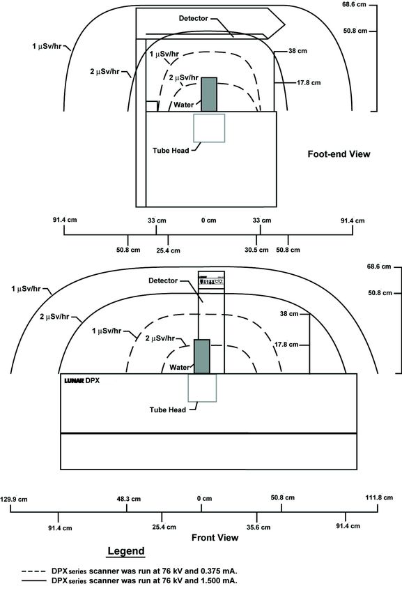
Scatter Radiation
The following display isodose diagrams of the Lunar iDXA full size scanner scatter radiation. The measurements conformed to the
IEC 60601-1-3:1994 standard and were taken with a Victoreen 6000-532 400cc Ion Chamber Paddle Probe. The beam was atten-
uated according to Clause 29.208.6 section a) which specifies a water target with dimensions 25x25x15 cm with container walls
equivalent to less than 1 cm of polymethyl-methacrylate (PMMA), otherwise known as Lucite. Each measurement consisted of a
static exposure at the maximum X-ray tube current and voltage of 2.5mA and 100kV.
- 23 of 57-Isodose diagram - Lunar iDXA Full Size Table
- 24 of 57-The following display isodose diagrams of the Lunar PRODIGY and PRODIGY Advance full size and compact scanner scatter radi-
ation. The measurements were taken with a Victoreen 470A. The beam was attenuated through a 20.32 cm water phantom.
- 25 of 57-Isodose diagram - Lunar PRODIGY, PRODIGY Advance, PRODIGY Primo, PRODIGY
Pro Full Size Table
- 26 of 57-Isodose diagram - Lunar PRODIGY, PRODIGY Advance, PRODIGY Primo, PRODIGY
Pro Compact Table
- 27 of 57-The following display isodose diagrams of scatter radiation for the full-size and compact Lunar DPX-NT/Pro and MD+ scanners,
the DPX Duo and DPX Bravo scanners. The measurements were taken with a Victoreen 470A. The beam was attenuated through
a 20.32 cm water phantom.
Isodose diagram - Lunar DPX-Pro/NT/MD+ Full Size Table
- 28 of 57-Isodose diagram - Lunar DPX-Pro/NT/MD+ Compact Size Table, DPX Duo and DPX
Bravo
- 29 of 57-System Maintenance
Clean Scanner Table Environment
Vacuum and dust the system site weekly. Dust the surface of the system regularly and use nonabrasive cleaners to remove dirt.
Do not let liquids inside the scanner table.
NOTE: DO NOT connect a vacuum cleaner to the same electrical outlet as the scanner.
WARNING: Proper cleaning and handling procedures must be followed to
prevent the possibility of cross-infections between subjects
scanned on the same system. Clean and disinfect the system
according to your local and country specific hygienic reg-
ulations. Protect table pad and table top from wetness and pre-
vent the ingress of liquid into the scanner by protectively covering
the scanner with a waterproof material.
CAUTION: Device software for investigational use on laboratory animal or
(Small Animal Option) for other tests that do not involve human subjects.
Unauthorized network access
Today, the delivery of healthcare to patients increasingly relies on modern information technology (IT) to electronically collect, proc-
ess, distribute, display, and store patient data. Any computer connected to a network is vulnerable to network virus and/or other
malicious attacks. Owners and operators of any medical device that is connected to a network are responsible for protecting their
computers from these malicious attacks.
Virus protection software with enCORE
You can protect your computers by following standard computer practices used for all information technology. Virus checker pro-
grams are an appropriate measure to assure electronic media and files are virus free before being introduced to your computer
or network. The latest operating system updates should also be installed. Contact your local GE representative for more infor-
mation. However, contact your service representative before performing any operating system update to assure full compatibility.
Active virus checker programs should be installed and active on the enCORE computer operating the bone densitometer. How-
ever, virus scanners have significant drawbacks including the following:
● Do not initiate an anti-virus scan when operating the bone densitometer. Certain files will be marked read-only.
● Anti-virus software may act inappropriately on false positives. Double check quarantine status before taking any per-
manent action. Medical image files can be damaged because the virus scanner attempts to fix what it falsely identified as
a virus.
● enCORE software may not operate properly if the virus scanner consumes too much memory or system resources.
Archive Image Files
Each day, archive new image files from your computer hard drive to an archive disk. This procedure creates free space on your
hard drive.
The program identifies archived files by labeling them with the drive location and the number of the archive disk: the program
begins with number 1. For example: the third archive disk located in drive A is labeled "A:A3." Labels for archive disks are shown in
the Label column of the Image file list on the Directory screen.
It is important that you label (write) the archive number on each archive disk. If it is necessary to restore archived files to the hard
drive or rebuild your database, the program requires that you use the appropriate archive disk(s) according to its label.
1. Select Directory from the Main screen or the Common tool bar.
2. Complete one of the procedures that follow:
- 30 of 57-● Archive all images for all patients-1) select Archive from the Directory tool bar and 2) select "Archive all images for
all patients" in the message box that is shown.
● Archive all exams for all patients in the current search results-1) select a search field from the dropdown menu,
2) enter search criteria in the field provided, 3) click the search button, 4) select Archive from the Directory tool bar, and
5) select "Archive all exams for all patients in the current search results" in the message box that is shown.
● Archive all images for selected patient-1) select a patient from the Patient List, 2) select Archive from the Directory
tool bar, and 3) select "Archive all images for selected patient" in the message box that is shown.
● Archive selected exam-1) select a patient from the Patient List, 2) select the patient image file you want to archive, 3)
select Archive from the Directory tool bar, and 4) select "Archive selected image" in the message box that is shown.
3. Select OK. The program archives the image files from the computer hard drive to the archive disk or external hard drive.
The archive number for the file is located in the Label column of the Image list.
4. If an archive storage source needs to be initiated, the program prompts you to insert a labeled archive disk in the appro-
priate disk drive. Insert a new or labeled disk as indicated.
NOTE: Refer to the enCORE Operator's Manual on changing the drive location used to archive files.
Test Emergency Stop Button
Test the emergency stop button once a month. Refer to the procedure that follows:
1. Start a standard total body measurement. Do not have a patient on the table.
2. Push the emergency stop button. Make sure the X-ray and Shutter lights are off and that a message on the computer
monitor indicates the emergency stop button is activated.
3. Push the emergency stop button again to reset the system (Prodigy Series, DPX-Pro/NT/MD+/Bravo/Duo only).
4. Do not save the patient measurement.
NOTE: If the emergency stop procedure does not work, call GE Medical Systems Lunar Support or your GE Medical Sys-
tems Lunar distributor.
Preventive Maintenance
X-ray tube and laser assemblies
There are NO USER-SERVICEABLE COMPONENTS inside the x-ray tube head and laser assemblies. DO NOT attempt on-site serv-
icing. Call GE Medical Systems Lunar Support or your GE Medical Systems Lunar distributor immediately if the system malfunctions.
DO NOT attempt to maintain or repair the components and scanner table. Doing so voids all current warranty and service con-
tracts.
Daily Quality Assurance procedure
Complete Quality Assurance procedures daily. Make sure each QA procedure passes. Refer to the enCORE Online Help for detailed
instructions.
If your system does not pass a test, check the position of the calibration block and complete the Quality Assurance procedure
again. If the procedure fails a second time, call GE Medical Systems Lunar Support or your GE Medical Systems Lunar distributor.
Annual maintenance
GE Medical Systems Lunar recommends that you schedule annual preventive maintenance from an authorized GE Medical Sys-
tems Lunar service engineer after your warranty period expires. Contact GE Medical Systems Lunar or your GE Medical Systems
- 31 of 57-Lunar distributor.
Dispose of Materials
The scanner contains lead (for x-ray shielding) and either sodium iodide or cadmium zinc telluride (used for x-ray detection).
WEEE Label: This symbol indicates that the waste of electrical and elec-
tronic
equipment must not be disposed as unsorted municipal waste and
must be collected separately. Please contact an authorized
representative of the manufacturer for information concerning the
decommissioning of your equipment.
If you contract with GE Medical Systems Lunar for the disposal of your scanner, GE Medical Systems Lunar will properly dispose of
these materials. If you choose to dispose of your scanner yourself, both substances must be disposed of in accordance with local
regulations. Contact your local GE representative for more information.
Space Requirements
For safety reasons, the computer and all peripherals must be in the same room with the scanner.
Lunar iDXA Full size Table
Standard room configuration: The computer and peripherals must be located more than 1.5 m or 1.83 m (U.S.A and Canada)
from the scanner. Recommended room dimensions are: 4.0 meters x 3.35 meters (13.2 feet x 11 feet)
Small room configuration: Room dimensions must be at least 3.2 m x 3.35 m if the computer and peripherals are powered by
an isolation transformer. Equipment powered by an isolation transformer can be located anywhere in the room with the scanner.
The isolation transformer and scanner must be plugged into the same dedicated line outlet.
- 32 of 57-You can also read