Parametric modeling of the aircraft electrical supply system for overall conceptual systems design
←
→
Page content transcription
If your browser does not render page correctly, please read the page content below
Deutscher Luft- und Raumfahrtkongress 2020
                                                    DocumentID: 530143

Parametric modeling of the aircraft electrical supply system for overall
                    conceptual systems design

                           T. Bielsky, M. Jünemann, F. Thielecke
          Hamburg University of Technology, Institute of Aircraft Systems Engineering
                          Nesspriel 5, 21129 Hamburg, Germany

                                                         Abstract
Owing to the ongoing endeavor to gradually improve aircraft operational efficiency with the use of electrified
on-board system concepts, computational modeling of the electric power supply system (EPSS) is becoming
an even more important element of the system design process. The rising complexity innate to the early
decision for an optimal system layout of such a More Electric Aircraft makes it necessary to use integrated
and physics-based system models to study most promising concepts from an overall systems and aircraft
level perspective. In this paper, a parametric model of the EPSS is presented, which is implemented into the
overall systems design environment GeneSys. The parametric approach of the proposed method not only
allows to evaluate promising architecture variants but also has the flexibility to study the effect of topological
design decisions (positioning, routing) on system-level metrics. This includes routines for knowledge-based
and automated generation of the EPSS topology based on parametric geometry information of the aircraft. In
addition, a component-based system sizing and steady-state simulation process is used to estimate mass and
electric load profile of the system for a given flight trajectory. To demonstrate the implemented model, the result
of three exemplary topology studies are discussed.

1.   INTRODUCTION                                                With the trend towards an increased on-board electri-
                                                                 fication, specifically the design of the electric power
                                                                 supply system (EPSS) is becoming more complex,
The benefits and drawbacks of an electrified on-board            because the number of (safety-critical) electric con-
systems architecture for future aircraft has been dis-           sumers connected to the EPSS and their range of
cussed for decades [1]. However, literature still draws          electric power demand will further increase [5]. A
a disagreeing picture on which extent the further elec-          respective component-based network model for the
trification might contribute to the reduction of cost fac-       EPSS that covers the required design complexity of
tors like assembly, maintenance, or fuel burn during             electrified architectures has, however, not been im-
aircraft operations. This stems, among others, from              plemented into GeneSys so far.
an increased level of interdependence between sys-               To find a suitable layout for the EPSS, early con-
tems and a growing significance of coupling effects              cept studies using physics-based sizing and simula-
with other aircraft design disciplines like engine, aero-        tion models for such complex supply networks have
dynamics, structures, or production. The rising com-             to be performed. In essence, two questions are an-
plexity innate to the design of such More Electric Air-          swered by these studies:
craft (MEA) makes it necessary to use integrated and
physics-based system models for concept studies on               1. Which power sources (Engine, Fuel Cell, Battery,
an overall systems and aircraft level.                              etc.) should be deployed to provide electrical
To this end, the Institute of Aircraft Systems Engi-                power under all relevant operating conditions and
neering (FST) at Hamburg University of Technology                   how is the power share defined during these sce-
(TUHH) has developed the GeneSys framework. It                      narios?
supports overall systems design (OSD) studies based
on a parametric and component-based system mod-                  2. How should the supply networks be specified with
eling approach [2, 3, 4]. GeneSys comprises a set of                respect to the number of redundant networks, type
sizing and steady-state simulation modules for sev-                 of power (AC, DC), grid structure (centralized, de-
eral aircraft systems which have a relevant impact on               centralized) and topology (positioning, routing)?
aircraft level metrics like mission fuel burn. These sys-
tems are both consumer systems (e.g. environmental               The first question is closely related to the design and
control, flight control) and their respective power sup-         selection of propulsion concepts and the overall (pri-
ply networks (electric, hydraulic, pneumatic).                   mary and secondary) power supply layout in general.

©2021                                                        1                                         doi: 10.25967/530143
Deutscher Luft- und Raumfahrtkongress 2020
The second question is more specific as it aims at ar- In larger passenger airplanes, the voltage is gener-
chitectural decisions on overall systems level, namely ated as a three-phase electric current [7]. Some con-
the layout of the electrical generation and distribution sumer systems require a supply of a single-phase
system to supply power for electric consumer aboard electric current or a direct current. This applies for
the aircraft. To answer the first question, it is neces- instance to cockpit systems and lights. Components
sary to initially integrate methods that can answer the such as transformer rectifier units (TRUs) which are
second question. part of the PEPDC, are used to adapt the voltage type
In this paper, the integration of an EPSS model for and voltage level from alternating current to direct cur-
OSD is presented, which is suitable to perform stud- rent [8].
ies related to the second question. It constitutes the The difference to a more decentralized architecture
basis for a future model extension for more complex of a modern EPSS essentially applies for consumer
studies pertaining to both issues. To this end, a para- systems which are both non-critical for flight and do
metric model of the EPSS is integrated into GeneSys not require high electrical loads [9]. The motivation
which has the flexibility to perform automated topo- to replace the centralized system by a decentralized
logical layout studies on system level based on pre- system is a decrease of the total cable length and a
defined network specifications. This includes an al- more efficient power management system [6]. An ex-
gorithm for knowledge-based and automated gener- ample of a modern EPSS architecture is displayed in
ation of the EPSS topology based on parametric ge- Figure 1. The generators at the main engines and
ometry information of the aircraft. The generation of a at the auxiliary power unit (APU) which is located in
topology is proceeded by a component-based system the aft fuselage are directly connected to the PEPDC.
sizing and steady-state simulation process. The PEPDC supplies electric power to the secondary
The paper is structured as followed. In section 2, power distribution boxes (SPDBs) which are located
the general layout of modern EPSS is described. in the cabin area. The SPDBs supply the consumer
The parametric model of the EPSS is elaborated in components in the cabin and cargo area which are
section 3. The GeneSys framework and the integra- located closest to the particular SPDB [6, 10].
tion of the EPSS model is described in section 4. The The secondary power distribution center (SEPDC),
sizing process and three exemplary topology studies which supplies safety-uncritical consumer systems
are presented in section 5. with reduced power requirements [6, 10], and the
SPDB were introduced in the Airbus A380 [9] and
continued to be developed in modern system archi-
tecture layouts such as in the Boeing 787 and Airbus
2. LAYOUT OF A MODERN ELECTRIC POWER
A350 [8, 11]. The SEPDC and SPDBs contain solid-
SUPPLY SYSTEM state power controllers (SSPC) that replace the me-
chanically triggered CBPs [8]. The SSPCs provide
The architecture of an aircraft EPSS typically consists a digital and automatic load protection and switch-
of power generation units, power distribution units, ing functionality [5]. The PEPDC is also directly con-
and the wiring harnesses. These cables and com- nected to the SEPDC.
ponents are used to distribute the electric power to
all on-board consumer systems. In addition, some
of these components include converters to adapt the
voltage level and voltage type of individual power lines
or networks.
Older EPSS architectures were arranged in a central-
ized manner, which is also one of the most signifi-
cant differences from more modern architectures [6].
Within these conventional architectures, the gener- Generator
ated power is transported to the primary power dis- Primary Power Distribution Center (PEPDC)
Secondary Power Distribution Box (SPDB)
tribution center (PEPDC) which is located in the elec-
tronic bay in the front of the fuselage [6]. From there,
FIGURE 1. EPSS architecture of MEA
the electric power is distributed to all electrical con-
sumer systems in the aircraft. Before the electric
power is supplied to each consumer system, it passes A decentralized arrangement of the EPSS system
circuit breaker panels (CBP) which are typically lo- opens up the design space for number and location
cated in the front and in the rear of the aircraft [6]. of distribution units. It is therefore necessary to op-
Circuit breakers are protection devices to avoid an timize these topological degrees of freedom with the
electrical overload. In case of an overload, the circuit objective to reduce system mass.
breaker opens the circuit mechanically [5]. Proposals for newer EPSS architectures for all elec-
©2021 2Deutscher Luft- und Raumfahrtkongress 2020
tric aircraft (AEA) include the usage of high voltage phase shift. So far, average values for phase shift
direct current (HVDC) to supply consumer systems are included in the power requirements as a simplistic
with electric power [11, 12, 13]. Because some AEA representation of the power calculation of alternating
concepts include, for example, fuel cells and batter- current consumer systems. Approaches to optimize
ies as direct current power sources to supply aircraft the system by actively changing the respective phase
on-board systems, the voltage does not need to be conductor to minimize the total phase shift (cf. [8])
transformed into alternating current for an HVDC net- are not part of the approach of the EPSS sizing in this
work. For electrical consumers, which use alternating paper and will be part of future implementations.
current, DC power is converted to AC with locally in- Based on the data of the ELA, the distribution net-
stalled inverters at the respective consumer. This may work is sized. The transmitted power is propagated
apply to consumer systems such as motors [11]. from consumer systems via distribution components
to the generators to select required cables. The type
and diameter of a cable segment is selected based
3. PARAMETRIC MODELING OF THE EPSS on the requirement that a certain connection must not
exceed a specified voltage drop. This voltage drop
depends on the resistance of the cable that is largely
The methodology, which is applied to perform EPSS
influenced by the length, diameter, and material of a
sizing, is presented in the following. It is based on
particular cable connection. The voltage drop require-
the approach for conceptual sizing of aircraft systems
ment depends on the nominal voltage level of the par-
using physics-based system models, which has been
ticular connection [15]. Table 1 shows some examples
proposed by Koeppen [2] and Liscouet-Hanke [14].
of the allowed voltage drop, which are dependent on
The underlying pattern of this sizing approach is to
the voltage level defined by the Society of Automo-
perform the system sizing by propagating power re-
tive Engineers (SAE) in the guideline ARD50055 [15].
quirements from power sinks (here: electric con-
The voltage drop for other voltage levels is extrapo-
sumers) to power sources (here: generators, batter-
lated from the given values in Table 1.
ies). In addition, different operation modes, such as
normal operations or one engine inoperative (OEI),
are analyzed. For example, in the system architec- TAB 1. Allowed voltage drop dependent on the nomi-
ture shown in Figure 1, the connection to the Aux- nal voltage [15]
iliary Power Unit (APU) would not be considered by
Nominal System Allowable voltage drop
only assessing the operation mode normal operations
Voltage [V] (continuous operation) [V]
because during this mode, the electric power is sup-
28 1
plied by the main engine generators (cf. Table 4).
115 4
Moreover, the available power is decreased in emer-
200 7
gency situations such as OEI without available back-
up systems such as the APU. If in this case the power
requirements surpass the available power, the load The voltage drop is calculated according to
of non-essential systems, such as Galleys or cabin Equation 1 and Equation 2, which are based on cal-
lights, can be partly or fully shed to be able to sup- culation rules for electrical series circuits and Ohm’s
ply at least all essential systems with the remaining law [16, 17]. The calculation of the cable resistance
power sources [2, 14]. consists of two parts. The first part is the calcula-
The first step of the system sizing process is to per- tion of the specific resistance of the cable Rcable,spec
form electrical load analyzes (ELA) for different oper- which is the resistance per unit of length given by the
ation modes to determine the electrical loads of con- manufacturer multiplied by the length of the cable,
sumer systems. The ELA includes information about which is known from the system topology. The sec-
the voltage level, the voltage type, the load require- ond part of the calculation of the cable resistance is
ments over a flight mission, and the maximum re- the consideration of the temperature dependency of
quired load for every consumer system [6]. the resistance. This is considered by the difference
Furthermore, consumer systems which are supplied of an assumed maximum temperature of the cable
by alternating current can create an inductive or a ca- T and the ambient temperature T0 . The difference
pacitive current which leads to a phase shift within the is multiplied with the temperature coefficient α which
distribution network. Because of such phase shifts, depends on the material of the cable. The calcula-
reactive power requirements are added to the ef- tion of the voltage drop Udrop in Equation 1 considers
fective power requirements of the system, which in- the maximum electric current Imax which is calculated
creases the total power requirements at the genera- in Equation 2. The maximum electric current results
tors. These phase shifts are also included in the ELA from the maximum propagated electric power flow
to determine possibilities to connect these systems Pconsumer,max and the nominal voltage Uconsumer , that is
within the distribution network to minimize the total available for the consumer system after considering
©2021 3Deutscher Luft- und Raumfahrtkongress 2020
the voltage drop Udrop . Both parameters are an output TAB 2. Power-to-weight ratio of on-board aircraft
of the ELA. converters and switches [13, 12, 20]
Component type Power-to-weight ratio
kg
TRU 0.4 kW
(1) Udrop = Rcable,spec · lcable · (1 + α (T − T0 )) · Imax kg
DC converter 0.3 kW
kg
AC converter 0.35 kW
kg
SSPC 2 kW
Pconsumer,max Pconsumer,max
(2) Imax = =
Uconsumer Uspec −Udrop
According to Equation 4, the mass of the PEPDC is
In this approach, the specific parameters of the cables the sum of all power converters that are located in
are obtained from a database containing commercial the PEPDC. The calculation of the mass depends on
off-the-shelf cables [18]. The database is searched the maximum power Pconv,max for each converter, and
for cables that fulfill the voltage drop requirements ac- on an empirical calibration factor ΨPEPDC to account
cording to cable resistance, the applied voltage type for materials and other electric components within the
and voltage level, and the maximum required power. PEPDC. A further correction factor ΨP,offset is added
At the same time, the considered cables should be as to the PEPDC to compensate for consumer systems
lightweight as possible. If a cable conforms to these which are not considered in the EPSS sizing during
conditions, it is chosen and selected for the consid- the conceptual design phase. According to Koeppen,
ered cable segment. The calculation of the voltage an offset value of ΨP,offset = 1.1 is a reasonable as-
drop is repeated for each connection between a dis- sumption [2].
tribution unit and a consumer system and for connec-
tions between distribution units. The cables between
the generators and the PEPDC are calculated based
(4)
on the constraint that the voltage drop should not ex-
NConverter
ceed two percent of the voltage level [15].
mPEPDC = ΨPEPDC · ΨP,offset · ∑ Pconv,max,i · mconv,spec,i
This approach of selecting cables allows to determine i=1
both the mass of the cable and the power losses due
to the voltage drop. It is assumed that connections of The mass of the SPDBs is calculated in Equation 5.
all voltage types share the same return current path This equation also considers the integrated SSPC
via the aircraft fuselage or the electrical structure net- unit which is sized according to the maximum power
work (ESN) [8]. Furthermore, modern EPSS architec- PSPDB,max and the power-to-weight ratio of the SSPC
tures are supplied by a variable frequency (VF) vary- as shown in Table 2. An empricial correction fac-
ing between 360 Hz and 760 Hz [5]. This provokes ef- tor ΨSPDB is also considered, taking into account for
fects on the cable selection such as the skin effect, materials and other electric components within the
which needs to be considered as well [19]. However, SPDB. The mass of the SEPDC can also be calcu-
this effect is neglected in the presented approach and lated according to Equation 5 as well, since the mode
is part of future implementations. of operation of the SEPDC is similar to the one of the
SPDBs [5].
As shown in Equation 3, the mass of all considered
cables of the EPSS is the sum of the length of the re-
spective cable lcable and the specific mass mcable,spec of
(5) mSPDB = ΨSPDB · PSPDB,max · mSSPC,spec
the cable selected from the database.
The mass of the power generation units can be esti-
Ncables mated with empirical formulas such as Equation 6 for
(3) mcables = ∑ lcable,i · mcable,spec,i the mass of a generator that provides a three-phase
i=1 alternating current at a voltage level of 200/115V .
Equation 7 can be applied to calculate the mass
The mass of the components with a significant effect of a generator that provides a voltage level of
on the total mass are the units for changing the volt- 400/230V [17]. Table 3 displays the constant values
age type and voltage level, such as TRUs or invert- for the mass calculation as presented in Equation 6
ers, power distribution units, such as the PEPDC or and Equation 7.
SPDBs, and power generation units. The mass of the
power converters is calculated by power-to-weight ra-
tios [13, 12] and are displayed exemplary in Table 2. (6) mgen,115V = Pgen,115V · k1 + k2
©2021 4Deutscher Luft- und Raumfahrtkongress 2020
4. OVERALL CONCEPTUAL DESIGN OF ON-
(7) mgen,230V = Pgen,230V · k3 + k4 BOARD SYSTEMS
During conceptual design phase, the fidelity of on-
board system models increases gradually throughout
the design process. Typically, the process starts with
TAB 3. Empiric values for calculating the generator an initial aircraft layout provided by overall aircraft de-
masses [17] sign (OAD). To obtain first estimates of the parame-
ters which are relevant for OAD iterations like system
Constant type Value
mass and secondary power demand, simple regres-
k1 3.16 · 10−4 VA
kg
sion functions are used. As maturity of the aircraft
k2 29.53 kg concept progresses, detailed system design (DSD)
k3 2.55 · 10−4 VA
kg
of relevant aircraft on-board systems is conducted by
k4 30.14 kg dynamic simulations of system behavior and use of
other high-fidelity analysis methods. The set-up of
these detailed models, however, consumes develop-
ment resources and requires the systems architecture
to be already defined. Thus, architectural and topo-
logical trade-off studies with DSD models are consid-
The last step of the sizing process is to calculate
erably limited. It is necessary to conduct these type
the total mass mEPSS of the system. As shown in
of studies on a specific level of model abstraction,
Equation 8, the total mass is the sum of the mass of
namely on the Overall Systems Design (OSD) level,
the selected cables and of the mass of the compo-
at which fidelity of system models and the complexity
nents such as the generators and distribution units.
of architectural design choices from an overall sys-
Furthermore, an additional factor Ψcable,offset is added
tems and aircraft perspective are balanced.
to compensate for the mass of the cable connections
of consumer systems which are not considered in the
conceptual design phase. This offset is calculated
based on an empirical function, which depends on the
assumed share of the total power requirements of the &ROODE
included consumer systems. 2YHUDOO$LUFUDIW
'HVLJQ
&3$&6,QWHUIDFH
(8) mEPSS = mcomponents + Ψcable,offset · mcable 2$'OHYHO
26'OHYHO
0HWKRGRORJ\
After completing the sizing process, a steady-state %
6ODWV
*
*
<
simulation is performed based on the designed sys-
< * )ODSV * <
% %
< <
* *
* *
% %
(
* * <
7+6
<
%
(0$
tem and a given flight trajectory. During the steady-
* <
% %
*Deutscher Luft- und Raumfahrtkongress 2020
tems architectures. The process is structured to be prise, for instance, the type and number of compo-
both flexible to perform integrated iteration loops with nents, the assignment to aircraft structural groups
OAD-level and comprehensive to integrate physics- (e.g. wing, fuselage), and specifications about inputs
based sizing and steady-state simulation models de- and outputs of functional system components (e.g.
rived from the DSD stage [4]. The related taxonomy of power, data).
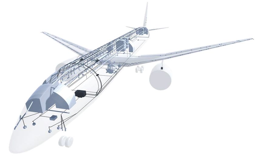
the described design stages is illustrated in Figure 2. As a next step, knowledge-based algorithms exploit
Based on the initial aircraft lofting provided by OAD, these configuration data and CPACS information to
the overall systems architecture and its topology can automatically generate a first layout of the system
be defined to refine initial estimates for system param- topology — that is, components are located and
eters like mass or secondary power demand. To this power conductors are routed according to predefined
end, parametric and component-based system mod- layouts (topology templates) by the algorithm. Topol-
els of relevant consumer systems (e.g. environmen- ogy information are saved in a dedicated XML file
tal control, flight control) and their respective power (sysArchXML) which is standardized according to a
supply networks (electric, hydraulic, pneumatic) are parametric ontology for conceptual design of aircraft
used [2, 3]. Relevant data is communicated via stan- on-board systems. Aircraft geometry and system
dardized XML-interfaces. As shown in Figure 2, data topology can be visualized to check and adapt the ini-
is exchanged with the OAD process via the dedicated tially generated topology (cf. Figure 5).
XML-standard "Common Language for Aircraft De-
Having defined and generated the topology, the sys-
sign" (CPACS) [21]. The CPACS file contains a para-
tem is sized and its behavior is simulated. For sys-
metric geometry model and performance data from
tems that in any way transmit power or provide a
other disciplines like aerodynamics and propulsion
mass flow between functional components, the sys-
design.
tem is modeled as a graph directed from power gen-
Figure 3 shows the generic sizing process of a repre-
erators to power consumers. Based on predefined
sentative system module in GeneSys. The process is
operational scenarios involving cases of failure, the
divided into four consecutive steps: Pre-processing,
required power or mass flow and respective state
topology generation, sizing and simulation, and post-
variables in network segments are propagated back-
processing.
wards from consumers to generators. Hereby, the
most critical case that is relevant for sizing can be
3UHSURFHVVLQJ identified. Thereupon, system power consumption
5HDGFKHFNLQSXW and required mass flows are simulated for a given
aircraft mission trajectory using steady-state behav-
'HILQHDUFKLWHFWXUH
ior models considering power losses in transmission
7RSRORJ\ JHQHUDWLRQ 9DU\DUFKLWHFWXUH lines and functional components.
FRPSRQHQWVSRVLWLRQLQJ GHILQLWLRQ To perform architectural or topological studies, the ini-
tial parametric definition of the architecture has to be
FRQQHFWLRQVURXWLQJ
9LVXDOV\VWHP
WRSRORJ\
changed systematically. This can be automated us-
6L]LQJDQG6LPXODWLRQ
J
YHULILFDWLRQ
ing a wrapper module that modifies the configuration
&UHDWHV\VWHPJUDSK
V\VWHP file and executes the sizing process for each defined
RQWRORJ\
variant. Hereby, both the system architecture by, for
$QDO\VH V\VWHPV example, changing the general layout of used com-
6L]LQJ ponents and the system topology by, for instance,
changing number or location of a specific component
&21 ',6 *(1 can be object of study.
6LPXODWLRQ
3RVWSURFHVVLQJ
S
ZULWHRXWSXW
5. TOPOLOGY STUDIES FOR A MODERN EPSS
FIGURE 3. Process diagram of the design process The system sizing process of the EPSS according to
of the EPSS based on the GeneSys framework Figure 3 is presented in the following. This includes
the description of the problem set-up and the con-
During pre-processing, system architecture and rele- sideration of boundary conditions of operational sce-
vant boundary conditions for the sizing process are narios for system sizing. Afterwards, the results of a
defined manually. These definitions are based on a study on three different topological concepts are de-
functional description of the system layout and com- scribed.
©2021 6Deutscher Luft- und Raumfahrtkongress 2020
5.1. Problem set-up type and voltage level is converted to the required
voltage type and voltage level of the consumer sys-
In the following, the problem set-up is described stat- tems. Consumer systems that need to be supplied
ing the reference aircraft and the reference system by a single phase alternating current are connected
architecture which are used to perform the sizing pro- to one phase of the particular three-phase alternat-
cess and the concept studies. ing current network. The PEPDC supplies electrical
loads to consumer systems which are either flight crit-
ical systems, require high loads with a maximum cur-
5.1.1. Reference aircraft rent above 15 A [8], or require a three-phase alternat-
ing current feed-in [8]. This includes the supply of the
To perform the EPSS sizing process and concept SPDBs and SEPDC, as shown in Figure 4.
studies, the reference aircraft architecture of the As shown in Figure 4, the architecture of the
federal aviation research program (LuFo) AdVanced ARB2028 contains a Ram Air Turbine (RAT) that
Aircraft CONcepts (AVACON) is used [22]. The would supply the essential electrical systems during
AVACON reference aircraft is the research baseline an operation mode in which it is assumed that all other
2028 (ARB2028) which is a mid-range aircraft de- generators are inoperative [5]. All non-essential con-
signed for 285 passengers with a system architecture sumer systems are shed in this operation mode. Con-
based on the design of a state-of-the-art MEA. sidering the selected operation modes for the sys-
tem sizing process (cf. Table 4), all of them have
an influence on the sizing of the network that is con-
5.1.2. Reference systems architecture nected to the cabin consumer systems because the
non-essential consumer systems are not fully shed.
The layout of the on-board systems of the ARB2028 is In the context of the concept studies presented, the
in general based on a modern more-electric systems operation mode in which only the RAT supplies the
architecture as part of the MEA concept [4]. This also essential loads is neglected because it does not have
applies to the EPSS architecture, which is compara- a significant influence on the results.
ble to the system layout of the Airbus A350. The en-
gine generators provide three-phase alternating cur-
rent with variable frequency (VF) at a voltage level ENG APU RAT ENG
of 400 V between two phases. Within the PEPDC,
power is converted to a second three-phase alter- GEN GEN GEN GEN
nating current with an AC-AC converter at a voltage
level of 200 V between two phases with a constant
frequency of 400 Hz. All available voltage levels and
voltage types are:
• 400/230 V AC / VF PEPDC
• 200/115 V AC / 400 Hz SEPDC
• 28 V DC
Less Power Consumer
The ARB2028 is a twin-engine aircraft. Due to the
regulations of extended operations (ETOPS) [23], the SPDB
availability of system components has to be at a level
to ensure safe operations during failure cases such
as OEI. To ensure the required level of safe opera- High Power Consumer Cabin/Cargo Consumer
tions, 2 generators are located at each main engine
and at the APU. Furthermore, the reference architec- Three-phase alternating current
ture contains 2 PEPDCs which are located in the elec- Single-phase alternating current
tronic bay underneath the cockpit, 2 SEPDCs which Direct current
are located next to the PEPDCs, 6 SPDBs which are
distributed in the cabin, and 2 SPDBs which are dis- FIGURE 4. Schematic layout of a modern EPSS
tributed in the cargo area.
The simplified structure of the system architecture
with the above-mentioned components of the EPSS 5.2. Topology generation
is shown in Figure 4. All generators are connected
to the PEPDC from where the electric power is dis- To use the automated positioning and routing algo-
tributed into the aircraft. At the PEPDC, the voltage rithms of the GeneSys framework, the EPSS ar-
©2021 7Deutscher Luft- und Raumfahrtkongress 2020
(OHFWULFPRWRU SXPSV
+\GUDXOLF V\VWHP )OLJKWFRQWURO V\VWHP
63'%V
&DELQ HOHFWURQLFV
&DELQ PRGXOHV
/DYDWRULHV*DOOH\V *HQHUDWRU
,QWHULRUDQGH[WHULRU OLJKWLQJ
3(3'&
6(3'&
$YLRQLFV
)DQVDQGYHQWLODWRUV
(OHFWULFDO SRZHUVXSSO\ V\VWHP
&RQVXPHUV\VWHPV
FIGURE 5. System topology of the electric power supply system and relevant consumer systems
chitecture for the ARB2028, which is described in cabin electronics, and the interior and exterior light-
subsection 5.1, must be predefined by the systems ing. Figure 5 shows the resulting system topology
engineer in a configuration file. This file includes in- with the consumer systems that are connected to the
formation about the number of components, the ge- EPSS within the ARB2028 systems architecture.
ometric information about each system component, Based on the previously defined systems architec-
and the information about the input and output param- ture, the system topology is generated based on in-
eters for each system component as it is elaborated formation about the aircraft and on the positioning of
in section 4. The required information for the configu- system components and connections. Figure 5 also
ration file with a definition of a system architecture are serves as visual verification of the positioning heuris-
exemplified in Appendix A. In this example, the EPSS tics. The generators are located at the engines, the
consists of 4 generators, 1 PEPDC, 2 SPDBs, and 2 PEPDCs are located in the front area of the fuselage
galleys which represent the consumer systems. The and the SPDBs are distributed in the cabin. The con-
generators are located at the aircraft engines, the lo- nection of the consumer systems to the EPSS are vi-
cation of the PEPDC is defined to be in the electronic sualized by cables, which are routed along typical ca-
bay in the front of the fuselage, and the SPDBs are ble routing spaces in the aircraft. These cable routing
located in the cabin. Each component is functionally spaces are among others in the triangle area under-
assigned to an electrical network. The nominal volt- neath the cabin floor, above the cabin area, and along
age level and voltage type required by the respective the wing spars.
consumer system is also specified.
To simplify the sizing process during the conceptual
design phase, the consumer systems are limited to 5.3. System sizing
systems with a significant share in the total required
electric power. It is assumed that these systems rep- The sizing process of the EPSS is based on the ap-
resent 90 % of the total required electric power. These proach presented in section 3. With the generated
consumer systems are the actuators of the flight con- system topology, a graph of the EPSS is created. The
trol system, the galleys, the fans of the environmen- graph is directed and indicates the power flow from
tal control system, the ice and rain protection system, the sources of the graph to its sinks. Following the
the electric motor pumps of the hydraulic power sup- description from section 3, the sources of the graph
ply system, the fuel pumps, the avionic systems, the represent the power sources of the EPSS and the end
©2021 8Deutscher Luft- und Raumfahrtkongress 2020
nodes represent the power sinks. Hence, the direc- required power for serving a meal and drinks to each
tion of the graph is defined according to the power passenger. The peak in the middle of the flight mis-
flow, while the system sizing is oriented in the oppo- sion represents the required power for serving drinks
site direction. Table 4 shows the list of considered op- only.
eration modes to perform the EPSS sizing. These
operation modes are chosen as the relevant sizing $OWLWXGH (OHFWULFSRZHU
cases for the studies in subsection 5.4.
3HO >N:@
+ >IW@
TAB 4. List of operation modes (sizing cases) and
respective active power supply components which
are considered during system sizing process.
W>@
Operation Mode Power Supply Components (a) Electrical load profile - time-independent
Normal Operations GENL ∧ GENR
$OWLWXGH (OHFWULFSRZHU
OEI + APU avail. (GENL ∨ GENR ) ∧ GENAPU
3HO >N:@
+ >IW@
OEI GENL ∨ GENR
The first step is to generate the ELA of all considered
consumer systems that are connected to the EPSS. W>@
The power requirements of the consumer systems
are generated by executing system analysis modules (b) Electrical load profile - mission segment resolution
of relevant consumer systems. The load profiles of $OWLWXGH (OHFWULFSRZHU
3HO >N9$@
the generated power requirements are classified into
+ >IW@
three different types, which differentiate themselves
by the accuracy of the load profiles as displayed in
Figure 6. The calculation of the required electric
power of different systems depends on the level of W>@
detail of the system model. Furthermore, the power
calculation also depends on the need to evaluate the (c) Electrical load profile - temporal resolution
system in high level of details. This is the case, when,
FIGURE 6. Electrical load profiles of different con-
for example, the share of the required power of a sys-
sumer systems
tem compared to the overall provided power is signif-
icant.
The first type of load model is a time-independent load After allocating the power requirements to each con-
representation, which is displayed in Figure 6a. This sumer system, the sizing parameters of the EPSS,
type of load profile represents consumer systems with which are the required power of each consumer sys-
an approximately constant load requirement during tem and the voltage type and voltage level, are prop-
the flight mission, such as flight computers of the agated through the system graph of the distribution
avionic systems. network. With the propagation of these parameters,
Figure 6b shows a load profile which depends on the maximum power requirements are estimated in
the flight mission segment. This type of load profile each network segment. The cables for each connec-
comprises changes of power requirements at differ- tion can then be selected from the database as de-
ent flight phases. An example is the power consump- scribed in section 3.
tion of the internal and external lights. For instance, After analyzing the distribution system considering all
the power peaks in the beginning and in the end of consumer system loads and power losses over the
the flight mission are caused by the activation of the cables and voltage transformer units, the total load
landing lights at altitudes below 10, 000 ft. profile of the EPSS is calculated. The total load pro-
The third type of load profile is dependent on the flight file represents the electric power which has to be sup-
mission and on the actual flight time. This type of load plied by all active power supply units. In case of
profile is displayed in Figure 6c and is typical for rep- the operation mode normal operations, the power is
resenting the required loads of the galleys. The galley supplied by all engine generators. The resulting to-
loads are calculated with a system module that simu- tal load profile of the ARB2028 aircraft is displayed
lates the galleys based on parameters like the number in Figure 7. It also shows the load profile of the OEI
of seats in the cabin, the cabin configuration, and the operation mode with two remaining operating gener-
amount of meals served during the flight. As shown ators. Non-essential consumer systems, such as the
in Figure 6c, there are three power peaks during the Galleys (cf. Figure 6c) are shed according to defined
flight mission. The first and last peak represent the load shedding schemes.
©2021 9Deutscher Luft- und Raumfahrtkongress 2020
In addition to the determination of the total electric 2 to 16. The position of SPDBs and their distance
required power of the EPSS, the mass needs to be to each other is evenly distributed along the cabin by
calculated as a relevant evaluation metric for the pre- the positioning algorithm, as can be seen in Figure 8.
liminary sizing process. The mass is calculated ac- The number of SPDBs is increased by 2 with each
cording to the methods presented in section 3. To de- iteration step, because the positioning heuristic of
termine the usage of voltage converter units, it is as- GeneSys is designed to allocate the SPDBs symmet-
sumed that a voltage converter unit is required, if the rically along the x-z-plane in the cabin.
power specification of a functional component has dif-
ferent input and output voltage type and voltage level.
$OWLWXGH (OHFWULFSRZHU ߟ୳ୱୣ
(OHFWULFSRZHU FDELQ ORDGV VKHG ͲǤͳͷ
3HO >N9$@
+ >IW@
PEPDC SPDB
W>@
FIGURE 8. Positioning of relevant components of the
EPSS that are part of study 1 (number of SPDBs)
FIGURE 7. Total load profile of the EPSS
5.4. Examples of possible topology studies The results of the first study are shown in Figure 9.
In Figure 9a, the mass of the electrical network of
Through the integration of the EPSS sizing module in
the cabin is depicted. The total mass is divided into
GeneSys, concept studies can be performed to find a
the cable mass and the mass of the SPDBs. In the
suitable layout for the system architecture. To explore
first step, a simplification of the model is assumed,
the topological sensitivities of the EPSS, three topol-
which includes that the mass of the SPDBs is con-
ogy studies are conducted and discussed. An addi-
stant. Hence, the total mass of all SPDBs linearly
tional wrapper module changes the definition of the
increases with the number of SPDBs. The mass of
system architecture in the configuration file and exe-
the cables is decreasing with the number of SPDBs.
cutes the sizing process for each considered layout.
This stems from the algorithmic routing of the cables
In the presented study, number and location of sev-
between SPDBs and consumer systems. If the num-
eral components are modified. The parameter sys-
ber of SPDBs increases, the total cable distance from
tem mass is used as the evaluation metric for all three
the SPDBs to the consumer system components de-
studies. The three conducted topology studies are
creases. According to the total mass, the optimum is
listed in the following.
reached at 6 SPDBs.
1. Adaption of the electrical network of the cabin by However, the layout with the minimum mass in
varying the number of SPDBs Figure 9a is not distinctive. The total mass of archi-
2. Variation of the PEPDC location and adaption of tectures with 2, 4, or 8 SPDBs lies in a similar range
the electrical network of the cabin (study 1) for with a deviation of 4.7 %, 2.5 %, and 0.5 % from the cal-
each PEPDC location culated minimum, respectively. If one considers that
uncertainty is inherent to this values due to model
3. Adding a second PEPDC and varying its location simplifications, a decision about the optimal number
while adapting the electrical network of the cabin of SPDBs has to be substantiated with more detailed
(study 1) for each location of the second PEPDC analyses. For the presented models, uncertainties
are introduced by neglecting system components with
The topology studies are analyzed and discussed in minor contribution to the system mass.
detail in the following.
Moreover, the choice of the input parameter Ψcable,offset
according to Equation 8 affects the mass of the elec-
5.4.1. Study 1: Number of SPDBs trical network within the cabin significantly. This is il-
lustrated by Figure 9b where the results of the study
With the first study, the topological layout of power is shown, for which a constant offset of 20 % is added
controllers for cabin electrical consumers is exam- to the cable mass. In this case, the optimum number
ined. To this end, the number of SPDBs is varied from of SPDBs is calculated at nSPDB,opt = 8.
©2021 10Deutscher Luft- und Raumfahrtkongress 2020
SPDBs. The decrease of the SSPC mass due to the
0DVV 63'%V 0DVV &DEOHV 7RWDO0DVV reduced number of ports of each SPDB is illustrated
in Figure 9c. In consideration of adapting the mass
1RUPDOL]HG PDVV
of the SSPCs, the optimum number of SPDBs in the
cabin changes from nSPDB,opt = 6 to nSPDB,opt = 8 and
the total mass decreases by 2 %.
The results of the above presented cases about the
sensitivity of the optimum mass of the electrical cabin
network show that an optimum number of SPDBs
cannot be clearly determined due to uncertainties
1XPEHURI63'%VLQFDELQ during the early design stage. In the case of the pre-
sented EPSS of the ARB2028 aircraft, the optimum
(a) Mass of the cabin electronics with constant component number range of SPDBs in the cabin is between 4
mass of the SPDBs and 10. Because more SPDBs would significantly in-
crease the total mass and enhance the system com-
plexity, it is unlikely that more than 10 SPDBs are in-
tegrated.
1RUPDOL]HG PDVV
,QFUHDVHG &DEOH0DVV
5.4.2. Study 2: Number of SPDBs and location of
7RWDO0DVV ,QFUHDVHG
PEPDC
1XPEHURI63'%VLQFDELQ
The mass optimization of the EPSS by varying the
location of all primary and secondary distribution net-
work components is considered in the second study.
(b) Correction of the mass of the cabin electronics due to Since the PEPDC is typically located in the front of
possible neglect of cables the fuselage, long power lines have to be routed from
the engine generators and the APU generators to the
'HFUHDVHG 63'%0DVV 7RWDO0DVV 'HFUHDVHG PEPDC. Also, the galley which is located in the aft
1RUPDOL]HG PDVV
fuselage is one of the consumer systems with the
highest power requirements. Because galley feeder
lines are heavy due to the high power requirements,
it is examined, if the relocation of the PEPDC to-
wards the aft fuselage might decrease the length
of the cables and the total system mass. As illus-
trated in Figure 10, the PEPDC is iteratively moved
backwards until it is located at 80 % of the fuselage
1XPEHURI63'%VLQFDELQ
length. In addition, the optimization described in
subsubsection 5.4.1 for study 1 is performed for each
(c) Mass of the cabin electronics with varying component location of the PEPDC.
mass of the SPDBs The results of the second study are shown in
Figure 11. Figure 11a displays the total mass of
FIGURE 9. Results of study 1: Sensitivities when
the EPSS for three selected locations of the PEPDC,
changing the number of SPDBs, their masses and
which are at 15 %, 50 %, and 80 % of the fuselage
the cable masses
length. The curve of the total mass of each PEPDC
location depends on the number of SPDBs. While the
Another source of uncertainty is the assumption that total mass of the EPSS is similar when the PEPDC is
the mass of an SPDB is constant. An increment in located either in the front or rear of the fuselage, the
the number of SPDBs can decrease the number of total mass of the EPSS is lower when the PEPDC is
cabin consumer systems which are connected to one located in the middle of the fuselage. This is caused
SPDB. It might be the case, that the mass of the by shorter cable distance to the generators or con-
SPDBs decreases due to reduced number of ports sumer systems with high power requirements, such
on each SPDB and due to a reduced maximum re- as the galley in the aft cabin. The optimum number
quired power supply. According to Equation 5, a re- of SPDBs is 2 in this case. According to the design
duced maximum required power supply would have heuristics in GeneSys, these two SPDBs would be lo-
an influence on the sizing of the SSPCs inside the cated in the center of the cabin above the PEPDC.
©2021 11Deutscher Luft- und Raumfahrtkongress 2020
analyzed. For example, the air of the electronic bay
ߟ୳ୱୣ
ͲǤͶ ͲǤ7 ͲǤ8
is conditioned accordingly. To cool the components
ͲǤͳͷ ͲǤ͵ ͲǤͷ ͲǤ6
such as voltage transformers within the PEPDC, the
air of the new location of the PEPDC needs to be
conditioned as well. In addition, the relocation of the
PEPDC SPDB PEPDC might be constrained by the available instal-
lation space, which has not been considered for the
presented study.
To sum up, the location of the PEPDC in front of the
FIGURE 10. Positioning of relevant components of
fuselage is advantageous because it is connected to
the EPSS including adaptions of the PEPDC loca-
many critical consumer systems, such as the flight
tions for study 2 (number of SPDBs and location of
computer and cockpit avionic systems, which are lo-
PEPDC)
cated in the electronic bay as well. In this case, the
cable distances to these consumer systems are de-
creased. However, the location of the PEPDC in the
center of the fuselage is also advantageous because
7RWDO0DVV ሺߟ ൌ ͲǤͳͷሻ
7RWDO0DVV ሺߟ ൌ ͲǤͺሻ
7RWDO0DVV ሺߟ ൌ ͲǤͷሻ
the mass of the power lines from the generators and
to the galley in the aft fuselage is decreased. To com-
1RUPDOL]HG PDVV
bine these effects, a second PEPDC is added to the
system architecture in the following study.
5.4.3. Study 3: Adding a second PEPDC
1XPEHURI63'%VLQFDELQ A second PEPDC is added to the EPSS in this study.
As shown in Figure 12, one PEPDC is located in the
(a) Mass of the EPSS when changing the number of front of the fuselage and remains unchanged while
SPDBs and changing the location of the PEPDC (relative the location of the second PEPDC is varied from 30 %
location of PEPDC in bracket) to 80 % of the fuselage length. As presented in study
1, the number of SPDBs is also varied between 2 and
0DVV &RPSRQHQWV 0DVV &DEOHV 7RWDO0DVV 16 for each location of the second PEPDC. The gen-
erator cables and the consumer systems in the aft
1RUPDOL]HG PDVV
fuselage are supplied by the second PEPDC. The first
PEPDC supplies the flight critical systems in the elec-
tronic bay and the consumer systems in the front of
the fuselage. The advantage of this layout is the re-
duction of cable length for consumers with high power
requirements.
5HODWLYHSRVLWLRQ RI3(3'&
ߟ୳ୱୣ
ͲǤͳͷ ͲǤ͵ ͲǤͶ ͲǤͷ ͲǤ6 ͲǤ7 ͲǤ8
(b) Total mass of the EPSS at different PEPDC locations
with optimum number of SPDBs in each case
FIGURE 11. Sensitivities due to changes in the loca- PEPDC SPDB
tion of the PEPDC
The calculated masses of all analyzed PEPDC loca-
tions are shown in Figure 11b. The optimum number FIGURE 12. Positioning of relevant components of
of SPDBs is stated at each location of the PEPDC. the EPSS including adaptions of the second PEPDC
Again, a distinctive optimum is not evident. However, locations for study 3 (adding a second PEPDC)
it can be concluded that reduction of the EPSS to-
tal mass can be expected, if the PEPDC is relocated The results of this study are illustrated in Figure 13.
in the range between 30 % and 50 % of the fuselage The mass of the SPDBs and of the cables which con-
length. nect the cabin consumer systems to the SPDBs if
Shifting the PEPDC towards the center of the fuse- the second PEPDC is located at 30 % of the fuselage
lage seems advantageous if only the system mass is length is shown in Figure 13a. In this case, the op-
©2021 12Deutscher Luft- und Raumfahrtkongress 2020
timum number of SPDBs in the cabin is 4, but the fuselage length. If the second PEPDC is located in
minimum is also not distinctive. the aft fuselage, the total mass increases.
The total mass of all analyzed locations of the sec-
ond PEPDC is shown in Figure 13c. The optimum
number of SPDBs is stated at each analyzed loca-
tion of the second PEPDC. In this case, the optimum
1RUPDOL]HG PDVV
location of the second PEPDC can be expected be-
tween 30 % and 50 % of the fuselage length, while the
optimum amount of SPDBs varies between 4 and 6.
However, the second PEPDC has a high impact on
the total mass and leads to a higher total mass of the
0DVV 63'%V 0DVV &DEOHV 7RWDO0DVV EPSS compared to the topology with one PEPDC. As
shown in Figure 11b and Figure 13c, the mass of the
1XPEHURI63'%VLQFDELQ optimum location of the second PEPDC lies in a simi-
lar range as the second-highest mass of the topology
(a) Mass of the cabin electronics with constant component with one PEPDC (η = 0.7).
mass of the SPDBs having added a second PEPDC at
30 % of the fuselage length
5.5. Discussion of results
Parametric topology studies were performed to iden-
1RUPDOL]HG PDVV
tify the optimum number and location of components
of the EPSS with the objective to decrease the total
system mass. In general, the results of the performed
topology studies have a rather small impact on the
7RWDO0DVV ሺߟ ൌ ͲǤ͵ሻ 7RWDO0DVV ሺߟ ൌ ͲǤͷሻ potential to optimize the EPSS. Because the uncer-
7RWDO0DVV ሺߟ ൌ ͲǤͺሻ
tainties in earlier design stages are high, the results
of early studies that do not show a dominant design
1XPEHURI63'%VLQFDELQ solution should rather be grasped as tendencies and
have to be further analyzed in a more detailed design
(b) Mass of the EPSS when changing the number of stage. The second and third study have also shown
SPDBs and changing the location of the second PEPDC that not only one parameter should be considered for
optimizing the system. Changing the position of the
PEPDC is affected by the available installation space
and the availability of air conditioning to cool the elec-
1RUPDOL]HG PDVV
trical components of the PEPDC.
Nevertheless, the presented studies demonstrate,
that the use of a parametric modeling framework like
GeneSys allows a systematic and automated assess-
ment of system architectures and their topological
0DVV &RPSRQHQWV 0DVV &DEOHV 7RWDO0DVV layouts. However, they also demonstrate that inter-
dependencies between systems already exist in the
5HODWLYHSRVLWLRQRIVHFRQG3(3'& scope of the presented simplified topology studies. To
increase the significance of the presented results, an
(c) Total mass of the EPSS at different locations of the sec- integrated assessment is necessary.
ond PEPDC with optimum number of SPDBs in each case
FIGURE 13. Sensitivities due to changes in the loca- 6. SUMMARY AND CONCLUSION
tion of a second PEPDC
In this paper, a methodology for a component-based
The total mass of the EPSS for three selected lo- network model for the design of the electric power
cations of the second PEPDC, which are at 30 %, supply system has been presented. Apart from the
50 %, and 80 % of the fuselage length is shown in capability to perform the sizing and simulation of the
Figure 13b. For each location of the second PEPDC, electric power supply system in the conceptual design
the number of SPDBs is varied. The result of the op- phase, concept studies are conducted to find a suit-
timum mass is similar for the arrangement in which able layout for the system architecture. The method-
the second PEPDC is located at 30 % and 50 % of the ology is included in the GeneSys framework, which
©2021 13Deutscher Luft- und Raumfahrtkongress 2020
comprises a set of sizing and steady-state simula- [2] Carsten Koeppen. Methodik zur modell-
tion modules for aircraft on-board systems to perform basierten Prognose von Flugzeugsystempara-
overall systems design. metern im Vorentwurf von Verkehrsflugzeugen.
To this end, the integration of the electric power sup- Aachen: Shaker Verlag, 2006.
ply system into GeneSys includes the parametric def- [3] Riko Bornholdt, Tobias Kreitz, and Frank Thi-
inition of the system architecture and the implemen- elecke. “Function-Driven Design and Evaluation
tation of positioning heuristics such as knowledge- of Innovative Flight Controls and Power System
based topology templates to generate the system Architectures”. In: SAE Technical Paper Series.
topology. Also, the procedure for system sizing of SAE International, 2015.
the electrical network has been described. A graph-
based representation of the system topology is cre- [4] M. Jünemann, F. Thielecke, F. Peter, M. Hor-
ated for the sizing process. This representation is nung, F. Schültke, and E. Stumpf. “Methodology
used, according to the design process of the electric for Design and Evaluation of More Electric Air-
power supply system, to propagate system parame- craft Systems Architectures within the AVACON
ters through the network. The propagation of sys- Project”. In: German Aerospace Congress,
tem parameters is performed for all defined operation 2019.
modes (sizing cases). [5] Ian Moir and Allan Seabridge. Aircraft Sys-
The proposed approach for sizing of the electric tems: Mechanical, electrical, and avionics sub-
power supply system within GeneSys opens up new systems integration. Chichester: John Wiley &
functionalities, which have been exemplified. Among Sons Ltd., 2008.
others, one of the functionalities is to perform auto-
[6] B. Nya, J. Brombach, T. Schröter, and D.
mated topology studies with a given solution space.
Schulz. “Weight evaluation of cabin power ar-
Thus, effects on the aircraft systems due to concep-
chitecture on smaller civil aircraft”. In: 3rd In-
tual changes on aircraft level can directly be evalu-
ternational Workshop on Aircraft System Tech-
ated. In this paper, this was demonstrated by three
nologies (AST 2011), 2011.
simplistic topology studies in which the number and
location of components of the electric power supply [7] D. Calinski, U. B. Carl, and C. Koeppen. “Prog-
system were varied. However, it has been shown that nose des Leistungsbedarfs und der Masse
no dominant topological layout can be identified with elektrischer Bordnetze im Flugzeugentwurf”. In:
engineering models for the early design stage. In this German Aerospace Congress, 2003.
case, more detailed models for the system sizing pro- [8] Michael Terörde, Housam Wattar, and Detlef
cess are needed, which might be able to reduce the Schulz. “Phase balancing for aircraft electri-
existing uncertainties in the model and in the assump- cal distribution systems”. In: IEEE Transactions
tions of the parameters. on Aerospace and Electronic Systems 51.3
(2015), pp. 1781–1792.
[9] Torben Schröter. Power Management on Air-
ACKNOWLEDGEMENT craft. Berlin: VDE Verlag GmbH, 2013.
[10] J. Brombach, A. Lücken, D. Schulz, and
The results of the presented paper are part of the T. Schröter. “Strukturelle und funktionale
work in the research project development of systems Verbesserung der elektrischen Energiev-
and components for electrified flight (ESBEF), which erteilung moderner Verkehrsflugzeuge”. In:
is supported by the Federal Ministry of Economic Af- German Aerospace Congress, 2010.
fairs and Energy in the national LuFo VI program. Any [11] Hendrik Schefer, Leon Fauth, Tobias H. Kopp,
opinions, findings and conclusions expressed in this Regine Mallwitz, Jens Friebe, and Michael Kur-
document are those of the authors and do not neces- rat. “Discussion on Electric Power Supply Sys-
sarily reflect the views of the other project partners. tems for All Electric Aircraft”. In: IEEE, 2020.
[12] Johannes Brombach, Arno Lucken, Brice
Nya, Martin Johannsen, and Detlef Schulz.
BIBLIOGRAPHY “Comparison of different electrical HVDC-
architectures for aircraft application”. In: IEEE,
[1] R I Jones. “The more electric aircraft— 2012.
assessing the benefits”. In: Proceedings of [13] J. Brombach, T. Schröter, A. Lücken, and D.
the Institution of Mechanical Engineers, Part Schulz. “Optimized Cabin Power Supply with a
G: Journal of Aerospace Engineering 216.5 +/- 270 V DC Grid on a Modern Aircraft”. In:
(2002), pp. 259–269. IEEE, 2007.
©2021 14You can also read