Dell EMC PowerSwitch Z9432F-ON Installation Guide - August 2021
←
→
Page content transcription
If your browser does not render page correctly, please read the page content below
Dell EMC PowerSwitch Z9432F-ON
Installation Guide
August 2021

August 2021
Rev. A01
Notes, cautions, and warnings

     NOTE: A NOTE indicates important information that helps you make better use of your product.

     CAUTION: A CAUTION indicates either potential damage to hardware or loss of data and tells you how to avoid
     the problem.

     WARNING: A WARNING indicates a potential for property damage, personal injury, or death.

© 2021 Dell Inc. or its subsidiaries. All rights reserved. Dell, EMC, and other trademarks are trademarks of Dell Inc. or its subsidiaries. Other
trademarks may be trademarks of their respective owners.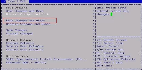
Contents

Chapter 1: About this guide........................................................................................................... 5
  Related documents............................................................................................................................................................. 5
  Information symbols............................................................................................................................................................6

Chapter 2: The Z9432F-ON switch................................................................................................ 7
  Introduction........................................................................................................................................................................... 7
  Features................................................................................................................................................................................. 8
  Physical dimensions.............................................................................................................................................................8
  LED display............................................................................................................................................................................ 9
      LED behavior...................................................................................................................................................................9
  Prerequisites....................................................................................................................................................................... 10
  Z9432F-ON switch configurations................................................................................................................................. 11
  Luggage tag......................................................................................................................................................................... 11

Chapter 3: Site preparations........................................................................................................ 12
  Site selection.......................................................................................................................................................................12
  Cabinet placement............................................................................................................................................................. 12
  Rack mounting.................................................................................................................................................................... 13
  Switch ground.....................................................................................................................................................................13
  Fans and airflow................................................................................................................................................................. 13
  Switch power...................................................................................................................................................................... 14
  Storing components.......................................................................................................................................................... 14

Chapter 4: Z9432F-ON switch installation................................................................................... 15
  Attach a ground cable.......................................................................................................................................................15
  Rack or cabinet hardware installation procedure.......................................................................................................16
  Switch installation..............................................................................................................................................................16
     Four-post ReadyRail installation............................................................................................................................... 16
     Four-post L-bracket rail installation........................................................................................................................22
  Optics installation..............................................................................................................................................................26
     Optics removal............................................................................................................................................................. 27
  Switch startup....................................................................................................................................................................27
  After switch placement....................................................................................................................................................27
  Switch replacement.......................................................................................................................................................... 27

Chapter 5: Power supplies...........................................................................................................29
  Components....................................................................................................................................................................... 29
  AC or DC power supply installation.............................................................................................................................. 30
  AC or DC power supply replacement............................................................................................................................ 31
  DC power connections......................................................................................................................................................31

Chapter 6: Fans...........................................................................................................................34
  Components....................................................................................................................................................................... 34
  Fan module installation.....................................................................................................................................................35

                                                                                                                                                               Contents                    3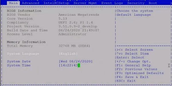
Fan module replacement................................................................................................................................................. 35
Chapter 7: Management ports..................................................................................................... 36
RJ45 console port access............................................................................................................................................... 36
Micro-USB Type-B console port access..................................................................................................................... 36
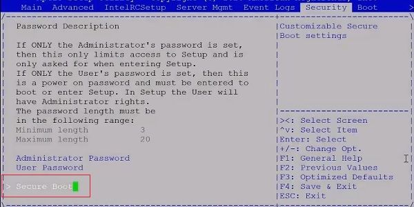
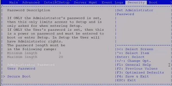
Chapter 8: Secure boot............................................................................................................... 38
Enable BIOS secure boot.................................................................................................................................................38
Disable BIOS secure boot.................................................................................................................................................41
Chapter 9: Before you install an operating system.......................................................................45
Check your switch............................................................................................................................................................ 46
ONIE service discovery....................................................................................................................................................46
Chapter 10: Specifications...........................................................................................................47
Chassis physical design.................................................................................................................................................... 47
IEEE standards................................................................................................................................................................... 48
Agency compliance........................................................................................................................................................... 49
USA Federal Communications Commission statement............................................................................................ 49
European Union EMC directive conformance statement........................................................................................49
Japan VCCI compliance for class A equipment......................................................................................................... 50
Safety standards and compliance agency certifications......................................................................................... 50
Electromagnetic compatibility ....................................................................................................................................... 51
Product recycling and disposal....................................................................................................................................... 51
Chapter 11: Dell EMC support...................................................................................................... 53
4 Contents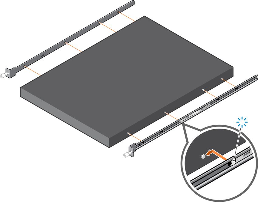
1
                                                                                  About this guide
This guide provides site preparation recommendations, step-by-step procedures for rack mounting and desk mounting your
switch, inserting modules, and connecting to a power source.
    CAUTION: To avoid electrostatic discharge (ESD) damage, wear grounding wrist straps when handling this
    equipment.

    NOTE: Only trained and qualified personnel can install this equipment. Read this guide before you install and power up this
    equipment. This equipment contains two power cables. Disconnect both power cables before servicing.

    NOTE: This equipment contains optical transceivers, which comply with the limits of Class 1 laser radiation.

    Figure 1. Class 1 laser product tag

    NOTE: When no cable is connected, visible and invisible laser radiation may emit from the aperture of the optical
    transceiver ports. Avoid exposure to laser radiation. Do not stare into open apertures.

Regulatory information
Marketing model Z9432F-ON is represented by the regulatory model E46W and the regulatory type E46W001.

BMC, ONIE, and DIAG OS default login
After you have installed and powered up your switch, you must enter the default username and password.
● Username (BMC): admin
● Username (ONIE and DIAG OS): root
● Password (uppercase): !
Topics:
•   Related documents
•   Information symbols

Related documents
For more information about the Z9432F-ON switch, see the following documents:
● Dell EMC SmartFabric OS10 User Guide
● Dell EMC SmartFabric OS10 Release Notes
● Dell EMC PowerSwitch Z9432F-ON Set-up Guide
● Dell EMC PowerSwitch Z9432F-ON Release Notes

                                                                                                      About this guide            5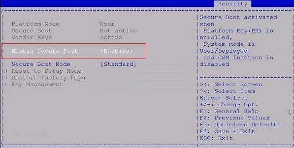
●   Dell EMC PowerSwitch Z9432F-ON BMC User Guide
●   Open Networking Hardware Diagnostic Guide
●   Enterprise SONiC Distribution by Dell Technologies User Guide
●   Release Notes for Enterprise SONiC Distribution by Dell Technologies
     NOTE: To access product documentation for specific Dell EMC PowerSwitches, see the Dell EMC Networking OS10 Info
     Hub. For all other resources, see Dell EMC support: www.dell.com/support.

Information symbols
This book uses the following information symbols:
    NOTE: The Note icon signals important operational information.

    CAUTION: The Caution icon signals information about situations that could result in equipment damage or loss
    of data.

    CAUTION: The ESD Warning icon requires that you take electrostatic precautions when handling the device.

    WARNING: The Warning icon signals information about hardware handling that could result in injury.

6       About this guide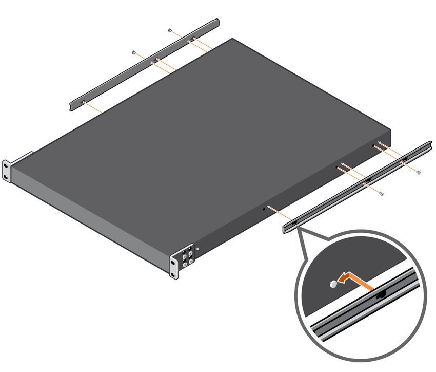
2
                                                            The Z9432F-ON switch
The following sections describe the Dell EMC Z9432F-ON switch.
Topics:
•   Introduction
•   Features
•   Physical dimensions
•   LED display
•   Prerequisites
•   Z9432F-ON switch configurations
•   Luggage tag

Introduction
The Z9432F-ON switch is a 1U, full-featured fixed 10/25/40/50/100/200/400 GbE data center switch with 400 GbE optical
interfaces for data center leaf aggregation. The Z9432F-ON supports 32 quad small form-factor pluggable 56-DD (QSFP56-DD)
400 GbE ports and two small form-factor pluggable plus (SFP+) ports. This switch is also usable as 25/50/100 GbE switch
using 25/50/100 GbE breakout for connections to switches, servers, and storage.
    CAUTION: Switches with fan airflow from the PSU to the I/O—reverse airflow—are subject to tighter
    restrictions for power consumption on cables and optics that are used for 400 GbE ports. Reverse airflow
    switches do not support high-power cables or optics. 400 GbE transceivers and active cables may exceed the
    supported threshold. For more information, see the Dell EMC PowerSwitch with High-Power Optics guide.

    CAUTION: Review the optics specification sheet and the switch data sheet to understand which models support
    airflow from the I/O to the PSU (normal) and which support airflow from the PSU to I/O (reverse).
The Z9432F-ON switch has seven fans and two AC or DC PSUs. The switch also has one RJ45 serial console port, one
Micro-USB type-B console port, one 10/100/1000 Base-T Ethernet management port, and one USB type-A port for the external
storage. Management ports are on the I/O-side of the switch.
    NOTE: Redundant AC power requires high-line 200 VAC to 240 VAC. Using low-line 120 VAC does not provide redundancy
    for the switch.
The Z9432F-ON switch supports the following optic configurations:
●   32 x 400 GbE—QSFP56-DD
●   64 x 200 GbE—QSFP56
●   128 x 100 GbE—QSFP56-DD & 4xQSFP28
●   128 x 100 GbE—QSFP56-DD & 4xSFP-DD
●   128 x 40 GbE—QSFP56-DD & 4xQSFP+
●   128 x 25 GbE
●   128 x 10 GbE
The Z9432F-ON switch I/O-side view:

                                                                                         The Z9432F-ON switch            7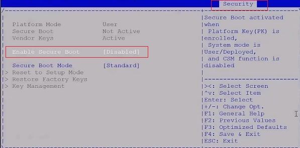
1.   Two SFP+ ports                                           2.   Thirty-two QSFP56-DD ports
3.   RJ45 Ethernet port                                       4.   LED status icons
5.   USB Type A                                               6.   Luggage tag
7.   RJ45 console port                                        8.   MicroUSB-B console port

The Z9432F-ON switch PSU-side view:

1. AC PSUs
2. Fan modules

Features
The Z9432F-ON switch offers the following features:
●    Thirty-two 400GbE QSFP56-DD ports
●    Two SFP+ ports
●    One MicroUSB-B console port
●    One RJ45 console port
●    One RJ45 Ethernet port
●    One USB Type A port for more file storage
●    Eight-core Intel Denverton-NS central processing unit (CPU) system with 2.2 GHz C3758
●    One 10/100/1000BaseT Ethernet management port
●    Temperature monitoring
●    Software-readable thermal monitor
●    Real-time clock (RTC) support
●    Two hot-pluggable redundant AC or DC PSUs
●    Seven hot-pluggable replaceable fan modules
●    Power management monitoring
●    Two-hole ground lug

Physical dimensions
The Z9332F-ON switch has the following physical dimensions:
● 438.5 x 550 x 43 mm (W x D x H)
● 17.26 x 21.65 x 1.693 inches (W x D x H)
  ○ PSU handle 29.3 mm (1.15 in)
  ○ PSU latch 34.6 mm (1.37 in)

8        The Z9432F-ON switch
○ Fan tray handle 25 mm (0.99 in)

LED display
The Z9432F-ON switch includes LED displays on the I/O side of the switch. This section describes open networking installation
environment (ONIE) LED behaviors. Some LED behaviors may change after you install your software.

LED behavior
The following Z9432F-ON switch LED behavior is seen during ONIE operations:

1.   SFP+ Port Activity LED                                    2. Port Activity LED
3.   RJ45 Ethernet Port LED                                    4. System LED
5.   Power LED                                                 6. Fan LED
7.   Locator LED

Table 1. Z9432F-ON switch LED behavior
LED                                                             Description
System Status/Health LED                                        ●   Off—No power
                                                                ●   Solid green—Normal operation
                                                                ●   Flashing green—Booting
                                                                ●   Solid yellow—Critical system error
                                                                ●   Flashing yellow—Noncritical system error, fan failure, or
                                                                    power supply failure
Power LED                                                       ●   Off—No power
                                                                ●   Solid Green—Normal operation
                                                                ●   Solid yellow—POST is in process
                                                                ●   Flashing yellow—Power supply fault
FAN LED                                                         ● Off—No power
                                                                ● Solid green—Normal operation; fan powered and running
                                                                  at the expected RPM
                                                                ● Flashing yellow—Fan fault—including incompatible airflow
                                                                  direction when you insert the PSU or fan trays with
                                                                  differing airflows
PSU LED                                                         ● Off—No power
                                                                ● Solid green—Normal operation
                                                                ● Flashing yellow—PSU warning event; power continues to
                                                                  operate
                                                                ● Flashing green—4Hz with five times on and off: Mismatch
                                                                ● Flashing green—Firmware update

                                                                                              The Z9432F-ON switch              9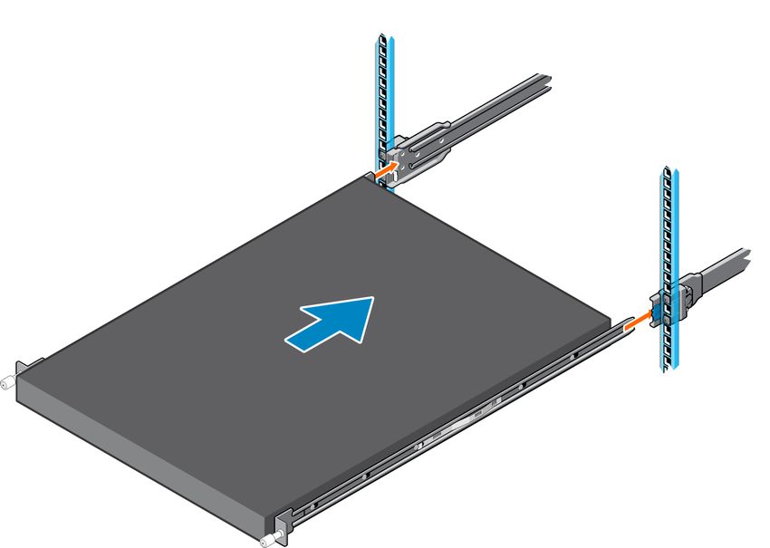
Table 1. Z9432F-ON switch LED behavior (continued)
LED                                                                Description
LOCATOR LED/System Beacon                                          ● Off—Locator function disabled
                                                                   ● Flashing blue—Locator function enabled

Table 2. System management Ethernet port LED
LED                                                                Description
Link LED                                                           ●   Off—No module present
                                                                   ●   Solid green—Port link is up
                                                                   ●   Solid yellow—Module needs attention using the CLI.
                                                                   ●   Flashing yellow, one second on; one second off—Port
                                                                       beacon
Activity LED                                                       ● Off—No activity
                                                                   ● Flashing green—Port activity

Table 3. Z9432F-ON QSFP56-DD port LED
LED                                                                Description
Link/Activity LED                                                  ●   Off—No link/activity
                                                                   ●   Solid green—Port link is up
                                                                   ●   Flashing green ~30ms—Port activity operating
                                                                   ●   Solid yellow—Use CLI to check LED status

Table 4. SFP+ port LED
LED                                                                Description
Link LED                                                           ●   Off—No link
                                                                   ●   Solid green—Link operating at maximum speed, 10G
                                                                   ●   Flashing green—Port activity at maximum speed
                                                                   ●   Solid yellow—Link operating at a lower speed,1G
Activity LED                                                       ● Off—No link
                                                                   ● Flashing green—port activity

Prerequisites
The following is a list of components that are required for successful switch installation:

     NOTE: For detailed installation instructions, see Site preparations and Z9432F-ON switch installation.

● Z9432F-ON switch or multiple switches, if stacking
● AC or DC country- and regional-specific cables to connect the AC or DC power source to each of the switch AC or DC
   power supplies
● Rail mounting brackets for rack installation, included
● Screws for rack installation, not included
● #1 and #2 Phillips screw drivers, not included
● Torx screwdriver, not included
● Ground cable screws for L-bracket, included
● Copper/fiber cables
Other optional components are:
● Ground cable and lug for the frame-end of the ground cable
● Extra mounting brackets
● Extra power supply unit
● Extra fan module

10       The Z9432F-ON switch
NOTE: The DC ground lug kit ships with the other accessories inside the shipping box.
Z9432F-ON switch configurations
You can order the Z9432F-ON switch in several different configurations.
● Z9432F-ON AC or DC Normal Airflow switch:
○ One U, 32 x 400 GbE QSFP56-DD ports, two SFP+ ports, two AC or DC power supplies, and seven fan subsystems with
airflow from the I/O side to the power supply side
● Z9432F-ON AC or DC Reverse Airflow switch:
○ One U, 32 x 400 GbE QSFP56-DD ports, two SFP+ ports, two AC or DC power supplies, and seven fan subsystems with
airflow from the power supply side to the I/O
● Fan with airflow from the I/O side to the PSU side—normal airflow
● Fan with airflow from the PSU side to the I/O side—reverse airflow
● AC or DC power supply with airflow from the I/O side to the PSU side—normal airflow
● AC or DC power supply with airflow from the PSU side to the I/O side—reverse airflow
CAUTION: Switches with fan airflow from the PSU to the I/O—reverse airflow—are subject to tighter
restrictions for power consumption on cables and optics that are used for 400 GbE ports. Reverse airflow
switches do not support high-power cables or optics. 400 GbE transceivers and active cables may exceed the
supported threshold. For more information, see the Dell EMC PowerSwitch with High-Power Optics guide.
CAUTION: Review the optics specification sheet and the switch data sheet to understand which models support
airflow from the I/O to the PSU (normal) and which support airflow from the PSU to I/O (reverse).
Luggage tag
The switch has a pull-out tag, which is known as a luggage tag. The front of the luggage tag includes switch ID information. The
back of the luggage tag includes a QRL that takes you to a How-To site where you can watch videos about racking the switch,
replacing components, configuring port channels, and so on.
1. Dell EMC QRL 2. Country of origin and DP/N QRL
3. Service tag QRL 4. MAC address QRL
5. Express service tag QRL 6. BMC MAC address
The Z9432F-ON switch 113
Site preparations
The Z9432F-ON switch is suitable for installation as part of a common bond network (CBN).
You can install the switch in:
● Network telecommunication facilities
● Data centers
● Other locations where the National Electric Code (NEC) applies
CAUTION: To avoid tangling cables or damaging optics, install the switch into a rack or cabinet before installing
any additional components such as cables or optics.
Topics:
• Site selection
• Cabinet placement
• Rack mounting
• Switch ground
• Fans and airflow
• Switch power
• Storing components
Site selection
Install the switch equipment in restricted access areas.
A restricted access area is one in which service personnel can only gain access using a special tool, lock, key or other means of
security. The authority responsible for the location controls access to the restricted area.
Ensure that the area where you install your switch meets the following safety requirements:
● Near an adequate power source. Connect the switch to the appropriate branch circuit protection according to your local
electrical codes.
● Switch environmental temperature range is from 0° to 45°C (32° to 113°F).
● Relative humidity is from 5 to 90 percent noncondensing.
● In a dry, clean, well-ventilated, and temperature-controlled room, away from heat sources such as hot air vents or direct
sunlight
● Away from sources of severe electromagnetic noise
● Inside the restricted access area that is positioned in a rack or cabinet, or on a desktop with adequate space in the front,
back, and sides for proper ventilation and access
● Install the switch in Information Technology Rooms in accordance with Article 645 of the National Electrical Code and NFPA
75.
● Install the switch in an environment that meets all region- or country-specific occupational safety and health requirements.
For more information about switch storage and environmental temperatures, see Specifications.
Cabinet placement
Install the Z9432F-ON switch only in indoor cabinets that are designed for use in a controlled environment.
Do not install the switch in outside cabinets. For cabinet placement requirements, see Site selection.
The cabinet must meet minimum size requirements. Airflow must be in accordance with the Electronic Industries Alliance (EIA)
standard. Ensure that there is a minimum of 12.7 cm (5 inches) between the intake and exhaust vents and the cabinet wall.
12 Site preparationsRack mounting
When you prepare your equipment rack, ensure that the rack is grounded.
Ground the equipment rack to the same ground point the power service in your area uses. The ground path must be permanent.
Switch ground
Dell Technologies recommends you ground your switch. Use the Z9432F-ON switch in a common bond network (CBN).
Connect the grounding cables as described in Z9432F-ON switch installation.
NOTE: For an AC-powered switch, although the third conductor of the AC power cable provides a ground path, Dell
Technologies recommends grounding your switch with a dedicated ground wire.
NOTE: For a DC-powered switch, the only way to safely ground your switch is to attach a dedicated ground wire. The
ground lug ships inside the DC PSU shipping box. The two ground lug screws ship attached to the switch. Before you install
the DC switch in a rack, attach the ground lug to the switch using the included screws. Next attach the DC ground wire to
the ground lug. The DC-powered switch ships with the DC ground lug and screws.
Fans and airflow
The Z9432F-ON switch fans support two airflow options: normal and reverse.
Fan combinations
Fan installation is done as part of the factory install based on stock keeping unit (SKU) type. The Z9432F-ON switch has SKUs
that support the following configurations:
● AC PSU with fan airflow from the I/O to the PSU—normal—the red indicator is the normal airflow direction.
● DC PSU with fan airflow from the I/O to the PSU—normal—the red indicator is the normal airflow direction.
With the addition of the fan reversal kit, the Z9432F-ON switch has SKUs that also support the following configurations:
● AC PSU with fan airflow from the PSU to the I/O—reverse—the blue indicator is the reverse airflow direction.
● DC PSU with fan airflow from the PSU to the I/O—reverse—the blue indicator is the reverse airflow direction.
Order the fans suitable to support your site ventilation. Use a single type of fan airflow.
CAUTION: Switches with fan airflow from the PSU to the I/O—reverse airflow—are subject to tighter
restrictions for power consumption on cables and optics that are used for 400 GbE ports. Reverse airflow
switches do not support high-power cables or optics. 400 GbE transceivers and active cables may exceed the
supported threshold.
CAUTION: To avoid damage to the switch, fan and PSU airflow directions must match. Do not mix normal and
reverse airflows in a single switch.
For proper ventilation, position the switch in an equipment rack or cabinet with a minimum of 12.7 cm (5 inches) of clearance
around the exhaust vents. When you install two Z9432F-ON switches near each other, to permit proper airflow, position the
two switches at least 12.7 cm (5 inches) apart. The fan speed varies based on internal temperature monitoring. The Z9432F-ON
switch never intentionally turns off the fans.
For more information, see Fans.
Site preparations 13Switch power
To connect the switch to the applicable power source, use the appropriate power cable. An AC power cable is included with
each PSU.
When installing AC or DC switches, follow the code requirements appropriate for your country or region. For example, in the
U.S., follow National Electrical Code ANSI/NFPA 70 and in Europe follow IEC60364.
The switch powers-up when the power cable connects the switch to the power source. For more information, see Power
supplies.
CAUTION: To avoid equipment damage, always disconnect the power cables before you service the power supply
slots. The switch has multiple power cables. Before servicing, disconnect all power cables.
CAUTION: On an AC switch, the main power disconnect device is the power supply cable. Ensure that the socket
outlet is located or installed near the equipment and is easily accessible.
NOTE: Redundant AC power requires high-line 200 VAC to 240 VAC. Using low-line 120 VAC does not provide redundancy
for the switch.
NOTE: You do not see module LEDs when the switch powers up in ONIE as the software controls the modules.
Storing components
If you do not install your Z9432F-ON switch and components immediately, properly store the switch and all components using
these guidelines:
● Storage location temperature must remain constant. The storage range is from -40°C to 70°C (-40° to 158°F).
● Store on a dry surface or floor, away from direct sunlight, heat, and air conditioning ducts.
● Store in a dust-free environment.
CAUTION: ESD damage can occur when components are mishandled. Always wear an ESD-preventive wrist
or heel ground strap when handling the Z9432F-ON switch and accessories. After you remove the original
packaging, place the Z9432F-ON switch and components on an anti-static surface.
14 Site preparations4
Z9432F-ON switch installation
To install the Z9432F-ON switch, complete the installation procedures in the order given.
Before unpacking the switch, inspect the container and immediately report any evidence of damage.
CAUTION: ESD damage can occur if components are mishandled. Always wear an ESD-preventive wrist or heel
ground strap when handling the Z9432F-ON switch and components. As with all electrical devices of this type,
take all the necessary safety precautions to prevent injury when installing this switch.
Always handle the switch and components with care. Avoid dropping the switch or its field replaceable units (FRUs).
Topics:
• Attach a ground cable
• Rack or cabinet hardware installation procedure
• Switch installation
• Optics installation
• Switch startup
• After switch placement
• Switch replacement
Attach a ground cable
To attach a ground cable to the switch, use the included M4 screws.
CAUTION: Grounding conductors must be made of copper. Copper conductors offer better conductivity and
durability. Do not use aluminum conductors.
CAUTION: For an AC-powered switch, although the third conductor of the AC power cable provides a ground
path, Dell Technologies recommends grounding your switch with a dedicated ground wire. Using a dedicated
ground wire reduces equipment communication interference, offers ESD protection, and prevents possible
equipment damage.
CAUTION: For a DC-powered switch, the only way to safely ground your switch is to attach a dedicated ground
wire. The ground lug ships inside the DC PSU shipping box. The two ground lug screws ship attached to the
switch. Before you install the DC switch in a rack, attach the ground lug to the switch using the included
screws. Next attach the DC ground wire to the ground lug.
The ground cable is not included.
To properly ground your switch:
● Coat the one-hole lug with an antioxidant compound before crimping. Also, bring any unplated mating surfaces to a shiny
finish and coat with an antioxidant before mating. Plated mating surfaces must be clean and free from contamination.
● Ensure that the conductor screw is not smaller than the conductors supplying power. Secure all screws and ground-wire
connections.
1. Cut your ground cable (not included) to the wanted length. The cable length must facilitate proper operation of the fault
interrupt circuits. Use the shortest cable route required.
NOTE: The ground cable must be 10 AWG minimum. The nominal thread diameter screw type is 4.0 mm (0.157 in).
2. Crimp the ground cable to the lug. Attach the lug to the switch by using the two included M4 screws. Torque the screw to
±5 - 6 in-lbs.
3. Attach the other end of the ground cable to a suitable ground point such as the rack or cabinet.
The rack installation ears are not a suitable grounding point.
Z9432F-ON switch installation 15Rack or cabinet hardware installation procedure
You may either place the switch on a rack shelf or mount the switch directly into a 19" wide, EIA-310 E-compliant rack. These
installation procedures are for four-post rack installation only.
The rails system includes separately packaged rail assemblies.
WARNING: This document is a condensed reference. Read the safety instructions in your Safety, Environmental,
and Regulatory information booklet before you begin.
CAUTION: Consider these rackmount safety requirements before installing your switch:
● Rack loading—Overloading or uneven loading of racks may result in shelf or rack failure, possibly damaging
the equipment and causing personal injury. Stabilize racks in a permanent location before loading begins.
Mount the components starting at the bottom of the rack, and then work to the top. Do not exceed your
rack-load rating.
● Power considerations—Connect only to the power source specified on the unit. When you install multiple
electrical components in a rack, ensure that the total component power ratings do not exceed the circuit
capabilities. Overloaded power sources and extension cords present fire and shock hazards
● Elevated ambient temperature—If you install the switch in a closed rack, the operating temperature of the
rack environment may be greater than the room ambient temperature. Use care not to exceed the 45°C
(113°F) maximum ambient temperature of the switch.
● Reduced air flow—Do not compromise the amount of airflow that is required for safe operation of the
equipment. Install the equipment in the rack so that the equipment constantly has the correct amount of
airflow surrounding it.
● Reliable grounding—Maintain reliable grounding of rack-mounted equipment. Pay particular attention to the
supply connections other than the direct connections to the branch circuit, for example; use of power strips.
● Do not mount the equipment with the fan panel facing in the downward position.
NOTE: The figures in this document are not intended to represent a specific switch.
NOTE: Do not the use the mounted rails as a shelf or a workplace.
Switch installation
Install the Z9432F-ON switch in a four-post rack rail configuration or a four-post rack L-bracket installation.
Four-post ReadyRail installation
Use these installation instructions for racks with M5 threaded holes, 9.5 mm (.354 in) square holes, or 7.1 mm (.279) round
holes.
Complete the switch installation in the following order:
1. Attach the inner rails to the switch.
2. Attach the outer rails to the four-post rack.
3. Slide the switch into the rack.
NOTE: You need a user-supplied Phillips screwdriver to complete this installation.
To install the switch:
1. Remove the rails, rail plates, and screws from the shipping container.
2. Separate the inner rail and the outer rail.
Press the rail clip and pull the inner rail out.
16 Z9432F-ON switch installation3. Attach the inner rail to the switch.
Line up the inner rail slot with the T-stud on the switch. Push the inner rail back until it clicks into place.
4. Confirm the rack mounting hole type and choose the correct components--EIA 9.5 mm (.354 in) square hole, EIA 7.1 mm
(.279 in) round hole, or threaded hole.
For EIA 9.5 mm (.354 in) square hole racks (default setting for the outer rail):
Z9432F-ON switch installation 17For EIA 7.1 mm (.279 in) round hold racks, press the latch to change from square pegs to round pegs.
For a threaded mounting hole, change the die-cast parts on the outer rail to the fitting plates shipped with the rails. Change
the die-cast parts on both the front and rear side of the outer rail.
5. Attach the outer rail to the back of the four-post rack.
Align the outer rail pegs to the back of the four-post rack and push towards the back to lock the outer rail to the rear post.
The rail clicks into place.
Threaded mounting rack
18 Z9432F-ON switch installationOR
9.5 mm square hole rack
OR
EIA 7.1 mm (.279 in) round hole rack
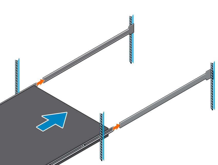
Z9432F-ON switch installation 196. Attach the outer rail to the front of the four-post rack. The rail clicks into place.
7. Repeat these steps for the second rail.
8. Slide the inner rails that are attached to the switch into the outer rails that are attached to the rails.
NOTE: Press the spring clip on each inner slide rail to allow the switch to slide into the outer rail.
20 Z9432F-ON switch installation9. Tighten the thumbscrews to secure the switch to the rack.
To remove the switch, press the rail spring clip and pull the inner rail and switch out of the outer rail and rack.
Z9432F-ON switch installation 21To remove the outer rails from the rack, press the blue plastic button on each outer rail.
Four-post L-bracket rail installation
Use these installation instructions for racks with threaded holes, 9.5 mm (.354 in) square holes, or 7.1 mm (.279) round holes.
Complete the switch installation in the following order:
1. Attach the L-brackets to the front of the switch.
2. Attach the inner rails to the switch.
3. Attach the outer rails to the rear of the four-post rack.
4. Slide the switch into the rack.
5. Secure the L-brackets to the front of the four-post rack.
NOTE: You need a user-supplied Phillips screwdriver to complete this installation.
22 Z9432F-ON switch installationNOTE: For the EIA 9.5 mm (.354 in) square-hole rack, insert the cage nuts into the rack holes before you secure the
L-brackets to the rack. The cage nuts ship with the brackets and rails.
To install the switch:
1. Remove the rails, L-brackets, and screws from the shipping container.
2. Attach an L-bracket to each side of the switch front using four M4 screws.
3. Separate the inner rail and the outer rail.
4. Attach the inner rail to the switch.
Line up the slot on the inner rail with the T-stud on the switch. Push back to lock the rail into place.
Secure the inner rail to the switch using two M4 screws.
Z9432F-ON switch installation 23Repeat this step to attach the second inner rail to the other side of the switch.
5. Attach the outer rail to the back of the four-post rack.
Align the outer rail peg to the back of the four-post rack.
Secure the outer rail to the back of the rack using two M4 screws for each rail.
Repeat this step to attach the second outer rail to the other side of the rack.
6. Slide the inner rails into the outer rails.
24 Z9432F-ON switch installation7. Attach the L-brackets to the front of the four-post rack.
Align the L-bracket holes to the holes at the front of the four-post rack.
Secure the L-brackets to the front of the rack using two M4 screws for each side.
Z9432F-ON switch installation 25To remove the switch, remove the four screws from the L-brackets at the front of the rack and slide the switch forward.
To remove the rack rails from the rack, first remove the switch from the rack. Then remove the four outer rails screws at the
back of the rack.
Optics installation
For a list of supported optics, see the specification sheets at www.dell.com/support or contact your Dell EMC Sales
representative.
WARNING: When working with optical fibers, follow all warning labels and always wear eye protection. Never
look directly into the end of a terminated or unterminated fiber or connector as it may cause eye damage.
CAUTION: Switches with fan airflow from the PSU to the I/O—reverse airflow—are subject to tighter
restrictions for power consumption on cables and optics that are used for 400 GbE ports. Reverse airflow
switches do not support high-power cables or optics. 400 GbE transceivers and active cables may exceed the
supported threshold.
CAUTION: To avoid damage to the switch, when you cable the ports, be sure not to interfere with the airflow
from the small vent holes above and below the ports.
CAUTION: ESD damage can occur if components are mishandled. Always wear an ESD-preventive wrist or heel
ground strap when handling the Z9432F-ON switch and components.
1. Position the optic to enter the port correctly.
The optic has a key that prevents it from being inserted incorrectly.
2. Insert the optic into the port until it gently snaps into place.
26 Z9432F-ON switch installationOptics removal
Remove an optic by pushing the tab on the optic and sliding the optic from the port.
When removing optics with direct attach cables (DACs) from the port, pull the release tab firmly and steadily. Before pulling
the release tab, you may need to gently push the optic into the port to ensure that it is seated properly. Do not jerk or tug
repeatedly on the tab.
Switch startup
Supply power to the Z9432F-ON switch after it is mounted in a rack or cabinet.
Dell Technologies recommends reinspecting your switch before powering it up. Verify the following:
● Optional: The equipment is properly secured to the rack and properly grounded.
● Optional: The equipment rack is properly mounted and grounded.
● The ambient temperature around the unit, which may be higher than the room temperature, is within the limits that are
specified for the Z9432F-ON switch.
● There is sufficient airflow around the unit.
● The input circuits are correctly sized for the loads and that you use sufficient overcurrent protection devices.
CAUTION: Do not start up the switch if a fan module is not installed.
CAUTION: ESD damage can occur if components are mishandled. Always wear an ESD-preventive wrist or heel
ground strap when handling the Z9432F-ON switch and components.
NOTE: A US AC or DC power cable is included for powering up an AC or DC power supply. You must order all other power
cables separately.
Start up sequence
When the switch powers up, the fans immediately come on at high speed. The fan speed slows as the switch continues to boot.
After switch placement
After you have securely installed and turned on the Z9432F-ON switch:
● For switch documentation and resources, see the Dell EMC Networking OS10 Info Hub.
● For OS10 Networking operating system documentation and resources, see the Dell EMC Networking OS10 Info Hub.
● For ONIE documentation and resources, see www.onie.org.
NOTE: If necessary, to upgrade your software or firmware images, go to the Drivers and Downloads page for your switch
at www.dell.com/support.
Switch replacement
The following steps describe removing and replacing a switch with an identical replacement switch. For further assistance when
replacing a switch, contact your Dell EMC support representative.
NOTE: Some steps do not apply if you are replacing a different switch or non-Dell EMC switch.
NOTE: ESD damage can occur when components are mishandled. Always wear an ESD-preventive wrist or heel ground
strap when handling the switch and accessories. After you remove the original packaging, place the switch and components
on an anti-static surface.
1. Back up the switch configuration to your back-up computer or laptop TFTP server.
OS10# copy config://startup.xml config://
2. Disconnect the power source.
Z9432F-ON switch installation 273. Label and remove all cables.
4. Remove the switch from the rack.
At the same time, press in the two side-release bars on the switch and slide the switch forward.
If you are using the fan trays or PSUs in the replacement switch, remove them from the switch.
5. Unpack the new switch.
6. Install the new switch in your rack or cabinet.
For detailed installation instructions, see Z9432F-ON switch installation.
If you are using the fan trays or PSUs from the removed switch, reinsert them in the replacement switch.
7. Connect all the cables.
8. Power on the switch.
For more information, see Switch start-up.
9. Establish a connection to the switch CLI.
10. Confirm that the software version of the replacement switch is the same as the previously installed switch.
show version
If the software versions do not match, upgrade the replacement switch software using the procedure included with the
firmware download.
11. Copy the backed-up switch configuration to the new switch.
copy tftp://hostip/filepath running-config
28 Z9432F-ON switch installation5
Power supplies
The Z9432F-ON switch ships with two AC or DC power supplies. The two power supplies have two air-flow directions—from
the I/O to the PSU and from the PSU to the I/O.
CAUTION: PSU and fan airflow directions must match. To avoid damage to the switch, do not mix normal and
reverse airflows in a single switch.
Two PSUs are required for full redundancy, but the switch can operate with a single PSU.
The PSUs are field replaceable. When running with full redundancy—two power supplies installed and running—you can remove
and replace one PSU without disrupting traffic.
CAUTION: To prevent electrical shock, ensure that the Z9432F-ON switch is grounded properly. If you do not
ground your equipment correctly, excessive emissions may result. Use a qualified electrician to ensure that the
power cables meet your local electrical requirements.
NOTE: Connect the power supply to the appropriate branch circuit protection as defined by your local electrical codes.
Verify that the remote power source complies with the switch input power specifications.
NOTE: If you use a single PSU, install a blank plate in the other PSU slot to ensure proper airflow for cooling. Use power
supply 2 (PSU2) as the blank plate slot. To install the blank plate, use a #1 Philips screw driver.
NOTE: ESD damage can occur if components are mishandled. Always wear an ESD-preventive wrist or heel ground strap
when handling the Z9432F-ON switch and components.
Topics:
• Components
• AC or DC power supply installation
• AC or DC power supply replacement
• DC power connections
Components
The following power supply options are available for the Z9432F-ON switch:
● AC or DC power supply with integrated fan
● AC or DC power supply with integrated reverse flow fan
NOTE: Redundant AC power requires high-line 200 VAC to 240 VAC. Using low-line 120 VAC does not provide redundancy
for the switch.
When facing the PSU-side of the switch, power supply 1 (PSU1) is on the left side of the switch; power supply 2 (PSU2) is on
the right side of the switch.
1. PSUs
The PSUs have an integrated fan, which you cannot replace individually; if the fan integrated in a PSU fails, you must replace
the entire PSU. You can replace the fan trays individually. For fan tray replacement procedures, see Fans.
Power supplies 29WARNING: Prevent exposure and contact with hazardous voltages. Do not attempt to operate this switch with
the safety cover removed.
CAUTION: Remove the power cable from the PSU before removing the PSU. Also, do not connect the power
cable before you insert the PSU in the switch.
NOTE: To comply with the GR-1089 Lightning Criteria for Equipment Interfacing with AC or DC Power Ports, use an
external surge protection device (SPD) at the AC or DC input of the router.
PSU LEDs
● Solid green—Input is OK.
● Flashing yellow—There is a fault with the PSU.
● Flashing green blink at 1 Hz—Switch is in a standby or CR state.
● Off—PSU is off.
AC or DC power supply installation
NOTE: The PSU slides into the slot smoothly. Do not force a PSU into a slot as this action may damage the PSU or the
switch.
NOTE: Ensure that you correctly install the PSU. When you install the PSU correctly, the power connector is on the left
side of the PSU.
NOTE: If you use a single PSU, install a blank plate in the other PSU slot to ensure proper airflow for cooling. If you are only
using one power supply, install the power supply in the first slot, PSU1. Install a blank plate in the second slot, PSU2.
1. Remove the PSU slot cover from the Z9432F-ON switch using a small #1 Phillips screwdriver.
2. Remove the PSU from the electro-static bag.
3. Insert the PSU into the switch PSU slot—insert the exposed PSU connector first.
The PSU slot is keyed so that you can only fully insert the PSU in one orientation. When you install the PSU correctly, it
snaps into place and is flushed with the back of the switch.
4. Plug in the appropriate AC 3-prongs cable from the switch PSU to the external power source.
5. Repeat steps 1–4 if you have a redundant PSU using the second PSU slot on the Z9432F-ON switch.
1. When facing the PSU-side of the switch, PSU1 is on the left side of the switch. PSU2 is on the right side of the switch.
NOTE: The Z9432F-ON switch starts up when you connect the cables between the power supply and the power
source.
30 Power suppliesAC or DC power supply replacement
CAUTION: Disconnect the power cable before uninstalling the power supplies. Also, disconnect all power cables
before servicing.
NOTE: The PSU slides into the slot smoothly. Do not force a PSU into a slot as this action may damage the PSU or the
Z9432F-ON switch.
NOTE: If a PSU fails, you must replace the entire unit. There are no field serviceable components in the PSU. To request a
hardware replacement, see www.dell.com/support/.
NOTE: If you use a single PSU, install a blank plate in the other PSU slot to ensure proper airflow for cooling. If you are only
using one power supply, install the power supply in the first slot, PSU1. Install a blank plate in the second slot, PSU2.
1. Disconnect the power cable from the PSU.
2. Use the grab handle to slide the PSU out of the power supply bay.
3. Use the grab handle on the replacement PSU to slide it into the power supply bay.
4. Attach the power cables to the replacement PSU.
NOTE: The switch powers up when the cables are connected between the power supply and the power source.
DC power connections
Each DC PSU comes with one DC cable. The cable ships in a separate plastic bag.
CAUTION: This product must be supplied by a DC power source rated -48 Vdc to -60 Vdc, 40 A minimum,
and Tma = 45-degree C minimum. The altitude of operation is 5000 m. The product must be supplied by a
UL-Listed DC power source that is separated from AC mains by double or reinforced insulation when the switch
is connected to DC power. For more information, contact your Dell sales representative.
NOTE: You need a user-supplied Philips screwdriver to complete this installation.
1. Wiring block
2. DC cable
3. PSU socket
1. Strip a one-half inch section of insulation from each of the power connector wires.
2. Insert each of the bare wire power connector lengths into the wiring block.
The blue wire is -48 V, the black wire is the positive return, and the yellow and green wire is the ground wire, 10 AWG
minimum.
Power supplies 313. Use a user-supplied flat-head screwdriver to tighten the screws that secures the bare wires into the wiring block.
4. Remove the tape and plastic cover, the two M4 screws and one M5 screw from the PSU socket. Keep all the removed parts.
5. Attach the blue wire and black wire to the PSU socket. Secure the wires with the two M4 screws.
NOTE: Attach the blue wire to the V- terminal. Attach the black wire to the V+ terminal.
6. Return the plastic cover back to the PSU socket.
7. Attach the yellow and green wire to the PSU GND. Secure the wire with the M5 screw.
32 Power suppliesTo uninstall the cable from the DC PSU, remove the plastic cover and unscrew the M4 and M5 screws. Pull the DC cable out
from the DC PSU socket.
Power supplies 336
Fans
The Z9432F-ON switch comes from the factory with seven fan modules that are installed in the switch. The fan modules, which
have integrated fans, are hot-swappable.
Besides the power supply modules, you can order and install fan modules separately.
The Z9432F-ON switch supports two airflow direction options. To avoid damage to the switch, do not mix airflow types in a
switch; you can use only a single airflow direction in a switch. If the airflow directions are mismatched, you must correct the
mismatched airflow direction.
CAUTION: Switches with fan airflow from the PSU to the I/O—reverse airflow—are subject to tighter
restrictions for power consumption on cables and optics that are used for 400 GbE ports. Reverse airflow
switches do not support high-power cables or optics. 400 GbE transceivers and active cables may exceed the
supported threshold.
● Airflow is from the I/O panel to the PSU—the red indicator is the normal airflow direction.
● Airflow is from the PSU to the I/O panel—the blue indicator is the reverse airflow direction.
NOTE: Fan and PSU airflow directions must match. Do not mix normal and reverse airflows in a single switch.
Environmental factors can decrease the amount of time that is required between fan replacements. Check the environmental
factors regularly. An increase in temperature or particulate matter in the air might affect performance—for example, new
equipment installation).
Topics:
• Components
• Fan module installation
• Fan module replacement
Components
The following are the Z9432F-ON switch fan components:
● Z9432F-ON switch fan module
● Z9432F-ON switch fan module—reverse flow
When facing the fan modules, fan slot 1 is on the left side of the switch. Fan slot seven is on the right side of the switch.
1. Fans
Fan LEDs
● Solid green—Fan function is normal.
● Flashing yellow—There is a fan fault.
● Off—Fan is off.
34 FansFan module installation
The fan modules in the Z9432F-ON switch are field replaceable.
CAUTION: DO NOT mix airflow directions. All fans must use the same airflow direction—reverse or normal. If
you mix the airflow direction, to avoid damage to the switch, you must correct the mixed airflow .
1. Take the fan module out of the shipping box.
2. Slide the module into the bay.
1. Fan module. When facing the fan modules, fan slot 1 is on the left side of the switch. Fan slot seven is on the right side of
the switch.
Fan module replacement
To request a hardware replacement, see www.dell.com/support/.
CAUTION: Complete the following steps within one minute or the switch temperature could rise above safe
thresholds and the switch could shut down:
1. Take the replacement fan module out of the shipping box.
2. Slide the installed fan module out of the bay.
3. Slide the replacement module into the bay.
Fans 357
Management ports
The Z9432F-ON switch provides three ports for management and one USB flash drive mount for file transfers.
NOTE: The output examples in this section are for reference only. Your output may vary.
Topics:
• RJ45 console port access
• Micro-USB Type-B console port access
RJ45 console port access
The management ports are on the I/O-side of the switch.
1. Out-of-band management port (top); RJ45 console port (bottom).
NOTE: When connecting the RJ45 console to the patch panel or terminal server using Cat5e or Cat6 Ethernet cables, the
maximum cable length is 100m. However, if the Ethernet cable is disconnected from the patch panel or terminal server but
connected to the RJ45 console, the maximum cable length is 6m. If the cable is longer than 6m when disconnected from
the panel or server, your switch may not boot.
NOTE: Ensure that any equipment that is attached to the serial port can support the required 115200 baud rate.
NOTE: If the serial port on your computer cannot accept a female DB-9 connector, use a DB-9 to USB adapter.
1. Install the provided RJ45 connector-side of the provided cable into the switch console port.
2. Install the DB-9 female-side of the provided copper cable into the serial port on your computer.
Or install the DB-9 cable into other data terminal equipment (DTE) server hardware.
3. Use the following settings to make the serial port connection:
● 115200 baud rate
● No parity
● Eight data bits
● One stop bit
● No flow control
Micro-USB Type-B console port access
The Micro-USB Type-B console port is on the I/O side of the switch.
NOTE: The Z9432F-ON uses switches use the Silicon Labs CP2102 USB Type-B chip. To find the correct USB Type-
B universal asynchronous receiver-transmitter (UART) driver, see https://www.silabs.com/products/development-tools/
software/usb-to-uart-bridge-vcp-drivers.
36 Management portsWhen you connect the micro-USB Type-B port, it becomes the primary connection and, while connected, all messages are sent
to the micro-USB-B port.
1. Power on the personal computer.
2. Connect the USB Type-A end of cable into an available USB port on the computer.
3. Connect the micro-USB Type-B end of cable into the micro-USB Type-B console port on the switch.
4. Power on the switch.
5. Install the necessary Silicon Labs drivers.
6. Open your terminal software emulation program to access the switch.
7. Confirm that the terminal settings on your terminal software emulation program are as follows:
● 115200-baud rate
● No parity
● Eight data bits
● One stop bit
● No flow control
Management ports 37You can also read