FOCUS 320 SBR Owner's Manual - Residential Factory Built Fireplace - RSF Fireplaces
←
→
Page content transcription
If your browser does not render page correctly, please read the page content below
Owner's Manual
 Residential Factory Built Fireplace

  Operation • Maintenance • Installation

FOCUS 320 SBR

       Keep these instructions for future use.

                 Industrial Chimney Company Inc.
       400 J.-F. Kennedy, St-Jerome, QC, Canada, J7Y 4B7
                    Telephone: (450) 565-6336
                          www.icc-rsf.com

                                                           RSF-IIF320SBR - 2020-02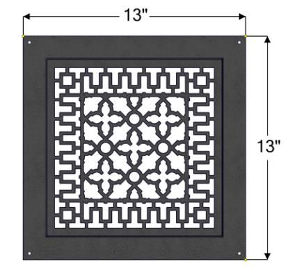
Dear Customer,
The FOCUS 320 SBR incorporate technology with elegance to give you a beautiful view of the
fire without compromising on heating efficiency or environmental quality.
We have designed your new FOCUS 320 SBR to be easy to install, operate and maintain. It is
in your best interest to become familiar with it. Study your manual to be sure that the installation
is correct, then follow the guidelines for operation and maintenance.
We at RSF Woodburning Fireplaces congratulate you on your choice of the FOCUS 320 SBR,
and are confident that you have purchased a fireplace that is simply, the best.
Sincerely,
RSF Woodburning Fireplaces Team
September 2019
TABLE OF CONTENTS
SAFETY FIRST 3 STANDOFFS INSTALLATION 15
SECURING THE FIREPLACE IN PLACE 16
DO'S AND DONT'S 3
OUTSIDE AIR DUCT 16
CREOSOTE: FORMATION AND REMOVAL 3
MANDATORY OPTIONS 16
GENERAL SPECIFICATIONS 4 CHIMNEY 17
CHIMNEY INSTALLATION 17
THE COMBUSTION CONTROL SYSTEM 4
OFFSET CHIMNEY 18
OPTIONS 4
CHASE ENCLOSURE 19
UNIT DIMENSIONS AND CLEARANCES 6
MASONRY CHIMNEY 20
OPERATION 8 FRAMING 21
COVERING THE FIREPLACE FACING 22
AIR CONTROLS 8 MANDATORY OPTIONS WITH THE CLEAN FACE 22
IMPROVING EFFICIENCY 8 HEARTH EXTENSION 22
IMPORTANCE OF DRAFT 8 BENEATH HEARTH EXTENSION 22
BURN TIME VS HEAT OUTPUT 8 MANTEL 22
FUEL 8 REFRACTORY BRICK INSTALLATION 23
FIRST FIRES 9 BAFFLE 23
LIGHTING 9
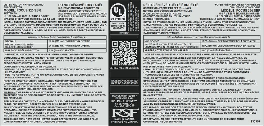
REFUELING 9 LISTING LABEL 24
TROUBLESHOOTING PROBLEMS 10
COMPLETE OPTIONS LIST 25
MAINTENANCE 10
CONFIGURED OPTIONS LIST 27
CHIMNEY CLEANING 10
REPLACEMENT PARTS 28
DISPOSAL OF ASHES 10
GENERAL CLEANING 11 LIMITED WARRANTY 29
GLASS CLEANING 11
PAINT 11
DOOR ADJUSTMENT 11
INSTALLATION 11
LOCATION 12
MOBILE HOME INSTALLATION 15
CEILING CLEARANCE 15
FOCUS 320 SBR Owner's Manual 2 RSF Woodburning Fireplaces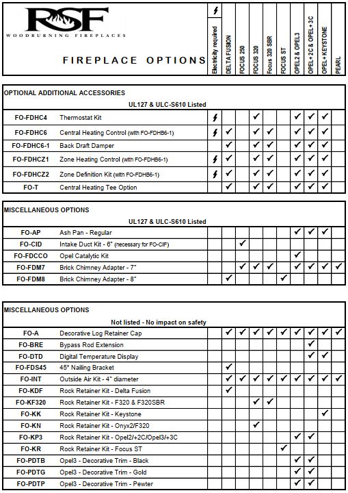
SAFETY FIRST
DO'S AND DONT'S
If this fireplace is not properly installed, a house fire could result. For your safety, follow the installation
directions. Contact your local authority having jurisdiction (such as municipal building department, fire
department, fire prevention bureau, etc.) regarding restrictions and installation requirements, and the need
to obtain a permit.
To ANYONE using this fireplace: these DO's and DONT's are for your safety.
1. DO read this instruction manual before lighting your first fire.
2. DO burn seasoned wood fuel or a combination of densified fuel logs and wood fuel.
3. DO operate the fireplace with the door fully closed. If the door is left partly open, gas and flame can be
drawn out of the fireplace opening, creating both fire and smoke hazards.
4. DO keep all combustible materials (furniture, firewood, etc.) at least 4' away from the front of the fireplace.
5. This fireplace needs periodic inspection and repair for proper operation. DO learn to properly use it and maintain
it.
6. Do have at least one smoke detector on each level of the house and at least one carbon monoxide detector.
7. To avoid glass breakage, DO NOT slam the fireplace door.
8. DO NOT ever use gasoline, gasoline-type lantern fuel, kerosene, charcoal lighter fluid or similar liquids to start
or freshen up a fire in this fireplace. Keep all such liquids well away from the fireplace while it is in use.
9. DO NOT overfire the fireplace. If you are unable to slow down the burn rate of the fire or if the chimney
connector behind the top louver glows red, you are overfiring the fireplace.
10. DO NOT use a fireplace grate or other products not specified for use with this fireplace.
11. The burn rate is set by the automatic air control at the factory. DO NOT tamper with the air control. DO NOT
install a flue damper that would allow you to reduce the chimney draft and thus slow the minimum burn rate.
12. To avoid damaging the fireplace, DO NOT operate it in a manner inconsistent with the operating instructions in
this manual.
13. DO NOT install an insert in this fireplace.
NOTE: We strongly recommend that our products be installed and serviced
by professionals who are certified by the National Fireplace Institute in the
U.S. or by Wood Energy Technology Transfer Inc. in Canada.
CREOSOTE: FORMATION AND REMOVAL
When wood is burned slowly, it produces tar and other organic vapors which combine with the expelled moisture
from the wood to form creosote. The creosote vapors can condense in the relatively cool chimney of a slow burning
fire. As a result, creosote residue accumulates on the flue lining. When ignited, this creosote makes an extremely
hot fire.
The chimney should be inspected periodically during the heating season to see if a creosote build-up has occurred.
The presence in a chimney of soot or creosote in excess of 1/8" (3mm) thick will indicate the need for immediate
cleaning, possible modification of burning procedures, and more frequent inspections.
❖ WARNING: USE SOLID FUEL ONLY. BURN DRY WOOD ONLY.
DO NOT BURN: DRIFTWOOD, TREATED WOOD, COAL, GARBAGE, OR PLASTIC.
FOCUS 320 SBR Owner's Manual 3 RSF Woodburning Fireplaces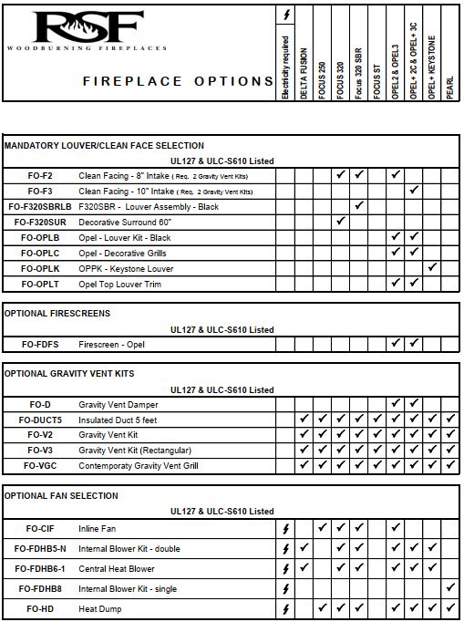
Do not use construction scraps (e.g. 2x4 or plywood scraps) as your only supply of fuel as you can overheat and
seriously damage the fireplace.
We do not recommend using wax fuel logs (e.g. Duraflame) in this fireplace because it will dirty the glass. If you
choose to use wax or densified firelogs, do not use more than one at a time and do not poke or stir the logs while
they are burning. Use only firelogs that have been evaluated for fireplace use. In Canada, they must meet the
requirements of ANSI/CAN/UL/ULC 2115, Processed Solid Fuel Firelogs and Firestarter. Refer to the firelog
warnings and caution markings on packaging prior to use.

GENERAL SPECIFICATIONS
The FOCUS 320 SBR is environmentally friendly and meets the 2020 United States Environmental Protection
Agency (EPA) particulate emission standard with crib wood at an emission rate of 1.4 grams per hour.
Using data from a crib wood EPA emission tests and using CSA B415.1-10 calculations, it has an efficiency of 66%.
This has been established using the higher heating value of the wood.
Under the best burning conditions and using CSA B415.1-10 calculations, it has an optimal efficiency of 75%. This
has been established using the lower heating value of the wood.
It has been shown to deliver heat ranging from 10 000 to 50 000 BTU/h with an average of 35 000 BTU/h. Please
refer to the "Improving efficiency", the "Importance of draft", the "Burn Time vs Heat Output" and the "Fuel" sections
to better understand the various factors that influence the efficiency and heat output of your fireplace.

THE COMBUSTION CONTROL SYSTEM

Since the door is sealed, all combustion air must come through the fireplace's draft control. The draft control is an
assembly that increases or reduces the amount of air permitted into the firebox. A bi-metallic coil in the air control
allows more air when the unit is cold, and less air when the unit is hot, guarding against overheating. The air control
is fully automatic; there is no user access to the air control.
Control the fire as you would any normal fireplace, using one or two logs at a time for a smaller fire, or more logs
for more heat. Remember: when the fireplace is hot, the automatic air control will reduce the combustion air inlet
since the bi-metallic coil will shut the air control damper part way.

OPTIONS

Louver Options
There are different ways you can finish your fireplace1. You can choose to install louvers (black blade style FO-
F320SBRLB) or no louvers at all2 (FO-F2).
If you choose to install your fireplace without any louvers, you MUST install the Clean Face Option (FO-F2) along
with two Gravity Vent Kits (FO-V2 or FO-V3). Gravity vent dampers CANNOT be installed on a Clean Face fireplace.
Furthermore, we recommend that you do not install any option requiring electricity or a thermal switch inside your
fireplace since it will be difficult to access those components after the fireplace facing is covered with non-
combustible materials. If you decide nevertheless to install electricity or a thermal switch in your Clean Face
fireplace, remember that you may eventually have to break through the non-combustible finishing to access the
electrical box or the thermal switch for servicing.
Gravity Vent Options
Gravity vent kits3 allow hot air to be ducted from the fireplace to a room above or on the same level as the fireplace.
Clean Face installations require two gravity vents for heat circulation.
Each gravity vent kit includes 5’ of insulated flexible ducting, a fireplace adapter, an outlet grill adapter, and a
decorative outlet grill.

1
  You can also refer to the configured option list on page 24.
2 Not allowed in a mobile home installation.
3 Not allowed in a mobile home installation.

FOCUS 320 SBR Owner's Manual                                     4                         RSF Woodburning Fireplaces
FO-V2 FO-VGC (grill only for FO-V2) FO-V3 Additional 5’ lenghts of insulated flexible ducting can be ordered with the part code FO-DUCT5. Nevertheless, gravity vents have a maximum length of 15’. Heating Options For increased air circulation and marginally more heat output, you can add the Circulating Internal Blower (FO- FDHB5-N) to your Louvered fireplace or the Inline Fan (FO-CIF) to your Clean Face fireplace. NOTE: The FOCUS 320 SBR is equipped with a floor shield to protect the floor under the fireplace. This floor shield is made of two parts: the front part is insulated; the back part is a single layered sheet metal. Both parts are screwed together and factory installed to cover the entire floor below the firebox. It must never be removed. Only when installing the Internal Blower Option can the floor shield be modified. Follow the internal blower installation instructions but before reinstalling the floor shield, remove the screw, slide the back part over the front part and screw them back together. If you ever remove the internal blower make sure to extend the shield again. To maximize the distribution of the heat generated by your fireplace throughout many rooms and different floors, consider the Central Heat Option4. With our Central Heat Blower (FO-FDHB6-1), you can use ducts to circulate the fireplace heat to one or many rooms. The Central Heat Control (FO-FDHC6) will enable automatic control of the Central Heat Blower via a wall thermostat and thermal switch. The Zone Heat Control (FO-FDHCZ1) along with Zone Damper Kits (FO-FDHCZ2) will provide the same features as the Central Heat Control but for more than one heating zone. If you wish to install the Central Heat Blower on a Clean Face fireplace, you will need the Central Heat T (FO-T) that will enable you to connect the central heat duct along with the left gravity vent on the fireplace. For a simple way to circulate a moderate amount of warm air from the fireplace to another room, we offer the Heat Dump Kit (FO-HD). It includes a 180 cfm blower and is most often used to provide supplemental heating to a basement room when the fireplace is on the main floor, but it can also be used to send the warm air to an adjacent room or upstairs. The duct maximum length is 8' for the FO-HD. General Options To simplify the installation of thin non-combustible materials such as ceramic tile or sliced brick, we have designed a rock retainer kit. It is not designed or required for full brick or stone. With a Louvered fireplace, you can choose to leave all the black metal completely exposed or completely covered with non-combustible material. Whether you have chosen a Louvered or Clean Face fireplace, the FO-KN kit will help you finish the facing of the fireplace as you wish. Thin materials can also be installed directly on the face of the fireplace using high temperature silicone as glue, without a rock retainer kit. Decorative andirons (FO-A) are also an optional feature. The decorative andirons are made of cast iron and are more aesthetically appealing than the basic ones included with the fireplace. The decorative andirons are also taller, which reduces the chance of logs rolling forward. NOTE: Many options require wiring and/or electricity for their installation. If there is any chance that any of these options will be installed in the future then suitable wiring should be run during framing. Otherwise, it will be difficult to install these options later. You can refer to page 25 for a list of options that require electricity. Detailed installation instructions are included in the box with each option. These can also be obtained from our Internet Web Site: www.icc-rsf.com. 4 Not allowed in a mobile home installation. FOCUS 320 SBR Owner's Manual 5 RSF Woodburning Fireplaces
❖WARNING: THIS FIREPLACE HAS NOT BEEN TESTED WITH A GAS LOG SET (UNVENTED OR VENTED).
TO REDUCE RISK OF FIRE OR INJURY, DO NOT INSTALL A GAS LOG SET (UNVENTED OR VENTED) INTO
THIS FIREPLACE. DO NOT INSTALL A GAS LOG LIGHTER BECAUSE THE HEAT PRODUCED BY THE
FIREPLACE WILL PERMANENTLY DAMAGE THE GAS LOG LIGHTER.

UNIT DIMENSIONS AND CLEARANCES

                       43"
                13 1/2" 13 1/2"

                                   8"
         4"
                                        24"

                     42"
                     47"

                                        4 1/4"
                                        6 1/2"
                                        5"
  39"

    16 3/4"                       18 1/2"

                                        5"
                                        4"
                    29 3/4"

  Figure 1 Unit Dimensions and Clearances

FOCUS 320 SBR Owner's Manual                     6                 RSF Woodburning Fireplaces
Table 1 Unit Dimensions and Clearances
A Distance of combustible material from side, back and top standoffs 0" (0,0 mm)
B Minimum distance from the side wall to the side of the firebox opening 12" (305 mm)
Minimum ceiling height: measured from the base of the fireplace sealed enclosure 7' (2,13 m)
C to the lowest point of the ceiling above the fireplace. Applies
both to the inside and outside of the fireplace enclosure. vented enclosure 6' (1,83 m)
Minimum chimney height: minimum total chimney height from fireplace top to below
D 12' (3,66 m)
the chimney rain cap – Refer to Table 3 on page 17 if elbows are present
Maximum chimney height: maximum total chimney height from fireplace top to below
E 40' (12,19 m)
the chimney rain cap
F Maximum chimney height supported by the fireplace 18' (5,49 m)
G Minimum depth of non-combustible hearth extension: from the front of the fireplace 20" (508 mm)
Minimum width of non-combustible hearth extension: total width, must be centered
H 42" (1,07 m)
on the firebox opening
I Minimum width of the spark guard 36" (914 mm)
J Maximum mantel shelf depth (see Table 2 for other mantel sizes) 12" (305 mm)
Minimum height of a combustible mantel shelf above the top of the firebox opening:
K to the bottom of the combustible mantel (refer to the "Installation: Mantel" section See Table 2
for particulars)
Table 2 Various Mantel Shelf Depths and Corresponding Installation Heights
Maximum Mantel Shelf Depth Minimum Installation Height
0" to 6" 20"
12" 26"
No combustible mantel shelf can be installed lower than 20" above the top of the firebox opening. A combustible
mantel shelf cannot be deeper than 12".
For any combustible mantel shelf depths between 6" and 12", you can calculate the minimum installation height.
For example:
• Mantel shelf depth to be installed: 9¼"
• So: (9.25 – 6) + 20 = 23.25 = 23¼"
• Thus, minimum installation height of a 9¼" mantel: 23¼" above the firebox opening
If the combustible mantel shelf has a cross-section with variable depth, it has to be installed so that its widest
part is not installed lower than the corresponding minimum installation height while making sure that the lowest
point of the mantel is not installed lower the minimum installation height corresponding to it depth.
Refer to the "Installation: Mantel" section for particulars.
FOCUS 320 SBR Owner's Manual 7 RSF Woodburning FireplacesOPERATION AIR CONTROLS Combustion Air Control The bi-metallic coil is a unique feature built into your fireplace. It serves as a fully automatic combustion air control. As the fireplace heats up, it will activate the bi-metallic coil. This will automatically begin to shut down the air entering the firebox, slowing the combustion process. This will save you wood, reduce emissions, improve efficiency, and prevent the fireplace from overheating and causing potential damage to the firebox. Outside Air Control The FOCUS 320 SBR is designed to use outside air for combustion. Because outside air is generally colder and denser it will help to start the fire. In some cases, fresh air will help compensate for negative pressure problems within the house; however, it will not prevent the fireplace from smoking in a severely depressurized house. We recommend always using outside air for combustion, but you may choose to use room air for combustion instead. You will find a sliding door behind the bottom louver and below the firebox. Push the sliding door towards the back to select outside air or pull it toward the front to select inside air as the combustion air. If the fireplace is installed in a mobile home, the outside air MUST be used as combustion air. IMPROVING EFFICIENCY The location of your fireplace will affect how efficiently it heats the home. Your fireplace should be located in part of the house you want to be the warmest. Trying to heat the main floor with a fireplace in the basement will generally overheat the basement and waste fuel. Certain RSF options offer the ability to move heat from the main floor to the basement. This allows you to efficiently heat your primary space while also heating the basement as a secondary space. The efficiency can also be influenced by various factors such as the draft in the chimney (refer to "Importance of draft" below), the amount of wood burning at any point (see "Burn Time vs Heat Output" below) and the quality of the wood (refer to "Fuel" below). All of these factors must be considered and optimized in order to recover the maximum heat from your fireplace. IMPORTANCE OF DRAFT Draft is the natural force which pulls air from the fireplace up the chimney. The strength of draft in your chimney depends on a variety of factors, including chimney height, nearby obstructions, altitude, etc. Excessive draft can result in a hotter fire than intended or reduced burn times as more air is pulled through the fireplace. It will also result in less heat recovery since the heat will not have as much time to radiate into the room before being sucked into the chimney. Weak draft can result in smoke entering the room and difficulty lighting or operating the fireplace. Weak draft is often incorrectly associated as a blockage in the air intake for the fireplace. Adding chimney height is the most common solution. See Table 3 for minimum chimney height recommendations. BURN TIME VS HEAT OUTPUT The faster your fireplace burns the more heat it will create; however, faster fires result in much more hot air flow up the chimney which means you are sacrificing efficiency. Fast burning fires (lots of air) go through much more wood than slow burning fires. Your fireplace burns at a fixed rate depending on the heat inside the firebox. It will burn quickly during light up and then gradually slow down to offer the best efficiency and emissions reduction. FUEL All modern high efficiency fireplaces and woodstoves are designed to burn best with seasoned cordwood. Seasoned wood can be defined as wood that has been cut, split and let dry under cover for a minimum of 6 months, preferably FOCUS 320 SBR Owner's Manual 8 RSF Woodburning Fireplaces
a year or more. Dry seasoned wood generally contains less than 20% moisture content. Attempting to burn fuel
with a high moisture content will be difficult and result in lower efficiency, increased creosote buildup and dark
deposits on the glass. It is possible to burn a very large amount of wood and get very little heat if the wood is wet.
The type of wood you select is also important. All types of wood give off more or less the same number of BTU’s
per pound. Since softer woods are less dense than hardwoods it is possible to put more weight of hardwood in the
firebox; in other words, all woodburning appliances will burn longer and more evenly with hardwoods. Never burn
scrap, garbage, treated wood or driftwood as they produce much more pollution and can corrode the firebox and
chimney as well. Burning large amounts of paper, cardboard, mill ends, or construction waste can easily over fire
and damage the fireplace or even ignite a chimney fire if the flue is dirty.

FIRST FIRES

You will experience a slow start-up during the first few fires. The refractory bricks lining the firebox contain moisture
from manufacturing and require a few hot fires to evaporate the moisture. While there is still moisture in the bricks,
they will be black with smoke deposits. When the moisture has dissipated, the bricks will turn white. Unlike cast iron
stoves, there is no need to cure the fireplace itself by starting with small fires and progressively larger ones. Feel
free to light a large fire from the very start.
You will experience a slight odor during the first few fires. This odor comes from curing paint and oil burning off the
metal. The odor may be strong enough to set off your smoke detector. Open the doors and windows to allow the
room to properly ventilate.

LIGHTING

Start by laying your fire starter and kindling. Traditional fire starter is crumpled newspaper; make sure to use enough
to light the kindling (5-6 pieces should do). Next lay 3 or 4 layers of kindling crisscrossed over the newspaper. Using
plenty of kindling ensures that the chimney will heat up quickly and establish a strong draft, never use any
flammable liquids. Light the paper and close the door most of the way, but don’t shut it completely, keep it about
1" from being completely closed. If the door is positioned correctly you will see air rushing into the fireplace, this will
help the lighting process.
Once the kindling is lit and sustaining fire, you can add some small pieces of seasoned cordwood. Use the andirons
in front to help position the cordwood so as not to flatten and smother the fire you’ve just created. Always add at
least 3 pieces of cordwood. Position your cordwood in a manner that the fire will hit several pieces as it rises and
has air gaps to flow through. Continue to leave the door slightly open until the cordwood is lit, about 3-5 minutes.
Close the door completely when the fire is established.
During light up, it is normal for the glass to accumulate some soot and become dark. As the fireplace heats up, this
should burn off and reveal a nice view of the fire.
❖ WARNING: DO NOT USE A GRATE OR ELEVATE THE FIRE.

❖ WARNING: MAKE SURE TO KEEP THE FIRE BEHIND THE ANDIRONS. REPOSITION THE LOGS IF THEY
FALL AGAINST THE GLASS.

REFUELING

Have your next wood load ready when you open the door. The temperature in the firebox will decrease dramatically
while the door is open, so decreasing the amount of time the door is open will allow the firebox to remain hotter.
Nevertheless, do not rush.
Turn off the central heat and/or internal blowers, if installed. The blowers may cause smoke to spill out of the
fireplace if they are running.
The door should be opened slowly to keep smoke from spilling into your room. If you have a problem with smoke
spillage, check to see that all kitchen and bathroom fans have been shut off. They can cause negative pressure in
the house which pulls smoke out of the fireplace.
Take the time to poke and stir the unburnt wood that is left in the firebox. This will help revive the fire. Place the
new logs in the firebox. Try to maintain a clear path in front of the pilot, which is the metal tube centered between
the two andiron posts. The pilot brings an influx of air close to the coals that will help to keep the fire going. Once
the new wood has been loaded, keep the door slightly ajar for about 3-10 minutes to get the fire going depending

FOCUS 320 SBR Owner's Manual                                9                                 RSF Woodburning Fireplaces
on how well seasoned your cordwood is and how much coals were left in the firebox. Once the new wood is well lit,
close the door.
Wait at least 15 minutes after shutting the door after reloading before turning any blowers back on. This ensures
that heat will built up in the firebox before being cooled by the blower and ensures that your fireplace will continue
on burning as clean as it can.

TROUBLESHOOTING PROBLEMS

If smoke comes into the house when the door is opened:
•   You may have opened the door too quickly and created a suction of air into the room, this can be avoided by
    opening the door more slowly.
•   Ensure your chimney is clean and your chimney cap is not plugged. Chimney caps with screens are more likely
    to become clogged with creosote buildup.
•   Make sure you have adequate chimney height for your system. Refer to the Chimney section of this booklet
    and make sure to take altitude, and number of elbows into consideration.
•   If you have purchased the central heat kit option or the circulating internal blower, make sure the blower is off
    before opening the door.
•   Check to see if other fans in the home are running, particularly a kitchen range hood, or bathroom exhaust fan.
    This can affect the pressure in the home.
•   Try opening a window near the fireplace a little, this will equalize the pressure in the home and should correct
    a draft problem. Once proper draft is established the window can be closed.
•   Make sure you’ve used enough kindling to establish a hot fire quickly. The most likely time that smoke will enter
    the home is during the lighting process.
If your fireplace burns excessively fast, seemingly uncontrollably:
•   Check all door seals and gaskets to ensure that air is not leaking into the firebox. See “Door Adjustment” for
    details of how to verify the tightness of the door.
•   Inspect the secondary air tubes in the top of the fireplace to ensure they are in good condition. An unwanted
    hole in the secondary air tubes can bring additional unwanted air into the fireplace.

MAINTENANCE
CHIMNEY CLEANING

Check the chimney for creosote buildup every week or so until experience shows how often you need to clean it. A
buildup of 1/8" (3 mm) or more should be cleaned before more creosote accumulates. Close the fireplace door(s)
prior to sweeping. Use an 7" round brush.
We do not recommend moving or removing the baffle for chimney sweeping. The top part of the baffle is a metal
plate that can be easily vacuumed after sweeping the chimney. Be careful not to get too close to the sides and back
of the firebox with the vaccum nozzle. The soft white insulation can be easily torn and swallowed.
Nevertherless, if you prefer to remove the baffle, you will have to remove both side refractory bricks (see the
"Refractory Brick Installation" section for detailed instructions), then remove the front secondary air tube (remove
the cutter-pin on the left) and then the baffle (see "Baffle" section for detailed instructions). Make sure to reinstall
everything correctly after cleaning.

DISPOSAL OF ASHES

Remove the ashes before they become too deep, i.e., before you have a spillage problem when you open the door.
The ashes should be placed in a metal container with a tight-fitting lid. The closed container of ashes should be
placed on a non-combustible floor or on the ground, well away from all combustible materials pending final disposal.
If the ashes are disposed of by burial, or otherwise locally dispersed, they should be retained in the closed container
until all cinders have thoroughly cooled.

FOCUS 320 SBR Owner's Manual                              10                               RSF Woodburning Fireplaces
GENERAL CLEANING The high heat paint can be cleaned with a soft damp cloth. Use a mild detergent and water. Do not use abrasive cleaners. GLASS CLEANING In a controlled combustion firebox, temperatures are not always high enough to keep the glass perfectly clean. A good hot fire once a day usually cleans off most of the deposits that have accumulated. Remember: the drier the wood and the hotter the fire, the cleaner the glass. A word of caution: although heat will not break the glass, impact can. Be careful not to hit the glass. ❖ WARNING: NEVER CLEAN THE GLASS WITH AN ABRASIVE CLEANER. USE ONLY A CLEANER RECOMMENDED BY YOUR DEALER. NEVER CLEAN THE GLASS WHILE IT IS HOT, A SERIOUS BURN CAN RESULT. THERE ARE A NUMBER OF EXCELLENT WOOD STOVE GLASS CLEANERS AVAILABLE WHICH ARE FAR SUPERIOR TO REGULAR GLASS AND OVEN CLEANERS FOR WOOD STOVE APPLICATIONS. PAINT ❖ WARNING: AVOID SPRAYING CERAMIC GLASS CLEANER OR OTHER CLEANERS ON THE PAINT OF THE FIREPLACE. THEY MAY REMOVE THE PAINT AND MAKE TOUCHUPS DIFFICULT. You can touch up the face of your fireplace with Stove Bright Metallic Black high temperature paint which is available at most fireplaces dealers. Follow the directions outlined on the spray can. DO NOT attempt to paint the fireplace while it is still warm. Keep the spray can away from any source of heat or open flame. Ensure that there is adequate ventilation in the room from the time you start painting until the paint is dry. Stove Bright is available in a wide range of colors if you want to change the color of your fireplace. We recommend that you take the time to protect or remove any item that you do not want to paint such as: the door glass, the fireplace surroundings, etc. The glass can be removed from the door but you will have to replace the gasket. DOOR ADJUSTMENT To check for a proper door seal, insert a sheet of paper between the door and the front of the fireplace and latch the door. Pull gently but firmly on the sheet of paper. If the paper either tears or is hard to retrieve, the adjustment is correct. Repeat this procedure along all sides of the door. The most important factor for controlling the burn rate of your fireplace is a good seal on the door gasket. If the door gasket is worn or damaged to the point where the seal is not adequate as described above, then remove and replace the gasket. Replacement kits are available from your RSF dealer. The door latch is progressive, the more your turn the handle the tighter the seal on the right side of the door. Beware not to always over tighten the door latch; this will result in premature failure of the door gasket or cause undue stress on the door handle. If needed, the hinges can be adjusted to improve the alignment of the door latch with respect to the hole in the fireplace facing, and for easy installation/removal of the door. NOTE: An improperly adjusted door seal can have a significant effect on the performance and durability of the fireplace. A poorly adjusted door can result in reduced efficiency, over firing, excessive wood consumption and premature fireplace failure. INSTALLATION Check with your local authority having jurisdiction (such as municipal building department, fire department, fire prevention bureau, etc.) regarding restrictions and installation requirements, and the need to obtain a permit. NOTE: We recommend that you remove the door until after all finishing work is completed around the fireplace. This will reduce the possibility of scratches, vandalism, or damage to the finish caused by gypsum dust, muriatic acid, plaster, cement, paint or any other harmful spray or liquid. FOCUS 320 SBR Owner's Manual 11 RSF Woodburning Fireplaces
LOCATION

Your FOCUS 320 SBR fireplace may be installed in many different ways (see Figure 2) without any special floor
reinforcement. We recommend that you take the time to plan your entire installation (fireplace, chimney, and
options) before beginning the actual installation (refer to Figure 3 and Figure 4).
Dimensions of the fireplace along with clearances are shown in Figure 1 and Table 1.
❖ WARNING: IF THIS FIREPLACE IS NOT PROPERLY INSTALLED, A HOUSE FIRE CAN RESULT. FOR
YOUR SAFETY, FOLLOW THE INSTALLATION INSTRUCTIONS AND CLEARANCES. DO NOT PACK
REQUIRED AIR SPACES WITH INSULATION OR OTHER MATERIALS.

1. Note the location of roof and floor joists. Try to choose a location that does not require cutting them.
2. If possible, run the chimney up through the inside of the house. If it must be run outside, it should be enclosed
   in an insulated enclosure (see "Installation: Chase Enclosure"). Remember, a cold chimney causes poor draft.

                                                                                             22"        64"

          44 1/4"

                                                                                             45"
              45"        24"
                                                                                             90"

 The framing dimensions are larger than required for ease of installation. Examples shown here are for a Louvered
 fireplace. An extra 12" is required on the left of the fireplace of a Clean Face fireplace to connect the intake air
 duct. The Heat Dump Option will also require an extra 12" on the selected side. Additional space, dependent on
 your desired installation, is also required on top and maybe on one side of the fireplace for the Central Heat
 Option
 Figure 2 Framing Examples for a Louvered Fireplace

FOCUS 320 SBR Owner's Manual                             12                               RSF Woodburning Fireplaces
Rain Cap
Storm Collar
Flashing*
Flashing
And Roof Radiation Shield
Radiation Shield with a
Storm Collar in the Attic
Radiation Shield
Ceiling
Hearth Extension and
Beneath Hearth Extension
(refer to text for particulars)
No combustible material over the
fireplace facing (grayed area,
refer to text for particulars)
Electrical Knock-outs
(on both sides of the fireplace)
Cold air trap (optional)
Outside Air Inlet (refer to text for particulars)
*Refer to text to determine the appropriate flashing
Figure 3 Louvered FOCUS 320SBR General Installation
FOCUS 320 SBR Owner's Manual 13 RSF Woodburning FireplacesRain Cap
Storm Collar
Flashing*
Flashing
And Roof Radiation Shield
Radiation Shield with a
Storm Collar in the Attic
Radiation Shield
Ceiling
Gravity Vent
Gravity Vent Option
Option (using
FO-V2
(using flexible insulated
flexible insulated ducting
ducting
provided by provided byTwo
ICC only): ICC
only): gravity
Two FO-V2's are
vents are
MANDATORY
MANDATORY with Clean
with the
Clean Facing
Facing(shown
(shownhere)
here)
Intake Grill part of Clean
Facing Option FO-F2
Obstruction plates part of
Clean Facing Option FO-F2
Hearth Extension and
Beneath Hearth Extension
(refer to text for particulars)
No combustible material over the
fireplace facing (grayed area,
refer to text for particulars)
Electrical Knock-outs
(on both sides of the fireplace)
Cold air trap (optional)
Outside Air Inlet (refer to text for particulars)
*Refer to text to determine the appropriate flashing
Figure 4 Clean Face Fireplace General Installation
FOCUS 320 SBR Owner's Manual 14 RSF Woodburning FireplacesMOBILE HOME INSTALLATION The installation of your fireplace is the same whether you install it in a regular home or in a mobile home. Nevertheless, you MUST comply with the following restrictions: 1. You MUST use a vented roof flashing. 2. You CANNOT install gravity vents. 3. You CANNOT install the central heating system. 4. You MUST use outside air as combustion air. ❖ WARNING: IF YOU PLAN ON INSTALLING YOUR CHIMNEY WITH AN OFFSET THROUGH THE WALL OF THE MOBILE HOME, VERIFY WITH THE AUTHORITIES HAVING JUSRISDICTION REGARDING THE OBLIGATION OF ENCLOSING THE CHIMNEY ON THE OUTSIDE OF THE MOBILE HOME. ❖ WARNING: DO NOT INSTALL IN SLEEPING ROOMS. Make sure to provide access openings to the fireplace and chimney enclosures. These access openings must be covered on a regular basis but must be easily opened to allow inspection of the installation and clearances after any move of the mobile home. Before using the fireplace, make sure that nothing is blocking the outside air inlet to freely allow outside air into the fireplace. Review tips provided in the "Troubleshooting Problems" section on page 9 regarding potential issues with household fans and depressurized homes. Be aware that burning wood generates carbon monoxide; make sure it does not accumulate inside the mobile home. Be also aware that depending on your smoke detector location with respect to the fireplace, your smoke detector may give you false alarms when the fireplace is being used. Be careful, if you ever decide to renovate around the fireplace. Clearances around the fireplace and the chimney MUST always be respected. A radiation shield must be installed, as usual, at each floor where the chimney passes through. The ICC part is long enough to extend to the outermost plane of the roof, which it must also protect. ❖ CAUTION: THE STRUCTURAL INTEGRITY OF THE MANUFACTURED HOME FLOOR, WALLS AND CEILING/ROOF MUST BE MAINTAINED. CEILING CLEARANCE Ceiling clearance is the distance from the base of the fireplace to the ceiling. If you vent the fireplace enclosure, you can then have a lower ceiling clearance as specified in Table 1 (C) for a vented enclosure. For a vented enclosure, you MUST install regular venting 3"x10" grilles or larger into holes cut within 1' of both the floor and the ceiling, to allow room air to circulate through the fireplace enclosure and reduce heat buildup. These venting grilles may be placed vertically or horizontally. Under no circumstances should the distance between the ceiling firestop and the base fireplace be less than the dimension specified in Table 1 (C). STANDOFFS INSTALLATION Before you begin installing your fireplace, you MUST install the standoffs provided on both sides of the fireplace and on the top. Please refer to Figure 5 to position them adequately. These standoffs provide the appropriate clearances for combustible wall covering and combustible framing around the fireplace. Do respect these clearances. Aligning the front edge of the return on all three standoffs with the facing of the fireplace will provide a guide for the front face of the wall covering to align with the front face of the fireplace. The top standoff MUST be screwed centered to the top of the fireplace casing using the self-tapping screws provided. The side standoffs MUST be screwed to both sides of the fireplace casing using the self-tapping screws provided. FOCUS 320 SBR Owner's Manual 15 RSF Woodburning Fireplaces
Once the standoffs are in place, make sure to seal the ¼"
gap between the fireplace and the standoffs with silicone
sealant. DO NOT fill the gap behind the sealant with
insulation or any other material.

SECURING THE FIREPLACE IN PLACE

The fireplace MUST be attached to the floor.
Using the four small brackets that were securing the
fireplace to the crate, attach the casing or base of the
fireplace to the floor. Position the brackets all around the
fireplace in the same fashion as they were on the crate. If
possible, try to have at least one of the brackets screwed
into the floor joists with 2" wood screws.

OUTSIDE AIR DUCT

After the fireplace is correctly positioned, connect the
outside air inlet to the fireplace.
Use an insulated aluminium flexible duct rated at over
200° F. The duct should not exceed 12' vertical rise above
the base of the unit. We suggest using the 4" RSF outside
air kit (FO-INT).
The air inlet should always be at least 5’ lower than
the chimney rain cap and must never terminate in attic            Figure 5 Standoffs Installation
spaces.
 A 4" diameter duct can be used if the total duct run is less than 25'. For longer runs, use 5" diameter duct. Both 4"
and 5" connecting sleeves are provided with the
                                                                Above Floor                            Below Floor
fireplace.
                                                                     Example                                           Example
                                                                                       re F

1. Find a convenient location for the insulated flexible
                                                                                             e

                                                                                                             re F
                                                                                                                   e
                                                                                     Fi RS
                                                                                           ac

                                                                                                           Fi RS
                                                                                                                 ac
                                                                                         pl

                                                                                                               pl
   duct and outside air inlet. The outside air inlet can
   be above or below floor level (see Figure 6).
2.    Make a 4 ¼" (5 ¼" if using a 5" diameter duct) hole
     in the outside wall of the house. Push the outside
     air inlet in from the outside. Seal the joint between
     the air inlet and the outside wall with an
     appropriate sealant.
                                                                                                 2" Aluminium             Outside Air
3.    Place the insulated flexible duct over the round                                            Duct Tape               Inlet
     sleeve on the outside air inlet. At both ends,
                                                                           re F
                                                                                 e

     carefully pull back the insulation and plastic cover,
                                                                         Fi RS
                                                                               ac
                                                                             pl

     exposing the flexible duct. Then at each end,
     attach the duct with metal screws to the air inlet
     and to the fireplace connecting sleeve. Carefully            Insulated Flexible Air Duct
     push the insulation and cover back over the duct.
     Tape the plastic cover in place with 2" aluminium                                      Outside Wall
     duct tape.
                                                               Figure 6 Outside Air Connection and Installation
You can make a cold air trap by looping the outside air        Example
duct as shown in Figure 3 and Figure 4.
❖ CAUTION: WHEN RUNNING THE DUCT AROUND CORNERS, BE SURE TO PREVENT CRIMPING THE
DUCT IN A WAY THAT WOULD RESTRICT THE COMBUSTION AIR FLOW.

MANDATORY OPTIONS

Do not forget to install the louvers (FO-F320SBRLB) or the Clean Face Option (FO-F2) along with the two required
Gravity Vent Kits (FO-V2 or FO-V3).

FOCUS 320 SBR Owner's Manual                                 16                                        RSF Woodburning Fireplaces
CHIMNEY
This fireplace is certified for use with 7" ICC Model EXCEL chimney only. Please refer to Table 1 (D-E) for the
minimum and maximum chimney height permitted with your fireplace.
We recommend that the minimum height be increased by approximately 6" for every 1000' elevation above sea
level. Every 15°, 30° or 45° offset (one pair of elbows) also increases the minimum height. 45° elbows are not
allowed in the USA. See Table 3 for more precise recommended flue heights.
For example, if you are living 6015' above sea level, your chimney should terminate at least 15' from the top of the
fireplace if it is a straight chimney or at least 18'6" if one 30° offset is used as shown in Table 3.
Table 3 Minimum Recommended Flue Heights
Number Of Offset
Elevation (ft) Straight
1 x 15° 2 x 15° 1 x 30° 2 x 30° 1 x 45° 2 x 45°
Chimney
Minimum
0 - 1000 13’ 14’ 15’ 18’ 16’ 20’
12’
1001 - 2000 12’6” 13’6” 14’6” 15’6” 19’ 16’6” 20’
2001 - 3000 13’ 14’ 15’ 16’ 19’6” 17’ 21’6”
3001 - 4000 13’6” 14’6” 15’6” 17’ 20’ 18’ 22’6”
4001 - 5000 14’ 15’ 16’ 17’6” 21’ 18’6” 23’
5001 - 6000 14’6” 15’6” 17’ 18’ 21’6” 19’ 24’
6001 - 7000 15’ 16’ 17’6” 18’6” 22’ 20’ 24’6”
7001 - 8000 15’6” 16’6” 18’ 19’ 23’ 20’6” 25’6”
8001 - 9000 16’ 17’ 18’6” 20’ 24’ 21’ 26’6”
9001 - 10000 16’6” 17’6” 19’ 20’6” 24’6” 22’ 27’
Flue height is measured from the top of the fireplace to the top of the chimney before installing the rain cap.
If you have two different offsets (two pairs of different elbows), simply use the column for two offsets of the
biggest pair of elbows at your elevation to get your Minimum Flue Height.
CHIMNEY INSTALLATION
Make sure to read the EXCEL Chimney installation manual concerning requirements for supports, bracing, anchors,
etc. The EXCEL Chimney manual is available at your RSF dealer or on our web site: www.icc-rsf.com. Refer to
Table 1 (F) for the maximum chimney height that can be supported by the top of the fireplace.
❖ WARNING: THE CLEARANCE BETWEEN THE CHIMNEY AND COMBUSTIBLE MATERIAL MUST BE 2"
OR MORE. DO NOT FILL THIS AREA WITH INSULATION.
1. Cut and frame the required holes in the floor(s), ceiling(s) and roof where the chimney will pass through. The
rough opening in the framing is 13" square (the opening can be slightly bigger, but NEVER smaller).
2. From below, install a radiation shield in each floor through which the chimney passes. At the attic level, install
a radiation shield and a storm collar as shown in Figure 7.
❖ WARNING: A RADIATION SHIELD MUST BE INSTALLED AT EACH FLOOR WHERE THE CHIMNEY
PASSES THROUGH.
If you have a cathedral ceiling, consider using our radiation shield for cathedral ceiling (XM-7ERSC).
FOCUS 320 SBR Owner's Manual 17 RSF Woodburning Fireplaces3. Place the first length of chimney on the fireplace.
Secure the chimney length to the fireplace with
the three screws provided. Assemble the rest of
the chimney.
The chimney must extend at least 3' above its
point of contact with the roof and at least 2' higher
than any wall, roof, or building within 10' of it. If
the chimney is higher than 5' above the roof, it
must be secured using a roof brace.
4. At the roof, install a roof radiation shield (XM-
7ERRS). The roof radiation shield must be
installed so it extends 1" above the roof line.
5. Put the roof flashing into place.
• If the chimney is enclosed to the roof: use
a vented flashing .
• If the chimney is not enclosed to the roof:
use a regular flashing.
6. Seal the joint between the roof and the flashing
with roofing tar. For sloping roofs, place the
flashing under the upper shingles and on top of
the lower shingles. Nail the flashing to the roof
using roofing nails.
7. Place the storm collar over the chimney and
* Refer to the text to determine the appropriate flashing
flashing. Seal it around the chimney with silicone
sealer (DO NOT use roofing tar). Figure 7 General Chimney Installation
8. Fit the rain cap on the chimney. Secure it tightly
in place.
OFFSET CHIMNEY
An elbow may be installed directly on top of the fireplace if required. See the detailed offset charts in the EXCEL
chimney installation manual. Use the offset option if you need to clear a joist or pass around a cupboard. See Figure
8 and Figure 9 for examples.
• Maximum offset angle:
• In USA: 30° • In Canada: 45°
• Maximum number of elbows: four, resulting in two offsets and returns.
Install the fireplace and chimney as described earlier. When you require an elbow, proceed as follows:
1. Install the required elbow. Turn it in the desired direction, and fasten it to the chimney length with the three
metal screws provided at the joints.
2. Install enough lengths to obtain the desired offset. Secure each joint with three metal screws. Refer to the offset
charts provided with the EXCEL chimney installation manual for exact offset dimensions.
3. Use another elbow to return the chimney to the vertical direction.
4. Install a wall support, or an offset support above each offset to support the weight of the chimney (elbows are
not designed to support the chimney above an offset).
FOCUS 320 SBR Owner's Manual 18 RSF Woodburning Fireplaces**
* Refer to the text to determine the appropriate flashing
** See particulars under "Through the Wall Offset" section
Figure 8 Offset Chimney Installation Example Figure 9 Offset Chimney Through a Wall Example
Through the Wall Offset
You can also go through the wall at an angle starting directly at the fireplace as depicted in Figure 9. An angled wall
insulated radiation shield (XM-7EWRSI30 or XM-7EWRSI45) must be used wherever the chimney passed through
an exterior wall. Make sure you have enough ceiling height. If not, you might want to consider installing the fireplace
in an outside chase.
If the chimney is enclosed once outside of the house, do not install the outside plate of the angled wall
insulated radiation shield.
Refer to the angled wall insulated radiation shield installation sheets for more detailed installations instructions.
CHASE ENCLOSURE
If the chimney runs up the outside of the house, we recommend that it be enclosed in a chase structure. The chase
should be constructed in such a way that it is an extension of the home (see Figure 10). It should be well insulated
between the footings and the floor of the home to prevent heat loss. If the climate in your area is mild, insulate the
chase at least to the first firestop. If the climate in your area is very cold, insulate the chase to the top to keep the
chimney warmer, increase the draft, and reduce creosote buildup. We also recommend insulating the ceiling of the
chase just as if it were in the attic space. This will prevent cold air from dropping down through the chase and into
the room where the fireplace is installed (see Figure 10).
Some local codes require that the walls be insulated, vapor sealed and sheathed with a fire rated gypsum board
(see Figure 10). We strongly recommend this procedure for all installations to prevent cold drafts from originating
in the fireplace enclosure. If you follow this procedure, we recommend that you do not insulate the wall above the
front of the fireplace.
FOCUS 320 SBR Owner's Manual 19 RSF Woodburning Fireplaces REMEMBER: Check local codes concerning installation
requirements and restrictions in your area.
MASONRY CHIMNEY
Installing your fireplace with a masonry chimney still
requires using EXCEL chimney from the top of the
fireplace to where it will connect to a listed liner that will
run up inside the masonry chimney (see Figure 11).
The stainless-steel liner should be fitted inside the clay
liner all the way to the top of the masonry chimney. It is not
meant to replace the clay liner. You can use either the
EXCEL liner or any other listed liner to ULC-S635, ULC-
S640 or UL-1777.
Special care is to be taken to make sure that you have a
good solid connection between the EXCEL chimney and
the liner. A masonry adaptor (FO-FDM7) was designed
specifically for that purpose and is available from your RSF
dealer. It will attach to the liner with 3 stainless steel rivets
(provided) and to the EXCEL chimney with 3 screws
(provided).
After mortaring in place, the connection between the
EXCEL chimney and the liner should not be visible in order
to isolate the heat released through the liner from the
fireplace enclosure.
As depicted in Figure 11, you must install at least one 18"
length of EXCEL chimney after the EXCEL chimney
elbow. The uppermost part of the EXCEL chimney - where
it enters the masonry chimney - must be a minimum of 12" * Refer to the text to determine the appropriate flashing
from the ceiling. Figure 10 Chimney Installed with a Chase
NOTE: If the ceiling is high enough, you can install one Enclosure Example
or more EXCEL chimney lengths directly on the fireplace
before the elbow.
If you use a flexible liner, make sure to be careful when cleaning to ensure that the stainless-steel flexible liner is
not dislodged in any way.
Using an Existing Masonry Chimney
❖ WARNING: IF YOU ARE CONSIDERING USING AN EXISTING CHIMNEY, IT MUST FIRST BE
THOROUGHLY INSPECTED BY AN AUTHORITY HAVING JURISDICTION TO DETERMINE THE FOLLOWING:
• The masonry chimney is well constructed and fully lined, in accordance with Local Building Codes and
the National Building Code of Canada (NBC) or National Fire Protection Association chimney standard
(NFPA 211).
• It has been thoroughly cleaned of any soot or creosote residue and inspected to determine that it is in
good working condition.
• There is no insulation of any type in contact with the masonry chimney and there is no insulation stuffed
anywhere in the chimney.
• All the necessary clearances around the masonry chimney, along the complete run of the chimney, are
respected as per NBC or NFPA 211. If the masonry chimney is enclosed in drywall, openings will
probably be required in order to verify clearances at all points.
• The masonry chimney will only be used for the fireplace and no other appliance.
FOCUS 320 SBR Owner's Manual 20 RSF Woodburning FireplacesIf major repairs are required to
meet the above conditions, a new EXCEL liner or other listed liner to Clearances as per
chimney should be constructed. ULC-S635, ULC-S640 or UL-1777 NBC or NFPA 211
To make the hole through the
masonry chimney and make the Metal
12" min. to Firestop
connection to the fireplace, we
combustible ceiling Mortar
recommend that you follow these
steps:
EXCEL chimney
1. Sight-in and mark the outline lenght: 18" min. Liner
of where the EXCEL chimney Elbow
EXCEL chimney
will penetrate the masonry elbow Mortar
chimney.
2. Using a large (¾" - 2") Masonry Adaptor
masonry drill bit, drill a hole FO-FDM7
re F
e
Fi RS
ac
exactly in the center of the
pl
oval outline. With a masonry
hammer and drill, slowly
enlarge the hole to the size
required. Remember to work Figure 11 Connection to a Masonry Chimney
from the center out. Be
especially careful with the clay liner behind the brick because three sides of it must stay in place.
3. Bring the stainless-steel liner down from the top of the chimney.
If you are using a rigid liner you will need enough room to secure an elbow to it with at least two screws.
If it is difficult to install rigid stainless-steel liner in the existing masonry chimney or for a masonry chimney with
less than 10"x10" inside, a listed stainless-steel flexible liner can be used along with a flexible/rigid adaptor (LM-
7LAF) available from your RSF dealer.
4. Install the liner elbow and masonry adaptor on the lower end of the liner.
5. Move the fireplace forward enough to install the EXCEL chimney on the fireplace (elbow and length) then move
the fireplace back into position as you connect the masonry adaptor to the EXCEL chimney.
Using a New Masonry chimney
Since the masonry chimney is not build yet, we recommend that you position your fireplace, install the EXCEL
chimney on it and connect to the first length of liner before building the chimney as explained above and shown in
Figure 11 . The liner sections can easily be installed as the layers of brick are being placed. Since this is a new
chimney, we recommend that you build it to the right size, so you do not have to ovalize the liner.
Remember: The stainless-steel liner should be fitted inside the clay liner all the way to the top of the masonry
chimney. It is not meant to replace the clay liner.
FRAMING Always maintain 2" min.
clearance with chimney
The enclosure walls can be framed with any suitable Leave the space between
materials (2x4 or 2x6 studs, plywood, gypsum board, the chimney and the
etc.). Because of the high heat output potential of the framing open (no firestop)
FOCUS 320 SBR, combustible materials must NOT
go closer to the fireplace than the standoffs, top, back
and sides. Always respect the
fireplace standoffs
You may also completely cover the top of a Louvered
FOCUS 320 SBR as long as you maintain all fireplace
standoff clearances and the 2" clearances around the
chased chimney. The 2" clearance around the
chimney must be open from the fireplace up to the
ceiling. See Figure 12 for an example of a close Figure 12 Close Clearance Installation of a
clearance installation of a Louvered fireplace. Louvered FOCUS 320 SBR
FOCUS 320 SBR Owner's Manual 21 RSF Woodburning FireplacesCOVERING THE FIREPLACE FACING
Facing materials (see Figure 3 and Figure 4) MUST BE NON-COMBUSTIBLE such as metal, brick, slate or ceramic
tile. Gypsum board is NOT an acceptable facing material. Gypsum board cannot get closer to the fireplace than the
side and top standoffs.
Facing this fireplace can be as simple as using cement boards that will be painted or gluing ceramic tiles with high
temperature silicone sealant.
MANDATORY OPTIONS WITH THE CLEAN FACE
When installing a Clean Face (FO-F2) on your FOCUS 320 SBR, you MUST install the intake duct (part of FO-F2)
to provide sufficient air to the unit along with two Gravity Vent Kits (FO-V2 or FO-V3, sold separately) to provide an
evacuation path for the heat. Neglecting to install either one of these will result in overheating of the unit and may
put your safety at risk. Refer to each option's installation instructions for particular details.
Use only genuine RSF parts. The use of any substitutes will void the warranty and may put your safety at risk.
HEARTH EXTENSION
The area immediately in front of the fireplace must be protected by a non-combustible material such as brick, tile,
stone, or slate. Refer to Table 1 (G-H) for the depth and width that the hearth protection should extend beyond the
front and both sides of the door opening (see Figure 1). There is no minimum thickness required for the hearth
extension.
BENEATH HEARTH EXTENSION RSF
Fireplace
If your fireplace is installed on a non-combustible Non-
floor, the spark guard specified below is not required. Combustible
Flooring More than 2 1/2" 2 1/2" or less
Install the spark guard provided (5" x 36" piece of
sheet metal) halfway under the fireplace and halfway
under the hearth extension and centered on the door Non-
Right Angle Combustible Z-Shaped Spark
opening. The spark guard will extend 2½" beneath Guard (not
Spark Guard Flooring
the fireplace. This will make certain that sparks (not provided) provided)
cannot lodge in this area and start a fire. If necessary,
the provided spark guard can be cut to the minimum
Figure 13 Special Custom-made Spark Guard
width specified in Table 1 (I).
If you are preparing a raised installation, you will need a custom made spark guard, either a "Z" shaped spark guard
or a right angle spark guard (see Figure 13). The Z-shaped spark guard must be used if the height between the
bottom of the fireplace and the top of the non-combustible flooring of the hearth extension is less than or equal to
2 ½". The height of the Z-shaped spark guard must equal the distance between the floor and the base of the unit
and go under the hearth extension and the fireplace by at least 2½". If the unit is installed higher than 2 ½" from the
top of the flooring, a right-angle spark guard is necessary. The sides of the right-angle spark guard should be at
least 2½" x 2½" and must be covered with non-combustible material. Any custom made spark guard must have the
minimum width specified in Table 1 (I), and be installed centered on the door opening.
NOTE: Custom-made spark guards are site built.
MANTEL
Masonry and other non-combustible mantels (shelf and posts) can be placed anywhere around the fireplace
opening, without blocking any of the bottom and top louvers. If the non-combustible mantel is located between the
top of the fireplace facing and the specified height for a combustible mantel, then the wall portion between the top
of the fireplace facing and the mantel must be covered in non-combustible material. If the non-combustible mantel
is located at the same height allowed for a combustible mantel, or higher, then no special wall covering is required
below the mantel.
For combustible mantels shelves, please see Table 1 (J-K) for the maximum depth of the mantel shelf and their
clearance requirements. See Figure 1 for an example.
Vertical mantel posts on the sides of the fireplace opening must be non-combustible. Combustible mantel posts are
not permitted unless they meet the clearance required to a perpendicular sidewall (see Table 1 (B)).
FOCUS 320 SBR Owner's Manual 22 RSF Woodburning FireplacesYou can also read