FOCUS 3600 Owner's Manual - Residential Factory Built Fireplace - ICC-RSF
←
→
Page content transcription
If your browser does not render page correctly, please read the page content below
Owner's Manual
     Residential Factory Built Fireplace

         Operation • Maintenance • Installation

      FOCUS 3600

Keep these instructions for future use.

                            Industrial Chimney Company Inc.
                  400 J.-F. Kennedy, St-Jerome, QC, Canada, J7Y 4B7
                               Telephone: (450) 565-6336
                                     www.icc-rsf.com

                                                                      RSF-IIF3600 – 2021-06
Dear Customer,

The FOCUS 3600 incorporates technology with elegance to give you a beautiful view of the fire
without compromising on heating efficiency or environmental quality.

We have designed your new FOCUS 3600 to be easy to install, operate and maintain. It is in
your best interest to become familiar with it. Study your manual to be sure that the installation is
correct, then follow the guidelines for operation and maintenance.

We at RSF Woodburning Fireplaces congratulate you on your choice of the FOCUS 3600, and
are confident that you have purchased a fireplace that is simply, the best.

Sincerely,

The RSF Woodburning Fireplaces Team

                                     TABLE OF CONTENT
                                                         FIRST FIRES                                24
                                                         REFUELING                                  24
SAFETY FIRST                                 3
                                                         IMPROVING EFFICIENCY                       25
   DO'S AND DONT'S                           3           IMPORTANCE OF DRAFT                        25
   CREOSOTE: FORMATION AND REMOVAL           3           BURN TIME VS. HEAT OUTPUT                  25
                                                         TROUBLESHOOTING PROBLEMS                   25
GENERAL SPECIFICATIONS                       4
                                                     MAINTENANCE                                    26
   MANDATORY FIREPLACE OPTIONS               4
   OPTIONS                                   4           CHIMNEY CLEANING                           26
   UNIT DIMENSIONS AND CLEARANCES            6           DISPOSAL OF ASHES                          26
                                                         GENERAL CLEANING                           27
INSTALLATION                                 8           GLASS CLEANING                             27
   GENERAL INSTALLATION                      8           PAINT                                      27
   LOCATION                                  9           DOOR ADJUSTMENT                            27
   FRAMING                                   9
                                                     LISTING LABEL                                  29
   CEILING CLEARANCE                        10
   SECURING THE FIREPLACE IN PLACE          10       COMPLETE OPTIONS LIST                          30
   TOP STANDOFF INSTALLATION                10
                                                     REPLACEMENT PARTS                              31
   OUTSIDE AIR DUCT                         11
   FINISHING AROUND THE FIREPLACE           12
   CHIMNEY                                  14
   CHIMNEY INSTALLATION                     15
   OFFSET CHIMNEY                           16
   CHASE ENCLOSURE                          18
   MASONRY CHIMNEY                          18
   HEARTH EXTENSION                         19
   BENEATH THE HEARTH EXTENSION             20
   MOBILE HOME REQUIREMENTS                 21
   REFRACTORY BRICK INSTALLATION            21
OPERATION                                   22
   AIR CONTROLS                             22
   LIGHTING                                 23
   FUEL                                     24
FOCUS 3600 Owner's Manual                        2                           RSF Woodburning Fireplaces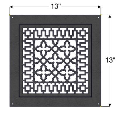
SAFETY FIRST
DO'S AND DONT'S
If this fireplace is not properly installed, a house fire could result. For your safety, follow the installation
directions. Contact your local authority having jurisdiction (such as municipal building department, fire
department, fire prevention bureau, etc.) regarding restrictions and installation requirements, and the need
to obtain a permit.
To ANYONE using this fireplace: these DO's and DONT's are for your safety.
1. DO read this instruction manual before lighting your first fire.
2. DO burn seasoned wood fuel or densified fuel logs or a combination of densified fuel logs and wood fuel.
3. DO operate the fireplace with the door fully closed. If the door is left partly open, gas and flame can be
drawn out of the fireplace opening, creating both fire and smoke hazards.
4. DO keep all combustible materials (furniture, firewood, etc.) at least 4' away from the front of the fireplace.
5. This fireplace needs periodic inspection and repair for proper operation. DO learn to properly use it and maintain
it.
6. DO have at least one smoke detector on each level of the house and at least one carbon monoxide detector.
7. To avoid glass breakage, DO NOT slam the fireplace door.
8. DO NOT ever use gasoline, gasoline-type lantern fuel, kerosene, charcoal lighter fluid or similar liquids to start
or freshen up a fire in this fireplace. Keep all such liquids well away from the fireplace while it is in use.
9. DO NOT overfire the fireplace. If you are unable to slow down the burn rate of the fire or if the chimney connector
behind the top louver glows red, you are overfiring the fireplace.
10. DO NOT use a fireplace grate or other products not specified for use with this fireplace.
11. The burn rates are set by the manual air control at the factory. DO NOT tamper with the air control. DO NOT
install a flue damper that would allow you to reduce the chimney draft and thus slow the minimum burn rate.
12. To avoid damaging the fireplace, DO NOT operate it in a manner inconsistent with the operating instructions in
this manual.
13. DO NOT install an insert in this fireplace.
NOTE: We strongly recommend that our products be installed and serviced
by professionals who are certified by the National Fireplace Institute in the
U.S. or by Wood Energy Technology Transfer Inc. in Canada.
CREOSOTE: FORMATION AND REMOVAL
When wood is burned slowly, it produces tar and other organic vapors which combine with the expelled moisture
from the wood to form creosote. The creosote vapors can condense in the relatively cool chimney of a slow burning
fire. As a result, creosote residue accumulates on the flue lining. When ignited, this creosote makes an extremely
hot fire.
The chimney should be inspected periodically during the heating season to see if a creosote build-up has occurred.
The presence in a chimney of soot or creosote in excess of 1/8" (3mm) thick will indicate the need for immediate
cleaning, possible modification of burning procedures, and more frequent inspections.
FOCUS 3600 Owner's Manual 3 RSF Woodburning Fireplaces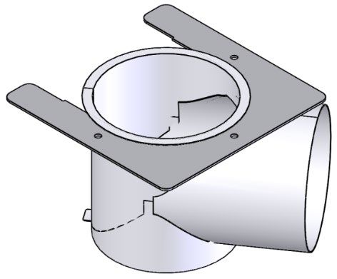
GENERAL SPECIFICATIONS
The FOCUS 3600 is environmentally friendly and meets the 2020 United States Environmental Protection Agency
(EPA) particulate emission standard with cordwood at an average emission rate of 1.5 grams per hour.
It also has an optimal efficiency of 79%. This has been established using the high heating value of the wood, under
the best burning conditions and using CSA B415.1-10 calculations.
This fireplace is suitable for manufactured / mobile home installations, using solid fuel only.
Furthermore, the weighted average EPA efficiency is 74%. The later has been established using the higher heating
value of the wood, while burning EPA cordwood and using CSA B415.1-10 calculations.
It has been shown to deliver heat ranging from 13 000 to 50 000 BTU/h with an average of 25 000BTU/h. Please
refer to the "Improving efficiency”, the “Importance of draft”, the “Brun Time vs. Heat Output” and “Fuel” sections to
better understand the various factors that influence the efficiency and heat output of your fireplace.

MANDATORY FIREPLACE OPTIONS

A choice of trim is required to complete the installation and finishing of the FOCUS 3600

                                   Straight Trim (for heavier masonry) FO-F3600ST
                            The Straight Trim projects straight out the front opening of
                          the fireplace by ¾” when installed. If the finishing material is
                            thick (e.g. brick, stone, etc.), it will provide a finished edge
                                                                             to butt against.

                          Frame Trim (for tile or cement board finish) FO-F3600FT
                          The Frame Trim partially overlaps the wall and covers the
                          edge where the finishing meets the fireplace. It is ideal for
                          installations finished with thin materials (e.g. tile, cement
                          board, etc.).

OPTIONS

Internal Blower (FO-FDHB9): For increased air circulation and marginally more heat output, you can add an
optional fan.
Gravity Vents (FO-V2, FO-VGC or FO-V3): If you have any rooms directly above or adjacent to the room with the
fireplace that you would like to heat, you may want to consider the Gravity Vent Kits. The gravity vent uses ducts
and vents to distributes hot air to these rooms without the need for a blower.
Each gravity vent kit includes 5’ of insulated flexible ducting, a gravity vent starter, an outlet grill adapter, and a
decorative outlet grill. The different grill designs are shown below:
              FO-V2                    FO-VGC (grill only for FO-V2)                             FO-V3

FOCUS 3600 Owner's Manual                                   4                                   RSF Woodburning Fireplaces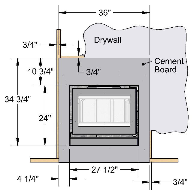
Heat Dump (FO-HD): For a simple way to pull heat away from the fireplace to another room or to the basement, we offer the Heat Dump Kit. It includes a 180 cfm blower and is most often used to prevent the room with the fireplace from overheating and provide supplemental heating to the basement when the fireplace is on the main floor. Gasket Replacement Kit (FO-GRK5): Over time, the door seal will develop wear and eventually needs to be replaced when air leaks into the firebox. If you notice difficulty slowing down the rate of burn or shortened burn times, it may be a good time to replace your door gasket. NOTE: Some options require wiring and/or electricity for their installation. If there is any chance that any of these options will be installed in the future then suitable wiring should be run during framing. Otherwise, it will be difficult to install these options later. You can refer to page 30 for a list of options that require electricity. Detailed installation instructions are included in the box with each option. These can also be obtained from our Internet Web Site: www.icc-rsf.com. WARNING: This fireplace has not been tested with a gas log set (unvented or vented). To reduce risk of fire or injury, do not install a gas log set (unvented or vented) into this fireplace. Do not install a gas log lighter because the heat produced by the fireplace will permanently damage the gas log lighter. FOCUS 3600 Owner's Manual 5 RSF Woodburning Fireplaces
UNIT DIMENSIONS AND CLEARANCES

                                        For the side wall clearance
                      Distance from the side standoff to the side of the firebox opening:
                                                    81/8”

                                      For the mantel shelf clearance
                      Distance from the fireplace base to the top of the firebox opening:
                                                    26 3/8”

  Figure 1 Unit Dimensions

FOCUS 3600 Owner's Manual                             6                               RSF Woodburning Fireplaces
Figure 2 Unit Clearances
Table 1 Unit Dimensions and Clearances
A Distance of combustible material from side, back and top standoffs 0" (0,0 mm)
B Minimum distance from the side wall to the side of the firebox opening 12" (305 mm)
Minimum ceiling clearance: from the bottom of the bottom standoffs (legs)
of the fireplace to the ceiling Standard 6' (1,83 m)
C
• in the enclosure above the fireplace and Mobile home 7’ (2,13 m)
• in the room in front of the fireplace
Minimum chimney height: minimum total chimney height from fireplace top Standard 12' (3,66 m)
D
to below the chimney rain cap – Refer to Table 4 if elbows are present Mobile home 8’ (2,44 m)
Maximum chimney height: maximum total chimney height from fireplace
E 39' (11,88 m)
top to below the chimney rain cap
F Maximum chimney height supported by the fireplace 20' (6,10 m)
Minimum depth of non-combustible hearth extension: from the front of the
G 18" (457 mm)
fireplace
Minimum width of non-combustible hearth extension: total width, must be
H 38½" (978 mm)
centered on the firebox opening
I Minimum width of the spark guard 36" (914 mm)
J Maximum mantel shelf depth (see Table 2 for other mantel sizes) 12" (305 mm)
Minimum height of a combustible mantel shelf above the top of the firebox
K opening: to the bottom of the combustible mantel (refer to the “MANTEL” See Table 2
section for particulars)
L Maximum depth of a combustible mantel post See Table 3
FOCUS 3600 Owner's Manual 7 RSF Woodburning FireplacesINSTALLATION
GENERAL INSTALLATION
Check with your local authority having jurisdiction (such as municipal building department, fire department, fire
prevention bureau, etc.) regarding restrictions and installation requirements, and the need to obtain a permit.
NOTE: We recommend that you remove the door until after all finishing work is completed around the fireplace.
This will reduce the possibility of scratches, vandalism, or damage to the finish caused by drywall dust, muriatic
acid, plaster, cement, paint or any other harmful spray or liquid.
Flashing and Roof Radiation Shield
*see Chimney Installation, paragraph 4 & 5
Figure 3 FOCUS 3600 General Installation
FOCUS 3600 Owner's Manual 8 RSF Woodburning FireplacesLOCATION
We recommend that you take the time to plan your entire installation (fireplace, chimney, and options) before
beginning the actual installation (refer to Figure 3). Your FOCUS 3600 fireplace may be installed in many different
ways (see Figure 4) without any special floor reinforcement.
Dimensions of the fireplace along with clearances are shown in Figure 1 and Table 1.
WARNING: If this fireplace is not properly installed, a house fire can result. For your safety, follow the installation
instructions and clearances. Do not pack required air space with insulation or other materials.
1. Note the location of roof and floor joists. Try to choose a location that does not require cutting them.
2. Do not build recessed shelves or cupboards in the enclosure above the fireplace. This must be kept as air
space.
3. If at all possible, run the chimney up through the inside of the house. If it must be run outside, it should be
enclosed in an insulated enclosure (see Installation: Chase Enclosure). Remember, a cold chimney causes
poor draft.
FRAMING
Walls on all interior sides of the fireplace enclosure should be finished and flat. Insulation or other materials should
not be placed in required clearance spaces around the fireplace. Because of the high heat output potential of the
FOCUS 3600, combustible materials must NOT go closer to the fireplace than the standoffs, top, back and sides.
38
361/2"
3/8” The framing dimensions are larger
than required for ease of
72" installation.
The Heat Dump Option will require
12" at least12" additional space on the
4044"
7/8” selected side. Ensure adequate
space is planned.
23
241/2”
1/2"
36 3/8"
16 3/4"
23 1/2"
FOCUS 3600 Owner's Manual 9 RSF Woodburning FireplacesFigure 4 FOCUS 3600 Framing Examples CEILING CLEARANCE Ceiling clearance is the distance from the bottom of the bottom standoffs (legs) of the fireplace to the ceiling. Under no circumstances should the distance between the ceiling firestop and the base fireplace be less than the dimension specified in Table 1 (C). The minimum ceiling clearance applies both to the room in which the fireplce is installed, and the enclosure in which it is framed. SECURING THE FIREPLACE IN PLACE Once the fireplace is in its final location, take the time to attach it to the floor. Using at least two of the five small brackets that were securing the fireplace to the crate, attach the casing of the fireplace to the floor. If possible, try to have at least one, if not two, of the brackets screwed into the floor joists with 2" wood screws. TOP STANDOFF INSTALLATION The Top Standoff provides clearance to combustible framing and includes a heat shield as part of its design. The Top Standoff MUST be installed to avoid fire and ensure a safe installation. Screw the Top Standoff to the top of the unit in the location shown using the screws provided. For shipping, the top standoff is flat. During installation, the back shield must be bent along the crease to a 45° angle. When placing 2x4 framing along the Top Standoff, ensure an air gap of at least ¼” from framing to the back shield. DO NOT fill the gap between the fireplace and the standoff with insulation or any other material; it will be covered with the finishing material. NOTHING CAN BE PLACED BELOW THE HEADER SUPPORTS OF THE TOP STANDOFF WHETHER COMBUSTIBLE OR NOT. THE SPACE MUST REMAIN EMPTY. FOCUS 3600 Owner's Manual 10 RSF Woodburning Fireplaces
Air Space
                                                                     45°                            2x4 wood
                                                                                                    framing

                          Bend Crease
                                                                                                                   Back Shield

   Figure 5 Top Standoff Installation
                                                          *generic image may not directly reflect your fireplace
OUTSIDE AIR DUCT                                                Above Floor                                          Below Floor
                                                                   Example                                           Example
The use of outside air is not required unless

                                                                               re SF
                                                                                      e

                                                                                                       re SF
                                                                                                              e
                                                                                    ac

                                                                                                            ac
                                                                                  R

                                                                                                          R
                                                                                 pl

                                                                                                         pl
specified by local building codes or it is installed in

                                                                               Fi

                                                                                                       Fi
a mobile home. The FOCUS 3600 includes a
rotating elbow that connects to the bottom of the unit
and can exit in any direction.
Use an insulated aluminium flexible duct rated at
over 200° F. The duct should not exceed 12' vertical
rise above the base of the unit. We suggest using
                                                                                          2" Aluminium                  Outside Air
the 4" RSF outside air kit (FO-INT).                                                       Duct Tape                    Inlet
To avoid condensation, it is recommended to use an
                                                                       re SF
                                                                              e

insulated duct long enough to include a «P-Trap»
                                                                            ac
                                                                          R
                                                                         pl

loop.
                                                                        Fi

The air inlet should always be at least 5’ lower                Insulated Flexible Air Duct
than the chimney rain cap and must never
terminate in attic spaces.                                                            Outside Wall

A 4" diameter duct can be used if the total duct run     Figure 6 Outside Air Connection and Installation
is less than 25'. For longer runs, use 5" diameter
duct. For a 5" run, you will need to start at the fireplace in 4" just to get from under the base and then use an
increaser from 4" to 5" to be able to continue in 5".
1. Use a short Phillips screwdriver to remove the outside air cover located on the bottom of the fireplace, four
   screws hold it in place (see Figure 7).
2. Bend the central part of the cover back and forth to break away the two tabs and remove the central part.
3. Attach the 4" aluminium duct to the inlet of the outside air elbow with metal screws and aluminum tape.
4. If the insulated flexible duct has a plastic covering, remove this plastic cover over the flexible duct so that there
   is no plastic cover on the duct under the fireplace and for at least 3" away from the fireplace. The plastic cover
   MUST NOT get within 3" of the fireplace.
5. Tape the insulation to the aluminum ducting where the plastic cover was pulled back. Using aluminium tape to
   hold it in place.
6. If using 5" flexible duct for the rest of the duct run, cut the 4" insulated flexible duct long enough to clear the
   fireplace. Completely remove the plastic cover over the 4" duct. Pull back the insulation on the extremity of the
   4" duct and attach it to a 4"-5" increaser (not included) with metal screws. Pull back the plastic cover and the
   insulation from one extremity of the 5" duct. Attach that extremity of the 5" aluminium duct to the 4"-5" increaser
   with metal screws. Replace the insulation and plastic over the 4" and 5" insulated flexible duct and tape it in
   place with aluminium duct tape. Remember, the plastic cover MUST NOT get within 3" of the fireplace.

FOCUS 3600 Owner's Manual                                  11                                         RSF Woodburning Fireplaces
Figure 7 Outside Air Cover
7. Insert the outside air elbow into the support and install this assembly onto the fireplace, using at least two of
the screws that were removed previously but do not tighten it yet.
8. Orient the outside air elbow in the direction you want the outside air duct to go and tighten the screws, then
seal the connection with aluminum tape.
9. Make a 4 ¼" (5 ¼" if using a 5" diameter duct) hole in the outside wall of the house. Push the outside air inlet
in from the outside. Seal the joint between the air inlet and the outside wall with an appropriate sealant.
10. Place the insulated flexible duct over the round sleeve on the outside air inlet. Carefully pull back the insulation
and plastic cover, exposing the flexible duct. Attach the duct with metal screws to the air inlet. Replace the
insulation and cover back over the duct. Tape the plastic cover in place with aluminium duct tape.
CAUTION: WHEN RUNNING THE DUCT AROUND CORNERS, BE SURE TO PREVENT CRIMPING THE
DUCT IN A WAY THAT WOULD RESTRICT THE COMBUSTION AIRFLOW.
FINISHING AROUND THE FIREPLACE
Screws permitted
Before applying your choice of finishing (e.g. stone, tile, etc.) the facing
MUST be covered with cement board panels that are at least ½” thick.
Only fully non-combustible panels such as James Hardie
HardieBacker® or USG Durock® cement board are acceptable. Both
products will allow for face finishing with any non-combustible material
and will allow you to create a seamless joint.
To secure the cement board in place, screw into the framing beside the
fireplace or directly into the grey region on the fireplace indicated in
Figure 8.
WARNING: Do not use gypsum board to cover the fireplace, it is
considered a combustible material regardless of the fire rating.
Facing Requirements
Finishing materials that cover the facing of the fireplace MUST BE
NON-COMBUSTIBLE (e.g. brick, slate, ceramic tile, etc.). Drywall
cannot get closer to the fireplace than the side and top standoffs. The
front face of the top standoff is considered part of the fireplace facing.
The minimum size of a non-combustible facing is shown in Figure 9. Figure 8 Screw Locations
FOCUS 3600 Owner's Manual 12 RSF Woodburning FireplacesFigure 9 Minimum Requirements for Non-combustible Facing
Mandatory Trim Installation
A choice of trim is required to complete the finishing of the FOCUS 3600. You have two choices in trim, both trims
install in the same manner using the rivets provided. Removing the door may be necessary to install all the rivets
provided (see Figure 10). Unlatch the door and lift it vertically to remove it. Install the two louver pins which can be
found in the manual bag (see Figure 11).
Straight Trim (FO-F3600ST) - The straight trim provides a finished edge for masonry or stone to butt against. It
projects out from the facing to provide a straight flat edge in which to butt against.
Frame Trim (FO-F3600FT) - The frame trim provides a frame-like finish which overlaps the finishing material on
the facing in order to hide the cut edge of the finishing. It has an adjustable depth to accommodate various
thicknesses of materials. It works best with thin, flat finishing, such as cement board or tile.
x13
Figure 10 Trim Installation Figure 11 Louver Pin Installation
FOCUS 3600 Owner's Manual 13 RSF Woodburning FireplacesMANTEL
Masonry and other non-combustible mantels (shelf and posts) can be 12"
placed anywhere around the fireplace facing. If the non-combustible
mantel is located between the top of the fireplace facing and the
specified height for a combustible mantel, then the wall portion
between the top of the fireplace facing and the mantel must be 0" - 4"
covered in non-combustible material. If the non-combustible mantel
is located at the same height allowed for a combustible mantel, or
higher, then no special wall covering is required below the mantel. 51"
If the combustible mantel shelf has a cross-section with variable
depth, it has to be installed so that its widest part is not installed lower 44"
than the corresponding minimum installation height while making
sure that the lowest point of the mantel is not installed lower the
minimum installation height corresponding to its depth (Table 2).
Mantel depth is always measured from the face of the fireplace (see
Figure 12). This is regardless of the depth of materials used for
finishing the facing.
Vertical mantel posts are permitted on either the side of the fireplace
facing. If they made from combustible materials, the mantel posts
require the clearances specified in Table 3. Figure 12 Mantel Requirements
Table 2 Various Mantel Shelf Depths and Corresponding Installation Heights
Minimum Installation Height Minimum Installation Height
Maximum Mantel Shelf Depth
from Top of door opening from Bottom of Unit
0" to 4" 17" 44”
5” 17 7/8” 44 7/8”
6” 18 3/4” 45 3/4”
7” 19 5/8” 46 5/8”
8” 20 1/2” 47 ½”
9” 21 3/8” 48 3/8”
10” 22 1/4” 49 1/4”
11” 23 1/8” 50 1/8”
12" 24" 51”
Table 3 Mantel Post Clearance
Mantel Post depth in front of the Minimum distance from the side of
facing of the fireplace the fireplace opening.
0" to 3" 7"
3” – 7.5” 8”
7.5-12” 9”
CHIMNEY
This fireplace is certified for use with 6" ICC Model EXCEL chimney only. Please refer to Table 1 (D-E) for the
minimum and maximum chimney heights permitted with the FOCUS 3600 fireplace.
We recommend that the minimum height be increased by approximately 6" for every 1000' elevation above sea
level. Every 15°, 30° or 45° offset (one pair of elbows) also increases the minimum height. See Table 4 for more
precise recommended flue heights.
For example, if you are living 6015' above sea level, your chimney should terminate at least 15' from the top of the
fireplace if it is a straight chimney or at least 18'6" if one 30° offset is used as shown in Table 4.
FOCUS 3600 Owner's Manual 14 RSF Woodburning FireplacesTable 4 Minimum Recommended Flue Heights
Number of Offset
Elevation (ft) Straight
1 x 15° 2 x 15° 1 x 30° 2 x 30° 1 x 45° 2 x 45°
Chimney
Minimum
0 - 1000 13’ 14’ 15’ 18’ 16’ 20’
12’
1001 - 2000 12’6” 13’6” 14’6” 15’6” 19’ 16’6” 20’
2001 - 3000 13’ 14’ 15’ 16’ 19’6” 17’ 21’6”
3001 - 4000 13’6” 14’6” 15’6” 17’ 20’ 18’ 22’6”
4001 - 5000 14’ 15’ 16’ 17’6” 21’ 18’6” 23’
5001 - 6000 14’6” 15’6” 17’ 18’ 21’6” 19’ 24’
6001 - 7000 15’ 16’ 17’6” 18’6” 22’ 20’ 24’6”
7001 - 8000 15’6” 16’6” 18’ 19’ 23’ 20’6” 25’6”
8001 - 9000 16’ 17’ 18’6” 20’ 24’ 21’ 26’6”
9001 - 10000 16’6” 17’6” 19’ 20’6” 24’6” 22’ 27’
Flue height is measured from the top of the fireplace to the top of the chimney before installing the rain cap.
If you have two different offsets (two pairs of different elbows), simply use the column for two offsets of the
biggest pair of elbows at your elevation to get your Minimum Flue Height.
CHIMNEY INSTALLATION
Make sure to read the EXCEL Chimney installation manual concerning requirements for supports, bracing,
anchors, etc. Refer to Table 1 (F) for the maximum chimney height that can be supported by the top of the fireplace.
WARNING: The clearance between the chimney and combustible material must be 2" or more. Do not fill this
area with insulation.
1. Cut and frame the required holes in the floor(s), ceiling(s) and roof where the chimney will pass through. The
rough opening in the framing is 12" square (the opening can be slightly bigger, but NEVER smaller).
2. From below, install a radiation shield in each floor through which the chimney passes. At the attic level, install
a radiation shield and a storm collar as shown in Figure 13
WARNING: A radiation shield must be installed at each floor where the chimney passes through.
3. Place the first length of chimney on the fireplace. Secure the chimney length to the fireplace with the three
screws provided. Assemble the rest of the chimney.
The chimney must extend at least 3' above its point of contact with the roof and at least 2' higher than any wall,
roof, or building within 10' of it. If the chimney is higher than 5' above the roof, it must be secured using a roof
brace.
FOCUS 3600 Owner's Manual 15 RSF Woodburning Fireplaces4. At the roof, install a roof radiation shield (XM-
6ERRS). The roof radiation shield must be
installed so it extends 3" above the roof line.
5. Put the roof flashing into place.
• If the chimney is enclosed to the roof: use
a vented flashing.
• If the chimney is not enclosed to the roof:
use a regular flashing.
WARNING: Do not block any of the openings in the
vented flashing with sealant, caulking or any other
materials.
6. Place the storm collar over the chimney and
flashing. Place a bead of exterior sealant around
the chimney below the storm collar, pull the storm
collar through the sealant and seal it once again
on the top with the exterior sealant (DO NOT use
roofing tar).
7. Fit the rain cap on the chimney. Secure it tightly
in place.
OFFSET CHIMNEY
An elbow may be installed directly on top of the
*Refer to text to determine the appropriate flashing
fireplace if required. See the detailed offset charts in
the EXCEL chimney installation manual. Use the Figure 13 General Chimney Installation
offset option if you need to clear a joist or pass around
a cupboard. See Figure 14 and Figure 15 for examples.
• Maximum offset angle:
• In USA: 30°;
• In Canada: 45°.
• Maximum number of elbows: four, resulting in two offsets and returns.
Install the fireplace and chimney as described earlier. When you require an elbow, proceed as follows:
1. Install the required elbow. Turn it in the desired direction, and fasten it to the chimney length with the three
metal screws provided at the joints.
2. Install enough lengths to obtain the desired offset. Secure each joint with three metal screws. Refer to the offset
charts provided with the EXCEL chimney installation manual for exact offset dimensions.
If the chimney goes through an outside wall as shown in Figure 15 and is enclosed on the other side of the wall,
then the outside plate of the angled wall rediation shield MUST NOT be installed.
3. Use another elbow to return the chimney to the vertical direction.
4. Install a roof support, a wall support, or an offset support above each offset to support the weight of the chimney
(elbows are not designed to support the chimney above an offset).
Through the Wall Offset
You can also go through the wall at an angle starting directly at the fireplace as depicted in Figure 15.
An angled wall insulated radiation shield (XM-6EWRSI30 or XM-6EWRSI45) must be used wherever the chimney
passed through an exterior wall. Make sure you have enough ceiling height. If not, you might want to consider
installing the fireplace in an outside chase.
If the chimney is enclosed once outside of the house, do not install the outside plate of the angled wall insulated
radiation shield.
Refer to the angled wall insulated radiation shield installation sheets for more detailed installations instructions.
FOCUS 3600 Owner's Manual 16 RSF Woodburning FireplacesRadiation
Shield
Rise
Use Offset
Support or
Offset
Roof Support
Radiation
Shield
3 Metal Screws
in Each Joint
SF ce
R pla
re
Fi
* Refer to the text to determine the appropriate flashing
Figure 14 Offset Chimney Installation Example Figure 15 Offset Chimney Through a Wall Example
FOCUS 3600 Owner's Manual 17 RSF Woodburning FireplacesCHASE ENCLOSURE
If the chimney runs up the outside of the house, we
recommend that it be enclosed in a chase structure. The
chase should be constructed in such a way that it is an
extension of the home (see Figure 16). It should be well
insulated between the footings and the floor of the home to
prevent heat loss. If the climate in your area is mild, insulate
the chase at least to the first firestop. If the climate in your
area is very cold, insulate the chase to the top to keep the
chimney warmer, increase the draft, and reduce creosote
buildup. We also recommend insulating the ceiling of the
chase just as if it were in the attic space. This will prevent
cold air from dropping down through the chase and into the
room where the fireplace is installed (see Figure 16).
Some local codes require that the walls be insulated, vapor
sealed and sheathed with a fire rated gypsum board (see
Figure 16). We strongly recommend this procedure for all
installations to prevent cold drafts from originating in the
fireplace enclosure. If you follow this procedure, we
recommend that you do not insulate the wall above the front
of the fireplace.
REMEMBER: Check local codes concerning installation
requirements and restrictions in your area.
MASONRY CHIMNEY
Installing your FOCUS 3600 fireplace with a masonry
chimney still requires using EXCEL chimney from the top of
the fireplace to where it will connect to a listed liner that will
run up inside the masonry chimney (see Figure 17). *Refer to text to determine the appropriate flashing
The stainless-steel liner should be fitted inside the clay liner Figure 16 Chimney Installed with a Chase
all the way to the top of the masonry chimney. It is not meant Enclosure Example
to replace the clay liner. You can use either the EXCEL liner
or any other listed liner to ULC-S635, ULC-S640 or UL-1777.
Special care is to be taken to make sure that you have a good solid connection between the EXCEL chimney and
the liner. A masonry adaptor (FO-FDM6) was designed specifically for that purpose and is available from your RSF
dealer. It will attach to the liner with 3
stainless steel rivets (provided) and
EXCEL liner or other listed liner to Clearances as per
to the EXCEL chimney with 3 screws ULC-S635, ULC-S640 or UL-1777 NBC or NFPA 211
(provided).
After mortaring in place, the Metal
connection between the EXCEL 12" min. to Firestop
chimney and the liner should not be combustible ceiling Mortar
visible in order to isolate the heat
released through the liner from the EXCEL chimney
fireplace enclosure. lenght: 18" min. Liner
Elbow
As depicted in Figure 17, you must EXCEL chimney
elbow Mortar
install at least one 18" length of
EXCEL chimney after the EXCEL
chimney elbow. The uppermost part Masonry Adaptor
of the EXCEL chimney - where it FO-FDM7
FO-FDM6
re SF
e
enters the masonry chimney - must
ac
R
pl
be a minimum of 12" from the ceiling.
Fi
NOTE: If the ceiling is high enough,
you can install one or more EXCEL Figure 17 Connection to a Masonry Chimney
FOCUS 3600 Owner's Manual 18 RSF Woodburning Fireplaceschimney lengths directly on the fireplace before the elbow.
If you use a flexible liner, make sure to be careful when cleaning to ensure that the stainless-steel flexible liner is
not dislodged in any way.
Using an Existing Masonry Chimney
WARNING: If you are considering using an existing chimney, it must first be thoroughly inspected by an authority
having jurisdiction to determine the following:
1. The masonry chimney is well constructed and fully lined, in accordance with Local Building Codes and the
National Building Code of Canada (NBC) or National Fire Protection Association chimney standard (NFPA 211).
2. It has been thoroughly cleaned of any soot or creosote residue and inspected to determine that it is in good
working condition.
3. There is no insulation of any type in contact with the masonry chimney and there is no insulation stuffed
anywhere in the chimney.
4. All the necessary clearances around the masonry chimney, along the complete run of the chimney, are
respected as per NBC or NFPA 211. If the masonry chimney is enclosed in drywall, openings will probably be
required in order to verify clearances at all points.
5. The masonry chimney will only be used for the fireplace and no other appliance.
If major repairs are required to meet the above conditions, a new chimney should be constructed.
To make the hole through the masonry chimney and make the connection to the fireplace, we recommend that you
follow these steps:
1. Sight-in and mark the outline of where the EXCEL chimney will penetrate the masonry chimney.
2. Using a large (¾" - 2") masonry drill bit, drill a hole exactly in the center of the oval outline. With a masonry
hammer and drill, slowly enlarge the hole to the size required. Remember to work from the center out. Be
especially careful with the clay liner behind the brick because three sides of it must stay in place.
3. Bring the stainless-steel liner down from the top of the chimney.
If you are using a rigid liner you will need enough room to secure an elbow to it with at least two screws.
If it is difficult to install rigid stainless steel liner in the existing masonry chimney or for a masonry chimney with
less than 8"x8" inside, a listed stainless steel flexible liner can be used along with a flexible/rigid adaptor (LM-
6LAF) available from your RSF dealer.
4. Install the liner elbow and masonry adaptor on the lower end of the liner.
5. Move the fireplace forward enough to install the EXCEL chimney on the fireplace (elbow and length) then move
the fireplace back into position as you connect the masonry adaptor to the EXCEL chimney.
Using a New Masonry chimney
Since the masonry chimney is not build yet, we recommend that you position your fireplace, install the EXCEL
chimney on it and connect to the first length of liner before building the chimney as explained above and shown in
Figure 17. The liner sections can easily be installed as the layers of brick are being placed. Since this is a new
chimney, we recommend that you build it to the right size, so you do not have to ovalize the liner.
Remember: The stainless-steel liner should be fitted inside the clay liner all the way to the top of the masonry
chimney. It is not meant to replace the clay liner.
HEARTH EXTENSION
The area immediately in front of the fireplace must be protected by a non-combustible material such as brick, tile,
stone, or slate. Refer to Table 1 (G-H) for the depth and width that the hearth protection should extend beyond the
front and both sides of the door opening (see Figure 1). There is no minimum thickness required for the hearth
extension.
FOCUS 3600 Owner's Manual 19 RSF Woodburning FireplacesBENEATH THE HEARTH EXTENSION
If the FOCUS 3600 is installed on a non-combustible floor,
NONE of the cement board and the spark guard specified below
is not required.
Install the spark guard provided (5" x 36" piece of sheet metal)
halfway under the fireplace and halfway under the hearth
extension and centered on the door opening. The spark guard
will extend 2½" beneath the fireplace. This will make certain that
sparks cannot lodge in this area and start a fire. If necessary,
the provided spark guard can be cut to the minimum width
specified in Table 1 (I).
If you are preparing a raised installation, you will need a custom
made spark guard, either a "Z" shaped spark guard or a right
angle spark guard. The Z-shaped spark guard must be used if
the height between the bottom of the fireplace and the top of Hearth
Extension Spark Guard
the non-combustible flooring of the hearth extension is less than (provided)
or equal to 2 ½". The height of the Z-shaped spark guard must
equal the distance between the floor and the base of the unit
and go under the hearth extension and the fireplace by at least 2½". If the unit is installed higher than 2 ½" from the
top of the flooring, a right-angle spark guard is necessary. The sides of the right-angle spark guard should be at
least 2½" x 2½" and must be covered with non-combustible material. Any custom made spark guard must have the
minimum width specified in Table 1(I), and be installed centered on the door opening.
Flush Hearth Raised Hearth
Cement Focus 3600 Fireplace Focus 3600 Fireplace
Board or
facing 18"
A raised hearth extension
18" min. must be fully non-combustible
Hearth Spark Guard Spark Guard
2 1/2" (provided)
Extension (provided)
Custom Spark Guard Raised Unit
RSF
Fireplace
Focus 3600 Fireplace
Non-
Combustible
Flooring More than 2 1/2"
Cement
2 1/2" or less
Board or Spark Guard
Non- facing (provided)
Right Angle Combustible Z-Shaped Spark
Spark Guard Flooring Guard (not Rais ed platform c an be made from
18" min. c ombus tible or non-c ombus tible materials
(not provided) provided)
Hearth Right Angle Spark
NOTE: Custom-made spark guards are site built. Extension Guard (not provided)
Figure 18 Hearth Requirements
FOCUS 3600 Owner's Manual 20 RSF Woodburning FireplacesMOBILE HOME REQUIREMENTS
These requirements apply to installations in manufactured homes,
mobile homes, and transportable buildings. The term “mobile home”
is used in the following text interchangeably for all setups.
WARNING: Do not install this fireplace in the bedroom or sleeping
room of a mobile home.
An outside air kit is required for mobile home installations. This will
avoid the possible effects of room air starvation, icing, exhaust fans,
etc. The optional kit FO-INT is recommended. See Outside Air Duct
section for details.
A spark screen is required on the chimney cap. The optional ERCS
spark screen must be installed in mobile home installations.
The fireplace must be secured to the floor. Using two #8 wood screws
that are at least 1 ½” long, screw through the holes in the bottom
standoffs, directly into the floor to secure it (see Figure 19).
Figure 19 Secure to Floor
WARNING: The structural integrity of the mobile home floor, walls,
and ceiling/roof must be maintained.
If the chimney exits the mobile home through the wall at a point 7 feet
(2.1m) or less above the ground level on which the mobile home is
positioned, the chimney must be enclosed within a chase enclosure.
See the section Chase Enclosure, and Figure 15
for details.
To maintain building integrity, a radiation shield is required at the
ceiling/roof. It must extend completely through the ceiling/roof cavity
to the outermost plane of the roof. If necessary, it can be trimmed flush
with the plane of the roof to ease installation of the flashing (see Figure
20).
WARNING: In some circumstances, using only the 8’ minimum of
chimney may result in dirtier glass than using 12’ of chimney. Figure 20 Roof Requirements
REFRACTORY BRICK INSTALLATION
Before lighting your first fire, you must make sure the
refractory bricks are properly installed inside the firebox. To
remove any of the refractory bricks, just follow the installation
procedure in the reverse sequence. Refer to Figure 21 to
identify which refractory brick is the left and which is the right
at each step of the installation.
1. Start by placing the rear refractory brick in the firebox (1),
then the right and left side (2, 3) refractory bricks.
2. Continue by installing the soft insulation (4) on the bottom
of the firebox. It fits tight between the front and the back
refractory brick and between both side refractory bricks.
3. Then install the bottom refractory brick (5).
4. Finally, install the two front refractory bricks (6, 7).
These refractory bricks have been designed specifically for
the FOCUS 3600 and no modifications are required to ensure
a proper fit.
Figure 21 Refractory Bricks Installation
FOCUS 3600 Owner's Manual 21 RSF Woodburning FireplacesOPERATION AIR CONTROLS CLOSED OPEN The FOCUS 3600 has two separate air controls. The Combustion Air Control regulates the rate of burn, and the Outside Air control determines where combustion air is drawn from (outside or inside the home). Combustion Air Control Unlike most open fireplaces, RSF fireplaces don’t have flue dampers. Instead, the system is sealed by closing the door, and the amount of air entering the firebox is controlled by the combustion air control lever (see Figure 22). Figure 22 Combustion Air Control Use the handle or gloves provided to adjust the combustion air control. Setting the air control lever all the way open (towards the right) will allow the maximum amount of air into the firebox. Closing the air control (towards the left) will reduce the amount of air entering the firebox. WARNING: When the fireplace is in operation, the combustion air control will become hot enough to burn. Use the handle provided to adjust the combustion control lever. Controlling your fire To get maximum efficiency out of your fireplace you will want to adjust the amount of air entering the firebox at the appropriate times. Gauge how much to close the combustion air by how the fire reacts once the combustion air control lever has been moved. If the fire goes out and begins to smolder, there’s too little combustion air entering the firebox. If this happens, reopen the combustion air control and wait a little longer before attempting to restrict the air again. If there’s no change to the burn pattern, you can continue to close the combustion air further. Always close the combustion air control gradually, never from maximum to minimum in an instant. Eventually you should be able to close the combustion air all or most of the way. There should always be visible fire inside the firebox at every step of the process. It is normal for some installations that the air control cannot be fully closed and maintain a fire. Every home, installation, and draft is unique. Ensure there is visible flame to keep the glass and chimney clean. If adjusting your air control has no affect on the rate of burn, there is air leaking into th e firebox. It is likely occuring at the door, and the rope gasket may need to be replaced. If this happens cease use of the fireplace until the air leak has been found and resolved. You can order a new door gasket from your retailer with the part code FO-GRK5. Outside Air Control The FOCUS 3600 is designed to use outside air for combustion. A shutter located behind the bottom louver will open or close the flow of air from outside into the fireplace. If the fireplace is connected to outside air, the Outside Air Control should be set in the Open position when it is in use. If the fireplace is not connected to outside air, or it is not in use for an extended period (summertime) then it should be in the Closed position. To access the outside air control lever, first remove the bottom louver trim by lifting slightly and by pulling on it (see Figure 23). WARNING: When the fireplace is in operation, the bottom louver trim and outside air control may become hot enough to burn. Use the gloves provided if the fireplace is hot. FOCUS 3600 Owner's Manual 22 RSF Woodburning Fireplaces
Figure 23 Outside Air Control Location

Rotating the outside air control lever so that it faces forward will open the outside air damper and allow fresh air into
fireplace. Because outside air is generally colder and denser it will help to start the fire. In some cases, fresh air will
help compensate for negative pressure problems within the house; however, it will not prevent the fireplace from
smoking in severely depressurized homes or inadequate draft situations.
It is recommended to use outside air for combustion, but you may choose to use room air for combustion instead.
To do so, turn the outside air control lever so it is pointing upwards to close the outside air damper. This control
should be closed to outside air when the fireplace is not burning to prevent cold air infiltration.

  Open to outside air                                            Closed to outside air
                                     Air Flow

  Closed to room air                                             Open to room air

 Figure 24 Outside Air Control Operation

LIGHTING

Ensure that the combustion air control lever is all the way in the open position. You will want as much air as possible
for the lighting process.
We recommend that you prepare your fire in a top-down fashion. This will make for a faster start and a cleaner burn
while starting. . Build your fire behind the front bricks to avoid spillage during reloading.
Start by laying 2-3 layers of small wood pieces (about 10 pieces of 1" to 2" in diameter). Criss-cross the pieces so
there is plenty of air circulation in between. Then continue by criss-crossing your kindling (about 20 pieces the size
of your fingers) on top of the small wood. You can then add a few pieces of paper on top. Never use any flammable
liquid. Light the fire at the top of the pile and close the door most of the way, but do not shut it completely. If the
door is positioned correctly you will see air rushing into the fireplace, this will help the lighting process. Wait about
2 minutes and then close the door completely. The fire should continue to burn. If it looks like it wants to smolder,
crack the door open for another minute or two before closing it again. The amount of time to keep the door slightly

FOCUS 3600 Owner's Manual                                   23                                RSF Woodburning Fireplaces
ajar at startup is dependant on the height of your chimney and the outside temperature: the higher and the colder,
the longer the door needs to remains cracked.
Once most of the startup fuel is down to a nice coal bed, rake the hot coals towards the front and add cordwood
according to you needs, up to 6 logs at a time. Air enters the firebox at the front, and raking coals forward will help
your cordwood to light. The bottom layer of logs should be oriented front to back (i.e. North/South). The second
layer should then be oriented left to right. Always put at least 2 layers of logs criss-crossed together, this will help
them to light to burn cleanly. Again keep the door cracked for a couple of minutes while the bottom logs catch on
fire, then you can close the door completely.
Keep the combustion air control on maximum until the next reload. This will help establish a strong draft in the
chimney before you reduce the combustion air, ensuring a cleaner burn at the same time.
WARNING: Do not use a grate or elevate the fire.
WARNING: Make sure to keep the fire behind the front step. Replace the logs if they fall against the glass.
FUEL
All modern high efficiency fireplaces and woodstoves are designed to burn best with seasoned cordwood. Seasoned
wood can be defined as wood that has been cut, split and let dry under cover for a minimum of 6 months, preferably
a year or more. Dry seasoned wood generally contains less than 20% moisture content. Attempting to burn fuel
with a high moisture content will be difficult and result in lower efficiency, increased creosote buildup and dark
deposits on the glass. It’s possible to burn a very large amount of wood and get very little heat if the wood is wet.
The type of wood you select is also important. All types of wood give off more or less the same number of BTU’s
per pound. Since softer woods are less dense than hardwoods it is possible to put more weight of hardwood in the
firebox; in other words, all woodburning appliances will burn longer and more evenly with hardwoods. Never burn
scrap, garbage, treated wood or driftwood as they produce much more pollution and can corrode the firebox and
chimney as well. Burning large amounts of paper, cardboard, mill ends, or construction waste can easily over fire
and damage the fireplace or even ignite a chimney fire if the flue is dirty.
We do not recommend using wax fuel logs (e.g. Duraflame) in this fireplace because it will dirty the glass. If you
choose to use them, do not use more than one at a time and do not poke or stir while it is burning. Use only firelogs
that have been evaluated for fireplace use. In Canada, they must meet the requirements of ANSI/CAN/UL/ULC
2115, Processed Solid Fuel Firelogs and Firestarters. Refer to the firelog warnings and caution markings on
packaging prior to use.
WARNING: Burn dry wood only.
Do not burn: driftwood, treated wood, coal, garbage, or plastic.
FIRST FIRES
You will experience a slow start-up during the first few fires. The refractory bricks lining the firebox contain moisture
from manufacturing and require a few hot fires to evaporate the moisture. While there is still moisture in the bricks,
they will be black with smoke deposits. When the moisture has dissipated, the bricks will turn white. Unlike cast iron
stoves, there is no need to cure the fireplace itself by starting with small fires and progressively larger ones. Feel
free to light a large fire from the very start.
You will experience a slight odor during the first few fires. This odor comes from curing paint and oil burning off the
metal. The odor may be strong enough to set off your smoke detector. Open the doors and windows to allow the
room to properly ventilate.
REFUELING
Have your next wood load ready when you open the door. The temperature in the firebox will decrease as the door
is open, so decreasing the amount of time the door is open will allow the firebox to remain hot. Do not rush.
Turn off the fans, if installed. The fans may cause smoke to spill out of the fireplace if they are running.
The door should be opened slowly to keep smoke from spilling into your room. If you have a problem with smoke
spillage, check to see that all kitchen and bathroom fans have been shut off. They can cause negative pressure in
the house which pulls smoke out of the fireplace.
FOCUS 3600 Owner's Manual 24 RSF Woodburning FireplacesTake the time to poke and stir the unburnt wood that is left in the firebox. This will help revive the fire. Place the
new logs in the firebox. Try to maintain a clear a path in front of the pilot, which is the metal tube centered between
the two andiron posts. The pilot brings an influx of air close to the coals that will help to keep the fire going. Once
the new wood has been loaded, keep the door slightly ajar for a couple of minutes to get the fire going depending
on how well seasoned your cordwood is and how much coals were left in the firebox. Once the new wood it well lit,
close the door.
You can now adjust the combustion air control according to your needs.
If you have an internal blower installed,
• wait about 45 minutes after reloading before you start the blower again if you have the combustion air
control set to anything between half-way to minimum.
• wait about 20 minutes after reloading before you start the blower again if you have the combustion air
control set to anything between half-way to maximum.
IMPROVING EFFICIENCY
The location of your fireplace will affect how efficiently it heats the home. Your fireplace should be located in part of
the house you want to be the warmest. Trying to heat the main floor with a fireplace in the basement will generally
overheat the basement and waste fuel. Certain RSF options offer the ability to move heat from the main floor to the
basement. This allows you to efficiently heat your primary space while also heating the basement as a secondary
space.
The efficiency will also be influenced by the draft in the chimney which will be influenced by various factors (refer
to "Importance of draft" below) and by the amount of wood burning at any point (see "Burn Time vs. Heat Output"
below). The efficiency will also be influenced by the quality of the wood (refer to "Fuel" below).
All of these factors must be taken into account and optimize so you can recover the maximum heat from your
fireplace.
IMPORTANCE OF DRAFT
Draft is the natural force which pulls air from the fireplace up the chimney. The strength of draft in your chimney
depends on a variety of factors, including chimney height, nearby obstructions, altitude, etc.
Excessive draft can result in a hotter fire than intended or reduced burn times as more air is pulled through the
fireplace. It will also result in less heat recovery since the heat will not have as much time to irradiate into the room
before being sucked into the chimney.
Weak draft can result in smoke entering the room and difficulty lighting or operating the fireplace. Weak draft is
often incorrectly associated as a blockage in the air intake for the fireplace. Adding chimney height is the most
common solution. See Table 4 for minimum chimney height recommendations.
BURN TIME VS. HEAT OUTPUT
The faster your fireplace burns the more heat it will create; however, faster fires result in much more hot air flow up
the chimney which means you are sacrificing efficiency. Fast burning fires (lots of air) go through much more wood
than slow burning fires. To get the most out of your FOCUS 3600 fireplace, adjust the combustion air control lever
at the appropriate time. If the fire seems to be burning too quickly, turn the air down. If the fire is smoldering and
there are no visible flames, turn the air up. This way you’ll always be getting the most out of your fuel.
TROUBLESHOOTING PROBLEMS
If smoke comes into the house when the door is opened:
• You may have opened the door too quickly and created a suction of air into the room, this can be avoided by
opening the door more slowly and letting the pressure staibilize before opening it fully.
• Ensure your chimney is clean and your chimney cap is not plugged. Chimney caps with screens are more likely
to become clogged with creosote buildup.
• Make sure you have adequate chimney height for your system. Refer to the Chimney section of this booklet
and make sure to take altitude, and number of elbows into consideration.
FOCUS 3600 Owner's Manual 25 RSF Woodburning Fireplaces• If you have purchased the inline blower, make sure it is off before opening the door.
• Check to see if other fans in the home are running, particularly a kitchen range hood or bathroom exhaust fan.
This can affect the pressure in the home.
• Try opening a window near the fireplace a little, this will equalize the pressure in the home and should correct
a negative pressure problem. Once proper draft is established the window can be closed.
• Make sure you’ve used enough kindling to establish a hot fire quickly. The most likely time that smoke will enter
the home is during the lighting process.
If your fireplace burns excessively fast, seemingly uncontrollably:
• Check all door seals and gaskets to ensure that air is not leaking into the firebox. See “Door Adjustment” for
details of how to verify the tightness of the door. Replace seals as necessary.
• Inspect the secondary air tubes in the top of the fireplace to ensure they are in good condition. An unwanted
hole in the secondary air tubes can bring additional unwanted air into the fireplace.
MAINTENANCE
CHIMNEY CLEANING
Check the chimney for creosote buildup every week or so until experience shows how often you need to clean it. A
buildup of 1/8" (3 mm) or more should be cleaned before more creosote accumulates.
Remove the fireplace baffle prior to sweeping:
• The baffle is a hard insulation panel in the top of the firebox that sits above the tubes. To remove it, start
by removing the front burn tube
• Then slide the baffle towards the front and remove it through the door opening.
5/16"
Figure 25 Tube Removal
Close the fireplace door prior to sweeping.
Remove the chimney cap and sweep the chimney using a 6" round soft bristle brush and remove the accumulated
creosote.
Do not forget to replace both the baffle and the secondary air tube in the same manner as they were removed. Take
care to properly orient the secondary air tube (holes slightly upwards facing) and insert the locking pin to secure it.
DISPOSAL OF ASHES
Remove the ashes before they become too deep, i.e., before you have a spillage problem when you open the door.
The ashes should be placed in a metal container with a tight-fitting lid. The closed container of ashes should be
placed on a non-combustible floor or on the ground, well away from all combustible materials pending final disposal.
FOCUS 3600 Owner's Manual 26 RSF Woodburning FireplacesYou can also read