Design and simulation of air-solar-finned reheating unit: An innovative design of a parabolic trough solar collector - S. N. Nnamchi, O. A ...
←
→
Page content transcription
If your browser does not render page correctly, please read the page content below
Design and simulation of air-solar-finned
reheating unit: An innovative design of
a parabolic trough solar collector
S. N. Nnamchi, O. A. Nnamchi, M. O. Onuorah, K. O. Nkurunziza and S. A. Ismael

Cogent Engineering (2020), 7: 1793453

                                                                                 Page 1 of 30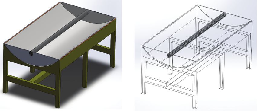
Nnamchi et al., Cogent Engineering (2020), 7: 1793453
https://doi.org/10.1080/23311916.2020.1793453
MECHANICAL ENGINEERING | RESEARCH ARTICLE
Design and simulation of air-solar-finned
reheating unit: An innovative design of
a parabolic trough solar collector
Received: 21 May 2020 S. N. Nnamchi1, O. A. Nnamchi2, M. O. Onuorah3, K. O. Nkurunziza2 and S. A. Ismael2
Accepted: 02 July 2020
Abstract: Design and simulation of air-solar-finned reheating unit, an innovative
Corresponding author: S. N. Nnamchi,
Department of Mechanical design of a parabolic trough solar collector (PTSC) has been demonstrated in this
Engineering, Kampala International work. Fundamentally, the design equations were formulated on the optical and
University, Kampala P.O.B 20000,
Uganda thermal principles. The fundamental optical equations were transformed and
E-mail: stephen.nnamchi@kiu.ac.ug
equated with the original optical equations to realize the optical design functions.
Reviewing editor: The design variables appear in the design function as the unknowns. The design
Zafar Said, Sustainable and
Renewable Energy Engineering, functions were differentiated with respect to the design variables to form design
University of Sharjah, Sharjah United
Arab Emirates simulatory matrices. Prior to the simulation, the design functions were made to
approach zero by the introduction of convergent factors which guarantee the
Additional information is available at
the end of the article convergence of the simulatory matrices whose final output defines the design
variables. The design was algorithmized with a flowchart to justify the design
procedures. A slight obtuse-angled rim design was adopted in the design of the
reheating unit (RU) which yielded optimum; rim angle of 94°, collector, optical and
ABOUT THE AUTHORS PUBLIC INTEREST STATEMENT
NNAMCHI, S. N. Nnamchi is a Senior Lecturer in The design of parabolic trough collector (PTSC)
the Department of Mechanical Engineering (ME) falls into three facets; the acute-angled rim
at Kampala International University (KIU), design, which the focal distance is above the
Uganda. Has made prolific research contribution aperture axis and equally greater than the
in thermofluids, renewable and non-renewable trough’s height, the right-angled rim design,
energy systems; design, modelling and simula which the focal distance lies on the aperture axis
tion. and equal to trough’s height, and the obtuse-
NNAMCHI, O. A. Nnamchi is a postgraduate angled rim design, which the focal distance is
student of Bio-processing and Food Engineering below the aperture axis and less than the
in the Department of Agricultural Engineering trough’s height. The first two facets of the
and Bio resources, Michael Okpara University, designs are prone to misalignment problems and
Nigeria. Her fast rising profile in Bioprocessing, colossal thermal losses. However, the third
Food and Chemical Engineering is valuable to this design facet is not vulnerable to the aforemen
S. N. Nnamchi project. tioned problems but cannot raise the tempera
ONUORAH, M. O. Onuorah is an Associate ture of heat transfer fluid as the first two design
Professor of Applied Mathematics with the facets. Strategically, the present design adopts
Physical Sciences Department, KIU with ample slight obtuse-angled rim design (SOARD) and
publications in Biological, Ecological and finning the reheating unit (innovative PTSC); to
Dynamical systems modelling. enhance heat transfer without impairing the
NKURUNZIZA, K. O.Nkurunziza is efficiencies. Based on the enormous advantages
a postgraduate student of ME at KIU. He’s associated with SOARD, it is recommended for
developing a solar reheating unit with industrial application.
a distinction in air-solar-finned absorber design.
ISMAEL, S. A. Ismael is a dynamic postgraduate
student of ME at KIU. He’s developing a solar
preheating unit with excellence in air-solar-
finned absorber design.
© 2020 The Author(s). This open access article is distributed under a Creative Commons
Attribution (CC-BY) 4.0 license.
Page 2 of 30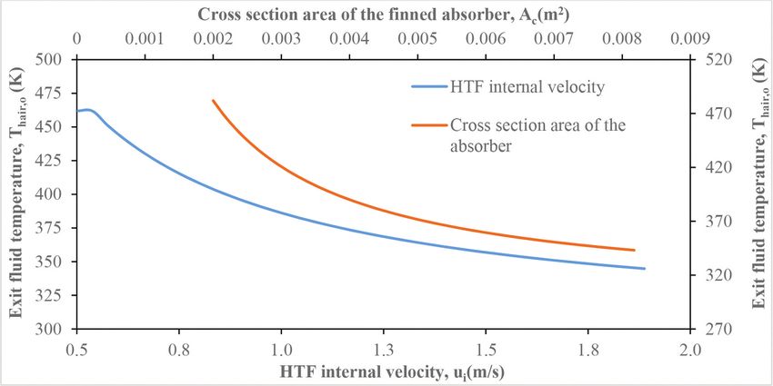
Nnamchi et al., Cogent Engineering (2020), 7: 1793453
https://doi.org/10.1080/23311916.2020.1793453
thermal efficiencies of 0.44, 0.72 and 0.31, respectively, and an optimum exit fluid
temperature of 110o C sequel to the simulation of the design equations. Besides, the
apparent tradeoffs among the design variables were useful in making design deci
sions. Considering the pitfalls of the traditional acute-angled rim design (AARD), the
present work is advocating for the adoption of slight obtuse-angled rim design
(SOARD) technique which will shield the PTSCs from the misalignment issues and
equally minimize the thermal losses prone to the acute-angled rim design techni
que. Also, premium on material selection is recommended for the effective opera
tion of RU.
Subjects: Mechanical Engineering; Heat Transfer; Fluid Mechanics; Power & Energy; Clean
Tech; Design
Keywords: design; design equations; simulation; air-solar-reheating unit; PTSC and design
facets
1. Introduction
The planet Earth is cosmically supplied with enough electromagnetic radiation or wave energy to
support the terrestrial life. However, the technological quests and advancement are demanding
more energy than supported by the nature. Thus, mankind is seriously searching for the different
ways of concentrating the electromagnetic radiation on the planet Earth to provide the technolo
gical and domestic energy demands (Abadal et al., 2014; Gwania et al., 2015). One of the ways of
exploiting more energy from the sun is through the helio-thermal process via the application of
solar concentrators; the parabolic, compound and dish troughs solar collectors.
Therefore, having the in-depth knowledge of the physics, thermodynamics and heat transfer
principles of the smart technologies and efficient processes of harnessing solar energy and
subduing all odds associated with the technology is vital for exploiting more energy from the
sun (Siqueira et al., 2014; Upadhyay et al., 2019). This has been the concern of recent researches in
the renewable energy field. In alliance, the present work is aimed at designing a reheating unit (a
parabolic trough solar collector, PTSC), which serves the thermodynamic purpose of raising the
temperature of heat transfer fluid (HTF; air at 100°C), which is appropriate for drying highly
moisturized agricultural products (Macedo-Valencia, 2014). Conventionally, concentrating power
farm with HTF of high thermodynamic storage capacity (water) can raise steam of high tempera
ture for electricity generation in order to satisfy the industrial and domestic power requirements
without posing any significant threats to the environment (Kumar et al., 2013; Tijani & Bin Roslan,
2014). According to Abdelhady et al. (2017), there are three types of solar concentrators employed
in hi-tech exploitation of electromagnetic radiation; the parabolic troughs, power towers and
parabolic dishes. Effectively, the parabolic trough is widely used in exploiting the electromagnetic
radiation because of the commensurate efficiency of the trough with a high HTF temperature
(Abbood & Mohammed, 2019; Ghodbane & Boumeddane, 2018; Izweik et al., 2016; Tijani & Bin
Roslan, 2014).
A prudent survey of literature has shown that the design of the parabolic trough concentrator
could be influenced by the size of the rim angle, which categorizes the trough designs; the acute-
angled rim design (AARD), the right-angled rim design (RARD) and obtuse-angled rim design
(OARD) of a parabolic trough solar collector (PTSC). Systematically, the acute-angled rim design
is characterized with a flattened trough (the focal distance is greater than the height of the trough)
with an elevated focal distance above the aperture axis of the PTSC. Equitably, the right-angled rim
design has the focal distance equal to the height of the PTSC with the focal point coinciding with
the aperture axis of the PTSC. Practically, the obtuse-angled rim design is characterized by
Page 3 of 30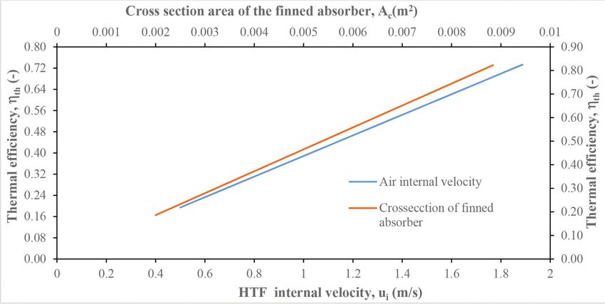
Nnamchi et al., Cogent Engineering (2020), 7: 1793453
https://doi.org/10.1080/23311916.2020.1793453
a depressed focal distance below the aperture axis of the PTSC with the height of the trough
greater than the focal distance. Aphoristically, the depth of the depression for the same aperture
size is governed by the height of the trough; the more the height of the trough, the more the focal
point is depressed towards the apex of the trough and vice versa. Notably, the following workers
(Abdelhady et al., 2017; Gaitan, 2012; Sup et al., 2015) have adopted the acute-angled rim design
approach in the design and performance analysis of the parabolic trough, this facet of design and
performance analysis is susceptible to significant convectional heat loss due to the free flow of
wind around the elevated absorber and if the absorber tube is not properly enveloped with a glass
tube, the efficiency of the collector is surely retarded. In retrospect, they recorded the following
collector design efficiencies of 0.65 and 0.70, respectively. Classically, other researchers (Ghodbane
& Boumeddane, 2018; Kumar et al., 2013; Mohamed, 2013; Montesa et al., 2013) applied the right-
angled rim design technique, which incurs less convectional thermal loss since the trough partially
screens the absorber from the cooling effect of the winds. Consequently, they declared several
collector design efficiencies of 0.37, 0.60, 0.61, and 0.71, respectively. Irrespective of the difference
in the design techniques, the design efficiency published by Abdelhady et al. (2017) is in con
cordance with those of Montesa et al. (2013), and Ghodbane and Boumeddane (2018). Similarly,
the collector design efficiencies by Gaitan (2012) and Kumar et al. (2013) equally concurred with
each other despite the difference in the design methodologies. However, Mohamed (2013) collec
tor efficiency disagrees with the results achieved by both techniques; acute-angled rim design and
right-angled rim design methods. Probably, the difference in the design yardsticks could be
attributed to the difference in the capacity of their troughs and prevailing environmental condi
tions. However, Mohamed (2013) is outstanding in the sense that moderate collector efficiency
(0.37), which indicates that the thermal efficiency is significant or higher exit fluid temperature
could be attained compared to design efficiency (>0.60), which optical efficiency dominates. Based
on the literature survey a good design of PTSC should preserve both optical and thermal efficien
cies, which is feasible by careful design of the focal distance and the height of the trough. Notably,
the three facets of the design of the reheating unit (PTC) as reviewed in the literature were carried
out without a simulator, which does not encourage a tradeoff among the design variables and
could limit the performance of the reheating unit (PTC). However, the present work is pivoted on
a simulatory design technique to ensure proper tradeoff among the design variables, which
engenders optimum optical and thermodynamic performance of the reheating unit (PTC).
Characteristically, Macedo-Valencia et al. (2014) pivoted their design on the obtuse-angled rim
criterion thereon the height of the trough is greater than the focal distance and the absorber is
totally screened by the trough against the wind flow on evacuating the trough with a glass cover,
the risk of thermal loss becomes negligible. However, the more concentration ratio is gained with
the extreme obtuse-angled rim compared to the right-angled rim and acute-angled rim design
techniques. Pertinently, Macedo-Valencia et al. (2014) recorded collector design efficiencies ran
ging from 0.3649 to 0.5057, which are in alignment with that of Mohamed (2013). Generally, the
differences in the collector design efficiencies reviewed could be strongly attributed to the differ
ences in the design considerations and locations. The present work is fascinated by the exclusive
advantages of obtuse-angled rim design to adopt the slight obtuse-angled rim design (SOARD)
technique in the design and simulation of the parabolic trough solar collector (PTSC). Moreover, the
aim of the present design is to diversify the application of PTSC to hi-tech drying technology, by
substituting the heat transfer fluid (HTF; water) in the conventional PTSC designs with air (Huanga
et al., 2016). Superficially, this idea may appear to be impracticable using air as the HTF, which has
a lower thermal storage capacity, but can be directly used in drying operation. However, the
application of air as the HTF with a low thermal storage capacity will be ameliorated by loading
the absorber with a lot of fins, which obviously reduce the cross-sectional area available to the HTF
and enhance the heat transfer phenomenon between the finned absorber and HTF. Thus, the
reduction in mass flowrate of HTF engenders a rise in the exit fluid temperature of the HTF (air),
which could be employed in the direct drying operation. Therefore, the present design considers;
the application of finned absorber in lieu of unfined absorber, the use of air as the HTF against
water and the adoption of slight obtuse-angled rim design (SOARD) technique in the bid to raise
Page 4 of 30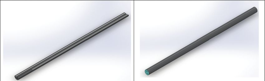
Nnamchi et al., Cogent Engineering (2020), 7: 1793453
https://doi.org/10.1080/23311916.2020.1793453
the temperature of HTF (>100°C) and to achieve substantial collector and thermal efficiencies
(>0.30) through the formulations and simulations of the design equations.
Furthermore, emphasis is laid on the selection of premium materials for the optimum perfor
mance of the finned absorber and in the selection of trough material with a high reflectivity to
enhance the illumination and concentration of solar irradiance on the finned absorber (Ricardo,
2011). Essentially, the present work is algorithmized both in design and simulation processes,
which distinguish it from other designs in the literature.
Subsequently, other sections of this paper will include; materials and method articulated in
a flow chart, further characterized with the formulation of design equations and their simulations,
presentation of results and their discussion, and lastly, conclusions and recommendations.
2. Materials and method
The design of the reheating unit is adapted to the following methodologies:
The design functions or equations were formulated on the fundamental (optical or thermal)
principles. The design variables were identified and incorporated into the design functions or
equations and parameters as the unknown (symbolic) variables.
The simulatory matrices were made of the coefficient (n × n) matrix and column (n × 1) matrix
whose elements were pivoted on the partial derivatives of the design functions or equations with
respect to the design variables (the unknowns) and the design functions, respectively.
Then, the initialization of values of the design variables and the provision of other essential input
data was insightfully done to prepare the simulation process. Prior to the simulation, a check on
the convergence of the design functions has to be carried out; to ascertain whether they are
approaching zero or not (which is an inevitable design condition). Once there is a tendency of
convergence, the simulation is then executed. Otherwise, the odd or nonconvergent terms of the
design functions are identified and multiplied with the convergent factors such that the design
functions have the propensity to approach zero or stand a chance of being converged.
Consequently, the simulation is characterized with a quick convergence as the convergence
criterion is readily attained. The optimal design variables are commensurate with the final output
values that are capable of making the design functions to naturally approach zero.
Thus, the design approach is strongly based on the multiple input and multiple output (MIMO)
approach, which is appropriate for system design (Stoecker, 1989) rather than on single input and
single output (SISO) technique that may not guarantee significant harmony among the design
variables for the optimum performance of the designed system. The entire process or procedure is
carefully algorithmized in Figure 1.
2.1. Formulation of optical design equations
Technically, the design equations are to be governed by optical and thermal behaviours of the
parabolic trough solar collector (PTSC). The optical characteristics of the PTSC are expected to
influence the thermal characteristics of the PTSC. Thus, the overall or collector efficiency of the
system (PTSC) is defined as an attenuated difference in the efficiencies; optical and thermal. The
attenuation factor is equivalent to the heat removal factor. Algorithmically, the optical design is
illustrated in Figure 1, the optical design flowchart describing the design sequence.
The focal point (fpt (m)), the aperture or the width of the parabolic trough solar collector (wpt (m))
and the height (hpt (m)) between the apex and the rim of the parabolic trough collector is
expressed in (Abdelhady et al., 2017; Borah et al., 2013; Ghodbane & Boumeddane, 2018;
Pavlović et al., 2014) as
Page 5 of 30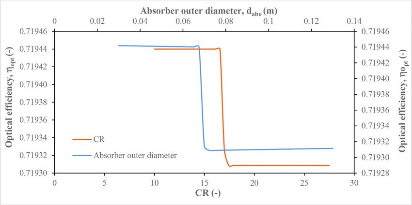
Nnamchi et al., Cogent Engineering (2020), 7: 1793453
https://doi.org/10.1080/23311916.2020.1793453

Figure 1. Optical design
flowchart.

                                                 w2pt
                                        fpt ¼           9 fpt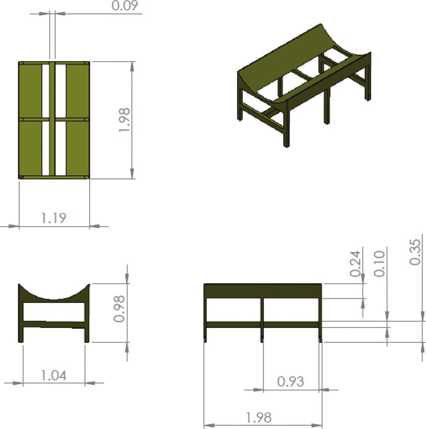
Nnamchi et al., Cogent Engineering (2020), 7: 1793453
https://doi.org/10.1080/23311916.2020.1793453

                                       Transforming with Equation (1) gives

                                            �                                       �2 �0:5
                                       Rpt ¼ 4fpt hpt þ hpt                   fpt

                                                �                �2                         �2 �0:5      �                          �2 �0:5
                                       gop2 ¼       0:5wpt            þ hpt           fpt                    4fpt hpt þ hpt   fpt                9 gop2 ! 0;                  (2)

                                       where gop2 is the second optical design function.

                                        The internal surface area of the parabolic trough collector As,pt (m2) is given in Equation (3) by
                                       Macedo-Valencia et al. (2014) as

                                                       0                                          !0:5            0                        !0:5 11
                                                                          �           �2                                        �     �
                                                        wpt                   4hpt                                 4hpt          4hpt 2
                                       Apt ¼ spt lpt ¼ @                                    þ1           þ 2fpt ln@     þ               þ1      AA lpt
                                                         2                    wpt                                   wpt           wpt

                                       The present work presents a transform of Macedo-Valencia et al. (2014) as

                                                       0                                          !0:5               0                            !0:5 11
                                                                          �          �2                                       �            �2
                                                        wpt                   wpt                                   wpt             wpt
                                       Apt ¼ spt lpt ¼ @                                    þ1           þ 2fpt ln@     þ                       þ1     AA lpt                 (3)
                                                         2                    4fpt                                 4fpt             4fpt

                                       The rim angle of the parabolic trough collector, ψr (degrees) is defined in Equation (4) according to
                                       (Abdelhady et al., 2017; Alfelleg, 2014; Mohamed, 2013; Macedo-Valencia et al., 2014) in Equation
                                       (4) as

                                                         �        �
                                                     1    wpt
                                       ψ r ¼ 2tan
                                                          4fpt

                                       but the present work redefines the rim angle as

                                                         �     �
                                                     1    4hpt
                                       ψ r ¼ 2tan
                                                           wpt

                                       Considering equality in both definitions of rim angle, results in a third independent optical design
                                       equation, gop3

                                                             �        �                         �     �
                                                         1    w                             1    4hpt
                                       gop3 ¼ 2tan                            2tan                      ¼0                                                                    (4)
                                                             4fpt                                 wpt

                                       where              Rpt                 (m)                 is           the        parabolic                radius       of   curvature.

                                         The geometrical concentration ratio (CR) is expressed in Equation (5) (Ghodbane & Boumeddane,
                                       2018; Kuo et al., 2014; Lovegrove & Pye, 2012; Macedo-Valencia et al., 2014)

                                              wpt
                                       CR ¼
                                              dabo

                                       according to the present work, CR is defined as

                                                                                                                                                                     Page 7 of 30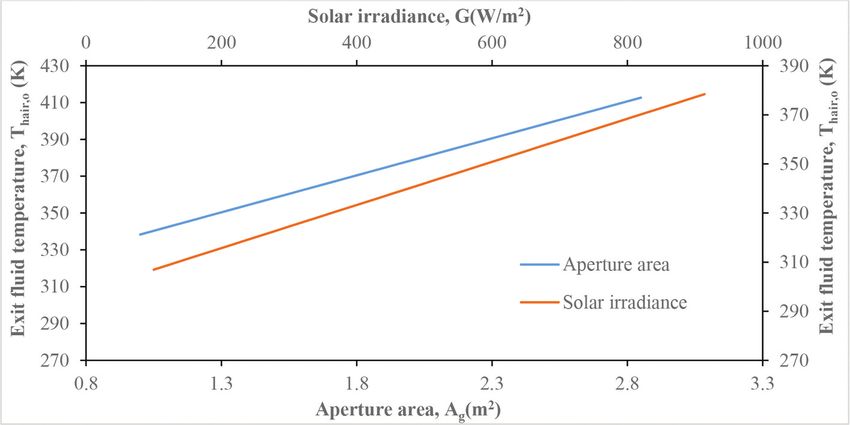
Nnamchi et al., Cogent Engineering (2020), 7: 1793453
https://doi.org/10.1080/23311916.2020.1793453

                                              "      � �2                     �2       �         ��2 #0:5
                                                  wpt 2 þ hpt           fpt    1 þ dabo wpt dabo
                                       CR ¼                2                  �2     �        ��2                                               (5)
                                                  ðdabo =2Þ þ hpt          fpt dabo wpt dabo

                                       where dab (m) is the outer diameter of the absorber.

                                         The optical efficiency, ηopt (-) is given in Equation (6) (Alfelleg, 2014; Pierucci et al., 2014;
                                       Vasquez, 2011)

                                       ηopt ¼ ρpt τg αab γ κðθi Þχend                                                                           (6)

                                       where ρpt (-) is the reflectance of the polished surface of the parabolic trough, τg (-) is the
                                       transmissivity of the glass cover, αab (-) is the absorptivity of the absorber pipe, γ (-) is the
                                       alignment or intercept factor of the absorber pipe (γ ≤ 1), κ (θi) is the incidence angle modifier and
                                       χend (-) is the end loss defined by Alfelleg (2014), Kuo et al. (2014) in Equation (7) as

                                                      fpt
                                       χend ¼ 1           tan θi                                                                                (7)
                                                      lpt

                                       and according to Alfelleg (2014) the incidence angle modifier, κ(θi) in Equation (8) is correlated as

                                       κðθi Þ ¼ 1:2257       0:0072θi þ 0:00003θ2i                                                              (8)

                                       According to Dudley et al. (1994) κ(θi) in Equation (9) is given as

                                                                       θi                         θ2i
                                       κðθi Þ ¼ 1:0 þ 0:000884                      0:00005369                                                  (9)
                                                                     cos θi                      cos θi

                                       Goswami and Kreith (2008) proposed the incidence angle modifier in Equation (10) as

                                       κðθi Þ ¼ 1:0     0:00022307θi               0:0001172θ2i þ 0:00000318596θ3i     0:00000001θ4i          (10)

                                       Similarly, Kalogirou (2004) defined κ(θi) in Equation (11) as follows:

                                                                          θi                       θ2i
                                       κðθi Þ ¼ 1:0 þ 0:0003178                      0:00003985                                               (11)
                                                                        cos θi                    cos θi

                                       In the same vein, Montes et al. (2009) presented κ(θi) in Equation (12) as

                                                                                                     θi             θ2
                                       κðθi Þ ¼ 1:0     0:000525097                0:00002859621          þ 0:00001 i                         (12)
                                                                                                   cos θi          cos θi

                                       The concentrated solar power in Equation (13) is given as

                                       Qsol;ab;con ¼ ηopt Aab G                                                                               (13)

                                       whereas the directly absorbed or non-concentrated solar power in Equation (14) is defined as

                                       Qsol;ab;ncon ¼ τg αab Aab G                                                                            (14)

                                       The subscript g represents the glass cover.

                                                                                                                                       Page 8 of 30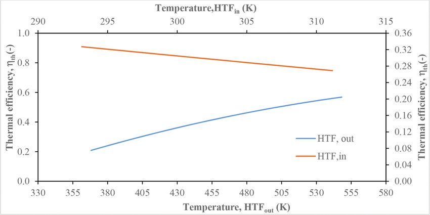
Nnamchi et al., Cogent Engineering (2020), 7: 1793453
https://doi.org/10.1080/23311916.2020.1793453
The total solar power absorbed, Qsol,ab (W) is expressed as
� �
Qsol;ab ¼ Qsol;ab;con þ Qsol;ab;ncon ¼ ηopt Aabo þ τg αab Aabo G (15)
The subscripts con, ncon and g designate the concentrated, non-concentrated heat on the absor
ber and the glass, respectively.
2.1.1. The Simulation of the optical design equations
The optical functions; gop1, gop2, and gop3 (in Equations (1), (2) and (4), respectively, are differen
tiated with respect to fpt, hpt and wpt, respectively, leading to the optical simulatory matrices in
Equation (16):
2 @gop1 @gop1 @gop1 3
2 3 2 3
@fpt
6 @gop2
@hpt @w
7 Δfpt gop1
6 @gop2 @gop2 74 Δhpt 5 ¼ 4 gop2 5
4 @fpt @hpt @w 5 (16)
@gop3 @gop3 @gop3 Δwpt gop3
@fpt @hpt @w
The detailed partial derivative of Equation (16) is presented in the supplementary file. The future
values of the optical design variables and present values are defined in Equation (17) as follows:
fpt;iþ1 ¼ fpt;i þ Δfpt ; hpt;iþ1 ¼ hpt;i þ Δhpt ;
(17)
wpt;iþ1 ¼ wpt;i þ Δwpt ; i ¼ 0; 1; 2
The final optical design variables are established the moment the set convergence criterion
(ζop ¼ 10 3 ) in Equation (18) is satisfied
fpt;iþ1 fpt;i � ζop ; hpt;iþ1 hpt;i � ζop ;
(18)
wpt;iþ1 wpt;i � ζop ; i ¼ 0; 1; 2
2.2. The formulation of the thermal design equations
The thermal analysis of the PTSC is illustrated in Figure 2 with the symmetric thermal gradients
and fluxes (conduction, convection and radiation) from the absorber through ambient to the sky.
Basically, the conduction flux is defined by Fourier’s first law of conduction, the convection flux is
governed by Newton and Fourier’s law, whereas the radiation flux is based on Stefan radiation
laws (Cheng & Fujii, 1998).
The thermal balance on the glass cover (g) is based on the steady state assumption, which gives
the first independent thermal design equation in Equation (19) as
gth1 ¼ Qsol;ab;g þ Qcv;abo gi þ Qr;abo gi Qcv;go a Qr;go sky Qr;gi ti 9 gth1 ! 0;
� � �
) gth1 ¼ αg Ag G þ hcv;abo gi Aabo Tabo Tgi þ hr;abo gi Aabo Tabo Tgi hcv;go a Ago Tgo Ta
� �
hr;go sky Ago Tgo Tsky hr;gi ti Agi Tgi Tti 9 gth1 !0
(19)
Similarly, the thermal balance on the absorber (ab) gives the second independent thermal design
equation in Equation (20)
Page 9 of 30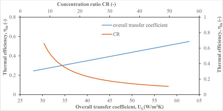
Nnamchi et al., Cogent Engineering (2020), 7: 1793453
https://doi.org/10.1080/23311916.2020.1793453
Figure 2. Temperature gradi
ents and thermal fluxes across
the parabolic trough solar col
lector for the thermal analysis.
gth2 ¼ Qsol;ab;ab Qcv;abo gi Qr;abo gi Qcv;abo ti Qr;abo ti Qgain 9 gth2 ! 0;
� � � �
) gth2 ¼ ηopt Aabo þ τg αab Aabo G hcv;abo gi Aabo Tabo Tgi hr;abo gi Aabo Tabo Tgi
��
hcv;abo ti Aabo ðTabo Tti Þ hr;abo ti Aabo ðTabo Tti Þ hcv;abi hair Aabi Tabi 0:5 Thair;o þ Thair;i
9 gth2 ! 0
(20)
Also, the thermal balance on the parabolic trough collector (t) is represented in Equation (21)
provides the third independent thermal design equation in Equation (21)
gth3 ¼ Qcv;abo ti þ Qr;abo ti þ Qr;gi ti Qcv;to a Qr;to sky 9 gth3 ! 0;
�
) gth3 ¼ hcv;abo ti Aabo ðTabo Tti Þ þ hr;abo ti Aabo ðTabo Tti Þ þ hr;gi ti Agi Tgi Tti (21)
�
hcv;to a Ato ðTto Ta Þ hr;to sky Ato Tto Tsky 9 gth3 ! 0
Page 10 of 30Nnamchi et al., Cogent Engineering (2020), 7: 1793453
https://doi.org/10.1080/23311916.2020.1793453
Adding Equations (19) and (21) or summing the thermal power functions; gth1 and gth3 gives the
fourth independent thermal design equation in Equation (22)
� � �
gth4 ¼ αg Ag G þ hcv;abo gi Aabo Tabo Tgi þ hr;abo gi Aabo Tabo Tgi hcv;go a Ago Tgo Ta
�
hr;go sky Ago Tgo Tsky þ hcv;abo ti Aabo ðTabo Tti Þ þ hr;abo ti Aabo ðTabo Tti Þ
�
hcv;to a Ato ðTto Ta Þ hr;to sky Ato Tto Tsky 9 gth4 ! 0
(22)
Hypothetically considering the equality of thermal conduction and convection on the absorber and
heat transfer fluid, respectively, gives the fifth independent thermal design equation in Equation (23)
� �
Tabo Tabi ��
gth5 ¼ kab Ac;ab hcv;abi air;i Aabi Tabi 0:5 Thair;o þ Thair;i 9 gth5
δab
!0 (23)
Pertinently, subtracting Equation (23) from Equation (20) or thermal power function gth5 from gth2
yields the sixth independent thermal design equation in Equation (24)
� � � �
gth6 ¼ ηopt Aabo þ τg αab Aabo G hcv;abo gi Aabo Tabo Tgi hr;abo gi Aabo Tabo Tgi
� �
Tabo Tabi
hcv;abo ti Aabo ðTabo Tti Þ hr;abo ti Aabo ðTabo Tti Þ kab Ac;ab 9 gth6 ! 0
δab
(24)
Also, considering the effectiveness of the absorber, the seventh independent thermal design
equation is obtained in Equation (25)
gth7 ¼ Qsol;ab;ab ΦQu 9 gth7 ! 0;
� � � � �� ��
gth7 ¼ ηopt Aabo þ τg αab Aabo G Φ ρair cpair ublower 0:25πd2abi n δfin 2lfin þ bfin Thair;o Thair;i 9 gth7 ! 0
0 !1
� 1010:13412 0:03977 Thair;o
� � B 1:6843 0:0015 Thair;o 2 C
B þ0:000105 Thair;o C
gth7 ¼ ηopt Aabo þ τg αab Aabo G ΦB C 9 gth7 ! 0
@ � �� � A
�ublower 0:25πd2abi n δfin 2lfin þ bfin Thair;o Thair;i
(25)
where Φð Þ � 1:0 is the effectiveness of the absorber, ρair (kg/m3) is the density of air, cpair (kJ/kg) is
the specific heat capacity of air, ui (m/s) is internal air velocity, n (-) is the number of rectangular
fins, δfin (m) is the thickness of the fins, lfin (m) is the length of the fins and wfin (m) is the width of
the fins. The variables in Equations (19) to (25) are defined as follows:
�
The outer surface area of the air-solar-finned absorber pipe, Aabo m2 in Equation (26) is
computed as
Aabo ¼ 2πr abo lpt ¼ πdabo lpt (26)
�
The inner surface area of the air-solar-finned absorber pipe, Aabi m2 in Equation (27) is deter
mined as
Aabi ¼ 2πrabi lpt ¼ πdabi lpt (27)
2
�
The cross-sectional area of the air-solar-finned absorber, Ac;ab m available to conduction is
designed in Equation (28) as
Page 11 of 30Nnamchi et al., Cogent Engineering (2020), 7: 1793453
https://doi.org/10.1080/23311916.2020.1793453
π� 2 � π
Ac;ab ¼ d d2abi ¼ ðdabo þ dabi Þðdabo dabi Þ (28)
4 abo 4
� �
The outer and inner surface areas of the glass cover (glaze) Ago m2 andAgi m2 , respectively, are
geometrically defined in Equation (29) as
Ago ¼ Agi ¼ wpt � lpt (29)
�
The inner surface area of the parabolic trough collector, Ati m2 is given in Equation (30) as
0 !0:5 0 !0:5 11
� � � �2
wpt 4hpt 2 4hpt 4hpt
Ati ¼ spt lpt ¼ @ þ1 þ 2fpt ln@ þ þ1 AA lpt
2 wpt wpt wpt
or (30)
0 !0:5 0 !0:5 11
� �2 � �2
wpt wpt wpt wpt
Ati ¼ spt lpt ¼ @ þ1 þ 2fpt ln@ þ þ1 AA lpt
2 4fpt 4fpt 4fpt
�
The outer surface area of the parabolic trough collector, Ato m2 is given in Equation (31) as
�� �
�2 �2 �0:5
� 0:5wpt þ f hpt þ δpt
Rpt þ δpt
Ato ¼ Ati ¼ � �2 �2 �0:5 spt lpt (31)
Rpt
0:5wpt þ f hpt
The convective heat transfer coefficient, hcv;go a between the outer glass (go) and ambient (a) is
expressed in Equation (32) as follows (Hammami et al., 2017; Nnamchi et al., 2020; Oko, 2011):
�0:5 � �
4:392773 uw;o lpt �
hcv;go a ¼ ¼ 4:392773 u0:5
w;o lpt
0:5
W=m2 K (32)
lpt
The radiative heat transfer coefficient, hr;go sk between the outer glass (go) and sky (sk) is given in
Equation (33) as (Kreith et al., 2000; Nnamchi et al., 2020; Oko, 2011)
� � �4 �
5:103 � 10 8 Tgo4
0:0552 � 2981:5
�
hr;go sk ¼ � � �� W=m2 K (33)
Tgo 0:0552 � 2981:5
The convective heat transfer coefficient, hcv;abo gi between the periphery of the absorber (abo) and
inner glass (gi) is specified in Equation (34) as (Ali & Sadek, 2018; Hammami et al., 2017; Nnamchi
et al., 2020; Rincón-Casado et al., 2017)
kair 1
hcv;abo gi � 0:54 Ralpt 4 ; 104 � Ralpt � 107 ;
lpt
� �� �
3 2
Ralpt ¼ lpt ρair cpair ðg cos ϕÞβabo gi Tabo Tgi =ðμair kair Þ; βabo gi ¼ 2= Tabo þ Tgi ;
2 � 3
l3pt ð2:1313 0:003Tair Þ2 1031:31 0:2047 Tair þ 0:00042 Tair 2
� (34)
4 � � � 5
ðg cos ϕÞ Tabo2þTgi Tabo Tgi
Ralab ¼ � �
1:03 � 10 6 þ7 � 10 8 Tair 4 � 10 11 Tair 2 0:0121eð0:0025 Tair Þ
Page 12 of 30Nnamchi et al., Cogent Engineering (2020), 7: 1793453
https://doi.org/10.1080/23311916.2020.1793453
The radiative coefficient, hr;abo gi between the periphery of the absorber (abo) and inner glass (gi)
is defined in Equation (35) as (Kreith et al., 2000; Nnamchi et al., 2020; Oko, 2011)
� �
4 4
σ Tabo Tgi
hr;abo gi ¼� � �
A
� �
1 εabo 1
εabo þ Fabo gi þFabo air
þ ε1gi 1 As;abo
s;gi
Tabo Tgi
� �
4 4
σ Tabo Tgi
¼� � � � (35)
1 εabo 1 1 πdabo lpt �
εabo þ þ εgi 1 wpt lpt Tabo Tgi
ðð12þ1πÞþð12 1πÞÞ
� �
4 4
σ Tabo Tgi �
) hr;abo gi ¼� � � � � W=m2 K
1 1
εabo þ εgi 1 πdwabo
pt
Tabo Tgi
The radiative coefficient, hr;gi ti between the inner; glass (gi) and parabolic trough collector (ti) and
is well defined in Equation (36) as (Kreith et al., 2000; Nnamchi et al., 2020; Oko, 2011).
Introduction to heat transfer: an algorithmic approach.
� �
σ Tgi4 Tti4
hr;gi ti ¼ �1 εgi
� � �
A �
1
εgi þ Fgi ti þFti ti
þ ε1ti 1 As;gi
s;ti
Tgi Tti
� �
σ Tgi4 Tti4
¼� � � � (36)
1 εgi 1 1 wpt lpt �
εgi þ þ εti 1 spt lpt Tgi Tti
ðð2πÞþð1 2πÞÞ
� �
σ Tgi4 Tti4 �
) hr;gi ti ¼� � � � � W=m2 K
1 1 w
εgi þ εti 1 sptpt Tgi Tti
The convective heat transfer coefficient, hcv;abo ti between the periphery of the absorber (abo) and
inner trough (ti) is empirically correlated in Equation (37) as (Ali & Sadek, 2018; Nnamchi et al.,
2020; Rincón-Casado et al., 2017)
kair 1
hcv;abo ti � 0:54 Ra4l ; 104 � Ralpt � 107 ;
ld pt
� �
3 2
Ralpt ¼ lpt ρair cpair ðg cos ϕÞβabo ti ðTabo Tti Þ =ðμair kair Þ;
Tair ¼ 0:5ðTabo þ Tti Þ; βabo ti ¼ 2=ðTabo þ Tti Þ;
2 � 3 (37)
l3pt ð2:1313 0:003Tair Þ2 1031:31 0:2047 Tair þ 0:00042 Tair 2
�
4 � � 5
2
ðg cos ϕÞ Tabo þTti ðTabo Tti Þ
Ralpt ¼ � �
1:03 � 10 6 þ7 � 10 8 Tair 4 � 10 11 Tair
2 0:0121eð0:0025 Tair Þ
The radiative heat transfer coefficient, hr;abo ti between the periphery of the air-solar-finned
absorber (abo) and the inner trough (ti) is given in Equation (38) as follows (Kreith et al., 2000;
Nnamchi et al., 2020; Oko, 2011):
Page 13 of 30Nnamchi et al., Cogent Engineering (2020), 7: 1793453
https://doi.org/10.1080/23311916.2020.1793453
� �
4
σ Tabo Tti4
hr;abo ti ¼� � �
A
�
1 εabo 1
εabo þ Fabo ti þFabo air
þ ε1ti 1 As;abo s;ti
ðTabo Tti Þ
� �
4
σ Tabo Tti4
¼� � � � (38)
1 εabo 1 πd l
εabo þ þ ε1gi 1 sptabolptpt ðTabo Tti Þ
ð12þ12Þ
� �
4 4
σ Tabo Tgi �
) hr;abo gi ¼� � � � W=m2 K
1 1
εabo þ εgi 1 πdsptabo ðTabo Tti Þ
The radiative coefficient, hr;abi hair between the inner absorber (abi) and hot air stream (hair) is
precisely defined in Equation (39) as (Ali & Sadek, 2018; Hammami et al., 2017; Nnamchi et al.,
2020)
0 114
ðcos ϕÞ�
0 2 1
B 426976:7297 655:4854153T hair;o þ 2:195492077T C
B hair;o C
B B 0:001293428T3 7 4
1:18125 � 10 10 Thair;o
5 CC
BB hair;o þ 2:748173 � 10 Thair;o CC
BB 2 C C
B @ þ2865:615635Tabi 5:216928875Thair;o Tabi þ 0:002771627Thair;o Tabi A C
B C
B 7 3 10 4
6:20037 � 10 Thair;o Tabi þ 2:3625 � 10 Thair;o Tabi C
B C
hcv;abi hair;o � 0:01996 labi0:25 e0:0009375Tfo B ! C
B 5
5:53265377 � 10 þ 3:37634802 � 10 Thair;o 7 C
B C
B 10 2
þ4:57651074 � 10 Thair;o 1:75614380 � 10 Thair;o 13 3 C
B C
B C
B C
B C
@ A
(39)
The convective heat transfer coefficient, hcv;to a between the periphery of the parabolic trough
collector (to) and the ambient (a) is obtained by considering the wind velocity to be one third
of its velocity in the windward direction according to (Nnamchi et al., 2020) Equation (40)
�0:5 � �
4:392773 0:33uw;o ld �
hcv;to a ¼ ¼ 2:523456 u0:5
w;o ld
0:5
W=m2 K (40)
ld
The radiative heat transfer coefficient, hr;to sk between the periphery of the parabolic trough
collector (to) and the sky (sk) is expressed in Equation (41) as (Kreith et al., 2000; Nnamchi et al.,
2020; Oko, 2011)
� � �4 �
4:536 � 10 8 Tto4 0:0552 � 2981:5
�
hr;to sk ¼ � � �� W=m2 K (41)
Tto 0:0552 � 2981:5
2.2.1. Simulation of thermal design equations
Similarly, the thermal design functions; gth1(W), gth2(W), gth3(W), gth4(W), gth5(W), gth6(W) and
gth7 are differentiated with respect to temperatures; Tgo(K), Tgi(K), Tabo(K), Tabi(K), Tti(K) and
Tto(K) and Thair (K), respectively, resulting in the simulatory matrices in Equation (42)
Page 14 of 30Nnamchi et al., Cogent Engineering (2020), 7: 1793453
https://doi.org/10.1080/23311916.2020.1793453
2 3
2 3 gth1
ΔTgo
6 7
2 @gth1 @gth1 @gth1 @gth1 @gth1 36 7 6 7
0 0 6 ΔTgi 7 6 gth2 7
@T @Tgi @Tabo @Tabi @Tti 6 7 6 7
6 go @gth2 @gth2 @gth2 @gth2 @gth2 7 6 7 6 7
6 0 0 7 6 7 6 7
6 @Tgi @Tabo @Tabi @Tti @Tair;o 76
ΔTabo 7 6 gth3 7
6 @gth3 @gth3 @gth3 @gth3 76 7 6 7
6 0 @Tgi @Tabo 0 @Tti @Tto 0 76 7 6 7
6 76 7 6 7
6 @gth4 gth4 7
6 @Tgo
@gth4
@Tgi
@gth4
@Tabo 0 @gth4
@Tti
@gth4
@Tto 0 7 76
6 ΔTabi 7 6
7¼6 7 (42)
6 76 7 6 7
6 0 0 @gth5 @gth5
0 0 @gth5 76 7 6 gth5 7
6 @Tabo @Tabi @Thair;o 76 ΔTti 7 6 7
6 @gth6 @gth6 @gth6 @gth6
76 7 6 7
6 0 0 0 7 6 7 6 7
4 @Tgi @Tabo @Tabi @Tti 56 7 6 gth6 7
@gth7 6 ΔTto 7 6 7
0 0 0 0 0 0 @Thair;o 4
6 7 6 7
5 6 7
4 gth7 5
ΔThair;o
Essentially, the thermal design procedure is akin to that of the optical design flowchart in
Figure 1 except that the thermal design variables are seven against the three optical design
variables.
Also, the detailed partial derivative of Equation (42) is given in the supplementary file. The
future values of the thermal design variables and the present values are defined in Equation
(43) as
Tk;iþ1 ¼ Tk;i þ ΔTk ; i ¼ 0; 1; 2; � � � ; N 1;
(43)
k ¼ f1; 2; 3; 4; 5; 6; 7g ¼ fgo; gi; abo; abi; ti; to; hairog
3
The final thermal design variables are established once the set convergent criterion (ζth ¼ 10 ) in
Equation (44) is attained
Tk;iþ1 Tk;i ¼ ζth ; i ¼ 0; 1; 2; � � � ; N 1;
(44)
k ¼ f1; 2; 3; 4; 5; 6; 7g ¼ fgo; gi; abo; abi; ti; to; hairog
In accordance with Abbood and Mohammed (2019), Macedo-Valencia (2014) and Alfelleg (2014)
the thermal efficiency of the air-solar-finned PTC, ηth (-) is stated in Equation (45) as
�
HTF output power m _ air cp air Tf ;o Tf ;i
ηthermal ¼ ¼ 9 Tf ;o ¼ Thair;o ; Tf ;i ¼ Thair;i (45)
Input Solar power Ag G
The overall collector efficiency in Equation (46) is approximated as the difference between the
attenuated optical and thermal efficiencies, which is in concordance with Mohamed (2013) find
ings (0.3649 ≤ ηcollector ≤ 0.5057)
� �
ηcollector � FR ηoptical ηthermal ¼ 0:90ð0:7193309 0:310727Þ � 0:44 (46)
2.3. Design of the air-solar-finned absorber
According to Nnamchi et al. (2020); the fin length, lf ðmÞ is expressed as a function of the outer
diameter of the air-solar-finned absorber in Equation (47)
lf ¼ 0:13588π dabo (47)
Also, Nnamchi et al. (2020) the fin width, wf ðmÞ designed as a function of the outer diameter of the
air-solar-finned absorber in Equation (48)
Page 15 of 30Nnamchi et al., Cogent Engineering (2020), 7: 1793453
https://doi.org/10.1080/23311916.2020.1793453
wf ¼ 0:0027 þ 0:0620836πdabo 0:0557077π2 d2abo (48)
In the same vein, the number of fins, nf ð Þ is related to the outer diameter of the air-solar-finned
absorber in Equation (49) according to Nnamchi et al. (2020) as
!
πdabo
nf ¼ 0:7117 þ 0:39525
0:0027 þ 0:0620836πdabo þ 0:0557077π2 d2abo
!2 (49)
πdabo
þ 0:0035 ; Integer ðnf Þ
0:0027 þ 0:0620836πdabo þ 0:0557077π2 d2abo
The design, formulation of the three facets of the designs (optical, thermal and fin) is covered in
Equations (1) to (49); the optimum design variables of the trio-designs on the specification of the
design input data are given in Equations (18), (44) and (46–49), respectively.
3. Results and discussion
The results comprise pertinent tables and informative graphs which are germane to discussion.
3.1. Results presentation
Apparently, some of input data were originated from the existing design data (Mohamed, 2013);
thus, they were not arbitrarily set. Moreover, the tradeoffs among the design variables guided in
the selection of the final design input data, which were subjected to an overall tradeoff in the
simulatory matrices (Equations (16 and 42)) leading to the final design variables.
Tables 1–5 inclusively contain the design input data and the output results; Precisely, Table 1
holds the input data for optical design equations (Equations (1)–(15)), Table 2 contains the input
data for thermal design equations (Equations (16)–(46)), Table 3 encompasses the physical char
acteristics of the PTSC, Tables 4 and 5 cover the simulated optical and thermal design variable
results. The output results were engaged in Equation (46) to determine the collector efficiency of
0.44 based on the slight obtuse-angled rim design.
Deeply, Figures 1–15 give insight into the design results by revealing the influence of design
variables on the key design parameters (optical efficiency, thermal efficiency, rim angle, and
concentration ratio). Sequentially, Figure 3 shows the dependency of optical efficiency on the
incidence angle and the design was pivoted on the minimum incidence angle. Figure 4 portrays
the reliance of optical efficiency on the rim angle and aperture. Figure 5 indicates the reliability of
optical efficiency on the aperture and the height of the trough. Figure 6 presents the dependence
of optical efficiency on the concentration ratio and absorber outer diameter. Figure 7 depicts the
sensitiveness of concentration ratio of the aperture and absorber sizes. Figure 8 describes the
Table 1. Input data to the optical design equations
S# Description Symbol Unit Value
1. The initial absorber tube outer diameter dabo (m) 0.0700
2. The initial focal distance fpt0 (m) 0.2502
3. The initial height of the trough hpt0 (m) 0.2897
4. The initial aperture of the trough wpt0 (m) 1.1997
5. The absorber length lab (m) 1.9800
6. Convergent factor of the optical design Equation (1) (gop1) Γ1 (-) 0.8269
7. Convergent factor of the optical design Equation (2) (gop2) Γ2 (-) 0.9530
8. Convergent factor of the optical design Equation (3) (gop3) Γ3 (-) 0.8271
Page 16 of 30Nnamchi et al., Cogent Engineering (2020), 7: 1793453
https://doi.org/10.1080/23311916.2020.1793453
Table 2. Input data to the thermal design equations
S# Description Symbol Unit Value
1. Intercept factor γ (-) 1.00
2. Incidence angle θi (-) 0.00
3. The absorptivity of glass αg (-) 0.0023
4. The emissivity of the inner trough εti (-) 0.25
5. The transmittance of the inner glass τg (-) 0.90
6. The absorptivity of the absorber εgi (-) 0.90
7. The emissivity of the outer absorber εabo (-) 0.23
8. The absorptance of the absorber tube αab (-) 0.90
9. The reflectance of absorber tube ρab (-) 0.38
10. The aperture of the trough wpt (m) 1.20
11. The height of the trough hpt (m) 0.279
12. The focal distance of the trough fpt (m) 0.254
13. The curve length of the trough spt (m) 1.667
14. The length of the trough lab (m) 1.20
15. The ratio of top to base velocity λb-t (-) 0.50
16. The initial outer temperature of the glass Tgo0 (K) 303.15
17. The initial inner temperature of the glass Tgi0 (K) 308.15
18. The initial outer temperature of the absorber tube Tabo0 (K) 408.15
19. The initial inner temperature of the absorber tube Tabi0 (K) 398.15
20. The initial inner temperature of the trough Tti0 (K) 303.15
21. The initial outer temperature of the trough Tto0 (K) 298.65
22. The initial outer temperature of the heat transfer fluid Thair,o0 (K) 363.15
23. The initial exit fluid temperature Tfo0 (K) 339.15
24. The ambient temperature Ta (K) 298.15
25. The sky temperature Tsk (K) 284.18
26. The wind speed, outside the PTSC uwo (m/s) 1.200
27. The wind speed inside the PTSC uwi (m) 0.400
28. Number of fins nf (-) 8.000
29. Width of the fins ωf (m) 0.0199
30. Length of the fins lf (m) 0.030
31. The thickness of the absorber δab (m) 0.0010
32. The thickness of the fin δf (m) 0.0005
33. Thermal conductivity of the absorber kab (W/mK) 0.163
Solar irradiance G (W/m2) 740.15
34. Thermal conductivity of the HTF kair (W/mK) 0.012
35. Convergent factor in the thermal design Equation (1) (gth1) Ψ1 (-) 0.0383
35. Convergent factor in the thermal design Equation (2) (gth2) Ψ2 (-) 0.0357
37. Convergent factor in the thermal design Equation (3) (gth3) Ψ3 (-) 0.0215
38. Convergent factor in the thermal design Equation (4) (gth4) Ψ4 (-) 0.0853
39. Convergent factor in the thermal design Equation (5) (gth5) Ψ5 (-) 0.9075
40. Convergent factor in the thermal design Equation (6) (gth6) Ψ6 (-) 0.0922
41. Convergent factor in the thermal design Equation (7) (gth7) Ψ7 (-) 0.0853
Page 17 of 30Nnamchi et al., Cogent Engineering (2020), 7: 1793453
https://doi.org/10.1080/23311916.2020.1793453
Table 3. Physical characteristics of the parabolic trough solar collector (PTSC)
S# Description Symbol Unit Value
1. The radius of curvature, Rpt(m) (m) 0.667
2. The internal surface area of the parabolic trough collector As,pt (m2) 2.456
3. The rim angle of the PTSC ψr (degree) 94
4. The effective geometrical concentration ratio, CR (-) 17
5. The optical efficiency, ηopt (-) 0.719
6. The end loss χend (-) 1.000
7. The incidence angle modifier, κ(θi) (-) 1.000
2
8. The outer surface area of the absorber pipe, Aabo (m ) 0.2640
9. The inner surface area of the absorber pipe, Aabi ðm2 Þ Aabi (m2) 0.257
10. The cross sectional area of the absorber, Ac;ab (m2) 0.00022
2
11. The outer surface areas of the glass cover (glaze Ago (m ) 1.206
12. The inner surface areas of the glass cover (glaze) and Agi (m2) 0.256
13. The inner surface area of the parabolic trough collector, Ati (m2) 2.000
2
14. The outer surface area of the parabolic trough collector, Ato (m ) 2.134
Table 4. The simulated results of the optical design variables
Optical geometry Net power function
Iteration, i fpt hpt wpt gopt1 gopt2 gopt3
(m) (m) (m) (W) (W) (W)
0 0.2502 0.2897 1.1997 1.420E-08 1.6587E-08 −4.7459E-06
1 0.2505 0.2891 1.1992 1.420E-08 3.7311E-08 −9.4940E-06
2 0.2511 0.2878 1.1980 1.420E-08 9.1185E-08 −1.8997E-05
3 0.2524 0.2851 1.1955 1.420E-08 2.4869E-07 −3.8030E-05
4 0.2552 0.2791 1.1898 1.420E-08 7.6326E-07 −7.6203E-05
5 0.2552 0.2791 1.1898 1.108E-09 1.4902E-04 −4.6102E-05
dependency of rim angle on the focal distance and height of the trough. Figure 9 exhibits the
responsiveness of rim angle on the aperture and focal distance. Figure 10 shows the sensitivity of
thermal efficiency on the solar irradiance and aperture area.
Figure 11 displays the susceptibility of thermal efficiency on the exit fluid temperature and inlet
fluid temperature; Figure 12 explains the susceptibleness of thermal efficiency on the absorber
inner diameter and HTF velocity; Figure 13 expounds the response of exit fluid temperature on the
solar irradiance and aperture area; Figure 14 explains the reaction of exit fluid temperature on the
HTF velocity and absorber diameter and lastly, Figure 15 shows the dependency of thermal
efficiency on the overall heat transfer coefficient and the concentration ratio.
The main objective of every design is to increase the efficiency or performance of the systems.
Individually, Figures 3–15 give a clearer picture on how to achieve the premium values of the four
design parameters (optical efficiency, thermal efficiency, rim angle, and concentration ratio).
Clearly, Figure 3 shows that the maximum optical efficiency (0.719355) could be attained when
the incidence angle, which is the angle between the sun ray and normal from the trough is zero;
thus, the slight obtuse angle rim design of the present work was carried out at zero incidence
angle which coincides with 12:00noon.
Page 18 of 30Nnamchi et al., Cogent Engineering (2020), 7: 1793453
https://doi.org/10.1080/23311916.2020.1793453
Table 5. The simulated results of the thermal design variables
Thermal design variables
i Tgo Tgi Tabo Tabi Thair,o Tti Tto
(K) (K) (K) (K) (K) (K) (K)
0. 305.15000 308.15000 418.15000 413.15000 408.15000 303.15000 299.65000
1. 305.15004 308.15000 418.14990 413.16438 408.15000 303.15021 299.65016
2. 305.14611 308.15000 418.14822 413.17717 408.15000 303.15329 299.64928
3. 305.12935 308.15000 418.14232 413.18574 408.15001 303.16402 299.65036
4. 305.12114 308.15237 418.13892 413.40484 408.16205 303.17051 299.64852
5. 305.12114 308.15237 418.13892 413.40484 408.16205 303.17051 299.64852
The corresponding thermal design functions
i gth1 gth2 gth3 gth4 gth5 gth6 gth7
(W) (W) (W) (W) (W) (W) (W)
0. 0.0003192 −0.0052588 0.0000928 0.0003107 −0.0004957 −0.0001592 0.0001910
1. 0.0003192 −0.0052588 0.0000928 0.0003107 −0.0004957 −0.0001592 0.0001910
2. −0.0001019 −0.0195252 −0.0125094 −0.0021633 −0.0004970 −0.0007241 0.0007472
3. 0.0587205 −0.0258267 −0.0260340 0.0497415 −0.0005020 −0.0012826 0.0019453
4. 0.0546539 −0.0621507 −0.0525982 0.0457129 −0.0068348 −0.0027437 0.0032894
5. 0.0546539 −0.0621507 −0.0525982 0.0457129 −0.0068348 −0.0027437 0.0032894
Figure 3. Dependency of optical
efficiency on the incidence
angle.
Vividly, Figure 4 indicates the ephemeral tradeoff between the aperture and rim angle in the
bid to maximize the optical efficiency. The intercept of the two curves may not be the true
balance until overall superposition is carried out. Similarly, Figure 5 presents a tentative tradeoff
between the aperture and the height of the trough in an attempt to maximize the optical
efficiency. Figure 6 presents a zero tradeoff between the absorber outer diameter and concen
tration ratio (the relative area of the aperture to the surface area of the absorber) in an
endeavour to optimize the optical efficiency. The step size change in Figure 6 indicates the
point at which further increment in both variables amounts to drastic drop in the optical
efficiency. Moreover, the transition points coincide with the design output variables. Alike,
Figure 7 depicts a momentary tradeoff between the aperture and the height of the trough (the
distance between the rim and the apex of the trough) in striving to enhance the concentration
ratio.
Page 19 of 30Nnamchi et al., Cogent Engineering (2020), 7: 1793453
https://doi.org/10.1080/23311916.2020.1793453
Figure 4. Reliance of optical
efficiency on the rim angle and
aperture.
Figure 5. Reliability of optical
efficiency on the aperture and
height of the trough.
Figure 6. Dependence of optical
efficiency on the concentration
ratio and absorber outer
diameter.
In the same vein, Figure 8 represents a brief tradeoff between the height of the trough and focal
distance (a point of convergence of infinite sun rays) in a stride to boost the rim angle. Likewise,
Figure 9 epitomizes a transitory tradeoff between the focal distance and aperture (the distance
Page 20 of 30Nnamchi et al., Cogent Engineering (2020), 7: 1793453
https://doi.org/10.1080/23311916.2020.1793453
Figure 7. Sensitiveness of con
centration ratio of the aperture
and absorber sizes.
between the rims) in an advance to increase the rim angle (the angle between the focal axis
and rim).
Contrarily, the design variables in Figures 10–14 absolutely lack tradeoff with respect to thermal
efficiency. Systematically, Figure 10 depicts the noncompeting and the inverse behaviour of
aperture area and solar irradiance with respect to thermal efficiency. The absence of equilibrium
in Figure 10 is because both variables form the denominator of the thermal efficiency and cannot
compete against each other.
Precisely, Figure 11 describes none competing and the apparent convergence behaviour of exit
fluid temperature and inlet fluid temperature with respect to thermal efficiency. The absence of
equilibrium in Figure 11is because both variables appear in the numerator of the thermal efficiency
and the inlet fluid temperature can never equalize the exit fluid temperature; otherwise, the
thermal efficiency becomes zero.
Specifically, Figure 12 designates none challenging and progressive behaviour of internal air
velocity and an absorber cross-section with respect to thermal efficiency. The absence of equili
brium in Figure 12 is because both variables form the numerator of the thermal efficiency and
cannot compete against each other.
Figure 8. Dependency of rim
angle to the focal distance and
height of the trough.
Page 21 of 30Nnamchi et al., Cogent Engineering (2020), 7: 1793453
https://doi.org/10.1080/23311916.2020.1793453
Figure 9. Responsiveness of rim
angle of the aperture and focal
distance.
Figure 10. Sensitivity of ther
mal efficiency on the solar
irradiance and aperture area.
Figure 11. Susceptibility of
thermal efficiency on the exit
fluid temperature and inlet
fluid temperature.
Page 22 of 30Nnamchi et al., Cogent Engineering (2020), 7: 1793453
https://doi.org/10.1080/23311916.2020.1793453
Figure 12. Susceptibleness of
thermal efficiency on the
absorber inner diameter and
HTF velocity.
Explicitly, Figure 13 defines none opposing and progressive behaviour of aperture area and solar
irradiance with respect to exit fluid temperature. The nonexistence of equilibrium in Figure 12 is
because both variables form the denominator of the thermal efficiency. Thus, they cannot com
pete against each other.
Similarly, Figure 14 expresses none contending and inverse behaviour of internal fluid velocity and
absorber cross-section with respect to exit fluid temperature. The absence of equilibrium in Figure 14
is because both variables form the denominator of the thermal efficiency. Thus, would not compete
against each other.
Contrarily, Figure 15 delineates a tradeoff between the overall heat transfer coefficient and
concentration ratio with respect to thermal efficiency. Hence, the emerging of equilibrium in
Figure 15 signifies that tradeoff sets in if the design variables are separated in the denominator
and the numerator of the objective function. Notably, the optical design and performance of
PTSC influence the thermal performance through the concentration ratio. Remarkably, high
concentration ratio diminishes the thermal efficiency and vice versa.
Collectively, the optimum values corresponding to the fleeting balance in Figures 3–5, 7–9 may
not hold as a result of internal conflicts or competition among the design variables leading to
Figure 13. Response of exit
fluid temperature on the solar
irradiance and aperture area.
Page 23 of 30Nnamchi et al., Cogent Engineering (2020), 7: 1793453
https://doi.org/10.1080/23311916.2020.1793453
Figure 14. Reaction of exit fluid
temperature on the HTF velo
city and absorber diameter.
Figure 15. The Effect of con
centration ratio and overall
heat transfer coefficient on the
thermal efficiency.
a final tradeoff among the design variables. Practically, the ultimate tradeoff among the design
variables is manoeuvred by the optical and thermal simulatory matrices at the point of conver
gence of each simulation. Pertinently, the design was made feasible by the introduction of optical
(Γs) and thermal Convergent factors (Ψs) in Tables 1 and 2, respectively.
3.1.1. Design input data
Tables 1–3 furnish the absolute input data required for both optical and thermal simulations in
Equations (16) and (42), respectively:
3.2. Discussion
Generally, the collector efficiency is dependent on the heat removal factor, the optical and thermal
efficiencies, it is worthy of noting that as the collector efficiency approaches the optical efficiency;
then, the thermal efficiency becomes insignificant and this phenomenon occurs. When the con
centration ratio is very high and the overall heat transfer coefficient (thermal conductance)
balances heat transport resistance. Thus, the obtuse-angled rim design ought to be developed
with a small rim angle such that the thermal component of the collector efficiency is preserved
and the exit fluid temperature equally raised according to Mohamed (2013). Hence, caution must
Page 24 of 30Nnamchi et al., Cogent Engineering (2020), 7: 1793453
https://doi.org/10.1080/23311916.2020.1793453
be traded not to design at an extremely obtuse-angled rim. However, the obtuse-angled rim
design has the enablement to evacuate the absorber, by screens the absorber from the cooling
effect of the ambient air. Consequently, thermal loss is drastically minimized by this method of
design compared to the acute-angled and right-angled rim designs, which are exposed to the
ambient cooling resulting in immense thermal losses. However, with the enveloping of the absor
ber tube in the acute-angled rim design, the performance of the PTSC would be boosted. Although,
the high temperature achieved poses a great threat to the operation of the system like misalign
ment and the associated problems, which distort the optical performance and at large reduce the
collector performance.
Peculiarly, the right-angled rim design has its merits and demerits; the thermal efficiency may be
higher relative to obtuse angle rim angle design because the concentration ratio is smaller but the
thermal loss is more in the right-angled rim design since the absorber is partially screened from
the cooling effect of the surrounding air.
Thus, gaining high thermal efficiency automatically risks the optical and collector efficiencies of
a PTSC, which is the probable design outcome of the acute-angled rim design (AARD). Also, gaining
high collector efficiency is at the detriment of diminishing the thermal efficiency, this is a likely
design outcome of extreme obtuse-angled rim design (EORAD), which is characterized with high
concentration ratio. Notably, the right-angled rim design (RARD) seems to be suited midway AARD
and OARD, since it does not encourage the risk of neither optical nor thermal efficiencies. RARD
appears to be the most attractive in the design and development of future PTSC but with the pitfall
of appreciable thermal loss is inevitable.
Notwithstanding, the current design for slight OARD (SOARD) serves as an eye-opener to the
enterprising designers of PTSCs to know that they have two primary design variables in striking
balance between the optical and thermal efficiencies; these are the focal distance and the height
of the trough. Equal height of the trough and focal distance support RARD whereas having the
focal distance higher than the height of the trough supports AARD. Lastly, having the focal
distance less than the height of the trough encourages OARD.
Being aware of these intricate outcomes; the future designs should be rested on making, the
collector efficiency to be possibly half of the optical efficiency by selecting an appropriate focal distance
and the height of the trough. This work candidly recommends that slight obtuse-angled rim design
(SOARD) should not be in the excess of 5° ahead of RARD for the efficient performance of the PTSCs.
Furthermore, the present design gave a collector efficiency of 0.44 based on the slight obtuse-
angled rim design (94°), this collector efficiency compared well with those of Macedo-Valencia
et al. (2014) and Mohamed (2013) who designed at obtuse-angled rim of 96° and recorded
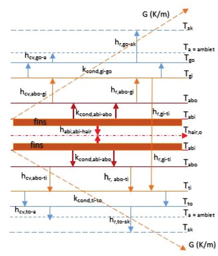
Figure 16. The isometric draw
ings of the reheating unit.
Page 25 of 30You can also read