Installation, commissioning and operating instructions - for stationary Fibre Nickel Cadmium Batteries grid | power FNC - Hoppecke
←
→
Page content transcription
If your browser does not render page correctly, please read the page content below
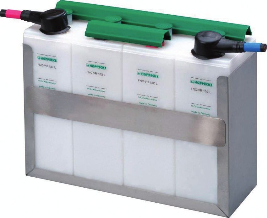
Installation, commissioning and operating instructions

  for stationary Fibre Nickel Cadmium Batteries grid | power FNC®

                                                    Similar to the illustration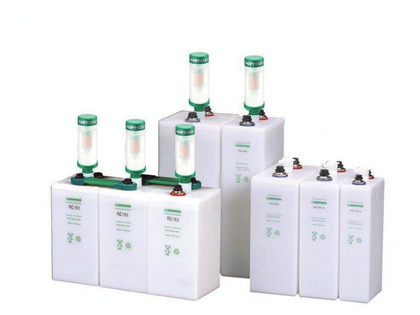
Foreword
                                                                                                                                                   Dear Customer,
                                                                                                                                                   Thank you very much for having decided in favour of a product bearing our brand name.
                                                                                                                                                   Please read this documentation carefully before working on the batteries or their components. It contains important
                                                                                                                                                   information on safe and proper unpacking, storage, installation, commissioning and on operation and maintenance
                                                                                                                                                   of grid | power FNC®-batteries.
                                                                                                                                                   Amendments to this documentation are subject to change without prior notice. Our products undergo continuous
                                                                                                                                                   advanced development. As a result, there may be deviations between the illustrations given in this documentation
                                                                                                                                                   and the purchased product. This installation manual is not covered by any change service.
                                                                                                                                                   Keep this documentation in such a manner that it is available immediately to all those who need to carry out work
                                                                                                                                                   in connection with the battery system or its components.

                                                                                                                                                   HOPPECKE
                                                                                                                                                   Batterie Systeme GmbH			                                          Service-Hotline Germany:
                                                                                                                                                   P.O. Box 11 80 			                                                0800 24677-32
                                                                                                                                                   D-59914 Brilon

                                                                                                                                                   Bontkirchener Straße 1 			                                        International Service-Hotline:
                                                                                                                                                   D-59929 Brilon-Hoppecke		                                         +49 (0)180 5229999
                                                                                                                                                   Phone      +49 (0)2963 61-1412
                                                                                                                                                   Fax        +49 (0)2963 61-1452
                                                                                                                                                   Internet   www.hoppecke.com
                                                                                                                                                   Email      hbs@hoppecke.com

Installation, commissioning and operating instructions
for stationary Fibre Nickel Cadmium Batteries grid | power FNC®

Type, Design, Print: PRIOTEX Medien GmbH, 59609 Anröchte

© 2021     HOPPECKE Batterien GmbH & Co. KG
           P.O. Box 11 40
           D-59914 Brilon

All rights reserved, even for patent and utility patent applications.
The distribution and duplication of this document and the use and disclosure of its contents are prohibited
unless written permission is granted by HOPPECKE Batterien GmbH & Co. KG. Noncompliance will result in a
claim for damages.

                          Installation, commissioning and operating instructions for stationary Fibre Nickel Cadmium Batteries grid | power FNC®    Installation, commissioning and operating instructions for stationary Fibre Nickel Cadmium Batteries grid | power FNC®
                          V1.0 (01.2021)                                                                                                                                                                                                                  V1.0 (01.2021)

2                                                                                                                                                                                                                                                                            3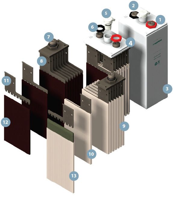
Table of Contents

1 Using this manual............................................................................................................................................................. 6               8.1.5.            Ventilation Requirements��������������������������������������������������������������������������������������������������������������������������� 23
  1.1.       Target group of this document����������������������������������������������������������������������������������������������������������������������6                               8.2.              Installing the Battery System��������������������������������������������������������������������������������������������������������������������� 24
  1.2.       Means of Representation������������������������������������������������������������������������������������������������������������������������������6                             8.2.1.            Preliminary Work on Unfilled and Uncharged grid | power FNC®-cells���������������������������������������������������� 24
  1.3.       Notation of Nominal Data������������������������������������������������������������������������������������������������������������������������������7                            8.2.2.            Equipping the Rack or Cabinet������������������������������������������������������������������������������������������������������������������ 25
  1.4.       Abbreviations and Definitions�����������������������������������������������������������������������������������������������������������������������7                              8.2.3.            Connecting the Battery System������������������������������������������������������������������������������������������������������������������ 25
                                                                                                                                                                                                 8.2.4.            Labelling the Battery System��������������������������������������������������������������������������������������������������������������������� 27
2 Safety���������������������������������������������������������������������������������������������������������������������������������������������������������������������������������8
  2.1.           General Safety Instructions���������������������������������������������������������������������������������������������������������������������������8                     9 Commissioning��������������������������������������������������������������������������������������������������������������������������������������������������������������� 27
  2.2.           Personal Protective Equipment���������������������������������������������������������������������������������������������������������������������9                           9.1.     Charging Procedures for the Initial Commissioning��������������������������������������������������������������������������������� 28
  2.3.           Specific Safety Instructions for grid | power FNC®-Battery Systems����������������������������������������������������������9                                                 9.1.1.   Charging with Constant Current����������������������������������������������������������������������������������������������������������������� 28
  2.3.1.         Safety Instructions on Handling with Electrolyte�����������������������������������������������������������������������������������������9                                    9.1.2.   Charging with Constant Current and Constant Voltage (CCCV)��������������������������������������������������������������� 29
  2.3.2.         Safety Instructions on Charging the Battery System�������������������������������������������������������������������������������� 10                                         9.2. 	Commissioning of Unfilled and Uncharged (UU) and Filled and uncharged (FU)
  2.3.3.         Protection against dangerous body contact currents������������������������������������������������������������������������������ 10                                                    grid | power FNC®-cells������������������������������������������������������������������������������������������������������������������������������� 30
  2.3.4.         Special hazards in the event of fire����������������������������������������������������������������������������������������������������������� 11                            9.3.     Commissioning Filled and Charged (FC) FNC®-cells��������������������������������������������������������������������������������� 31
                                                                                                                                                                                                9.4.     Capacity Testing of Batteries According to DIN IEC 60623��������������������������������������������������������������������� 32
3 Intended/Unintended use.............................................................................................................................................. 11
  3.1.      Intended Use����������������������������������������������������������������������������������������������������������������������������������������������� 11                   10 Maintenance���������������������������������������������������������������������������������������������������������������������������������������������������������������� 32
  3.2.      Unintended Use������������������������������������������������������������������������������������������������������������������������������������������� 11                       10.1.    Checking for Cleanliness and Condition of the Battery System�������������������������������������������������������������� 33
                                                                                                                                                                                                10.2.    Checking the Electrolyte Levels����������������������������������������������������������������������������������������������������������������� 34
4 Directives, Legislation and Standards.......................................................................................................................... 12                            10.3.    Measuring the Charging Voltage���������������������������������������������������������������������������������������������������������������� 36
                                                                                                                                                                                                10.4.    Testing the Insulation Resistance�������������������������������������������������������������������������������������������������������������� 36
5 Product description........................................................................................................................................................ 12                10.5.    Cleaning������������������������������������������������������������������������������������������������������������������������������������������������������� 37
  5.1.      grid | power FNC®-cell.................................................................................................................................. 12                         10.6.    Fill up the Electrolyte Level with Distilled Water��������������������������������������������������������������������������������������� 37
  5.2.      Cell Plugs for Different Use Cases������������������������������������������������������������������������������������������������������������� 14                                 10.7.    Reconditioning��������������������������������������������������������������������������������������������������������������������������������������������� 39
  5.3.      Operation Modes (see also IEC 62485-2)������������������������������������������������������������������������������������������������ 14
  5.3.1.    Standby parallel operation������������������������������������������������������������������������������������������������������������������������� 14                           11 Troubleshooting����������������������������������������������������������������������������������������������������������������������������������������������������������� 42
  5.3.2.    Buffer operation������������������������������������������������������������������������������������������������������������������������������������������ 15                      11.1.     Over Consumption of Distilled Water�������������������������������������������������������������������������������������������������������� 42
  5.3.3.    Switching mode (charge/discharge mode)����������������������������������������������������������������������������������������������� 15                                           11.2.     Dispersion of the Individual Cell Voltages������������������������������������������������������������������������������������������������� 42
  5.4.      Battery Charging Characteristic����������������������������������������������������������������������������������������������������������������� 16                                11.3.     Available Battery Capacity is Low�������������������������������������������������������������������������������������������������������������� 42
  5.5.      Battery Capacity������������������������������������������������������������������������������������������������������������������������������������������ 17                      11.4.     Insulation Resistance is Low���������������������������������������������������������������������������������������������������������������������� 43
                                                                                                                                                                                                11.5.     Battery Voltage not Measureable�������������������������������������������������������������������������������������������������������������� 43
6 Transport������������������������������������������������������������������������������������������������������������������������������������������������������������������������� 18
  6.1.        Surface Transport (Road/Rail) according to ADR/RID����������������������������������������������������������������������������� 18                                             12 Disassembly, Disposal and Recycling........................................................................................................................ 43
  6.2.        Transport by sea according to the IMDG Code����������������������������������������������������������������������������������������� 19
  6.3.        Air Freight����������������������������������������������������������������������������������������������������������������������������������������������������� 19            13 Appendix����������������������������������������������������������������������������������������������������������������������������������������������������������������������� 44
  6.4.        Checking the delivery���������������������������������������������������������������������������������������������������������������������������������� 20                       13.1.     Commissioning Record������������������������������������������������������������������������������������������������������������������������������� 44
                                                                                                                                                                                                13.2.     Maintenance Log����������������������������������������������������������������������������������������������������������������������������������������� 47
7 Storage���������������������������������������������������������������������������������������������������������������������������������������������������������������������������� 20       13.2.1.   Six-monthly Maintenance Interval������������������������������������������������������������������������������������������������������������� 48
  7.1.         Storage of Filled and Charged (FC) Cells��������������������������������������������������������������������������������������������������� 21                                  13.2.1.1. Visual Inspection and Checking Electrolyte Level������������������������������������������������������������������������������������ 48
  7.2.         Storage of Unfilled and Uncharged (UU) and Filled and Uncharged (FU) grid | power FNC®-cells������� 21                                                                          13.2.1.2. Measuring battery system voltage������������������������������������������������������������������������������������������������������������� 49
                                                                                                                                                                                                13.2.2.   Annual Maintenance Interval��������������������������������������������������������������������������������������������������������������������� 50
8 Installation���������������������������������������������������������������������������������������������������������������������������������������������������������������������� 22        13.2.2.1. Cleaning the battery system ���������������������������������������������������������������������������������������������������������������������� 50
  8.1.        Mounting a Rack or Cabinet����������������������������������������������������������������������������������������������������������������������� 22                             13.2.2.2. Insulation testing����������������������������������������������������������������������������������������������������������������������������������������� 51
  8.1.1.      Before Mounting a Rack or Cab����������������������������������������������������������������������������������������������������������������� 22                                13.2.2.3. Filling up distilled water������������������������������������������������������������������������������������������������������������������������������ 52
  8.1.2.      Checking the Scope of Delivery����������������������������������������������������������������������������������������������������������������� 22                               13.2.3.   Maintenance Interval every 5 years���������������������������������������������������������������������������������������������������������� 52
  8.1.3.      Mounting a Rack����������������������������������������������������������������������������������������������������������������������������������������� 23                      13.2.3.1. Reconditioning��������������������������������������������������������������������������������������������������������������������������������������������� 52
  8.1.4.      Mounting a Cabinet������������������������������������������������������������������������������������������������������������������������������������� 23                       13.2.3.2. Measuring of Single Cell Voltages������������������������������������������������������������������������������������������������������������� 53
                                                                                                                                                                                                13.3.     Useful tools�������������������������������������������������������������������������������������������������������������������������������������������������� 55

                                             Installation, commissioning and operating instructions for stationary Fibre Nickel Cadmium Batteries grid | power FNC®                             Installation, commissioning and operating instructions for stationary Fibre Nickel Cadmium Batteries grid | power FNC®
                                             V1.0 (01.2021)                                                                                                                                                                                                                                           V1.0 (01.2021)

4                                                                                                                                                                                                                                                                                                                                                                                5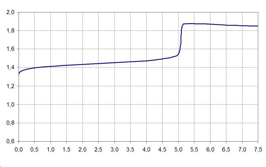
1 Using this manual 1.3 Notation of Nominal Data
This operating and installation manual is intended to assist with the optimal operation of the HOPPECKE nickel- Nominal battery data is used in accordance with the following notation in this operation and installation manual:
cadmium batteries used, as well as their installation and maintenance. This is the only way in which a maximum
service life can be achieved.
Notation Meaning Value
Please contact your local authorised dealer:
Un Nominal voltage 1.2 V multiplied by the number of cells connected in series
– If you have any queries on this documentation.
– If there are local regulations or provisions that are not covered by this documentation or are contrary to its contents. C5
Cn Nominal capacity available capacity at discharge at I5 (see nameplate) up to 1.0 V
for each cell connected in series at nominal temperature
1.1 Target group of this document In Nominal current I5 (see nameplate) = Cn/5 h
All work on the battery system and the grid | power FNC -cells must only be carried out by trained, fully qualified
® Nominal
Tn 20 °C
and authorised personnel: temperature
– Personnel trained by HOPPECKE
– HOPPECKE experts 1.4 Abbreviations and Definitions
The following table explains abbreviations and terms used in these installation, commissioning and operating
1.2 Means of Representation instruction:
The following icons and signal words are used in this operating and installation manual:
Abbreviation/Definition Explanation
Denotes an immediate hazard with a high level of risk that could lead to death or severe physical Describes the defined discharge and subsequent charging of the battery with
injury if it is not prevented. Reconditioning constant current. This allows the capacity losses of the battery system to be
eliminated or reduced.
Danger!
The charge of an accumulator to compensate for its self-discharge with the aim
Float Charging
of keeping the accumulator fully charged.
Denotes a potential hazard with a medium level of risk that could lead to death or severe physical Indicates the charging of an accumulator with increased voltage and a defined
Boost Charging
injury if it is not prevented. current in order to fully charge the accumulator as quickly as possible.
grid | power FNC®-batteries are NiCd batteries and contain potassium hydroxide
Warning! (KOH) as electrolyte with an addition of lithium hydroxide (LiOH). When handled
Electrolyte
properly, grid | power FNC®-batteries are safe. Contact with the electrolyte is
excluded.
Denotes a hazard with a low level of risk that could lead to minor or medium degree of physical injury
if it is not prevented.
Caution!
Denotes a hazard in which the product, other objects or the environment may get damaged if it is
not prevented.
Attention!
Denotes first-aid measures.
Denotes important instructions to make best use of the product.
Installation, commissioning and operating instructions for stationary Fibre Nickel Cadmium Batteries grid | power FNC® Installation, commissioning and operating instructions for stationary Fibre Nickel Cadmium Batteries grid | power FNC®
V1.0 (01.2021) V1.0 (01.2021)
6 7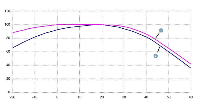
2 Safety 2.2 Personal Protective Equipment
Observe the safety instructions while handling the battery system and its components. Always wear the following personal protective equipment when working on the batteries or their components:
– Safety glasses
– Safety gloves
2.1 General Safety Instructions – Protective clothing, preferably made of cotton to prevent the development of electrostatic charge on clothes and
the body
Caused by:
– Safety boots
– Explosions
In this way, you can prevent or at least mitigate injuries in the event of an accident.
– Pressure waves
Danger! – Flying hot or molten substances The conductivity of textiles and shoes must have the following characteristics to prevent electrostatic charge:
– an insulation resistance ≥ 105 Ω
Avoid:
– a surface resistance < 108 Ω
– Short-circuits
– Electrostatic charges and discharges
– Sparking or arcs 2.3 Specific Safety Instructions for grid | power FNC®-Battery Systems
2.3.1 Safety Instructions on Handling with Electrolyte
Caused by:
grid | power FNC®-cells are NiCd batteries and contain caustic potassium hydroxide solution as electrolyte.
– Voltages
Danger! – Electric shocks Contact with the electrolyte can occur if you work on open cells. Electrolyte can be discharged if the
housing of an grid | power FNC®-cell is damaged. It can cause severe burn injuries on the skin and
Metallic parts of the batteries are always live. High current flow occurs if there is a short-circuit. to the eyes.
– Please be very careful when doing any work on the batteries in order to prevent severe injuries Warning! Wear safety glasses and safety gloves when working on the battery system.
caused by electrical shocks or burns.
– Never place tools or other metallic objects on a battery.
– Remove watches and jewellery before doing any work on the batteries. First-aid measures
– Do not touch any exposed battery parts, connectors, terminals or poles. Take the following actions if you have come into contact with the electrolyte:
Electrolyte solution on the skin or in the hair
Reverse polarity of batteries or cells can cause overheating and thereby result in the electrolyte being – Dab it with a cotton or paper-based cloth, but do not wipe it off.
ejected from the cell vents. Check for correct polarity before making connections. – Remove pieces of clothing that have been contaminated, and while doing so, avoid contact with the
affected parts of the body as far as possible.
Danger!
– Rinse off the affected parts for a longer period of time under flowing water.
Electrolyte in the eyes
The cells of the batteries contain more than 0.1 % cadmium by weight:
– Gently rinse off the eye for up to 15 minutes with an eyewash or wash the eye in flowing water.
– Symbol: Cd Avoid excessive water pressure when doing so. Remove any contact lens as far as possible and
Attention! – CAS number: 7440-43-9 continue to rinse off the eye.
– Consult an eye specialist or physician immediately.
Electrolyte in the mouth
– Rinse the mouth with water. DO NOT induce vomiting.
– Contact a doctor immediately or look for a hospital.
Use water to wash off clothes contaminated with electrolyte.
Installation, commissioning and operating instructions for stationary Fibre Nickel Cadmium Batteries grid | power FNC® Installation, commissioning and operating instructions for stationary Fibre Nickel Cadmium Batteries grid | power FNC®
V1.0 (01.2021) V1.0 (01.2021)
8 9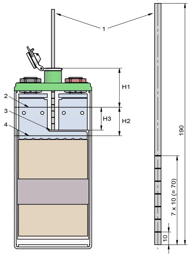
2.3.2 Safety Instructions on Charging the Battery System                                                                                             2.3.4 Special hazards in the event of fire

              Danger of explosion due to formation of oxyhydrogen gas!                                                                                                 – Wear personal protective equipment against alkaline solutions (2.2 Personal Protective Equipment
              When the cells are charged, water is decomposed and a hydrogen-oxygen-gas mixture (oxyhydrogen                                                              on page 9), for large battery systems also use breathing protection with self-sufficient breathing
              gas) is formed, which already explodes with low energy input.                                                                                               air supply.
 Danger!                                                                                                                                              Danger!          – Disconnect battery electrically.
              Keep any source ignition away from the battery system:                                                                                                   – Extinguish incipient fires with CO2.
              – Open flames or fire                                                                                                                                    – When extinguishing electric fires with water in low-voltage systems (up to 1 kV), maintain a spray
              – Smoking                                                                                                                                                   distance of 1 m and a full spray distance of 5 m.
              – Glowing embers                                                                                                                                         – Wear alkali-resistant protective clothing! In case of contact with water, there is a risk of reactions
              – Flying sparks during grinding work                                                                                                                        with the electrolyte (caustic solution) and consequently of violent spraying.
              – Electrical sparks caused by switches or fuses                                                                                                          – Extinguish in short intervals. Otherwise, there is danger of explosion due to possible static charging
              – Hot surfaces with temperature above 300 °C                                                                                                                on the battery housing.
              – Electrostatic discharges                                                                                                                               Failure to do so may result in death or serious injury.

              Work with electrically insulated tools that do not strike sparks. Ground yourself when working directly
              on the battery system.
              Make sure that there is adequate ventilation in the container room in accordance with IEC 62485-2,                                     3 Intended/Unintended Use
              so that the potential explosive gas mixture is discharged.
                                                                                                                                                     3.1 Intended Use

              The following instructions are meant to prevent explosions caused by electrostatic discharges                                          The grid | power FNC®-cells of the battery system are used to store and release electrical energy in standby
              (Source: ZVEI – German Electrical and Electronic Manufacturers‘ Association – Professional                                             applications, for example, uninterruptible power supply.
              Association for Batteries):
              – Do not rub batteries with a plastic housing with a dry cloth or one made of synthetic material!                                     Intended use includes the following requirements:
                 Rubbing plastic surfaces generates electrostatic charge. Clean the batteries only with a cotton                                     – Operating the battery system only if it is in proper condition
                 cloth moistened in water. Wiping with a cotton cloth moistened in water does not generate                                           – No deactivation or disassembly of safety devices
                 electrostatic charge.
                                                                                                                                                     – Compliance with all instructions given in this operating and installation manual
              – Do not rub batteries with clothing e. g. made of cotton! This can generate electrostatic charge.
              – Wear shoes and clothes that prevent the formation of electrostatic charge on account of their
                 special surface resistance (see chapter 2.2 Personal Protective Equipment on page 9).                                               3.2 Unintended Use
              – Use hand-held lamps with a mains cable without a switch (Protection class II) or hand-held lamps
                 with a battery (Protection class IP54).                                                                                                               Unintended use of the batteries can lead to personal injuries or damage to property.
              – Moisten a label of a battery (with water) before you pull off a label. Pulling off plastic labels can                                                 In case of unintended use, HOPPECKE Batterie Systeme GmbH shall not assume any liability for
                 develop electrostatic charge.                                                                                                                         personal injuries or damage to property that result directly or indirectly from handling the batteries.
                                                                                                                                                      Danger!          The operator shall be solely responsible for the risks arising from unintended use.

2.3.3 Protection against dangerous body contact currents                                                                                             Any other use than described under “Intended use” is not intended and therefore not permitted.

In stationary battery installations, measures must be taken to guard against direct and indirect contact. For battery                                The unintended use of the product includes in particular:
installations this protection can take the form of obstacles or distance.                                                                            – Operation in explosion-endangered areas
                                                                                                                                                     – Operation in safety-relevant applications, unless these applications are expressly specified or permitted in the
According to IEC 62485-2:
                                                                                                                                                        product documentation
– Battery installations with a rated voltage of 60 V … 120 V must be accommodated in electrical operation areas.
                                                                                                                                                     – Operation without permanent/insufficient fastening
– Battery installations with a rated voltage of more than 120 V must be accommodated in enclosed, electrical
                                                                                                                                                     – Operation outside the technical data
   operating areas.
                                                                                                                                                     – Operation or storage outside the specified environmental conditions
Doors of battery rooms and cubicles count as obstacles when they are identified by the following warning plates                                      – The electrical connection does not correspond to the documentation supplied with the battery
(fitted externally):
– Warning plate “Dangerous Voltage”, if the battery voltage exceeds 60 V (see ISO 3864).
– Prohibition sign: “No fire, naked flame or smoking”.
– Warning plate “Battery Room” to indicate electrolyte, explosive gases, dangerous voltages and currents.

                            Installation, commissioning and operating instructions for stationary Fibre Nickel Cadmium Batteries grid | power FNC®    Installation, commissioning and operating instructions for stationary Fibre Nickel Cadmium Batteries grid | power FNC®
                            V1.0 (01.2021)                                                                                                                                                                                                                  V1.0 (01.2021)

10                                                                                                                                                                                                                                                                             11
4 Directives, Legislation and Standards                                                                                                               The following drawing shows the internal structure of a grid | power FNC®-cell:

Please observe the latest edition of the following rules and regulations:
– Accident prevention regulations, especially DGUV Regulation 1: Accident prevention regulation; Principles of
   prevention
– DIN EN ISO 20345 (“Personal safety gear – Safety boots”)
– DIN VDE 0105 (“Operation of electrical equipment”), in particular, governs the requirements for quality and                                                                                                                                1 = Positive pole
   qualification for working on electrical equipment (DIN VDE 0105-100)
                                                                                                                                                                                                                                              2 = Negative pole
– DIN VDE 100/IEC 60364 (“Erection of low-voltage installations”)
                                                                                                                                                                                                                                              3 = Cell casing
– DIN EN 50110/VDE 0105 (“Operation of electrical installations”)
                                                                                                                                                                                                                                              4 = Cell lid
– IEC 62485/VDE 0510 (“Safety requirements for secondary batteries and battery installations”), particularly
                                                                                                                                                                                                                                              5 = Vent plug
   applicable for calculating the air ventilation required in battery rooms (in IEC 62485-2)
                                                                                                                                                                                                                                              6 = Pole nut
– DIN EN 60623/IEC 60623 (“Secondary cells and batteries containing alkaline or other non-acid electrolytes.
   Vented nickel-cadmium prismatic rechargeable single cells”), applicable primarily to the testing of cells (type                                                                                                                            7 = Cell pole
   test, series production test and field test)                                                                                                                                                                                               8 = Negative electrode stack
– DIN EN 60993/IEC 60993 (“Electrolyte for vented nickel-cadmium cells”)                                                                                                                                                                      9 = Positive electrode stack
– DIN VDE 0100-600 Low-voltage electrical installations – Part 6: Verification (IEC 60364-6:2006, modified);                                                                                                                                10 = Positive fiber structure electrode
   German implementation HD 60364-6:2007                                                                                                                                                                                                     11 = Current tab
– ADR/RID: European Treaty on the international transport of hazardous goods by road/Ordinance on the inter-                                                                                                                                12 = Negative fiber structure electrode
   national transport of hazardous goods by rail                                                                                                                                                                                             13 = Separator
– IATA-DGR: Dangerous goods regulations – international air transport association. German: Gefahrgut-
   Bestimmungen – Internationale Flug-Transport-Vereinigung
– IMDG Code: International Maritime Code for Dangerous Goods, German: Gefahrgutkennzeichnung für gefähr-
   liche Güter im Seeschiffsverkehr
– Ordinance on the supervision of waste and residual materials (German Federal Law Gazette, 1996)
In addition, observe and follow all applicable territorial and national, corporate and project-specific regulations
and accident prevention regulations.
                                                                                                                                                      The electrolyte is a solution of potassium hydroxide (KOH) in distilled water with an addition of lithium hydroxide
                                                                                                                                                      (LiOH). The standard electrolyte is designed for use in temperatures of between -25 °C and +45 °C. The lithium
                                                                                                                                                      hydroxide in the electrolyte varies between the different cell types (X, H, M, L). DIN IEC 993 is valid for the production
                                                                                                                                                      of the electrolyte.
5 Product description
                                                                                                                                                      When the cells are in operation, the density of the standard electrolyte is 1.19 kg/l ± 0.01 kg/l at the reference
grid | power FNC®-cells are connected to form battery systems and are deployed in standby applications.
                                                                                                                                                      temperature of 20 °C (electrolyte density can be higher on delivery).
Here, they fulfil one or more of the following functions:
– Buffering and supply of the low-voltage networks                                                                                                                      The electrolyte density is no indicator for the state of charge of nickel cadmium batteries.
– Providing power in case of an emergency
– To start a standby gen set/engine
                                                                                                                                                      For most FNC®-products, HOPPECKE supplies on request a special electrolyte that allows operation in low tempe-
                                                                                                                                                      ratures down to -45 °C.
5.1 grid | power FNC®-cell

grid | power FNC®-cell are nickel-cadmium cells, which are produced with fiber structure technology. It uses an
extremely porous, three-dimensional synthetic fleece, metallized with nickel.

The particular characteristics are:
– The best volume/weight ratio by 90 % volume filling of the fiber electrodes with active material.
– High to very high values of current can flow during charging and discharging.
– No carbonates are formed in the electrolyte.
– The batteries have long service life and several charging cycles even under extreme temperature conditions.
– It withstands the most extreme of stress caused by shocks and vibrations.
– Cell housings made optionally either of polyether sulphone, polyamide or polypropylene.
– A large variety of constructions ranging from high and extremely flat to low with a large surface area.

                             Installation, commissioning and operating instructions for stationary Fibre Nickel Cadmium Batteries grid | power FNC®    Installation, commissioning and operating instructions for stationary Fibre Nickel Cadmium Batteries grid | power FNC®
                             V1.0 (01.2021)                                                                                                                                                                                                                  V1.0 (01.2021)

12                                                                                                                                                                                                                                                                                     13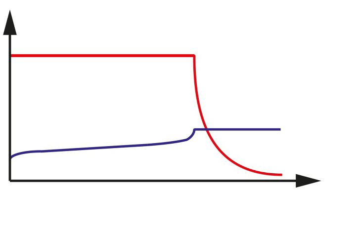
5.2 Cell Plugs for Different Use Cases                                                                                                                5.3.2 Buffer operation

     Cell Plug                                                           Description
                                                                                                                                                        Direct current source                                               Load

                   Yellow transport plug:
                   grid | power FNC®-cells are sealed with yellow transport plugs at delivery.

                                                                                                                                                                                              Battery

                   Vent plug:
                   The vent plug is the standard plug for FNC®-standby applications. It provides easy access to
                                                                                                                                                      Characteristics of this operating mode are:
                   control and refill the electrolyte level. The lid contains a filter that works as backfire protection.
                                                                                                                                                      – Load, direct current source and battery are permanently connected in parallel.
                                                                                                                                                      – The charging voltage is the operating voltage of the battery and at the same time the system voltage.
                                                                                                                                                      – The direct current source (charging rectifier) is not able to supply the maximum load current at all times. The load
                   Valve regulated plug (VR):                                                                                                            current temporarily exceeds the rated current of the DC source. During this time, the battery supplies current.
                   A low-pressure valve recombines oxygen and hydrogen gasses inside the cell with up to 90 %                                         – The battery is therefore not fully charged at all times.
                   efficiency.                                                                                                                        – The charging voltage to be set is 1.45 ... 1.55 V per cell x number of cells connected in series (measured at the
                   No water addition or filling is required over a 20 year service life when operated on float charge                                    end poles of the battery).
                   at 20 °C. Furthermore, the VR plug provides a backfire protection.

                                                                                                                                                      5.3.3 Switching mode (charge/discharge mode)
Furthermore, HOPPECKE provides grid | aquagen pro vent plugs that are described in a separate documentation.
Contact HOPPECKE for further information.

                                                                                                                                                        Direct current source                                               Load
5.3 Operation Modes (see also IEC 62485-2)

5.3.1 Standby parallel operation

                                                                                                                                                         Charger                              Battery
  Direct current source                                       Load

                                                                                                                                                      Characteristics of this operating mode are:
                                                                                                                                                      – When charging, the battery is disconnected from the consumer.
                               Battery                                                                                                                – The battery can be switched to the consumer as required.
                                                                                                                                                      – The charging voltage of the battery is max. 1.50 ... 1.60 V/cell (boost charge) or 1.40...1.45 V/cell (float charge),
                                                                                                                                                         see also Section 5.3.1.
                                                                                                                                                      – The battery also can be charged with constant current I5. A secure shutdown criterion is required for this.
Characteristics of this operating mode are:                                                                                                              Voltages up to 1.9 V/cell can occur.
– Load, direct current source and battery are permanently connected in parallel.                                                                     – The charging process must be monitored.
– The charging voltage is the operating voltage of the battery and at the same time the system voltage.                                              – Secured shutdown criterion required (up to 1.9 V/cell).
– The direct current source (charging rectifier) is always able to supply the maximum load current and the battery
   charging current.
– The battery only supplies power when the direct current source fails.
– The charging voltage to be set is 1.40 ... 1.45 V per cell x number of cells connected in series (measured at the
   end poles of the battery). This is called float charging. The battery is permanently in the state of charging with
   float charge voltage.
– To shorten the recharge time, a charging stage can be used where the charging voltage is set to 1.50 ... 1.60 V
   per cell x number of cells connected in series. This is referred to as boost charging.
– After charging in boost charge, an automatic switchover to float charge takes place.

                             Installation, commissioning and operating instructions for stationary Fibre Nickel Cadmium Batteries grid | power FNC®    Installation, commissioning and operating instructions for stationary Fibre Nickel Cadmium Batteries grid | power FNC®
                             V1.0 (01.2021)                                                                                                                                                                                                                  V1.0 (01.2021)

14                                                                                                                                                                                                                                                                              15
5.4 Battery Charging Characteristic The following conditions are applicable to the characteristic shown:
– Switch from float charge to boost charge:
In the temperature range from 10 °C up to 30 °C the battery system can be operated with the charging voltages The current permanently overshoots a value of I20 = Cn/20 h.
as given in the table below: – Switch from boost charge to float charge:
The current permanently undershoots a value of I20 = Cn/20 h.
Charging voltage at 20 °C in V per cell connected in series: – Current limit I5 = Cn/5 h (recommended value, there may be deviations to higher or lower values of current)
– It is necessary to switch from boost charge to float charge when battery temperature is ≥ +45 °C, to avoid
Temperature
Cell performance Single-stage charging 2-stage charging 2-stage charging damage to the battery. The hysteresis must be selected so that the switch to boost charge is only possible
compensation
class according to (IU) (IU0U), (IU0U), when the temperature is ≤ +40 °C.
in V/degrees/cell;
EN 60623 float charging Boost charge – If the battery temperature is ≥ 60 °C, the charging process must be switched off to prevent damage from cells.
starting from 20 °C
The hysteresis must be chosen in a way that charging is only switched on again when the temperature ≤ 55 °C.
L 1.55
M 1.52
1.45 1.55 … 1.60 5.5 Battery Capacity
H 1.48
-0.003 A battery‘s capacity is the amount of electric charge it can deliver at the rated voltage.
X 1.45
VR L 1.42 1.57 The capacity, that can be charged to and can be taken from a battery, depends on the electrolyte temperature.
– 1) This relationship is shown in the following illustration. It shows the charge acceptance of FNC®-cells (1: H type;
VR M 1.40 1.55 2: M and L types) charged with I5 as a function of the electrolyte temperature:
1)
It is not recommended to use the single stage charging as charging characteristic for grid | power FNC® VR-cells,
because you cannot achieve the advantages of the VR technology (no water addition or filling is required over the
service life).
If the operating temperature differ from the range mentioned above, it is recommended to use a temperature
compensated charging method.
Capacity [%]
The following diagram illustrates the charging voltage of each cell connected in series depending on the
temperature of the electrolyte monitored by the charger (constant voltage, constant current characteristic, with
current limitation).
Charge voltage [V]
Temperature of the electrolyte [°C]
A test of the battery‘s capacity is part of the reconditioning, refer to 10.7 Reconditioning on page 39.
Temperature of the electrolyte [°C]
1 = Float charge
2 = Boost charge
Installation, commissioning and operating instructions for stationary Fibre Nickel Cadmium Batteries grid | power FNC® Installation, commissioning and operating instructions for stationary Fibre Nickel Cadmium Batteries grid | power FNC®
V1.0 (01.2021) V1.0 (01.2021)
16 176 Transport If the conditions of special regulation 598 are not complied with, declare and transport new and used batteries as
hazardous goods as follows:
Batteries must be packed, marked and conveyed in accordance with the applicable transport regulations
(ADR, IMDG Code, IATA). The cells of the battery should be protected against short-circuiting, sliding, falling over
UN hazardous goods class 8
or damage and are to be secured to pallets by suitable means. There should be no dangerous traces of lye on the
outside of the packages. Any special national regulations are to be observed. UN no. (material number) 2795
Following receipt and inspection of batteries, the battery cells should be replaced in their original packing. This Designation and description BATTERIES, WET, FILLED WITH CAUSTIC SOLUTION
provides the battery with good protection against damage while it is in storage prior to installation.
Packaging group Not assigned to any packaging group
Hazard label 8
Damage to the battery housing can lead to spilling of electrolyte, resulting in chemical burns. Secure
the load carefully during transport to prevent the battery housing from becoming damaged. ADR tunnel restriction code E
Danger!
The batteries are very heavy and can cause injuries and be damaged if they fall. 6.2 Transport by sea according to the IMDG Code
Use safety boots.
Use suitable equipment for transport. Declare grid | power FNC®-battery systems for sea freight as follows:
Caution!
Observe and follow the regulations for the transport of batteries, which are provided in the following sections. UN hazardous goods class 8
UN no. (material number) 2795
6.1 Surface Transport (Road/Rail) according to ADR/RID Proper shipping name BATTERIES, WET, FILLED WITH CAUSTIC SOLUTION
Filled batteries having the UN numbers 2795 (batteries/rechargeable batteries, wet, filled with alkalis) are not Packaging group Not assigned to any packaging group
classified as hazardous goods requiring declaration during transport, if the following requirements are met Hazard label 8
(according to the ADR special regulation 598, section 3.3):
EmS F-A, S-B
they are secured against sliding, turning over or damage. Packing instructions P801
they are provided with carrying facilities, unless, for example,
New batteries, if: they are stacked on pallets.
they do not have hazardous traces of caustic solutions or acids on the outside;
6.3 Air Freight
they are protected against short-circuit.
their housing is not damaged. Declare grid | power FNC®-battery systems for air freight as follows:
they are protected against leakage, sliding, turning over or damage, for example,
Used batteries, if: stacked on pallets. UN hazardous goods class 8
they do not have hazardous traces of caustic solutions or acids on the outside.
UN no. (material number) 2795
they are protected against short-circuit.
Proper shipping name BATTERIES, WET, FILLED WITH CAUSTIC SOLUTION
“Used batteries” are those that are transported for the purpose of recycling after normal use. Packaging group Not assigned to any packaging group
Hazard label 8
Packing instruction 870
Installation, commissioning and operating instructions for stationary Fibre Nickel Cadmium Batteries grid | power FNC® Installation, commissioning and operating instructions for stationary Fibre Nickel Cadmium Batteries grid | power FNC®
V1.0 (01.2021) V1.0 (01.2021)
18 196.4 Checking the delivery 7.1 Storage of Filled and Charged (FC) Cells
HOPPECKE Batterie Systeme GmbH packages your delivery with the greatest possible care so that it arrives The storage period of the batteries should not exceed three month after manufacturing and delivery
undamaged. from the factory.
– Check the delivery immediately for completeness (comparison with the delivery note). If the foreseeable storage period exceed three month, discharge the batteries as described below.
– Check the goods for transport damage. The battery system prepared in this way can be stored for three years.
The manufacturing date of the grid | power FNC®-cells is stamped on the top of each battery cell.
– Make a note:
Each cell has a 9-digit cell code on top of the cell lid. The last four digits indicate the week and year
– Damage to the outer packaging
of production.
– Visible stains or moisture that would indicate leaking electrolyte
Example:
xxxxx2610 → Production week 26; Production year 2010
If the delivery is incomplete or there is damage in transit:
– Write a short defect report on the delivery note before you sign it.
Steps to prepare the battery system for storage:
– Ask the carrier for an inspection and make a note of the name of the inspector.
1. Remove the plug of each grid | power FNC®-cell.
– Write a defect report and send it within 14 days to HOPPECKE Batterie Systeme GmbH and the forwarding agent.
Inspect goods for defects: Valid for grid | power FNC® VR-cells:
– Follow the instructions in chapter 2 Safety on page 8. Remove a VR plug carefully. It is recommended to use the HOPPECKE plug opener (Mat. No.
4142500125).
– After delivery, unpack the batteries as soon as possible and check them for defects by visually inspecting them,
Alternatively use a small, slot screwdriver. Grab the plug with your hand and slowly twist and vertically
see 10.1 Checking for Cleanliness and Condition of the Battery System on page 33.
pull out the plug from the cell opening.
Wear personal protective equipment because grid | power FNC® VR-cells operate under pressure.
Removing a VR plug can release electrolyte spray.
If you notify the freight forwarder too late of defects or incompleteness, this may result in the loss of
your claims.
2. Discharge the batteries by using a charging/discharging device with nominal current I5 (nominal capacity C5/5 h)
until the battery voltage has dropped to 1.0 V per cell.
7 Storage 3. Seal each grid | power FNC®-cells with a yellow transport plug.
The service life of the battery system begins with the delivery ex works from HOPPECKE. Storage periods must be Filled and charged (FC) grid | power FNC®-cells prepared in this manner can be stored up to three
taken into consideration in their entirety for the service life duration. years.
After three years, a recondition charge is necessary, see 10.7 Reconditioning on page 39.
Unpack the battery system as soon as possible after delivery, install it and put it into operation, see 8 Installation
on page 22. If you want to put the stored grid | power FNC®-cells into operation, you have to charge the cells for
recommissioning. For information, refer to 9.2 Commissioning of Unfilled and Uncharged (UU) and
In case this is not possible: Filled and uncharged (FU) grid | power FNC®-cells on page 30.
– Store the batteries in a clean, dry and frost-free room.
– Protect the batteries against mechanical damage and contamination.
– Do not expose the batteries to direct sunlight. 7.2 Storage of Unfilled and Uncharged (UU) and Filled and Uncharged (FU) grid | power FNC®-cells
– Do not stack the batteries on one another. Please observe and follow project-specific regulations applicable, if any.
Ensure that the grid | power FNC®-cells are sealed with yellow transport plugs.
grid | power FNC®-cells (UU and FU) can be stored up to three years.
The ideal storage temperature is +20 °C. After three years the UU cells must be filled and a recondition charge is necessary, see 10.7
The maximum storage temperature is +60 °C. Reconditioning on page 39. If you store the grid | power FNC®-cells longer than three years, contact
A too high storage temperature leads to faster self-discharge and premature ageing of the battery HOPPECKE before you put the cells into operation.
system.
If you want to put the stored grid | power FNC®-cells into operation, you have to charge the cells for
recommissioning. For information, refer to 9.2 Commissioning of Unfilled and Uncharged (UU) and
Filled and uncharged (FU) grid | power FNC®-cells on page 30.
Installation, commissioning and operating instructions for stationary Fibre Nickel Cadmium Batteries grid | power FNC® Installation, commissioning and operating instructions for stationary Fibre Nickel Cadmium Batteries grid | power FNC®
V1.0 (01.2021) V1.0 (01.2021)
20 218 Installation 8.1.3 Mounting a Rack
Risk of serious injury or death caused by: Assemble the rack according the instructions delivered from the manufacturer.
– high voltages
Observe the following minimum distances:
– electric shocks
Danger! – Clearance between rack and wall: min. 50 mm
Metallic parts of the batteries are always live. High current flow occurs if there is a short-circuit. – Clearance between cell and wall: min. 100 mm
– Be very careful when doing any work on the batteries in order to prevent severe injuries caused by – Aisles between racks: min. 600 mm
electrical shocks or burns.
– Never place tools or other metallic objects on a battery. Risk of serious injury or death caused by high voltages and electric shocks.
– Remove watches and jewelry before doing any work on the batteries. If component voltages in excess of 120 V are reached or if the rated voltage of the battery is above
this value, then a minimum distance of 1.5 m is to be maintained between non-insulated connections
– Do not touch any exposed battery parts, connectors, terminals or poles.
Danger! or connectors and earthed parts (e. g. water pipes, heating) and between the end terminals of the
Use insulated tools and wear personal protective equipment. battery.
8.1 Mounting a Rack or Cabinet 8.1.4 Mounting a Cabinet
8.1.1 Before Mounting a Rack or Cabinet Assemble the cabinet according to its documentation, if it is supplied in separate parts.
Before starting assembly it must be ensured that the battery room is clean and dry and has a door which can Observe the following minimum clearances:
be closed. The battery room must be provided with warning signs conforming to IEC 62485-2 (see also 2.3.3
– Clearance between cabinet and wall: min. 50 mm
Protection against dangerous body contact currents on page 10).
– Aisles between cabinets: min. 600 mm
Particular attention should also be paid to the following:
– Ensure correct floor loading and floor quality (access routes and battery room).
8.1.5 Ventilation Requirements
– Ensure that the mounting surface (floor of the battery room or electrolyte tray) is resistant to electrolyte.
– Protection against sources of ignition (naked flame, glowing matter, electrical switches) in the vicinity of the cell Ensure that the battery room or cabinet has an adequate ventilation. The ventilation has to keep the hydrogen
opening, Calculate “filament distance” as specified in IEC 62485-2 (Chapter 7.7). concentration below the threshold of 4 % by volume during battery charging, in accordance with IEC 62485-2.
– Ensure adequate ventilation according to IEC 62485-2.
– Agreement with other persons working in the same room (ensures trouble-free installation). The volume of air which must be changed hourly may be calculated by the following formula:
– Provide for leakage resistances of the floor according to IEC 62485-2.
HOPPECKE will be pleased to help you in procuring suitable racking. Q = volume of air in m3 per hour
Q = 0.05 * n * I n = number of FNC®-cells of the battery system
I = charging current in ampere (A)
8.1.2 Checking the Scope of Delivery
Check all goods delivered for completeness and for any signs of damage. The battery room or cabinet can be natural or forced ventilated. If natural ventilation (airflow 0.1 m/s) is used the
inlet and outlet openings must have a minimum cross-section, that is calculated as follows:
Clean all parts if necessary.
A = cross-section of vent in cm2
Note and follow the accompanying documentation. This documentation should comprise an assembly drawing A = 28 * Q
Q = volume of air in m3 per hour
for the rack or cubicle, together with battery connection instructions. If the documents required for correct assembly
of the rack are missing, please follow the project documentation or ask for this before starting assembly.
Provide ventilation openings at suitable locations to obtain the most advantageous conditions for air exchange.
Only undamaged cells may be used, since otherwise the whole battery may be adversely affected by escaping
electrolyte.
Installation, commissioning and operating instructions for stationary Fibre Nickel Cadmium Batteries grid | power FNC® Installation, commissioning and operating instructions for stationary Fibre Nickel Cadmium Batteries grid | power FNC®
V1.0 (01.2021) V1.0 (01.2021)
22 238.2 Installing the Battery System 8.2.2 Equipping the Rack or Cabinet
Risk of serious injury or death caused by: 1. Check and clean each cell.
– high voltages The contact surfaces of the terminals and the connectors must be in a clean and proper condition.
– electric shocks
Danger! 2. Place the individual cells:
Metallic parts of the batteries are always live. High current flow occurs if there is a short-circuit. – one after the other
– with correct polarity (for verification use a suitable measuring instrument)
– Be very careful when doing any work on the batteries in order to prevent severe injuries caused by
– as shown on the connection drawing, and at right-angles to the horizontal support rails
electrical shocks or burns.
– Never place tools or other metallic objects on a battery.
You can place the individual cells without any clearance.
– Remove watches and jewellery before doing any work on the batteries.
A distance of at least 5 mm between the cells is recommend in warmer environments (> 35 °C).
– Do not touch any exposed battery parts, connectors, terminals or poles.
The grid | power FNC®-cells are delivered according to your order: 8.2.3 Connecting the Battery System
– Filled and charged (FC)
– Unfilled and uncharged (UU) Connect the grid | power FNC®-cells electrically after you have placed them to a rack or cabinet. Use only original
– Filled and uncharged (FU) HOPPECKE accessories.
The cells are supplied sealed with yellow transport plugs or the standard vent plugs are already mounted. Several grid | power FNC®-cells can form a row. One or more rows form the battery system.
grid | power FNC® VR-cells are supplied sealed with yellow transport plugs. The VR plugs are separately enclosed 1. The contacts must be clean and free from any traces of corrosion.
in the delivery.
2. Connect the grid | power FNC®-cells to each other to form a row.
It is recommended to leave the yellow transport plugs on the cells until you have completed the
connection and installation of the battery system.
8.2.1 Preliminary Work on Unfilled and Uncharged grid | power FNC®-cells 1 = screw
2 = spring washer
The electrolyte is a solution of potassium hydroxide (KOH) in distilled water with an addition of lithium
hydroxide (LiOH). 3 = connector
It is recommended to use electrolyte delivered by HOPPECKE. 4 = terminal
Attention! If this is not possible for some reasons contact HOPPECKE for instructions on mixing.
Fill immediately (within 1 hour) electrolyte to an unfilled and uncharged cell after you have removed
the yellow transport plug. Prolonged contact of atmospheric oxygen to the electrodes can negatively
influence the performance.
Attention!
1. Remove the yellow transport plugs. Use spring washers.
Spring washers ensure a permanent and secure fit of the connectors on the terminal posts.
2. Fill electrolyte to the each grid | power FNC®-cell up to the minimum level +10 mm. Torque:
M8 = 20 Nm ± 1 Nm
Topping-up with electrolyte to the maximum level takes place after the commissioning of the battery M10 = 25 Nm ± 1 Nm
system, see 9 Commissioning on page 27.
3. Let the cells rest for 1 hour.
4. Insert the yellow transport plugs again.
Wait at least 12 hours before you begin with the commissioning works, see 9 Commissioning on
page 27.
Attention!
Installation, commissioning and operating instructions for stationary Fibre Nickel Cadmium Batteries grid | power FNC® Installation, commissioning and operating instructions for stationary Fibre Nickel Cadmium Batteries grid | power FNC®
V1.0 (01.2021) V1.0 (01.2021)
24 253. Install isolation rails to the connectors. Ensure that the wiring of the row and end connectors is proof against short-circuits:
Use wiring material with at least 3 kV dielectric strength.
Let a distance in air of at least 10 mm between the wiring and electrically conductive parts.
Alternatively, additional insulation may be used.
Any mechanical loading of the end terminals is to be avoided by the fixing of the row and end con-
nectors.
Avoid any mechanical load on the terminals with connecting the row and end connectors. Use only
original HOPPECKE accessories.
8.2.4 Labelling the Battery System
You have to attach visible polarity labels to the end terminals of the battery. It is recommended to equip the
FNC®-cells with consecutive numbers (from the positive to the negative terminal of the battery).
Battery systems with a nominal voltage ≥ 75 V installed in the EU must carry a CE conformity marking.
Contact HOPPECKE for further information.
The isolation rails are available as a yard good, also in flame retardant material according to UL94-V0.
They can be used for 3 mm and for 6 mm standard connectors.
9 Commissioning
4. Connect the rows to each other.
Danger of explosion due to formation of oxyhydrogen gas!
When the cells are charged, water is decomposed and a hydrogen-oxygen-gas mixture (oxyhydrogen
Risk of damage to the battery system. gas) is formed, which already explodes with low energy input.
The cross section of the row connectors must match to the current strength. Danger!
Keep any source ignition away from the battery system:
Attention! – Open flames or fire
– Smoking
– Glowing embers
– Flying sparks during grinding work
– Electrical sparks caused by switches or fuses
– Hot surfaces with temperature above 300 °C
– Electrostatic discharges
Work with electrically insulated tools that do not strike sparks.
Ground yourself when working directly on the battery system.
Make sure that there is adequate ventilation in the container room in accordance with IEC 62485-2,
so that the potential explosive gas mixture is discharged.
Row or end connector: Row or end connector with connection bracket:
1 = cover cap 1 = cable with cable eye
2 = screw 2 = nut
3 = spring washer 3 = spring washer
4 = cable with cable eye 4 = screw
5 = terminal 5 = washer
6 = terminal
7 = connection bracket
8 = spring washer
9 = screw
Installation, commissioning and operating instructions for stationary Fibre Nickel Cadmium Batteries grid | power FNC® Installation, commissioning and operating instructions for stationary Fibre Nickel Cadmium Batteries grid | power FNC®
V1.0 (01.2021) V1.0 (01.2021)
26 27You can also read