Frequency dynamics of the Northern European AC/DC power system: a look-ahead study
←
→
Page content transcription
If your browser does not render page correctly, please read the page content below
1

                                                  Frequency dynamics of the Northern European
                                                    AC/DC power system: a look-ahead study
                                              Matas Dijokas, Student Member, IEEE, Danilo Obradović, Student Member, IEEE, Georgios Misyris, Student
                                                  Member, IEEE, Tilman Weckesser, Senior Member, IEEE, and Thierry Van Cutsem, Fellow, IEEE

                                              Abstract—A large share of renewable energy sources integrated
                                           into the national grids and an increased interconnection capacity
                                           with asynchronous networks, are the main contributors in re-
arXiv:2107.13890v1 [eess.SY] 29 Jul 2021

                                           ducing the kinetic energy storage in the Nordic Power System.
                                           Challenges arise to operate system after a loss of generation
                                           and to minimize the offshore systems interaction with onshore
                                           grids. To assess the associated challenges, a novel dynamic model
                                           was developed under the phasor approximation to represent
                                           the future Northern European Power System, including High
                                           Voltage Direct Current (HVDC) links and future offshore energy
                                           islands in the North Sea. First, the future frequency response is
                                           provided for two large disturbances to highlight the benefit of the
                                           developed model and point out potential future frequency issues.
                                           Consequently, further actions are investigated to better utilize the
                                           existing frequency containment reserves or to partially replace
                                           them using emergency droop-based power control of HVDC links.
                                           Lastly, the offshore grid interaction and frequency support to
                                           the Nordic network is investigated, and the dynamic response
                                           is compared for zero- and low-inertia designs of the offshore
                                           energy islands. The simulations were performed using industrial
                                           software, and the associated material is made publicly available.

                                              Index Terms—Nordic Power System, Frequency Dynamics,
                                           Frequency Containment Reserves, N-1 security, HVDC transmis-
                                           sion, North Sea Wind Power Hub, Emergency Power Control.

                                                                    I. I NTRODUCTION
                                                                                                                         Fig. 1. Northern Europe, North Sea Wind Power Hub and HVDC intercon-

                                           T     HE continuous drive to reduce carbon emissions and
                                                 meet the climate agreement goals is reshaping power
                                           systems all over the world. Amongst many factors, the
                                                                                                                         nectors. The model presented in the paper is shown in blue. The dark blue part
                                                                                                                         corresponds to the Nordic Power System. Numbers appearing in line names
                                                                                                                         correspond to multiple HVDC line in parallel.

                                           large-scale integration of inverter-based generation and the
                                           increasing interconnection capacity, contribute the most in                      The Nordic Power System (NPS), corresponding to the dark
                                           phasing out conventional power plants, thereby decreasing                     blue color in Fig. 1, has experienced a progressive growth
                                           power system kinetic energy storage. With lower inertia, the                  of wind generation with a cumulative power almost doubled
                                           frequency response to power imbalances worsens, challenging                   over the past 10 years [6] and the forecast shows that capacity
                                           Transmission System Operators (TSOs) to securely operate                      is expected to double again by 2030 [7]. Moreover, global
                                           power systems [1]. The problem has already been observed                      policies to reinforce the interconnected European grid and
                                           in island systems, e.g. Ireland or Australia [2], [3], and it                 increase generation from renewable energy sources [8] are
                                           is progressively affecting larger interconnected systems as                   already taking effect with additional 4.9 GW of new inter-
                                           well, such as Great Britain or the Nordic countries (Norway,                  connection capacity scheduled to be operational by 2025 (see
                                           Sweden, Finland, and Denmark) [4], [5].                                       Fig. 1) [5] and the commitment to build a cluster of islands
                                              M. Dijokas and G. Misyris are with Technical University of Denmark,        harvesting up to 36 GW of wind energy in the North Sea [9].
                                           Department of Electrical Engineering, Kgs. Lyngby, Denmark (emails: matdij,   As a result, by 2040, the total kinetic energy of synchronous
                                           gmisy@elektro.dtu.dk). D. Obradović is with KTH Royal Institute of Tech-     generators in the NPS may drop below 125 GWs for more than
                                           nology, Stockholm, Sweden (e-mail: daniloo@kth.se). T. Weckesser is an
                                           independent reseacher (tilman.weckesser.dk@ieee.org). T. Van Cutsem was       2100 hours per year threatening secure and reliable operation
                                           with the Fund for Scientific Research (FNRS) at the Dept. of Electrical       of the system [10]. Several reports have already addressed the
                                           Engineering and Computer Science, University of Liège, Belgium (e-mail:      decreasing kinetic energy issue in the NPS [5], [11], [12],
                                           t.vancutsem@uliege.be).
                                              This work is supported by the multiDC project, funded by Innovation Fund   with system frequency falling below the allowed lower value
                                           Denmark, Grant Agreement No. 6154-00020B.                                     of 49.0 Hz, following the dimensioning incident. It has been
2
also shown that the current Frequency Containment Reserve collect large amounts of offshore wind energy and serve
(FCR) (or primary frequency control reserve) requirements as a hub for power exchanges between the connected
might not be sufficient to contain frequency deviations within onshore grids. The control encompasses either low- or
the given limits, and other frequency control means are needed zero-inertia topologies. The island is also participating
[13]. A number of solutions have been already proposed in the in NPS frequency support by exploiting the onshore
literature [11], [14] - [17], amongst which the most promising frequency error signals to control the offshore AC/DC
is Emergency Power Control (EPC) of HVDC interconnectors. converters.
Compared to other solutions such as virtual inertia schemes The rest of the paper is organized as follows. An overview
or down-regulation of critical units [18], [19], HVDC EPC of the NPS and its model is given in Section II. Sections III
takes advantage of existing infrastructure (AC/DC converters and IV present the salient features of the system: NSWPH
with local frequency measurements) and does not require and HVDC EPC, respectively. Dynamic simulation results are
substantial regulatory changes, such as new grid codes and/or provided and discussed in Section V. Concluding remarks are
market rules. Given the large number of HVDC links connect- offered in Section VI.
ing the NPS to asynchronous areas and the future availability
of additional links connecting the NPS to the planned North
II. T HE N ORTHERN E UROPEAN SYSTEM AND ITS MODEL
Sea Wind Power Hub (NSWPH) (see Fig. 1), the support
from HVDC links is a very promising solution to counteract A. Frequency control in the NPS
frequency deviations and allow lower FCR reserves. The The NPS makes up one synchronous area with a nominal
dynamic performance of HVDC EPC is presented in [20] frequency of 50 Hz. It is operated by four TSOs. The total load
where it is shown to supplement FCR response and various ranges from 25 to 70 GW, while the total kinetic energy of
approaches are compared in terms of Instantaneous Frequency synchronous generators varies in between 125 and 240 GWs
Deviation (IFD) improvement and reserve capacity usage. at the moment. Currently, the grid is connected to the rest of
Reference [21] shows analytically how EPC control with Northern Europe through 18 point-to-point HVDC links and
appropriate frequency droop gains can also improve both syn- five more are being developed at the moment (see Fig. 1) [11].
chronizing and damping torque components of synchronous Frequency regulation resorts to the following main services:
machines. As regards to the future NSWPH, Ref. [22] presents FCR for Normal operation (FCR-N), FCR for Disturbances
a scaled-down concept of a single energy island and assesses (FCR-D) and Frequency Restoration Reserve (FRR). In nor-
the stability of this AC system asynchronous with onshore mal system operation the frequency deviations are limited to
grids. However, in all the aforementioned publications, the ±100 mHz and FCR-N is deployed to keep the frequency
frequency responses are obtained from single-mass equivalent inside that standard band. In case of a larger power imbalance,
models, thereby neglecting individual, local impacts of AC/DC when frequency drops below 49.9 Hz, FCR-D is activated.
converters and other system components such as loads and FRR is used to restore the frequency back to nominal value.
generators. The system is designed to operate with a system stiffness [23]
On that account, this paper aims at reporting on the future of at least 3625 MW/Hz with the objective of limiting the
NPS frequency response in the context of strategic system steady-state frequency deviation to ± 500 mHz [24].
changes foreseen for the 2020 - 2030 period, and how HVDC In the NPS, the maximum IFD must be smaller than
support can complement and/or replace FCR during low ki- ±1 Hz. Under-frequency load shedding is activated at 48.8 Hz.
netic energy hours. Furthermore, the operation of the NSWPH Although its activation is deemed unlikely (only for a large
is analyzed, in particular its impact on the onshore networks disturbance, low inertia, and poor FCR performance), it would
when its HVDC links are equipped with the aforementioned lead to a heavy compensation cost. Therefore, the NPS TSOs
HVDC EPC control. The whole work has been based on a have set the lowest allowed frequency to 49.0 Hz and they
realistic multi-machine model under the phasor approximation. have accordingly determined actions to decrease the risk of
The corresponding material can be publicly accessed and used load shedding activation.
by other researchers. In detail, the contributions of this paper Currently, the dimensioning incident is the outage of
can be summarized as follows: Oskarshamn-3, a 1450-MW nuclear power plant in Sweden.
• A model of the NPS primarily intended to study fre-
quency dynamics. This involves individual (operational
B. Overview of the model
and under construction) point-to-point HVDC links with
generic Line Commutated Converter (LCC) and Voltage The developed model, corresponding to the blue areas in
Source Converter (VSC) models, appropriate dependency Fig. 1, includes the following:
of loads to local voltage and synchronous generator • Norway (NO), Sweden (SE) and Finland (FI) represented
response obeying the current FCR dynamic requirements; only with their extra-high-voltage transmission network
• An improved frequency support by HVDC links, based (300 and 400 kV), which include large number of long
on frequency droop control. The analysis shows how transmission lines;
they can be exploited to limit IFD in the NPS and • The eastern part of Denmark (DK2), which belongs to
which aspects have to be taken into account for FCR the same synchronous (NPS) zone. Owing to the large
replacement with HVDC EPC; number of HVDC links connected to Denmark, it was
• A modular energy island concept whose purpose is to decided to represent the Danish grid in greater detail,3
TABLE I type in each country and the model was validated against post-
S UMMARY OF THE MAIN MODEL CHARACTERISTICS event measurements. No frequency dependency of loads has
Nordic Power System been considered, which is a little pessimistic.
DK1
NO SE FI DK2 The model includes 24 HVDC links, of which 13 involve
# of buses 45 30 13 140 171 AC/DC converters of the LCC type and 11 of the VSC type.
# of transmission lines 35 27 5 174 165
# of generators 16 9 5 17 29 Each LCC-HVDC link is modeled as a two-port element con-
# of WPPs 4 6 2 17 35 taining a DC cable, a rectifier and an inverter. The converters
# of loads (neg. loads) 15 13 9 139(73) 135(99) and their controls have generic models according to [29]. Each
# of compensation units 2 3 - 21 62
Total generation [MW] 43723.32 2112.8 LCC converter station includes a transformer with load tap
Total load [MW] 43531.2 2936.3 changer and switchable shunt capacitor banks. The transformer
# of HVDC lines 24 ratios and the shunt susceptances are adjusted by “slow”,
discrete controllers. Each VSC-HVDC link is modeled by a
two-port element containing a DC cable, two two-level con-
down to lower voltage levels (400, 165 and 150 kV). This verters, DC capacitors and phase reactors. The converters are
involves much shorter lines/cables and a comparatively equipped with grid-following Synchronous Reference Frame
large number of substations; (SRF) controls, as presented in [22]. The controllers were
• The western part of Denmark (DK1), which is syn-
carefully tuned to exhibit adequate dynamics. For instance,
chronous with Continental Europe (CE). For the same the response time after a step change of active power reference
reason as above, that part of the Danish grid involves is within 200 ms for LCC links and 100 ms for VSC links.
lower voltage levels. Most of the HVDC links operate in active power control mode,
The main characteristics of the model are provided in Table I. while VSCs are set to regulate the voltage at their points of
At the other end of HVDC links, the neighbouring syn- connection behind a phase reactor.
chronous zones, in particular Great Britain (GB) and CE, Finally, the Wind Power Parks (WPP) are represented with
are represented with single-mass equivalents and simplified grid-following SRF control including only the outer control
frequency control. loops (thus neglecting inner loops). The model does not
The model takes into account the strategic changes identified consider any plant level control and assumes operation for
in [5]: increased wind power production, decommissioning of maximum power point tracking.
nuclear power plants, internal grid reinforcements and new
interconnections. C. System operating point
The focus of the study is on frequency and long-term
dynamics (lasting up to - say - one minute after a distur- The majority of the power is provided by plants located
bance), which led to represent slow controls such as Load along the Norwegian Coast and in Northern Sweden (see NO3,
Tap Changers and shunt compensation switching. The model NO4, NO5, SE1, and SE2 zones in Fig. 1). The power is
has been developed under the phasor approximation [23]. The transferred along a North-South axis to meet high load demand
DigSilent PowerFactory 2018 software has been used to that in densely populated areas (see NO1, NO2, SE3, SE4, and FI
purpose [25]. Since all components are represented by generic zones in Fig. 1). The total load in NPS is 43.5 GW, of which
models and no proprietary information is involved, the data 14.9 GW are covered by WPPs. The kinetic energy storage
have been made publicly available and can be accessed at of the NPS system is around the low value of 125 GWs.
[26]. The operating point was adjusted according to the commonly
The generation mix is dominated by hydro and thermal observed power flow orientations in HVDC interconnections
power plants. In total, 76 generation units with nominal and load centers, so that a plausible scenario for the future
power above 40 MVA are represented behind their step-up system is considered.
transformers. All synchronous machines have a 5th or 6th
order model (equivalent to model 2.1 and 2.2 according to III. T HE N ORTH S EA W IND P OWER H UB AND ITS MODEL
[27]), including saturation effects, supplemented with auto- The NSWPH considered in the study would be located
matic voltage regulator and power system stabilizer models. as shown in Fig. 2. Among many topologies, the AC hub
The latter were tuned to ensure a sufficient level of rotor angle emerges as a possible technical solution to accommodate
stability. The generators below 40 MVA were represented as and connect electrical equipment. The considered topology
negative loads. in this paper consists of three identical islands connected
Ten generators participate in FCR-D and these are equipped through 400-kV submarine AC cables. The Hub-and-Spoke
with hydro turbine/governor models. The corresponding pa- design, currently considered by the involved TSOs [30], allows
rameters were selected in realistic ranges of values, and using modular expansion and isolation of an island in disturbed
the methodology in [20] to satisfy the existing requirements operation conditions.
for FCR-D. The total installed capacity of the offshore WPPs connected
The consumption is represented as aggregated loads at to the NSWPH is 9 GW, each island harvesting 3 GW of
specific voltage levels. The dependency of load power to wind generation. As shown in Fig. 3, in the model, the WPPs
voltage is represented with a ZIP model [23]. Its parameters connected to each island are lumped into five equivalent WPPs,
were adopted from [28], in which loads were aggregated by connected to a 400-kV local hub through 66-kV cables. Each4
on the difference between the measured active power and
its set-point, according to some droop as shown in Fig. 4b.
NORWAY
SWEDEN The zero-inertia configuration allows keeping the NSWPH
443 MW
frequency close to its nominal value (50 Hz) and saves the
footprint of the SCs. On the other hand, offshore power
imbalances are quickly propagated to the DC voltages of the
NSWPH DENMARK HVDC links and to the onshore grids. After a large disturbance
1241 MW any over-current in a grid-forming VSC is promptly corrected
through the virtual impedance controller to avoid damage [34].
1449 MW
UNITED
KINGDOM 1460 MW GERMANY
1743 MW THE
1743 MW NETHERLANDS
FRANCE
Fig. 2. Overview of three-island NSWPH topology with point-to-point HVDC
connections (in dark red) to the onshore grids. The 400-kV transmission lines
in the onshore grids are shown with thin black lines.
equivalent WPP collects the same power but the length of the
66-kV connection varies from one WPP to another to account
for their positions around the island. Six 2-GW ±525-kV
VSC-HVDC links, two per island, connect the NSWPH to
three onshore synchronous zones, namely GB, CE and NPS.
The WPPs are operated in constant PQ mode with only the Fig. 3. AC grid topology in one of the NSWPH islands (low- and zero-inertia
DC/AC converter dynamics represented; hence, they do not configurations)
contribute to frequency or voltage control.
Two control configurations are available in the model,
referred to as zero- and low-inertia.
In the low-inertia approach [22], [31], each AC island is
equipped with a Synchronous Condenser (SC), as shown in
Fig. 3. The frequency in the AC islands is set by the SC
rotor speeds. Their kinetic energy storage allows smoothing
the impact of offshore disturbances on onshore grids. The SCs,
equipped with automatic voltage regulators, not only control
the grid voltages but also provide a reference with which (a)
the VSCs synchronize. Hence, in this approach, each VSC
can operate in grid-following mode, tracking the grid voltage
phasor with a Phase-Locked Loop and adjusting the phasor
of its injected current in accordance with the desired active
and reactive powers. Through the outer control loop shown
in Fig. 4a, each VSC imposes an active power-frequency
droop. The frequency deviation is slowly corrected by a “hub
coordinator” with integral action on the frequency error as
shown in Fig. 4c. It can also redistribute the power changes (b)
among the various VSCs according to participation factors.
The nominal power of each SC is 300 MVA, a value that
preserves stability of the NSWPH grid after the outage of any
of the three SCs. The inertia constant H has been set to 2 s.
Zero-inertia refers to the absence of any rotating machine,
i.e. it is a 100% converter-based system [22], [32]. Hence,
the offshore VSCs operate in grid-forming mode. Each VSC
imposes the magnitude and phase angle of its modulated AC (c)
voltage, behind its step-up transformer. The various VSCs
Fig. 4. Outer control loop block diagram of the offshore VSC converters.
synchronize with each other through their individual control (a) grid-following control mode. (b) grid-forming control mode [33]. (c) hub
loops adjusting the frequency of each modulated voltage based coordinator control.5
The links connected to GB and CE export the power from
the hub. Fig. 2 shows the power flows at the initial operating
point. They would correspond to a common situation where
Norway exports power [35], in this case 443 MW flowing
from Norway to the NSWPH.
IV. E MERGENCY P OWER C ONTROL OF HVDC LINKS
The aim of the HVDC EPC is to aid the conventional units
involved in FCR-D to limit the IFD, namely to keep frequency
above 49.0 Hz after the dimensioning incident. This emer-
gency control relies on a corrective signal sent to the active
power controllers of designated AC/DC converters in order
to promptly increase or decrease the active power injection
into the NPS. EPC relies on a closed-loop design as shown
in Fig. 5, in which the active power correction is proportional
to the frequency deviation obtained from local measurement.
More precisely, EPC is activated when the input frequency
signal f reaches the triggering threshold fT F L , after which
the active power reference is adjusted by PEP C proportionally
to the frequency error fT F L − f . When the frequency signal
regains a value above fT F L (i.e. fT F L − f ≤ 0), the active
power reference PEP C is reset to zero, disabling the EPC
correction of the converters.
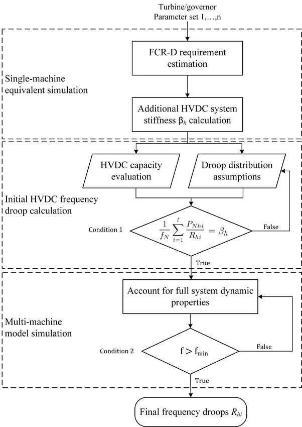
Fig. 6. A flowchart to determine HVDC EPC frequency droop in pu for
Fig. 5. Droop control for HVDC EPC (sign are adjusted for HVDC power
individual HVDC links using single- and multi-machine models
import to NPS case)
Out of the 24 HVDC links present in the model, 18 connect
the NPS with asynchronous areas and one with the NSWPH.
EPC is a supplementary frequency control aimed at comple-
They are assumed to be all equipped with EPC. The activation
menting FCR-D, but its use can be extended to partly replacing
time delays are assumed negligible, since local measurements
conventional FCR-D procured within the synchronous zone.
are used. The activation threshold fT F L has been set to
The share of frequency control between FCR-D and EPC is
49.6 Hz, while the more conservative value of 49.9 Hz was
further discussed in the Appendix. When replacing FCR-D
used in [20]. The active power correction in each HVDC link
with EPC, the HVDCs system stiffness (βh ) can be calculated
is limited according to its operating point in order not exceed
from (4) in Appendix which yields the minimum system
the power capability of the converters. The droop between
stiffness provided by HVDCs to ensure a final steady-state
fT F L −f and PEP C has been determined using the equivalent
frequency above 49.5 Hz. The latter is used as an input to
droop method detailed in [20]. The corresponding flow chart
calculate the HVDC droops (Rhi (i = 1, ..., n)) and the final
is given in Fig. 6. First, for a realistic set of turbine/speed
frequency droop values, according to Fig. 6. However, the
governor parameters satisfying FCR-D requirements and for
”Condition 2” used in multi-machine model simulations is
the dimensioning incident, the HVDCs system stiffness (βh )
changed to satisfy steady-state frequency deviation constraint
is identified for a given total kinetic energy level in NPS,
(∆fss > ∆Fss,max ).
using the single-machine equivalent model in [20]. Equal
droops in per unit are assumed for all HVDC links. Next, an Clearly, the frequency nadir after a generator outage de-
iterative procedure adjusts those individual frequency droops pends not only on the frequency droop values, but also on the
(Rhi ; i = 1, ..., n) taking into account the available HVDC settings of speed governors and HVDC outer control loops.
capacities, in order to keep the equivalent droop at NPS level The HVDC active power controller time response is tuned to
equal to βh . Finally, the individual droop values are adjusted be in the 100 − 200 ms range, which is considerably faster
based on simulations of the detailed, multi-machine system compared to hydro plant speed governor responses. Thus,
to account for the impact of other dynamic system properties replacing FCR-D with EPC will yield higher frequency nadir
such as power system stabilizers and the dependency of load values (or lower IFD) compared to a case when only generators
power to voltage. are used for FCR-D.6
Fig. 7. NPS frequency response to two disturbances. Left plot: individual Fig. 8. Cumulated variations of electrical powers from FCR-D units (left
speeds of FCR-D units. Right plot: average frequency of FCR-D units plot) and load active powers (right plot)
V. S IMULATION R ESULTS IFD criterion (at 49.0 Hz). Even more, the nadir value is
just at the limit of activating load shedding in the NPS (at
The simulation results presented in this section deal with the
48.8 Hz). Finally, the system stiffness is not sufficient to limit
frequency dynamics of the future Northern European AC/DC
the steady-state frequency deviation to the required value of
system, including the NPS and the NSWPH, without and with
0.5 Hz after the dimensioning incident. Expectedly, the results
EPC, respectively. The simulations involve large disturbances
are less severe for the Rossaga-G1 outage. The FCR-D units
such as generator or HVDC interconnector outages. They
are able to keep the frequency within the desired range with
illustrate various features of the model that may be of interest
a nadir at 49.17 Hz and a final frequency deviation of 0.4 Hz.
to other researchers.
The loss of voltage support by the tripped generator impacts
In all simulations, the system is initially in steady-state with
the nearby voltages and, hence, the load power, which in turns
the NPS frequency at 49.9 Hz (the lowest value with FCR-D
affects the frequency response. By way of illustration, Fig. 8
reserves not activated) and the NSWPH frequency at 50 Hz.
shows the cumulated variations of, respectively, electrical pow-
The contributions to system stiffness of generators (βg ) and
ers from FCR-D units and load active powers. The oscillations
HVDC links (βh ) are defined in the Appendix.
in load active power result from the coupling between voltage
magnitude and frequency: the voltage swings with the system
A. NPS frequency dynamics with FCR-D from generators frequency and the load power follows through its voltage
Two disturbances differing by the size and the location are dependency.
studied. The first one is the dimensioning incident outage The outage of Oskarshamn-3 results in a voltage dip which
of the Oskarshamn-3 1450-MW nuclear power plant. This at its maximum reduces the load consumption by 500 MW,
is currently considered as the most critical incident in NPS. while following the Rossaga-G1 incident, the maximum load
This generator is located in zone SE3 (see Fig. 1) serving a decrease is around 250 MW. This significant difference is
relatively high load of 9 GW. The second incident is the loss explained by the fact that the former incident involves a higher
of the Rossaga-G1 1040-MW generator. It is located in zone generation loss and impacts a higher load in its neighbourhood.
NO4. This zone serves a comparatively low load of 2 GW. The final load contribution is negligible for the Rossaga-G1
These two representative disturbances allow illustrating the outage, as confirmed by the right plot in Fig. 8, because the
impact on frequency response of voltage-dependent loads as load voltages almost recover their pre-disturbance values. In
well as proximity of the disturbance to load centers. Although contrast, the permanent contribution of loads is higher after the
these effects are sometimes disregarded in the analysis of Oskarshamn-3 outage. Indeed, voltages do not recover their
frequency control, they may be significant for proper design pre-fault values and load contributes with 50 MW to the final
of frequency reserves in low-inertia systems. frequency deviation, while FCR-D contributes with 1400 MW.
Fig. 7 presents the frequency responses to the aforemen-
tioned disturbances. The left plot shows the rotor speeds of B. NPS frequency dynamics with EPC
individual machines involved in FCR-D, while the right plot If the current frequency control requirements are kept
shows the average frequency of these units over a longer unchanged in the time horizon of this study, the FCR-D
time interval. The left figure shows, as expected, that both units will be unable to contain the IFD within ± 1 Hz after
disturbances excite local modes of oscillation that can be dimensioning incident trip and could even breach the load
observed on individual generators. Those oscillations are ade- shedding activation limit, as shown by Fig. 7. The results of
quately damped by the PSS, so that after some 13 seconds, all this section show that HVDC EPC can efficiently contribute
generators follow the global (common) mode of oscillation. to correcting this situation and are compared to Base Case
In response to the Oskarshamn-3 outage, the frequency nadir corresponding to the scenario described in Section V-A, where
reaches a low value of 48.78 Hz, which violates the maximum Oskarsham-3 tripped.7
1) Case 1: First, the case where HVDC EPC com- final frequency deviation of 0.5 Hz after the dimensioning
plements the FCR-D of generators is considered. Origi- incident. The new frequency droop is 0.0465 pu. This leads to
nally, ten generators provide FCR-D with a system stiffness increase the HVDC EPC contribution to system stiffness βh
βg = 3648 MW/Hz. It was found that setting the frequency by 3196 MW/Hz (changing from 519 to 3715 MW/Hz). Thus,
droops of HVDC EPC to a value as low as 0.33 pu is enough to the increase of βh is 2.6 times larger than the decrease of βg
meet the requirements in terms of nadir and final deviation of that had to be compensated. This comes from the different
frequency. The corresponding contribution to system stiffness frequency threshold used in DC/AC converters (49.6 Hz) with
is βh = 519 MW/Hz. The resulting frequency evolution is respect to that used in speed governors (49.9 Hz).
shown in Fig. 9. From Eq. (4) it is easily seen that, when the With the above settings, the frequency nadir is raised to
frequency settles below the triggering threshold fT F L , HVDC 49.36 Hz, as shown in Fig. 9. Thus, the NPS system operates
links contribute to active power generation, which decreases with a comfortable security margin. As desired, the frequency
the final frequency deviation. In this specific case, Fig. 10 settles at the final value of 49.5 Hz.
shows a cumulated contribution from HVDC links of 83 MW It should be noted that HVDC links become dominant in
while frequency settles above 49.5 Hz (see Fig. 9). the IFD containment, owing to the faster response of DC/AC
converters (for similar values of the frequency droops). For
instance, Fig. 10 shows that, at the time of frequency nadir
(t = 8.91 s), HVDC links inject a total 1,411 MW and
generators in FCR-D only 697 MW. The frequency oscillation
is also much better damped compared to the previous cases.
The reverse of the medal is that the 1,411 MW increase in
HVDC power flows account for 20% of the available capacity
at the considered operating point. In contrast, the frequency
droop of 0.33 pu (see Case 1) imroves the IFD while using
only 497.6 MW, accounting for only 7% of the available
capacity. The same tendency is noted in steady-state operation,
with respectively 622 MW and 83 MW delivered to NPS. Al-
though technically possible, FCR-D replacement with HVDC
Fig. 9. NPS frequency response without and with HVDC EPC (complement- EPC requires substantial amounts of free capacity on the
ing or replacing part of FCR-D) HVDC links. Presently several HVDC links connected to the
NPS have more than 100 MW free capacity 70% of the time
on a yearly average, but the available capacity might decrease
with larger power exchanges between countries, which would
reduce the effectiveness of EPC [36] [37]. Measures such as
capacity reservation, could resolve the issue at an additional
price, but this must be coordinated with frequency reserve
procurement in other areas. Currently, capacity reservation and
frequency reserve procurement outside NPS is on a bilateral
contract basis and coordinating and delivering the power
reliably to NPS could be an issue.
C. NPS frequency dynamics with support from NSWPH
This section deals with NPS frequency support from the
NSWPH, as well as frequency control in the NSWPH itself.
Fig. 10. Cumulated active power response of HVDC links (solid line) and The control of the NSWPH frequency has been outlined
FCR-D units (dashed lines) in the NPS in Section III. It relies on the active power control loops of
the offshore AC/DC terminal converters. In the low-inertia
Furthermore, Figs. 9 and 10 clearly show that the fast option the latter operate in grid-following mode with frequency
correction applied by HVDC EPC significantly improves the droops set to 3.5 pu, a value that allows the SCs to play
damping of the common mode oscillation, compared to the their role of kinetic energy buffers while preventing too large
situation with FCR-D from generators only. deviations of their rotor speeds (and, hence, of frequency). In
2) Case 2: Next, the case where HVDC EPC partly re- the zero-inertia option, the same converters operate in grid-
places the FCR-D of generating units is considered. Thus forming mode with frequency droops set to 0.01 pu to ensure
FCR-D is procured by generators in areas asynchronous with small-signal stability of the offshore system [32]. In both
NPS. To this purpose, three hydro generators in the NPS cases, the integral gain Khc of the hub controller was set to
were removed from the FCR-D, which reduces their con- 1.65 pu/s. The onshore AC/DC terminal converters control the
tribution to system stiffness βg by 1230 MW/Hz (changing DC voltages of their respective links.
from 3648 to 2418 MW/Hz). The missing system stiffness is HVDC EPC has been assigned to the link between NSWPH
compensated by HVDC EPC, re-tuned to achieve the same and Norway (see Fig. 2), referred to as NSWPH-NO. The8
A corresponding change of slope is observed in the evolution
of the NSWPH frequency.
For an EPC droop value of 0.33 pu the NSWPH frequency
deviates by less than 0.1 Hz. Clearly, larger deviations would
be observed for larger values of the droop.
If EPC alone was considered, the power in the NSWPH-NO
link would decrease to 367 MW at the time of NPS frequency
nadir and would eventually settle to 427 MW. However, this is
not the case since the offshore terminal converter of that link
also participates in the control of the NSWPH frequency, as
explained in Section III. Since initially the NSWPH frequency
decreases, the power flow from NO to NSWPH is increased,
which slightly counteracts the decrease imposed by EPC. The
simulation results show indeed a power flow of 379 MW at
the time of NPS frequency nadir and 430 MW in the final
steady state.
2) Outage of the NSWPH-NL HVDC link: This disturbance
affects the active power balance of the NSWPH to a much
greater extent. Figure 12 compares the low- and zero-inertia
options in terms of NSWPH and NPS frequencies, power flow
in the NSWPH-NO link, and sum of power flows in the other
links connected to the NSWPH.
In the low-inertia design, the kinetic energy storage in the
Fig. 11. Dimensioning incident in NPS with HVDC EPC on NSWPH-NO SCs yields a smoother active power adjustment of the offshore
link and low-inertia option for NSWPH: evolution of frequencies and active
power flows AC/DC converters. The rotor speeds and, hence, the NSWPH
frequency, deviate quite significantly, with a maximum of
2.61 Hz. Although this deviation should be carefully taken
active power control loop of its offshore terminal is pro- into account when setting protections, no load is impacted in
vided with a supplementary control receiving the onshore the offshore grid. Furthermore, the deviation could be made
frequency error signal. The corresponding frequency droop smaller by increasing the inertia of the rotating masses (using
was set to 0.33 pu. The same NPS dimensioning incident as flywheels). The shown results correspond to a low value of 2 s
in Sections V-A and V-B is considered. The simulation results for the inertia constant H of the SCs. The frequency deviation
correspond to the low-inertia option. is slowly corrected by the hub controller with integral action,
NSWPH is a system extension and, as such, it can be the bringing the NSWPH frequency back to 50 Hz in some 80 s.
source of additional disturbances. In this context, simulation In contrast, in the absence of offshore energy storage, the
results are provided pertaining to the outage of the HVDC zero-inertia design results in an almost instantaneous response
link connecting NSWPH and The Netherlands (see Fig. 2), of the AC/DC converters operating in grid-forming mode. The
referred to as NSWPH-NL. With a pre-disturbance power flow NSWPH frequency reaches its post-disturbance value in a few
of 1743 MW, the loss of that link significantly impacts the milliseconds and deviates from the nominal value by 0.12 Hz
active power balance of the isolated, offshore AC system. For only. This is to be expected from the respective frequency
comparison purposes, results are provided for the zero- and droop values: 3.5 pu for the grid-following converters vs.
low-inertia designs of NSWPH. 100 pu for the grid-forming ones. The small deviation will
1) Dimensioning incident in NPS: Fig. 11 shows the also be corrected by the integral hub controller.
NSWPH and NPS frequencies, the power flow in the The almost instantaneous response of the zero-inertia de-
NSWPH-NO link, and the sum of power flows in the other sign is also easily seen from the HVDC link powers. They
links connected to the NSWPH, in response to the dimen- reach their post-disturbance values in some 0.2 s with a tiny
sioning incident. At 6.02 s the NPS frequency drops below overshoot. The rate of change is less abrupt in the low-inertia
49.6 Hz, thus activating EPC on the NSWPH-NO link. The case, resulting in a slower propagation of the disturbance in
power flow from NO to NSWPH is decreased to support the the HVDC links and to the onshore grids.
NPS frequency. The steady-state difference observed for the power flow in
The frequencies of the NSWPH and NPS systems are the the NSWPH-NO link is due to the AC/DC converter of the
coupled through the EPC on the NSWPH-NO link, and the NSWPH-GB link reaching its maximum current in the low-
oscillations of the NSWPH frequency follow those of the NPS, inertia scenario. This increases the participation in NSWPH
through the power changes imposed by the terminal converter frequency control of the other, non-limited AC/DC converters.
of that link. Furthermore, when the NPS frequency transiently By taking that limit into account in a more refined version of
exceed the fF T L threshold, shown with dashed line in the the hub controller, this discrepancy could be eliminated.
lower left plot in Fig. 11, the EPC contribution vanishes and That change of power flow in the NSWPH-NO link disturbs
the power flow in the NSWPH-NO link regains its initial value. the power balance of the NPS, in which it is felt as a load9
Fig. 12. Outage of the NSWPH-NL link: NSWPH and NPS frequencies, power flows in NSWPH-NO and sum of power flows in the other links, with the
low- and zero-inertia designs
decrease. This causes a raise of the NPS frequency. The A PPENDIX
maximum IFD, reached at 7.3 s, amounts to 0.35 Hz in the S HARE OF FREQUENCY CONTROL BETWEEN FCR-D AND
low-inertia option, and 0.33 Hz in the zero-inertia option. EPC
The former deviation is slightly larger since the power flow It is considered that a fraction of FCR-D is procured outside
in NSWPH-NO further decreases in the low-inertia scenario. the synchronous zone (namely by GB and CE in the case of
The rate of change of frequency does not show a substantial NPS). The frequency containment process is characterized by
difference, and the onshore frequency response does not sig- its fast dynamic response, intended to limit the IFD, and by
nificantly depend on the choice between zero- and low-inertia its participation in the final steady-state frequency deviation.
scenarios, for this specific disturbance. The latter aspect is of concern hereafter.
After a power disturbance ∆Pdis , the system active power
VI. C ONCLUSION balance in steady state can be expressed as:
g
In this paper, the Northern European AC/DC power system X
o
Pgi − (f − fF CR−D )βg +
model is presented for a future low inertia NPS. Simulation
i=1
results are reported for large disturbance with and without l
EPC, respectively. Moreover, a plausible NSWPH solution
X
o
+ Phi − (f − fT F L )βh = PL + ∆Pdis (1)
based on an AC collection hub is presented for low- and i=1
zero-inertia topologies enabling large wind power integration
where system stiffness provided from generators and HVDCs
and additional frequency support to NPS.
respectively are expressed as follows:
It is shown that if the current frequency control requirements
are kept unchanged and the dimensioning incident occurs, then g l
1 X PN gi 1 X PN hi
it may not be possible to contain the frequency within the βg = βh = (2)
fN i=1 Rgi fN i=1 Rhi
acceptable frequency range. This could trigger more severe
frequency control mechanisms, such as load shedding, to coun- and g is the number of generators, l the number of HVDC
teract system degradation. It also shows that FCR-D alone may o o
links contributing to EPC, Pgi (resp. Phi ) the power setpoint
be unsuitable to manage the risk and that additional reserves of the i-th generator (resp. HVDC link), PN gi (resp. PN hi ) the
may need to be procured from elsewhere. For example, IFD nominal active power of the i-th generator (resp. HVDC link),
requirements could be satisfied by activating EPC on HVDC f (resp. fN ) the post-disturbance steady-state (resp. nominal)
links. The simulation results show that HVDC EPC can be frequency, fF CR−D (resp. fT F L ) the frequency threshold for
used to complement the existing FCR-D and can also be used activation of FCR-D (resp. EPC), Rgi the steady-state speed
to partly replace FCR-D, which was provided by conventional droop of the i-th generator, Rhi the frequency droop of the
generating units. It was shown that frequency droop based i-th HVDC link involved in EPC, PL the total active power
HVDC EPC can considerably improve the IFD, due to the consumption (including network losses).
faster active power control of HVDCs compared to hydro Note that (1) holds true only when the system frequency
generation. settles below fT F L , enabling a permanent contribution from
When investigating the interaction between the NSWPH EPC in the post-fault configuration. Assuming that the system
and the NPS, it was shown that the model can be used to initially operates at the nominal frequency (f = fN ) the pre-
study to which extend the hub can support the NPS and disturbance power balance can be written as:
how disturbances on the hub propagate to the NPS. For g l
that purpose, the model includes a low- and a zero-inertia X
o
X
o
Pgi + Phi = PL (3)
configurations of the NSWPH. i=1 i=110
and (1) can be rearranged to obtain the steady-state frequency [18] A. Monti, F. Milano, E. Bompard, X. Guillaud, Converter-Based Dy-
deviation: namics and Control of Modern Power Systems, Academic Press, 2021,
Pages 235-272, ISBN 9780128184912, https://doi.org/10.1016/B978-0-
" 12-818491-2.09992-2.
[19] A. Tosatto, M. Dijokas, T. Weckesser, S. Chatzivasileiadis, R. Eriksson,
1 “Sharing Reserves through HVDC: Potential Cost Savings in the Nordic
∆f = f − fN =− ∆Pdist +
βg + βh Countries”, in IET Generation, Transmission & Distribution, Sep. 2020.
# [20] D. Obradović, M. Ghandhari and R. Eriksson, ”Assessment and Design
of Frequency Containment Reserves with HVDC Interconnections,” 2018
+ (fN − fF CR−D )βg + (fN − fT F L )βh (4) North American Power Symposium (NAPS), Fargo, ND, 2018, pp. 1-6,
doi: 10.1109/NAPS.2018.8600593.
[21] D. Obradovic, M. Oluic, R. Eriksson and M. Ghandhari, ”Supplementary
(1) shows that, for the same frequency droop values, HVDC Power Control of an HVDC System and its Impact on Electromechanical
links contribute less than generators, due to different frequency Dynamics,” in IEEE Transactions on Power Systems, doi: 10.1109/TP-
error input, owing to the lower activation threshold of EPC WRS.2021.3056763.
[22] G. Misyris, T. Van Cutsem, J. . Moller, M. Dijokas, O. Renom Estragues,
than for FCR-D. From (4) it can consistently checked that by B. Bastin, S. Chatzivasileadis, A. H. Nielsen, T. Weckesser, J. Ostergaard,
replacing FCR-D with EPC without any adjustment of Rgi F. Kryezi, “North Sea Wind Power Hub: System Configurations, Grid
and Rhi , the denominator term decreases while the bracket Implementation and Techno-economic Assessment”, in Cigre e-Session
2020, Paris, France, pp.1-15, Aug. 2020.
term increases. Both contribute to making ∆f more negative. [23] P. Kundur, Power system Stability and Control, EPRI Power System
Therefore, when replacing FCR-D with EPC, the HVDC link Engineering Series, McGraw Hill, 1994.
frequency droops must be properly selected to obtain the same [24] ENTSO-E: ‘Nordic Balancing Philosophy,’ European Network of Trans-
mission System Operators for Electricity (ENTSO-E) Tech. Rep., Jun.
steady-state frequency deviation. 2016
[25] DIgSILENT, “PowerFactory 2018 - User Manual,” Oct. 2018.
R EFERENCES [26] M.Dijokas, D. Obradović, G.Misyris, T. Weckesser and T. Van Cutsem,
Northern European AC/DC Power System model, GitHub repository,
[1] O. Dudurych and M. Conlon, “Impact of Reduced System Inertia as a 2021. Available: https://github.com/thematt199310/NorthEuropeanAC-
Result of Higher Penetration Levels of Wind Generation,” in 2014 49th DCPowerSystem-Model/.
Int. UPEC, 2014, pp. 1–6. [27] ”IEEE Guide for Synchronous Generator Modeling Practices and Param-
[2] EirGrid and SONI, “RoCoF Alternative and Complementary Solutions eter Verification with Applications in Power System Stability Analyses,”
Project,” Tech. Rep., Mar. 2016. in IEEE Std 1110-2019 (Revision of IEEE Std 1110-2002), vol., no.,
[3] AEMO, “Future Power System Security Program (FPSSP) - Progress pp.1-92, 2 March 2020, doi: 10.1109/IEEESTD.2020.9020274.
report,” Tech. Rep., Mar. 2017. [28] E. Hillberg, ”Development of improved aggregated load models for
[4] National Grid, “Operating a Low Inertia System - A System Operability power system network planning in the Nordic power system Part 2:
Framework document,” Tech. Rep., Feb. 2020. Method verification,” Cigre 2018 Session, Ref. C4-310 2018, Paris, 2018.
[5] Nordic TSOs, “Challenges and Opportunities for the Nordic Power [29] N. Vovos and CIGRE Working Group 14.02, ”The CIGRE HVDC
System,” Tech. Rep., Aug. 2016. benchmark model - A new proposal with revised parameters,” ELECTRA
[6] IRENA, ”Renewable energy statistics 2020,” Tech. Rep., Jul. 2020, ISBN: 157, p. 61-66, 1994.
978-92-9260-246-8, p. 28. [30] The North Wind Power Hub Consortium, ”The vision: The Hub-and-
[7] WindEurope, ”Wind energy in Europe: Scenarios for 2030,” Tech. Rep., Spoke concept as modular infrastructure block to scale up fast”, June
Sep 2017. 2019.
[8] C. George et al. (2019). Electricity interconnections with neighbouring [31] M. Paolone, C.T. Gaunt, X. Guillaud, M. Liserre, A.P. Meliopoulos,
countries - Second report of the Commission Expert Group on electricity A. Monti, T. Van Cutsem, V. Vittal, C. Vournas, Costas, “Fundamentals
interconnection targets. 10.2833/092722. of Power Systems Modelling in the Presence of Converter-Interfaced
[9] European Commision, ”Political Declaration on energy cooperation be- Generation”, Proc. 21st Power System Computation Conference (PSCC),
tween the North Seas Countries,” Jun. 2016. 2020
[10] Svenska kraftnät: ‘Långsiktig marknadsanalys 2018 (Long-term market [32] G. Misyris, S. Chatzivasileiadis and T. Weckesser, ”Grid-forming con-
analysis 2018),’ Tech. Rep., Jan. 2019. verters: Sufficient conditions for RMS modeling,” Electric Power Systems
[11] E. Ørum et al., “Future System Inertia 2,” European Network of Research, Volume 197, 2021, ISSN 0378-7796.
Transmission System Operators for Electricity (ENTSO-E), Tech. Rep., [33] G. Misyris, A. Tosatto, S. Chatzivasileiadis and T. Weckesser, ”Zero-
Aug. 2018. inertia Offshore Grids: N-1 Security and Active Power Sharing,” Submit-
[12] E. Solvang, I. Sperstad, S. Jakobsen and K. Uhlen, ”Dynamic simulation ted to IEEE Transaction on Power Systems, 2020.
of simultaneous HVDC contingencies relevant for vulnerability assess- [34] T. Qoria, F. Gruson, F. Colas, G. Denis, T. Prevost and X. Guil-
ment of the nordic power system,” IEEE Milan PowerTech, June 2019, laud, ”Critical Clearing Time Determination and Enhancement of Grid-
Milan, Italy. Forming Converters Embedding Virtual Impedance as Current Limi-
[13] M. Kuivaniemi et al., ”New primary reserve requirements in the Nordic tation Algorithm,” in IEEE Journal of Emerging and Selected Topics
synchronous area – Designing the disturbance reserve,” Cigre 2018 in Power Electronics, vol. 8, no. 2, pp. 1050-1061, June 2020, doi:
Session, Ref. C2-203 2018, Paris, 2018. 10.1109/JESTPE.2019.2959085.
[14] B. Hartmann, I. Vokony, and I. Taczi, “Effects of decreasing synchronous [35] A. Tosatto, X. Martı́nez-Beseler, J. Østergaard, P. Pinson and S. Chatzi-
inertia on power system dynamics - Overview of recent experiences and vasileiadis, ”North Sea Energy Islands: Impact on National Markets and
marketisation of services,” Int. Trans. Electr. Energy Syst., vol. 29, no. Grids,” Submitted to Energy Policy, 2021.
12, June 2019. [36] Nord Pool Group: Historical market data. [Online]. Available:
[15] ENTSO-E: ‘Fast Frequency Reserve – Solution to the Nordic inertia https://www.nordpoolgroup.com/historical-market-data/ [Accessed: 2021-
challenge,’ European Network of Transmission System Operators for 05-14]
Electricity (ENTSO-E), Tech. Rep., Dec. 2019. [37] J. Huang and R. Preece: ‘HVDC-based fast frequency support for low
[16] O. Saborı́o-Romano, A. Bidadfar, J. N. Sakamuri, L. Zeni, Ö. Göksu inertia power systems,’ in 13th IET International Conference on AC and
and N. A. Cutululis, ”Communication-Less Frequency Support From DC Power Transmission (ACDC 2017), Feb. 2017, pp. 1–6.
Offshore Wind Farms Connected to HVdc via Diode Rectifiers,” in IEEE
Transactions on Sustainable Energy, vol. 12, no. 1, pp. 441-450, Jan.
2021, doi: 10.1109/TSTE.2020.3004630.
[17] M. N. Ambia, K. Meng, W. Xiao, A. Al-Durra and Z. Y. Dong,
”Adaptive Droop Control of Multi-Terminal HVDC Network for Fre-
quency Regulation and Power Sharing,” in IEEE Transactions on Power
Systems, vol. 36, no. 1, pp. 566-578, Jan. 2021, doi: 10.1109/TP-
WRS.2020.2999443.You can also read