Construction and commissioning of the - Horizon 2020 research and innovation programme Project: No 690323 SMART-Plant
←
→
Page content transcription
If your browser does not render page correctly, please read the page content below
This project has received funding from
                                                       the European Union’s Horizon 2020
                                                             Ref. Ares(2017)4843381 - 04/10/2017
                                                       research and innovation programme
                                                       under grant agreement No. 690323

  Horizon 2020 research and innovation programme

            Project: No 690323 SMART-Plant

                         Full project title:
Scale-up of low-carbon footprint material recovery techniques
   in existing wastewater treatment plants (SMART-Plant)

                         DeliverableD3.2

        Construction and commissioning of the
                 SidestreamSMARTechs

                Due date of deliverable: 31 May 2017

                 Actual submission date: 04 Oct 2017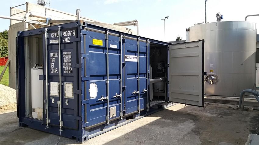
Project: No 690323

DOCUMENT INFORMATION:

                                                                     Construction and commissioning of the
Deliverable               Number              D3.2        Title:
                                                                     Sidestream SMARTechs

Work Package              Number              WP3         Title:     Side- and Down-stream SMARTechnologies

Due date of deliverable   Contractual                M6                   Actual               M6

Version number            1.0

Format                    Pdf file

Creation date             15/05/2017

Version date              20/09/2017

Type                            R                  DEM             DEC                OTHER          ETHICS

Dissemination Level             PU Public                                    CO Confidential

Rights                    Copyright “SMART-Plant Consortium”.

                          During the drafting process, access is generally limited to the SMART-Plant
                          Partners.

Responsible author                          Paolo Pozzato, Davide                   pozzato@scaevicenza.it;
                          Name:             Savio,                 Monica E-mail: tecnico@scaevicenza.it,
                                            Miglioranza                             segreteria@scaevicenza.it

                          Partner:          SCAE                          Phone: +39 0444 360 533

Other authors                               Constantinos           Noutsopoulos,
                                            Simos Malamis, Daniel Mamais,
                          Name:                                                    Partner:    NTUA
                                            Andreas Andreadakis, Evangelos
                                            Statiris

                          Name:             Nicola Frison, David Bolzonella        Partner:    UNIVR

                          Name:             Daniele Renzi                          Partner:    ATS

SMART-Plant D3.2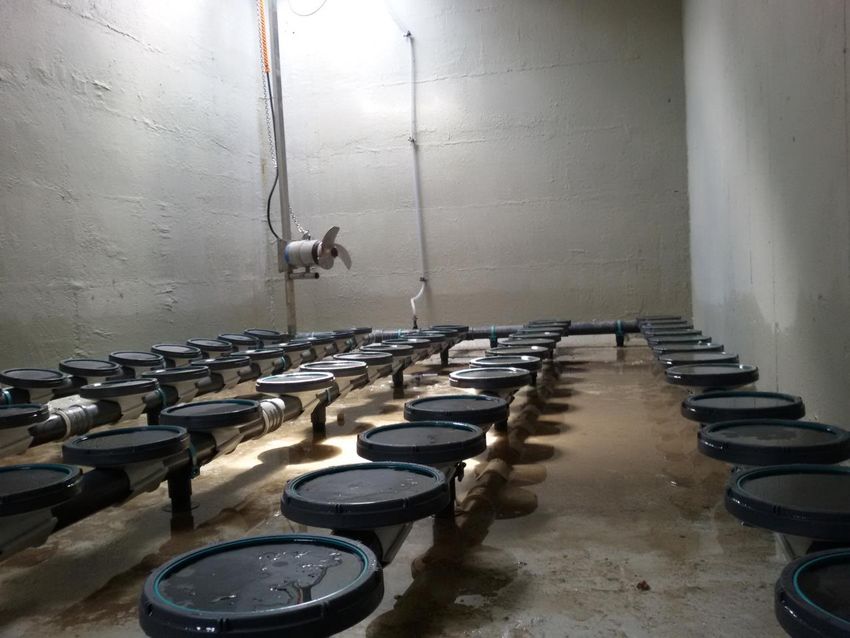
Project: No 690323

                                             Ioanna Droubogianni, Dimitra
                               Name:         Kollia, Panagiotis Lalis, George Partner:        AKTOR
                                             Zarras

Brief Description              Deliverable 3.2 is part of WP3 which is related to side- and down-stream
                               SMARTechnologies. More specifically D3.2 focuses in three sidestream
                               SMARTechnologies that are integrated in the existing conventional sewage
                               sludge treatment line to provide more energy efficiency for the i) removal of
                               nitrogen, ii) recovery of phosphorus and iii) recovery of PHA. The D3.2 is to the
                               construction and the commissioning of the sidestream SMARTechs.

Keywords                       sidestream Smartechs, construction, commissioning

Version log Revision history

Rev. No.       Issue Date               Modified by                     Comments

                                                                        Minor revision by Coordinator before
Version 1      03/10/2017               Francesco Fatone
                                                                        submission

SMART-Plant D3.2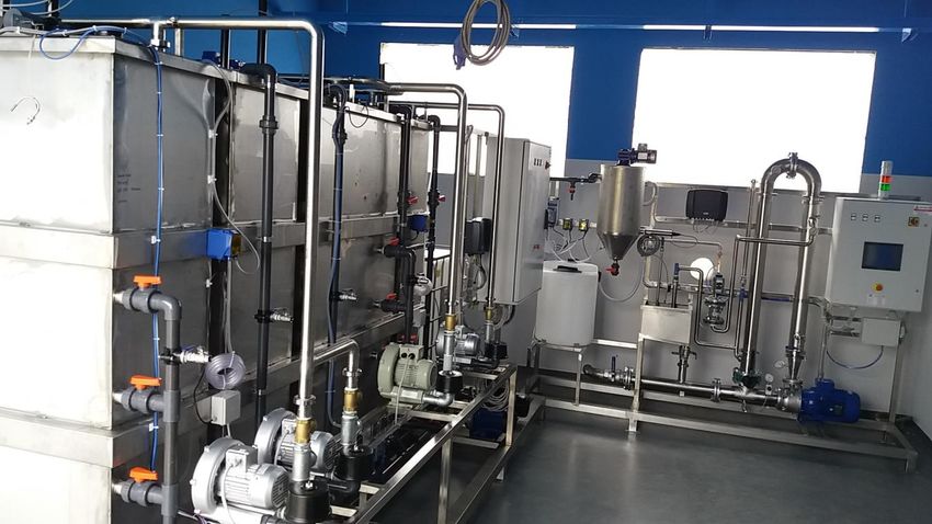
Project: No 690323

TABLE OF CONTENTS

Document Information: ......................................................................................................................... 2
Table of Contents ................................................................................................................................... 4
List of Tables .......................................................................................................................................... 5
List of Figures ......................................................................................................................................... 5
Executive Summary................................................................................................................................ 6
Abbreviations ......................................................................................................................................... 9
1.         Introduction ............................................................................................................................. 11
2.         SMARTech4a - Sidestream SCENA ........................................................................................... 13
2.1        Technical description of the SMARTech 4A ............................................................................. 13
2.2        List of the electromechanical equipment ................................................................................ 16
2.3        Practical instructions for the operation of SMARTech 4A ....................................................... 23
2.1        Integrability of the Smartech 4a in existing WWTPs ............................................................... 25
2.2        Drawings ‘as built’ .................................................................................................................... 27
2.3        Picture report ........................................................................................................................... 28
3.         SMARTech4b - Sidestream THERMAL HYDROLYSIS-SCENA ..................................................... 32
3.1        Technical description of the SMARTech 4B ............................................................................. 32
3.2        List of the electromechanical equipment ................................................................................ 35
3.3        Practical instructions for the operation of SMARTech 4B ....................................................... 39
3.1        Integrability of the Smartech 4b in existing WWTPs ............................................................... 42
3.2        Drawings ‘as built’ .................................................................................................................... 44
3.3        Pictures report ......................................................................................................................... 44
4.         SMARTech5 - Sidestream SCEPPHAR ....................................................................................... 52
4.1        Technical description of the SMARTech 5 ............................................................................... 52
4.1        List of the electromechanical equipment ................................................................................ 54
4.2        Practical instructions for the operation of SMARTech 5 ......................................................... 66
4.3        Integrability of the Smartech 5 in existing WWTPs ................................................................. 72
4.4        Drawings ‘as built’ .................................................................................................................... 74
4.5        Pictures report ......................................................................................................................... 74

 SMART-Plant D3.2
Project: No 690323

LIST OF TABLES

Table 1 Specification of the grinder for the mixed primary sludge. .................................................... 16
Table 2 Specification for the installation of the dynamic thickening .................................................. 16
Table 3 Specification of the fermentation unit.................................................................................... 18
Table 4 Specification for the installation of the screw-press separator for the mixed sludge
fermentation ........................................................................................................................................ 19
Table 5 Specification of the Short-Cut Sequencing Batch Reactor ...................................................... 19
Table 6 Operation of the fermentation unit ........................................................................................ 23
Table 7 Operation of the screw-press separator ................................................................................. 24
Table 8 Operation of the short-cut Sequencing Batch Reactor. .......................................................... 25
Table 9 Major units and specifications of the electro-mechanical equipment ................................... 36
Table 10 Basic features of automation in the operation of pilot plant system. .................................. 40
Table 11 List of electromechanical equipment and FLOW DIRECTION of the Salsnes Filter .............. 54
Table 12 List of tanks, electromechanical equipment, sensors and FLOW DIRECTION of the
Sequencing Batch Fermentation Reactor ............................................................................................ 55
Table 13 List of tanks, electromechanical equipment, sensors and flow direction of the ultrafiltration
unit ....................................................................................................................................................... 57
Table 14 Specification of the crystallization unit ................................................................................. 57
Table 15 List of tanks, electromechanical equipment, sensors and flow direction of the nitritation unit
.............................................................................................................................................................. 59
Table 16 List of tanks, electromechanical equipment, sensors and flow direction of the PHA-
accumulating biomass selection SBR ................................................................................................... 61
Table 17 List of tanks, electromechanical equipment, sensors and flow direction of the accumulation
SBR ....................................................................................................................................................... 64
Table 18 Operation of the SF1000 ....................................................................................................... 66
Table 19 Operation of the fermentation unit ...................................................................................... 67
Table 20 Operation unit of the ultrafiltration unit .............................................................................. 68
Table 21 Operation of the crystallizer ................................................................................................. 68
Table 22 Operation of the nitritation unit ........................................................................................... 70
Table 23 Operation of the selection SBR ............................................................................................. 71
Table 24 Operation of the accumulation SBR ...................................................................................... 72

LIST OF FIGURES

Figure 1 Deliverables of WP3 related to sidestream SMARTechs. ...................................................... 11
Figure 2 P&id of the Smartech 4a ........................................................................................................ 13
Figure 3 SMARTech 4a - Dynamic thickener of the sewage sludge ..................................................... 28
Figure 4 SMARTech 4a – Screw-press for S/L of the fermentation sewage sludge............................. 28
Figure 5 SMARTech 4a – Accumulation tank for the fermentation liquid of mixed sludge ................ 29
Figure 6 SMARTech 4a – Different views of the fermentation ............................................................ 29
Figure 7 SMARTech 4a - Electrical Panel and air compressor of Smartech 4a .................................... 30
 SMART-Plant D3.2
Project: No 690323

Figure 8 SMARTech 4a -Tank for the acculation of the anaerobic supernatant and influent pump of
the scSBR .............................................................................................................................................. 30
Figure 9 SMARTech 4a - Air diffusion system of the scSBR ................................................................. 31
Figure 10 Flow diagram of Psittalia WWTP with SMARTech 4b .......................................................... 32
Figure 11 Major units of SMARTech 4b and their interconnections ................................................... 33
Figure 12. Plan view of SMARTech 4B ................................................................................................. 44
Figure 13 Plan view of SMARTech 4B .................................................................................................. 45
Figure 13 3D drawing of SMATech 4B ................................................................................................. 45
Figure 15 SMARTech 4B – construction phase .................................................................................... 46
Figure 16 SMARTech 4B – construction phase .................................................................................... 46
Figure 17 SMARTech 4B – construction phase – installation of reject water storage tanks............... 47
Figure 18 SMARTech 4B – construction of raw and treated reject water networks ........................... 47
Figure 19 SMARTech 4B – overview of feed pump, decanting pump and decanting network ........... 48
Figure 20 SMARTech 4B – overview of feed pump and decanting pump ........................................... 48
Figure 21 SMARTech 4B – decanting system ....................................................................................... 49
Figure 22 SMARTech 4B – chemicals and substrate dosing pumps .................................................... 49
Figure 23 SMARTech 4B – chemicals and substrate storage tanks ..................................................... 50
Figure 24 SMARTech 4B – installation of on-line probes .................................................................... 50
Figure 25 SMATech 4B – hydraulic testing of the SBR ......................................................................... 51
Figure 26 SMATech 4B –testing of the aeration system of the SBR .................................................... 51
Figure 27 P&id of the Smartech 5. ....................................................................................................... 52
Figure 28 SMARTech 5 - Integrated container with rotating belt filter intalled ................................. 74
Figure 29 SMARTech 5 - Hopper for the cellulosic primary sludge .................................................... 75
Figure 30 SMARTech 5 - Installation of the Smartech 5 ...................................................................... 75
Figure 31 SMARTech 5 - (a) Sequencing Batch Fermentation Reactor during the installation; (b)
Sequencing Batch Fermentation Reactor placed in the platform ....................................................... 76
Figure 32 Ultrafiltration unit ................................................................................................................ 76
Figure 33 SMARTech 5 - Ultrafiltration system (right side) and crystallizer (right side) ..................... 77
Figure 34 SMARTech 5 - Left side,Nitritation, Selection and Accumulation SBRs; Right side,
ultrafiltration system and cristallizer. .................................................................................................. 77
Figure 35 SMARTech 5 - Air diffusion system for the nitritation, selection and accumulation SBR. .. 78
Figure 36 SMARTech 5 - Hydraulic testing ........................................................................................... 78
Figure 37 SMARTech 5 – Testing of the air diffusion system. ............................................................. 79
Figure 38 SMARTech 5 – Screenshot of the PLC control panel ........................................................... 79

EXECUTIVE SUMMARY

Deliverable 3.2 is part of WP3 which is related to side- and down-stream SMARTechnologies. More
specifically D3.2 focuses in three sidestream SMARTechnologies that are integrated in the existing
conventional sewage sludge treatment line to provide more energy efficiency for the i) removal of

 SMART-Plant D3.2
Project: No 690323

nitrogen, ii) recovery of phosphorus and iii) recovery of PHA. The D3.2 is to the construction and the
commissioning of the sidestream SMARTechs.

A brief description of the sidestream Smartechs involved in WP3 is reported below:

SMARTech 4a focuses in the integration of conventional biogas recovery from sewage sludge with
sidestream energy-efficient and compact nitrogen removal and phosphorus recovery. It applies the
Short-Cut Enhanced Nutrient Abatement system (SCENA) which integrates the following processes:
(o) dynamic thickening of the mixed sludge, (i) acidogenic fermentation of cellulosic sludge to
produce VFAs as carbon source, and (ii) via nitrite nitrogen and phosphorus removal (by P-
bioaccumulation) from sludge reject water using an SBR. In this configuration, nitrogen is removed
through the bioprocesses of nitritation/denitritation, and Enhanced Biological Phosphorus removal
(EBPR) is accomplished via nitrite through the alternation of anaerobic/aerobic/anoxic conditions.

SMARTech4b aims to the integration of the enhanced biogas recovery (by thermal hydrolysis) of
sewage sludge with sidestream energy-efficient and compact nitrogen removal and phosphorus
recovery. It applies and optimize the Short-Cut Enhanced Nutrient Abatement processfor the
treatment of reject water with a very high ammonium nitrogen content (>1.2 gN/L) due to the pre-
treatment of sewage sludge through thermal hydrolysis. In order to increase the biodegradable
COD/N and COD/P ratios reject water from primary sludge gravity thickeners will be used.
Alternatively, sodium acetate will be also employed to increase the readily biodegradable COD in
reject water in order to efficiently remove nitrogen through short-cut nitrification/denitrification and
to accumulate phosphorus in sludge through enhanced biological P removal via denitritation or
aerobically. SMARTech4b is designed to treat approximately 2-3 m3/d of reject water from sludge
dewatering facilities. Based on the design, alternative operational conditions can be employed
depending on the type of external substrate provided. An SBR with an effective volume of at least 9
m3 will be installed and be equipped with aeration system, mixing apparatus, probes and meters for
automatic control of the process. The SBR will be fed with sludge liquors form the dewatering unit
and from primary sludge thickening unit. The sludge liquors before being fed to the SBR will be
collected in two storage tanks. Three chemical dosing units will also be installed in order to provide

 SMART-Plant D3.2
Project: No 690323

i) for sodium acetate addition (as a complementary external substrate), and ii) for pH control of the
process.

SMARTech5 enables the integration of conventional biogas recovery from sewage sludge with the
energy-efficient nitrogen removal from sludge reject water and the recovery of PHA and struvite. It
applies the Short-Cut Enhanced Phosphorus and PHA Recovery concept (SCEPPHAR), which was
conceived as a modified version of SCENA for WWTPs larger than 150 kPE. It accounts of the following
sub-processes: (i) acidogenic fermentation of cellulosic primary sludge for the production of VFAs
and the release of nitrogen and phosphorus in soluble forms (ammonia and phosphate); (ii) solid and
liquid separation of the fermentation products and recovery of struvite form the sewage sludge
fermentation liquid by the addition of Mg(OH)2 to favour phosphorus precipitation; (iii) ammonium
conversion to nitrite accomplished in a SBR; (iv) selection of PHA storing biomass in a SBR by the
alternation of aerobic feast conditions and followed by anoxic famine conditions for denitritation
driven by internally stored PHA as carbon source; (v) PHA accumulation using a fed-batch reactor to
maximize the cellular PHA content of the biomass harvested from the selection stage.

SMART-Plant has received funding from the European Union’s Horizon 2020 research and
innovation programme under grant agreement No 690323.

 SMART-Plant D3.2
Project: No 690323

ABBREVIATIONS

AOB            Ammonia Oxidizing Bacteria

BNR            Biological nutrient removal

BOD5           Biochemical oxygen demand

CHP            Combined heat and power

COD            Chemical oxygen demand

DO             Dissolved oxygen

DS             Dissolved solids

EBPR           Enhanced Biological Phosphorus removal

GHG            Green house gases

MLSS           Mixed liquor suspended solids

MLVSS                 Mixed liquor volatile suspended solids

NH4-N          Ammonium nitrogen

NLR            Nitrogen loading rate

NOB            Nitrite Oxidizing Bacteria

ORP            Oxidation-reduction potential

OTR            Oxygen transfer rate

PHA            Polyhydroxyalkanoates

PLC            Programmable logic controller

SBR            Sequencing Batch Reactor

SCENA          Short-Cut Enhanced Nutrient Abatement process

SCEPPHAR       Short-Cut Enhanced Phosphorus and PHA Recovery concept

SL-DS          Sludge liquor-Dewatered sludge

SMART-Plant D3.2
Project: No 690323

SL-PS           Sludge liquor-Primary sludge

SOTE            Diffuser efficiency

SOTR            Standard oxygen transfer rate SRT

SVI             Sludge volume index

TN              Total nitrogen

TP              Total phosphorus

ΤS              Total solids

TSS             Total suspended solids

VFAs            Volatile fatty acids

VSS             Volatile suspended solids

WAS             Waste Activated Sludge

WWTP            Wastewater Treatment Plant

 SMART-Plant D3.2
Project: No 690323

1. INTRODUCTION

Deliverable 3.2 is part of WP3. WP3 main objective is to test and validate both side- and downstream
SMARTechnologies. More specifically WP3 includes 1) three Sidestream SMARTechs that will
integrate the existing conventional and enhanced biogas recovery from sewage sludge aiming at the
energy-efficient removal of nitrogen, recovery of phosphorus and PHA and 2) two Downstream
SMARTechs that will process the resource rich sludge to recycle raw material for following reuse in
agricultural and construction sectors.

WP3 consists of five tasks:

    Task 3.1 enabling sidestream SMARTech 4a with a duration of 42 months
    Task 3.2 enabling sidestream SMARTech 4b with a duration of 42 months
    Task 3.3 enabling sidestream SMARTech 5 with a duration of 42 months
    Task 3.4 enabling downstream SMARTech A with a duration of 30 months
    Task 3.5 enabling downstream SMARTech B with a duration of 30 months

In the context of WP3 six deliverables are foreseen. Deliverables 3.1-3.3 & 3.5 are related to the three
sidestream SMARTechs. The short title of each of the deliverables and their month of delivery is
illustrated in Figure 1.

Figure 1 Deliverables of WP3 related to sidestream SMARTechs.

The present report is the second of these series of deliverables. D3.2 presents the costruction,
installation and commissioning of the sidestream Smartetech.

 SMART-Plant D3.2
Project: No 690323 D3.2 is structured in four chapters and annexes, including this introduction, which presents the objectives of this report and its structure. For each technology, the report is structurized a technical of the SMARTech is 1- Technical description of the SMARTech 4a, 4b and 5; 2- List of the electromechanical equipment 4a, 4b and 5; 3- Practical instructions for the operation of SMARTech 4a, 4b and 5; 4- Drawings ‘as built’ 5- Picture reports Finally, Annex presents the executive drawing “as built” of the three Smartechs. SMART-Plant D3.2
Project: No 690323

2. SMARTECH4A - SIDESTREAM SCENA

 2.1 Technical description of the SMARTech 4A
The Smartech 4a is an innovantive technology aiming the via-nitrite nitrogen phosphorus removal
from the anaerobic supernatant. The overall system can be described according to the following
integrated operational units:
1)       (alkaline) fermentation of thickened sewage sludge at mesophilic conditions (37°C) for the
on-site production of best available carbon source (BACS), which is the optimal mix of volatile fatty
acids;
2)       A solid/liquid separation of the fermented sewage sludge by a screw press;
3)       A Sequencing Batch Reactor (SBR) for the short cut biological nitrogen removal and
phosphorus recovery via-nitrite through the dosage of the sewage sludge fermentation liquid.

Figure 2 P&id of the Smartech 4a

The optimization of the Smatech 4a was carried out during the design phase by the implementation
of the dynamic thickening of the mixed sewage sludge, which allows the increase of the organic
loading rate and the reduction of the sludge volume fed to the anaerobic digestor and the
fermentation unit. The dynamic thickener (SCAE) allows the thickening of up to 100 m3 of sewage

 SMART-Plant D3.2
Project: No 690323

sludge per day, according with a flowrate of 20 m3/h. The final concentration of the sewage sludge
will be around 5% (Total Solid based) thanks to the addition of a polyelectrolyte solution (0.8% of
active compound) by a dedicated machine. Around 10 m3 of thickened sludge fed the fermentation
unit, which has a total volume of 50 m3. The fermentation process works at around 30°C thanks to
the heater fed to the biogas produced from the full scale anaerobic digestor. A constant hydraulic
retention time of 5 days is controlled by two pneumatic and opposite valves, which are able to divert
the flowrate of the thickened sewage sludge to the fermentation unit or to the digestor according
with set-point level achieve in the fermentation unit. The solid/liquid separation of the fermented
sewage sludge is carried out by a screw-press (SCAE) able to produce around 2-4 m3/h of
fermentation liquid rich of volatile fatty acids. The liquid fractio is stored in a storage tank of 20 m3
to make it available for the further utilization during the anaerobic and anoxic phase of the scSBR.
The solid fermented fraction (13-15% total solids based) is not disposed due to the still high biogas
production potential, but it is mixed with the thickened mixed sludge which fed the anaerobic
digestor.
The scSBR has a maximal working volume of 70 m3, which allow the treatment of the daily flowrate
of anaerobic supernant produced after the dewatering operation of the anaerobic digestate under
3-4 cycles. The scSBR is equipped with a mixing system having a nominal power of 1.5 kW. The
aeration system consist of a volumetric blower (nominal power 11 kw) and n°80 diffusers (INVENT)
able to provide around 500 m3/h of compressed air at 400 mbar of pressure, in order to provide an
oxygen transfer efficiency up to 15%. The dissolved oxygen concentration in the bulk will be
controlled during the aerobic phase at 1.5 mg/L by a Variable Frequency Device (VFD) to module the
air flowrate of the blower.

There are two centrifugal pumps from FLYGHT manufacturer with capacity of 70 and 65 m3/h
respectively for the feeding and discharge of the scSBR. In each cycle, the feeding pump feeds
automatically around 10-15 m3 of anaerobic supernatant, which is taken directly from the storage
tank of 90 m3. The latter has a capacity to store enough anaerobic supernant for 2-2.5 days, which
takes into account the days when the WWTP of Carbonera is not supervised from the operators
(week-end) or when the dewatering operation are not taking placed. At the end of the cycle, the

 SMART-Plant D3.2
Project: No 690323

centrifugal sumberged pump installed at 0.8 m from the bottom of the scSBR allows the discharge of
the treated anaerobic supernatant in the headworks of the main WWTP.

The SBR is equipped with sensors from HACH-LANGE company which are based on a floating
chamber. The sensors allows the monitoring of several parameters and by them also the control of
the nitrogen forms, so to control the cycle lenght. The sensors installed are: pH, Dissolved Oxygen
(DO), Conductivity (COND), Oxydation Reduction Potential (ORP), Mixed Liquor Suspended Solids
(MLSS).

All the signal from the sensor are first collected by the controller SC1000 (HACH-LANGE) and then
transfer to a Programmable Logic Controller (PLC, SIEMENS) via a modbus protocol. The data can be
also recorded and used from the remote system of ATS. The control algortims installed in the PLC
provides the control of the electrical equipments, including the lenght of each phases, the automatic
dosage of the carbon source and the variable frequency driver to control the right dissolved oxygen
during aerobic phase.

 SMART-Plant D3.2
Project: No 690323

 2.2 List of the electromechanical equipment
Table 1 Specification of the grinder for the mixed primary sludge.

                                                GRINDER
 CODE           DESCRIPTION                         Unit               Value
 TR1            Grinder                             m3/h               20
                                                    rpm                270
                                                     Hz                50
 Description
 The grinder is used as for the size reduction of the coarse material present in the mixed sludge. The
 grinder has 4 self-sharpening cutting blades with a grid having a maximal pore size of 24 mm and 445
 cm2 of surface. The maximal operating pressure is 2 bar.

Table 2 Specification for the installation of the dynamic thickening

                                         DYNAMIC THICKENING
 CODE     DESCRIPTION                             Unit                 Flowrate
 ID       Dynamic thickening                      m3/h                 20

      List of electromechanical equipment included
 CODE DESCRIPTION                    Flowrate      Intalled     CONTROL
                                                   power
 P4   Feeding ID                     20 m3/h       7.5
 P7   Emulsion dosage                0-600 L/h     -
 P8   Poly solution dosage           2 m3/h        1.1
 P16  Washing ID pump                    3
                                     5 m /h        5.5
 P05  Feeding DA, POI, FRM               3
                                     6 m /h        4
 FLOW Feeding from (F)/ Discharge to (D)                 PUMP CODE
          Configuration 1: PRI -> ID -> FRM;              F1:P04
          Configuration 2: PRI -> ID -> POI;              F2:P07, P08
          Configuration 3: PRO ->ID-> DA                  D1: P05
                                                          D2: gravity
                                         SENSORS INSTALLED
 Code                                   M012
 Description                            Measurement of the total solids of the mixed sludge
 Technical description
 Probe with combined light infrared absorption for measuring turbidity and suspended solids
 Independent of the color of the water sample (suitable for waste activated sludge, primary sludge,
 SMART-Plant D3.2
Project: No 690323 etc). Component and configuration Configuration: insertion probe with steel probe body; Lenght of cable: 10 meters Technical data: photometer with double IR detector Method of measurement: Turbidity measurement according to DIN EN 27027; Measure Solids, equivalent to DIN 38414 Measurement range: Turbidity: 0.001 - 4.000; Total Solids: 0.001 - 50.0 g / l Accuracy: 1.0% turbidity, ± 0.001 FNU Coeff. Var process: 1.0% according to DIN 38402 Response Time: 0.5 s
Project: No 690323

Table 3 Specification of the fermentation unit

                                           FERMENTATION UNIT
 CODE           DESCRIPTION                            Size           Value
 FRM            Fermentation unit                      Diamete        4m
                                                       Height         4m
                List of electromechanical equipment included
 CODE           DESCRIPTION                 Flowrate        Intalled     CONTROL
                                                            power
 P05            Feeding FRM                     3
                                            6 m /h          7.5          Based on status of V3 and V4
 P09            Discharge FRM                   3
                                            6 m /h          0.55
 MX5            Mixer FRM                   -               1.5          Manual switch on/off
 HH             Heater                      55      (daily 14.7      kW The biogas is taken from the
                                            needs       of thermic       full scale anerobic digestion of
                                            biogas)         power        sewage sludge
 FLOW           Feeding from (F)/ Discharge to (D)                PUMP CODE
                FRM -> PC                                  F1:P05
                                                           D1:P09
                                          SENSORS INSTALLED
 Code                                    M010
 Description                             Measurement oft he pH and temperature of the fermentation
                                         unit (FRM)
 Technical description
 Differential type digital sensor for the measurement of pH and temperature. Electrode not in
 contact with the liquid bulk.
 Component and configuration
 Material of the electrode: glass;
 Type of probe: submerged
 Sensor body: steel
 Range of measurement: 0 - 14; T=-5° C a 50° C
 Time of response: pH: < 5 s; T: < 2 min
 Reference electrode for the control of the impedence of the liquid bulk
 Lenght of the cable: 10 metri
 Dimensions: 350 x 44 mm (diameter)
 Other equipments included
     -   Fixing system for pH, size 1" steel AISI316

 SMART-Plant D3.2
Project: No 690323
Table 4 Specification for the installation of the screw-press separator for the mixed sludge
fermentation
SCREW PRESS SEPARATOR
CODE DESCRIPTION Unit Flowrate
PC Screw Press for sludge m3/h 2-4
fermentation dewatering
List of electromechanical equip-ment included
CODE DESCRIPTION Flowrate Intalled CONTROL
power
P09 Feeding DA, POI, FRM 3
6 m /h 4 Controlled by frequency
inverted and leve ultrasonic
P13 Poly solution dosage 0.32 Controlled by frequency
inverted and leve ultrasonic
P11 Solid 3
fraction 0.6-3.2 m /h 5.5 Controlled by frequency
fermentation sludge inverted and leve ultrasonic
P10 Liquid fraction 2-5 m3/h 1.4 Controlled by min/max level
fermentation liquid sensor M022
FLOW Feeding from (F)/ Discharge to (D) PUMP CODE
FRM-> PC -> SCENA (Liquid fractio) F1: P09;
FRM ->PC -> POI (Solid fraction) F2: P13
D1: P11;
D2: P10
POLYELECTROLITE MACHINE
CODE DESCRIPTION Flowrate VALUE
PP2 Machine for preparation of m3/h
polyelectrolyte solution
List of electromechanical equipment included
CODE DESCRIPTION Flowrate Intalled CONTROL
power
P7 Emulsion dosage 0-600 L/h 0.5
P8 Poly solution dosage 1.1
FLOW Feeding from (F)/ Discharge to (D) PUMP CODE
PP2 -> FRM F1: P7;
PP2 -> ID D1: P8
D2:
Table 5 Specification of the Short-Cut Sequencing Batch Reactor
SMART-Plant D3.2Project: No 690323
SHORT-CUT SEQUENCING BATCH REACTOR
CODE DESCRIPTION Size Value
scSBR Short-Cut Sequencing Batch Max working 70 m3
Reactor Volume
Surface 8 x 2.9 m
Height 3.2 m
List of electromechanical equipment included
CODE DESCRIPTION Flowrate Intalled CONTROL
power
P1 Feeding scSBR 3
49 m /h 1.8 Switch on during the filling
phase (control by the PLC)
MX3 Mixer scSBR - 1.5 Switch on during the filling,
anaerobic and anoxic phase.
(control by the PLC)
BL1 Blower scSBR 3
170 ÷ 520 m /h 11 Switch on aerobic phase.
(control by the PLC)
P2 Discharge scSBR 70 m3/h 1.35 Switch on during the discharge
phase (control by the PLC)
P12 Carbon source 3
5 m /h 0.98 Switch on during the anaerobic
and anoxic phase (control by
the PLC)
P03 Purge 3
5 m /h 2.2 Manual switch on/off
FLOW Feeding from (F)/ Discharge to (D) PUMP CODE
FRM -> PC F1:P05
D1:P09
INSTALLED SENSORS
Code DO002
Description Measurement of dissolved oxygen of the selection SBR unit (R006)
Technical description
The measurement method is based on the emission of luminescent radiation by a special substance
(luminophore) that is excited by light blue emitted by a LED and returning to the normal state emits
light red. A photodiode measures the time needed to return to the quiescent state, inversely
proportional to the concentration of oxygen present on the luminophore.
Component and configuration
- Measuring principle: luminescent optic
- Measurement range: 0 to 20.00 mg / L (ppm) O2, 0 to 200% saturation
- Accuracy: 0-5 mg / L O2 ± 0.1 mg / L, 5-20 mg / L O2 ± 0.2 mg / L; Temperature: ± 0.2 ° C
- Repeatability: ± 0.1mg / L
- Resolution: 0.01 mg / L (ppm) O2 / 0.1% saturation
SMART-Plant D3.2Project: No 690323 - Response time (at 20 ° C): T90
Project: No 690323

- PVC pole (Ø 40mm, length 2 meters) - 1 "NPT sensor adapter
- swivel spindle
- brown tube closure cap

SMART-Plant D3.2
Project: No 690323

 2.3 Practical instructions for the operation of SMARTech 4A
The dynamic thinkening is fed using the volumetric pump P04 with a flow rate of 20 m3/h. To prevent
clogging due to tatters or other inert materials, a grinder by vogelsang company is installed before
the pump P04. However, in case of mantenance or techical problems, the P04 can be replaced by the
parent installed volumetric pump P06. The thickened mixed sludge (50 gTSS/L) is pumped using a
volumetric pump at 6 m3/h. The influent flowrate and the total solid concentration of the influent
mixed sluge are monitored by the inline sensors M012 (TSS) and M014 (Qf) respectively. A solution
of polyelectrolite is provided using the volumetric pump P09, where the flowrate is automatically
adjusted according with the registered total solids concentration of the influent and thickened mixed
sludge using the inline sensors M013 (TSS) and M015 (Qdig) respectively. Every day, 10 m3/d of
fermented sludge are discharge from the fermentation unit using the P09 and then fed with fresh 10
m3/d of thickened mixed sludge using the P05. The feeding and discharge of the fermentation unit
are controlled by the level sensor M009 and based on two opposite pneumatic valves (V3 and V4).
At minimun fixed level, the pneumatic valve V4 is kept closed, while the pneumatic valve V3 is open,
so to allow the feeding of thickened. The duration of the feeding is 1.7 hours. Once the maximal level
of the fermentation unit is achieved, the valve V3 close and V4 open.

Table 6 Operation of the fermentation unit

 Operation phase               Parameter that defines the phase Equipment in working
                               duration according to PLC design mode during this phase
                                                                controlled by PLC
 Filling (1 per day)           Level max                        The valve V3 open while
                                                                the valve V4 is closed
 Decanting (1 per day)         Level min                        The valve V4 open while
                                                                the valve V3 is closed

The screw press is fed using a volumetric pump with a maximal flowrate of 2-4 m3/h. The solid and
liquid separation of the mixed sludge fermentation results on two main stream: solid and liquid. The
liquid is pumped by a centrifugal pump using the storage tank of the carbon source. The solids
fraction is pumped by to the post dynamic thickening using the volumetric pump P11. The P9 is
controlled by the level of the fermentation. Every day, the screw press accomplishes the solid/liquid

 SMART-Plant D3.2
Project: No 690323
separation until when the minimun level of the fermentation unit is achieved. The fermentation liquid
produced is relaunched by the pump P10 from a temporary tank to the final storage tank of 20 m3
for its further application to the scSBR. The P10 is turned on when the level of the carbon source is
between the minimun and maximal level of the M022. The P10 stops the operation as soon as the
maximal level M011 is achieved. The eventual excess of carbon source production is drained by the
overflow and so discharged in the mainstream.
Table 7 Operation of the screw-press separator
Operation phase Parameter that defines the Equipment in working mode
phase duration according to PLC during this phase controlled by
design PLC
Filling Operation according to the level P9
MIN and MAX of the
fermentation unit
Relunch of the liquid Operation according to M022 P10
fraction
Discharge solid fraction Operation according to M011 P11
The scSBR is fed with around 40 m3/d of anaerobic supernatant using the suberged centrifugal pump
P01. The carbon source is provided by the volumetric pump P12. The effluent from the scSBR is
discharged using the submerged centrifugal pump P02. The waste activated sludge is withdrawn from
the scSBR using the P03. The anaerobic supernatant from the dewatering operation of the digestate
is sent by gravity in the equalization tank. The level M001 controlled the operation of two pneumatic
valve V13 and V14: at the minimal level achieved, the V13 is closed and V14 is opened, while at the
maximal level achieved the V13 is opened and V14 is closed. The daily flowrate of anaerobic
supernatant provided to the scSBR is divided in three or four cycle. The level M002 determines the
minimal and the maximal level achievable in the scSBR. Six sensors are installed in the reactor:
conductivity (M003), pH (M004), ORP (M005), DO (M006), MLSS (M007) and N2O (M008). Among
them, DO is used to control the compressor through VDF, while conductivity and pH are used to
control the lenght of the aerobic phase, the amount of carbon source and the lenght of the anoxic
phase. The other sensors are not included in the control algorithm of the system but are recorded in
the PLC.
SMART-Plant D3.2Project: No 690323
Table 8 Operation of the short-cut Sequencing Batch Reactor.
Operation phase Parameter that defines the phase Equipment in working
duration according to PLC design mode during this phase
controlled by PLC
Filling Timer or/and Level meter SBR mixing device
Sludge liquors feeding
pumps
Anaerobic phase Time based control SBR mixing device
(1 phase for each cycle) Monitoring of the process
parameters (pH, ORP,
Conductivity, Oxygen,
N2O, MLSS)
Aerobic phase Time based controlled for the Min Frequency of the blower
(1-2 phases during each and Max lenght of the phase; control by a PID algoritm
cycle) Real time control based on
conductivity and pH
Anoxic phase Time based controlled for the Min SBR mixing device;
(1-2 phases during each and Max lenght phases Carbon source feeding;
cycle) Dosage of the carbon source
according with the conductivity;
End of the phase according with
pH signals
Settling Timer -
Decanting Timer or/and Level meter Disharge pump
WAS removal Timer or/and Level meter Decanting pump
SBR mixing device
2.1 Integrability of the Smartech 4a in existing WWTPs
Integrability issues Smartech 4a
Technical Feasibiliy
1. Should new facilities always be No. Preliminary designs should be always performed in
considered during the design and order to consider the recovery of disused tanks or the
implementation of the Smartech? conversion of the existing facilities in the WWTPs. In
particular, the Smartech 4a was designed considering
SMART-Plant D3.2Project: No 690323
the conversion of existing tanks dedicated to the
storage of liquid waste.
2. Does the implementation of the No, if the Smartech 4a takes advantage of existing
Smartech imply a substantial change of works, only minor changes of piping connection are
the present flowscheme of the WWTP? required, which do not represent substantial changes
of the WWTPs.
3. Could the Smartech negatively impact No, the Smartech will positively impact on the final
on the final discharge of the main discharge, because the treated effluent from Smartech
WWTP? 4a is supposed to contain up to 90% less nitrogen and
30-60% less phosphorous compared with raw
anaerobic supernatant. However, even if the
technology does not perform as expected, the effluent
will be treated in the main WWTPs before its final
discharge in the water body.
Acceptability of the Smartech
1. Is the Smartech 4a well accepted The Smartech 4a is considered by operators an
among the operators? integrated and useful compartment of the WWTP and
the personnelle are used to operate and take care of
it.
2. Are specific skills and/or tranings No additional specific trainings are requireds. The
required for the operators? knowledge and expertize already held by the
operators of the main WWTP are also sufficient and
adequate to operate in the Smartech 4a. The latter in
fact uses the same equipments typically adopted also
by conventional biological processes.
SMART-Plant D3.2Project: No 690323
Bureaucratic issues
1. Did Smartech 4a require a specific Yes. The authorization for its implementation was
authorization for its implementation? asked to the Regional Authority (see the attachment).
Are there any standards, regulations or No, the Smartech 4a does not need to conform to
references applicable? specific regulation. However, if new facilities are
implemented, the competent autority may ask to
respect the standards of the “landscaping regulation”.
However, regulations could significantly change based
on the country where the plant is operating.
2.2 Drawings ‘as built’
The drawings of the units are reported in the following annexes:
• Drawing 1: P&id of the Smartech 4a
• Drawing 2: Fermentation unit
•
• Drawing 3: Layout of the Smartech 4a
• Drawing 4: Dynamic Thickening
• Drawing 5: Screw press separator
SMART-Plant D3.2Project: No 690323 2.3 Picture report Figure 3 SMARTech 4a - Dynamic thickener of the sewage sludge Figure 4 SMARTech 4a – Screw-press for S/L of the fermentation sewage sludge SMART-Plant D3.2
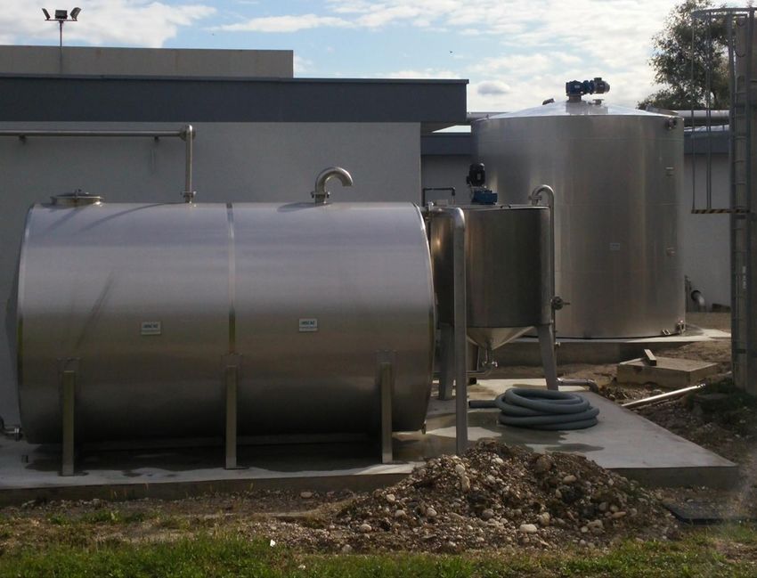
Project: No 690323

Figure 5 SMARTech 4a – Accumulation tank for the fermentation liquid of mixed sludge

Figure 6 SMARTech 4a – Different views of the fermentation

 SMART-Plant D3.2
Project: No 690323

Figure 7 SMARTech 4a - Electrical Panel and air compressor of Smartech 4a

Figure 8 SMARTech 4a -Tank for the acculation of the anaerobic supernatant and influent pump of
the scSBR

 SMART-Plant D3.2
Project: No 690323

Figure 9 SMARTech 4a - Air diffusion system of the scSBR

 SMART-Plant D3.2
Project: No 690323

3. SMARTECH4B - SIDESTREAM THERMAL HYDROLYSIS-SCENA

3.1 Technical description of the SMARTech 4B

The SMARTech 4b pilot system is an innovative nutrient removal process via nitrite which is
integrated in the Psyttalia WWTP in order to manage the reject water produced from the dewatering
process of the plant. The SMARTech 4b shall treat separately the reject water of the dewatering
process to biologically remove nitrogen and phosphorus and then recycle it back to the inlet of the
WWTP (Figure 3.1). This process also takes advantage of the readily biodegradable COD which is
contained in the reject water of the primary thickened sludge in order to provide part of the carbon
source which is required to remove nutrients from dewatered sludge.

Figure 10 Flow diagram of Psittalia WWTP with SMARTech 4b

Figure 10 illustrates the major units of the pilot system along with their interconnections. The core
of   SMARTech 4B is the bioreactor (SBR). The SBR is a rectangular tank with dimensions
[2.00x2.30x2.40] [WxLxH] and 9m3 maximum active volume. The construction material is stainless
steel AISI 304L.

 SMART-Plant D3.2
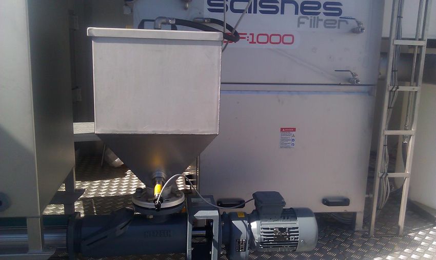
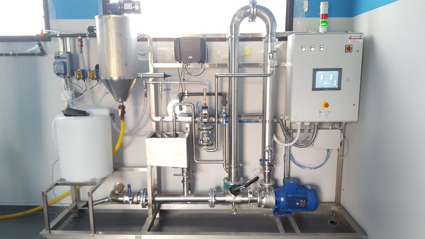
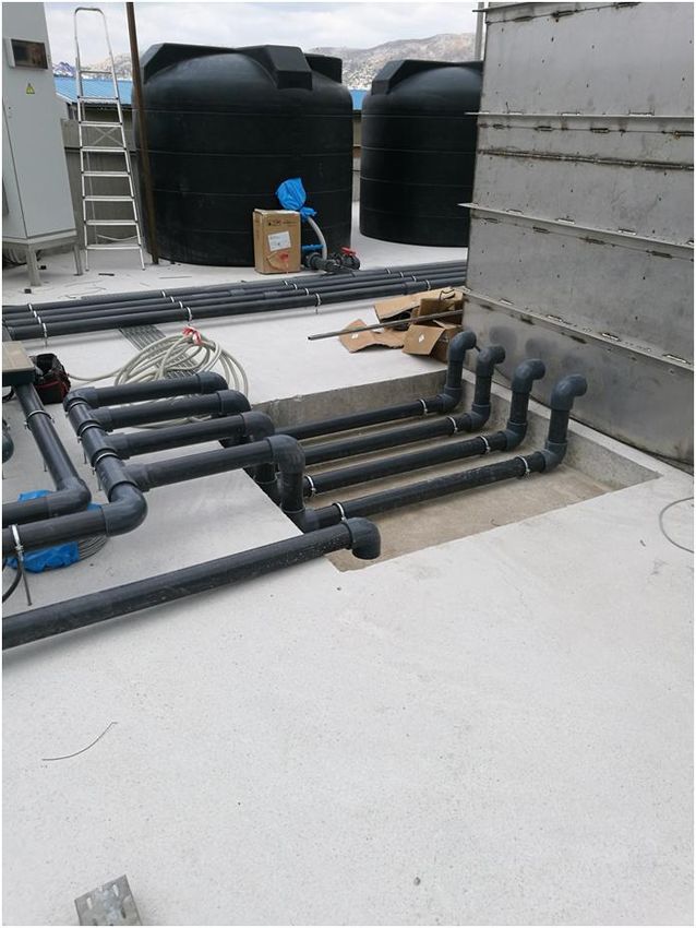
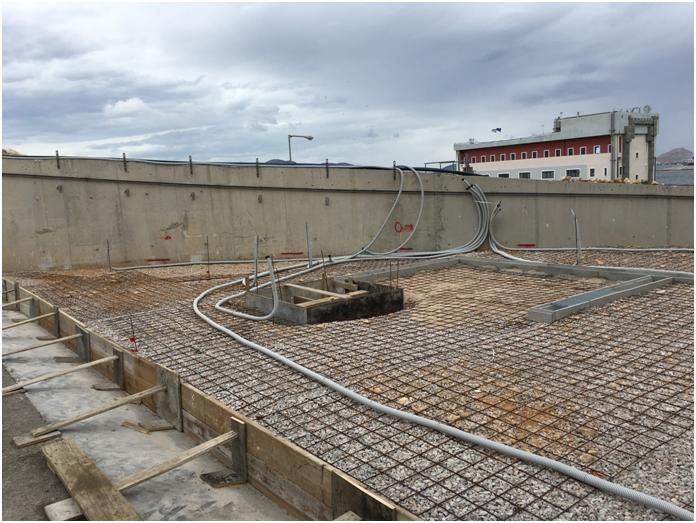
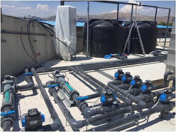
Project: No 690323

Figure 11 Major units of SMARTech 4b and their interconnections

The SBR is equipped with a mixing apparatus in order to provide a minimum mixing capacity of 8
W/m3. The mixer manufacturer is SEKO (Italy) and it is a slow speed 200rpm mixer with 220mm
propeller, stainless steel shaft and PVC body.

The effective depth of the reactor will be at least 1.5 m (during the aeration phases) in order to allow
for an oxygen transfer efficiency to the order of 8-10%. An aeration system with diffusers has been
installed in order to meet the oxygen requirements of the system. The aeration system consists of a
side channel air compressor from MAPRO International with maximum capacity of 252 m 3/h at 200
mbar and fine bubble AEROSTRIP diffusers Type T provided by Aquaconsult. The transfer efficiency
of the diffusers is in the order of 100 m3/m2 h.

The SBR will be fed with sludge liquors from the dewatering unit and from the primary sludge
thickening unit. The sludge liquors upstream the SBR will be collected in two storage tanks (one for
each type of sludge liquors). There are two transfer pumps from NETZSCH manufacturer with capacity
of 5 m3/h each, which feed the storage tanks in automatic mode, in order to keep the necessary
volume of slugde liquors in the storage tanks. Each tank provides a storage capacity of min 2 d, with
an effective volume to the order of 8 m3 each. Both storage tanks are made of polyethylene, black
color, with roof manhole. Each of these storage tanks is equipped with a submersible centrifugal
pump (two in total) from LOWARA manufacturer for continuous mixing of the content.

Each type of sludge liquors will be fed into the SBR with the use of an eccentric screw pump. The
installed feeding pump is from NETZSCH manufacturer and it is driven by VFD (frequency converter).

 SMART-Plant D3.2
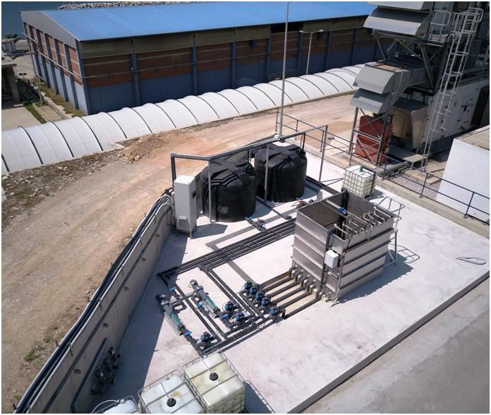
Project: No 690323

The maximum capacity of the pump is 7 m3/h. The selection of the capacity of this pump is based on:
i) the maximum daily flow rate of the sludge liquors (3 m3/d for the SL-DS and 2.65 m3/d for the SL-
PS), ii) the minimum number of 3 cycles per day and iii) the duration of fill phase of 15 min. A second
eccentric screw pump, from NETZSCH manufacturer and also driven by VFD has been installed in
order to provide decanting of treated sludge liquors from the SBR and the removal of the surplus
activated sludge as well. The waste activated sludge will be collected temporarily in a rectangular
storage tank made of polyethylene and of volume 1m3, which is sufficient for 2 days storage of sludge
removed.

A solution of acetic acid (in the form of sodium acetate) will be added to the reactor to meet the
biodegradable organic carbon requirements. The external organic carbon system consists of a
storage tank with an active volume of 1 m3 and it is sufficient for more than 7 days storage capacity.
The tank is made of polyethylene and it is placed in an appropriate leakage basin. It is equipped with
a mixer from SEKO manufacturer. A dedicated diaphragm, adjustable flow-rate dosing pump from
DOSEEURO AP manufacturer with a capacity of 200 L/h is installed in order to transfer the sodium
acetate solution from the storage tank to SBR.

It is expected that under normal conditions there will not be any need for pH control for the pilot
system. However, as the performance of especially the nitritation – denitritation processes is highly
dependent on the pH and the fact that under transient conditions (especially during start-up) there
might be a need for pH control, a pH control system has been installed in the pilot system. The pH
control system consists of an acid dosing system and a base dosing system. The acid (in the form of
sulfuric acid) dosing system consists of a storage tank with a volume of 1 m3 and a diaphragm,
adjustable flow-rate dosing pump from DOSEEURO AP manufacturer with a capacity of 50 L/h. A
separate similar dosing system is provided for the addition of the base (in the form of sodium
hydroxide). Both chemicals storage tanks are placed in a leakage basin.

The SBR is equipped with a piezoelectric level transmitter from ENDRESS+HAUSER company and
several analytical field instruments such as pH, ORP, DO, Temperature, Conductivity, NH4-N, NO2-
N/NOx-N from the WTW company. All the instrumentation will be collected in a common controller

 SMART-Plant D3.2
Project: No 690323

WTW MIQ, which will be interconnected with PLC via Profibus DP interface. All the storage tanks will
be equipped with suitable level switches.

All electrical and automation equipment, including motor starters, variable frequency drives and PLC,
have been installed into a stainless steel IP55 enclosure (2000x600x600mm) from SABO
manufacturer, forming the Motor Control Center (MCC) of the pilot plant system. The electric power
supply is at 400VAC/3–phase and the control voltage at 24VDC. The process automation (e.g. feeding,
aeration, decanting, was, chemical dosing) will be carried out in automatic mode by the CPU PLC but
there is also an HMI device (touch panel) for controlling the equipment manually and monitoring all
measured values from instrumentation locally. Finally, the MCC will be ready for interconnection to
an external PC for data acquisition.

3.2 List of the electromechanical equipment

The technical specifications of the major units and the electro-mechanical equipment installed at
the site are presented in Table 3.1.

 SMART-Plant D3.2
Project: No 690323

Table 9 Major units and specifications of the electro-mechanical equipment

 SMART-Plant D3.2                                                                                 Page 36
Project: No 690323

SMART-Plant D3.2                        Page 37
Project: No 690323

SMART-Plant D3.2                        Page 38
Project: No 690323

3.3 Practical instructions for the operation of SMARTech 4B

The operation of SMARTech 4B includes a series of actions and settings which can be divided in the
following categories:

•   Preparation of chemicals to be dosed in the reactor
•   Selection of the automation mode and definition of the set points
•   Calibration of on-line probes

Preparation of chemicals

Three types of chemicals will be used during the operation of SMARTech 4B: the substrate, the acid
and the base for pH control. Among these the acid-base chemicals will be supplied as ready to use
solutions with the already specificed characteristics and therefore no specific actions will be needed
from the operators of the system. The only care will be to send a notice for refill the chemicals tanks
upon signal of low level.

Substrate as sodium acetate will be dosed to the reactor automatically. The preparation of the
solution in the respective tank will be undertaken by the operator of the system. The solution wiil be
prepared by adding sodium acetate powder to the tank in order to reach an acetic acid content of
200 kg/m3.

Selection of automation mode

SMARTech 4b is equipped with online monitoring meters and a programmable logic controller (PLC)
which will provide operational flexibility and applicability of different control strategies.

Online probes of dissolved oxygen, pH, temperature, conductivity, oxidation-reduction potential,
NH4-N, NOx and a level meter have been installed into the surface of SBR unit and real time
information on the performance of the system will be obtained and transferred to the online
controller every 1 minute. The PLC is interconnected to an external PC for data acquisition.

 SMART-Plant D3.2                                                                          Page 39
Project: No 690323

All the major units of the electro-mechanical equipment such as the SBR mixer apparatus and the
mixing devices of storage tanks, feeding, dosing and decanting pumps and the air blower are
connected to the PLC which control their operation according to predefined parameters or schedule.

The main operational strategy that will be established is based on time schedule and online sensors
measurements. More specifically, every SBR cycle has a number of distinct phases. For each phase a
variety of functions and processes have been programmed under the regulations of the PLC according
to the automation plan. Table 10 describes the basic features of the automation to control the
operation pf the system.

Table 10 Basic features of automation in the operation of pilot plant system.

  Operation phase              Parameter    that   defines   the Equipment in working mode
                               phase duration according to PLC during this phase controlled by
                               design                              PLC
  Filling                      Timer or/and Level meter            SBR mixing device
                                                                   Sludge liquors feeding pumps
  Anaerobic phase              Timer                               SBR mixing device
  (1-2 phases during each                                          pH adjustment system
  cycle)                                                           acid/base dosing pumps
  Aerobic phase                Main operation: Timer or/and Air blower
  (1-3 phases during each NH4-N sensor measurements                pH adjustment system
  cycle)                       Alternativelly: pH set point or pH acid/base dosing pumps
                               slope                               Control of blower flow rate
  Anoxic phase                 Main operation: Timer or/and SBR mixing device
  (1-3 phases during each NOx sensor measurements                  Substrate feeding pumps
  cycle)                       Alternativelly: ORP slope or pH pH adjustment system
                               set point or pH slope               acid/base dosing pumps
  Settling                     Timer                               -

 SMART-Plant D3.2                                                                      Page 40
Project: No 690323
Decanting Selected valve of decanding Decanting pump
pump
SAS removal Selected valve of decanting pump Decanting pump
SBR mixing device
Based on the design of the automation system the operator is able to choose the number of each
phase (e.g. anaerobic, anoxic, aerobic) during each cycle as well as their sequence. The maximum
number of process functions/phases that can be selected in each cycle is eight (two anaerobic, three
anoxic and three aerobic).
Filling phase is starting upon setting the feeding pump on. The duration of the feeding phase is
primarily based on the set point of the level meter. For safety reasons the maximum duration of this
phase can also be regulated by a timer.
The duration of the anaerobic phase is primarily regulated by a timer. During this phase, the PLC will
set up the SBR mixing system and if necessary will control the pH adjustment system providing acid
or base solution from the storage tanks using two dosing pumps. It is expected that under transient
conditions and especially during start-up there will be a need for pH control to the desired set points
by providing sulfuric acid or sodium hydroxide.
During the aerobic phase the PLC will activate the aeration system while the mixing system will
ceased operation as adequate mixing will be provided by the diffusers. The air flow rate provided by
the blower will be regulated according to the desired set point of dissolved oxygen in the reactor.
The duration of the aerated period will be controlled either by a timer or by a critical value of NH4-N
sensor (or both). The automation system provides also alternative control functions of the duration
of this phase based either on the pH set point or on pH slope. During the aerated phases pH control
can be impleened (if desired) by regulating the acid/base dosing system.
Following the aerobic phase, the anoxic phase will start with the end of aeration and the addition of
external carbon source (fiilling). In order to meet the biodegradable organic carbon requirements for
denitritation procces the automation system will be set to provide adequate volumes of primary
SMART-Plant D3.2 Page 41Project: No 690323
sludge liquor or acetate or a mix of the two substrates. A maximum of three dinstict anoxic phases
can be implemented during each cycle and their duration will be controlled by either a timer or by
reaching a pre-defined value of NOx sensor (or both). Furthermore, alternative control strategies can
also be choosen by the operator based on set points defined for ORP, pH and pH slope. During each
anoxic phase the PLC will maintain open the mixing system and will also provide pH control.
The surplus activated sludge (SAS) removal will take place either during aerobic or during anoxic
phase in the form of mixed liquor in order to keep the desried sludge age.
After the last anoxic period in each cycle, the PLC will stop the mixing system and sedimentation
phase will take place for a pre-selected time period. Every cycle will end up with decanting. The PLC
will control the volume of supernatant that the decanting pump will remove from the SBR unit either
by a timer or by the level meter measurements.
In view of the above, the operator selects the mode of automation and specifies the set points
directly on the screen pf PLC.
Calibration of on-line probes
Calibration of the on-line probes will take place on a weekly basis. In this context the operator will
collect activated sludge samples which will be analyzed for pH, conductivity, ORP, NH4-N, NO2-N, NOx-
N and the results will be compared with the on-line measurements for validation. Upon significant
deviations calibration of the on-line probes will take place.
3.1 Integrability of the Smartech 4b in existing WWTPs
Integrability issues Smartech 4b
Technical Feasibility
SMART-Plant D3.2 Page 42You can also read