Evaluation of Integrating a Molten Carbonate Fuel Cell (MCFC) with a SAGD Facility - Alberta Innovates - Energy and Environment Solutions Prepared For
←
→
Page content transcription
If your browser does not render page correctly, please read the page content below
Evaluation of Integrating a Molten
Carbonate Fuel Cell (MCFC) with a
SAGD Facility

Prepared For

Alberta Innovates – Energy and
Environment Solutions

 July 2015
205 Quarry Park Boulevard SE
Calgary, Alberta T2C 3E7
Canada
+403.258.6896 (phone)
+403.385.1543 (fax)

 Evaluation of Integrating a Molten
 Carbonate Fuel Cell (MCFC) with a
 SAGD Facility

 Prepared For

 Alberta Innovates – Energy and
 Environment Solutions

 For Jacobs Consultancy

 Neera Chawla Rich Hill

 Dieter Lamprecht Stephen Scott

 July 2015
This report was prepared based in part on information not within the control
of the consultant, Jacobs Consultancy Canada Inc. Jacobs Consultancy
has not made an analysis, verified, or rendered an independent judgment
of the validity of the information provided by others. While it is believed that
the information contained herein will be reliable under the conditions and
subject to the limitations set forth herein, Jacobs Consultancy does not
guarantee the accuracy thereof. Use of this report or any information
contained therein shall constitute a release and contract to defend and
indemnify Jacobs Consultancy from and against any liability (including but
not limited to liability for special, indirect or consequential damages) in
connection with such use. Such release from and indemnification against
liability shall apply in contract, tort (including negligence of such party,
whether active, passive, joint or concurrent), strict liability or other theory of
legal liability, provided, however, such release limitation and indemnity
provisions shall be effective to, and only to, the maximum extent, scope, or
amount allowed by law.

This document, and the opinions, analysis, evaluations, or recommenda-
tions contained herein are for the sole use and benefit of the contracting
parties. There are no intended third party beneficiaries, and Jacobs
Consultancy shall have no liability whatsoever to third parties for any
defect, deficiency, error, omission in any statement contained in or in any
way related to this document or the services provided.

Table of Contents

A Executive Summary ........................................................................................................................ A-1

 Background .......................................................................................................................... A-2
 Problem Statement .......................................................................................................................... A-2
 Study Highlights .......................................................................................................................... A-3
 Study Basis .......................................................................................................................... A-4
 Methodology .......................................................................................................................... A-6
 Results .......................................................................................................................... A-7
 Qualitative Comments Regarding Other SAGD CPF Configurations................................................ A-9
 Findings and Recommendations ..................................................................................................... A-11

B Study Background .......................................................................................................................... B-1

 Study Objectives .......................................................................................................................... B-2
 Configuration Options ........................................................................................................................ B-3
 Basis and Assumptions ..................................................................................................................... B-4
 GHG Emissions Basis .......................................................................................................... B-5
 Overall Methodology .......................................................................................................................... B-6
 Operating Cost Estimate Basis and Methodology ............................................................................. B-6
 SAGD CPF Capital Cost Estimate Basis and Methodology .............................................................. B-7
 MCFC+CO2 Capital Cost Estimate Basis and Methodology ............................................................. B-8
 Other Cost Estimate Information ....................................................................................................... B-9
 Direct Field Costs ................................................................................................................. B-9
 Indirect Field Costs ............................................................................................................. B-10
 Contingency ........................................................................................................................ B-11
 Excluded Costs ................................................................................................................... B-12

C Case Descriptions .......................................................................................................................... C-1

 SAGD CPF Process Description ....................................................................................................... C-2
 Group 1 .......................................................................................................................... C-3
 Groups 2 and 3 ..................................................................................................................... C-4
 MCFC+CO2 Capture and Compression Process Description ........................................................... C-6
 Plant Configuration ............................................................................................................... C-6
 Process Description .............................................................................................................. C-7

D Results .......................................................................................................................... D-1

 Power, Water, and Heat Integration .................................................................................................. D-2
 Performance Results ......................................................................................................................... D-8
 Total GHG Emissions ........................................................................................................... D-9
 Natural Gas Consumption .................................................................................................. D-10
 Power ........................................................................................................................ D-10
 Make-up Water Usage ........................................................................................................ D-11
 Operating Costs .................................................................................................................. D-12
 Capital Costs ...................................................................................................................... D-13
 Comparison to Phase 1 ...................................................................................................... D-14
E Findings and Recommendations ................................................................................................... E-1

 Findings .......................................................................................................................... E-2
 Recommendations .......................................................................................................................... E-4

 Tables

B-1 Produced and Make-up Water Qualities .............................................................................. B-5
B-2 Commodity Prices ................................................................................................................ B-7
D-1 Integration Options ............................................................................................................... D-5
D-2 Group 1 Cases Comparison ................................................................................................. D-8
D-3 Case 1b – Total GHG Emissions ......................................................................................... D-9
D-4 Performance Relative to Phase 1 ....................................................................................... D-15

 Figures

A-1 SAGD CPF Configuration .................................................................................................... A-5
A-2 Simplified Integration Diagram ............................................................................................. A-6
A-3 CAPEX ......................................................................................................................... A-7
A-4 OPEX .......................................................................................................................... A-8
A-5 GHG Emissions .................................................................................................................... A-8
A-6 Case 2a Configuration .......................................................................................................... A-9
A-7 Case 3a Configuration ........................................................................................................ A-10
C-1 Case 1a (SAGD with WLS + OTSG) .................................................................................... C-3
C-2 Case 1b (WLS + OTSG + MCFC+CO2) ............................................................................... C-4
C-3 Case 2a (Evaporator + Drum Boiler) .................................................................................... C-5
C-4 Case 3a (WLS + Cogen + OTSG) ........................................................................................ C-5
C-5 MCFC .......................................................................................................................... C-7
D-1 MCFC Block Flow Diagram .................................................................................................. D-3
D-2 Option 2 – Heat Produced Water ......................................................................................... D-4
D-3 Option 3 – Heat BFW ........................................................................................................... D-4
D-4 DCC Configuration for Option 1............................................................................................ D-6
D-5 MCFC Water Routing into SAGD Facility ............................................................................. D-6
D-6 Case 1a Overall Balance ...................................................................................................... D-7
D-7 Case 1b Overall Balance ...................................................................................................... D-7
D-8 Total GHG Emissions ........................................................................................................... D-9
D-9 Natural Gas Consumption .................................................................................................. D-10
D-10 Power Import/Export ........................................................................................................... D-11
D-11 Make-up Water Usage ........................................................................................................ D-12
D-12 Total Operating Costs ......................................................................................................... D-13
D-13 Total Capital Costs ............................................................................................................. D-14
E-1 Case 2a Configuration .......................................................................................................... E-3
E-2 Case 2b Configuration .......................................................................................................... E-3

 Appendices

 Appendix 1 – DBM
 Appendix 2 – IEs and BFDs
 Appendix 3 – Utility Summaries
Section A.

Executive Summary

This document and the opinions, analysis, evaluations, or recommendations contained herein are for the sole use and benefit of the contracting parties.
There are no intended third party beneficiaries, and Jacobs Consultancy Inc. shall have no liability whatsoever to third parties for any defect, deficiency, A-1
error, or omission in any statement contained in or in any way related to this document or the services provided.
Background
Alberta Innovates – Energy and Environment Solutions (“AI-EES”) and an industry consortium
of three companies commissioned Jacobs Consultancy Canada Inc. (“Jacobs Consultancy”) to
perform an assessment of the benefits of integrating a Steam Assisted Gravity Drainage
(“SAGD”) central processing facility (“CPF”) with a molten carbonate fuel cell coupled with CO2
capture and compression (“MCFC+CO2”). The integration assessment (the “Study”) is a follow-
up to a techno-economic comparison study (“Phase 1”) performed by Jacobs Consultancy in
2013 that found that the MCFC+CO2 process had the potential to capture and compress CO2
with lower costs of captured and avoided CO2 than competing commercial amine-based
technologies.

AI-EES directed the Study, which was funded and directed by a Steering Committee consisting
of the following companies:

 • AI-EES (Sponsor and Steering Committee Chair)

 • MEG Energy

 • Shell Canada

 • Suncor Energy (“Suncor”)

Fuel Cell Energy (“FCE”) has developed a technology configuration using MCFC called
Combined Electric Power and Carbon Dioxide Separation (“CEPACS”) that utilizes the MCFC to
concentrate CO2 which is later purified and compressed, forming a complete MCFC plus CO2
concentration and compression system that for the purposes of this Study will be referred to
interchangeably as MCFC or MCFC+CO2. We have used FCE’s technology as the
representative MCFC+CO2 for the purposes of this Study.

This report documents our methodology, basis, findings, and recommendations for the Study.

Problem Statement
Inherent in any SAGD complex is the need to produce heat to generate steam for the production
of bitumen. The amount of steam required can vary between two barrels of cold water
equivalent for every barrel of oil to four or more, depending on the reservoir. Two primary
methods of generating the heat are used today:

 • The first is straightforward steam generation using a boiler (usually once-through steam
 generator) with natural gas and produced gas as the fuel.

This document and the opinions, analysis, evaluations, or recommendations contained herein are for the sole use and benefit of the contracting parties.
There are no intended third party beneficiaries, and Jacobs Consultancy Inc. shall have no liability whatsoever to third parties for any defect, deficiency, A-2
error, or omission in any statement contained in or in any way related to this document or the services provided.
• The other method is generically referred to as combined heat and power (“CHP”), and
 typically involves the use of a gas turbine to generate power and the use of waste heat
 from the turbine plus supplemental duct firing to generate steam. Power generation is
 usually more than required by the SAGD plant, so the excess is sold as an export to the
 “grid” or another power consumer.

One of the key environmental issues plaguing both types of steam production is the generation
of CO2. Commercially available technologies to capture CO2 are expensive, have high operating
costs, and incur parasitic losses that generate additional CO2. The result is that the avoided cost
of capture can be more than $150/tonne of CO2.

In Phase 1, we found that MCFC+CO2 had the potential to capture and compress CO2 from a
SAGD plant at a lower cost than commercially available amine-based technologies.

Therefore, the objective of the Study was to determine the benefits of integrating MCFC
technology and CO2 capture and compression with a Warm Lime Softening (“WLS”) / Once-
Through Steam Generator (“OTSG”) based SAGD CPF via the following metrics:

 • Energy efficiency

 • Make-up water intensity

 • Direct / indirect CO2 emitted and captured

 • Capital and operating costs

Based on the analysis above, we were also asked to provide comments regarding the
integration of the MCFC+CO2 facility into SAGD CPF using evaporators and drum boilers for
water treatment and steam generation, respectively and a SAGD CPF generating steam and
power via a combination of conventional cogen and boilers.

Study Highlights
The following list summarizes the highlights of the Study:

 • Integrating streams between a SAGD CPF and MCFC+CO2 unit needs to be focused on
 improving the efficiency of the SAGD plant to reduce capital costs and operating costs,
 because it is less expensive to reduce the generation of CO2 than to generate it and then
 capture CO2.

This document and the opinions, analysis, evaluations, or recommendations contained herein are for the sole use and benefit of the contracting parties.
There are no intended third party beneficiaries, and Jacobs Consultancy Inc. shall have no liability whatsoever to third parties for any defect, deficiency, A-3
error, or omission in any statement contained in or in any way related to this document or the services provided.
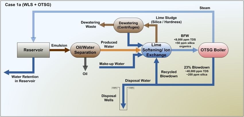
• Integration streams between the SAGD CPF and MCFC+CO2 are limited to flue gas
 from the SAGD to the MCFC+CO2 and water, heat, and power from the MCFC+CO2 unit
 back to SAGD.

 • Both the SAGD plant and the MCFC+CO2 unit are extensively heat integrated on an
 individual basis; therefore, the potential for economical heat integration between the
 MCFC+CO2 unit and SAGD is limited.

 • Water and power from the MCFC+CO2 are readily integrated into the SAGD CPF flow
 scheme with very little change in the process flow of the SAGD CPF.

Study Basis
The request for proposal originally envisioned evaluating the integration potential of the
MCFC+CO2 unit with three different SAGD CPF configurations based on water treatment and
steam generation technology differences. However, to reduce costs, the evaluation was
narrowed to a single SAGD CPF flow-scheme (Group 1) plus any qualitative comments
regarding integration with the other two SAGD CPF configurations (Groups 2 and 3) if
applicable. For the purposes of this report, Case 1a refers to the Group 1 configuration using
warm lime softening (WLS) and once-through steam generators (OTSG) without CO2 capture,
while Case 1b refers to the same SAGD CPF configuration but includes MCFC+CO2 for CO2
capture.

From a SAGD perspective, the Study basis was the same as Phase 1. The most notable
difference is that the emulsion temperature to the CPF as reflected in the Request for Proposal
(RFP) was lower than in Phase 1.

The Steering Committee decided at the kick-off meeting to size the MCFC+CO2 unit to handle
the entire flue gas stream and capture and compress 90 percent of the CO2 in the flue gas.

The SAGD CPF configuration evaluated is represented in Figure A-1 as a conceptual flow
diagram (“CFD”). The SAGD flow scheme is conventional. The first step is oil water separation
of the incoming emulsion. The produced water is de-oiled, treated with a warm lime softener
and ion exchange. Make-up water is added and treated along with the produced water. The
combined treated water becomes boiler feed water. The boiler feed water is heated then fed at
high pressure to the OTSG, which produces steam at 77 percent quality. The blowdown is
recycled back through water treatment to a recycle limit of 65 percent. The excess blowdown is
cooled, treated for silica, and disposed via deep well injection.

This document and the opinions, analysis, evaluations, or recommendations contained herein are for the sole use and benefit of the contracting parties.
There are no intended third party beneficiaries, and Jacobs Consultancy Inc. shall have no liability whatsoever to third parties for any defect, deficiency, A-4
error, or omission in any statement contained in or in any way related to this document or the services provided.
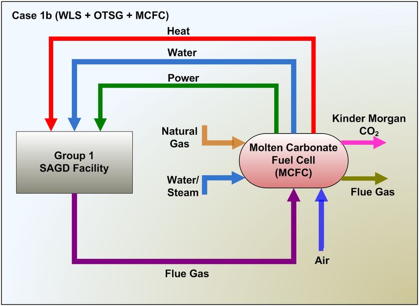
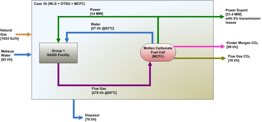
Figure A-1.
Case 1a - SAGD CPF Configuration

Conceptually, the integration of the SAGD CPF (represented in Figure A-1) with the MCFC+CO2
is shown in Figure A-2. As discussed above, flue gas from the SAGD CPF is routed to the
MCFC+CO2 system for concentration and compression. Power, water, and heat from the
MCFC+CO2 are then available for use by the SAGD CPF.

This document and the opinions, analysis, evaluations, or recommendations contained herein are for the sole use and benefit of the contracting parties.
There are no intended third party beneficiaries, and Jacobs Consultancy Inc. shall have no liability whatsoever to third parties for any defect, deficiency, A-5
error, or omission in any statement contained in or in any way related to this document or the services provided.
Figure A-2.
 Case 1b - Simplified Integration Diagram

Methodology
At a high level, Jacobs Consultancy performed the following main activities for Cases 1a and
1b:

 1. Determined the integration basis

 2. Brainstormed integration opportunities

 3. Evaluated the options

 4. Selected the optimum integration option

 5. Finalized the high-level material balances

 6. Estimated the Capex and Opex for the selected option

 7. Tabulated results

This document and the opinions, analysis, evaluations, or recommendations contained herein are for the sole use and benefit of the contracting parties.
There are no intended third party beneficiaries, and Jacobs Consultancy Inc. shall have no liability whatsoever to third parties for any defect, deficiency, A-6
error, or omission in any statement contained in or in any way related to this document or the services provided.
Results
Our analysis showed that it was only economic to integrate power and water from the
MCFC+CO2 into the SAGD CPF configuration. Heat produced by the MCFC+CO2 was not at a
temperature sufficient to invest any capital for using the heat at the SAGD CPF. Therefore, only
the water and power were used at the SAGD CPF, which reduced the amount of makeup water
required, met all the power requirements for the SAGD facility—including the production well
pumps—and converted the whole facility into a net power exporter.

Capital costs (Capex) increased by about $450 MM for the addition of the MCFC+CO2 on the
SAGD CPF, with 99 percent of the additional costs resulting from the fuel cells and carbon
capture and compression equipment. Costs to integrate the power and water are estimated to
be less than $10 MM. Figure A-3 summarizes the capital costs for both the SAGD CPF and the
SAGD CPF with the integrated MCFC+CO2.

Figure A-3.
Capex

 Total Capex
 1,400
 $1,289 MM

 1,200

 1,000
 $832 MM
 $MM

 800

 600

 400

 200

 0
 Case 1a Case 1b

As shown in Figure A-4, estimated operating costs (Opex) actually decreased with the
integration of the MCFC+CO2 as a result of the 51 MW of power exported to the grid at a price
of $90/MWhr. The estimated operating costs were $115 MM/yr for the SAGD complex and $108
MM/yr with the integration of the MCFC+CO2 plant, even with fixed operating costs increasing

This document and the opinions, analysis, evaluations, or recommendations contained herein are for the sole use and benefit of the contracting parties.
There are no intended third party beneficiaries, and Jacobs Consultancy Inc. shall have no liability whatsoever to third parties for any defect, deficiency, A-7
error, or omission in any statement contained in or in any way related to this document or the services provided.
an estimated $23 MM/yr due to the increased capital cost and an increase in natural gas usage
with a cost of $22 MM/yr.

Figure A-4.
Opex

 Totel Opex ($MM/yr) Other
 150.00
 $12.3 MM/yr Power
 125.00 NG
 $12.9 MM/yr
 100.00 $10.9 MM/yr $84.3 MM/yr
 Fixed
 75.00
 $MM/yr

 $62.3 MM/yr
 50.00
 25.00 $52.0 MM/yr
 $29.1 MM/yr
 0.00
 -25.00 $-40.6 MM/yr

 -50.00
 Case 1a Case 1b
 Note: CO2 credits/debits not included

Figure A-5.
GHG Emissions

 Total GHG Emissions
 2,194 t/d
 2,250
 GHG Emissions (Tonnes/day)

 2,000
 1,750
 1,500
 1,250
 1,000
 750
 500 271 t/d
 250
 0
 Case 1a Case 1b (0t/MWh)

This document and the opinions, analysis, evaluations, or recommendations contained herein are for the sole use and benefit of the contracting parties.
There are no intended third party beneficiaries, and Jacobs Consultancy Inc. shall have no liability whatsoever to third parties for any defect, deficiency, A-8
error, or omission in any statement contained in or in any way related to this document or the services provided.
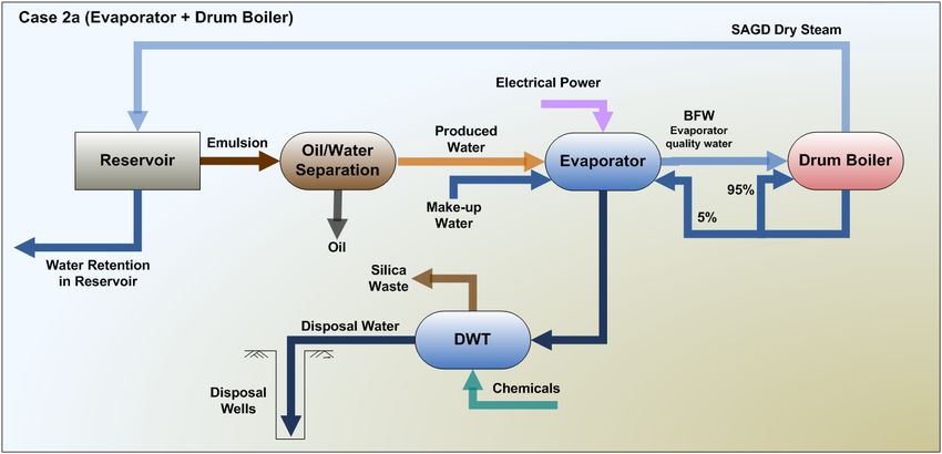
The primary reason for integrating the MCFC+CO2 facility in a SAGD CPF is to reduce the
amount of GHG emissions, assuming that the compressed and concentrated CO2 is
sequestered. In this regard, the MCFC+CO2 has a large impact on GHG emissions. As shown in
Figure A-5, where we assume 90 percent capture, dilute CO2 emitted by a SAGD CPF is
reduced more than 1,920 tonnes/day, even without any GHG credits for the power exported to
the grid. This case is identified as Case 1b (0t/MWh) which shows zero tonnes per mega-watt
hour used for power export.

Qualitative Comments Regarding Other SAGD
CPF Configurations
As indicated in the objectives, we were asked to provide qualitative comments regarding the
integration of the MCFC+CO2 into other water treatment and steam generation configurations
for the SAGD CPF, based on our analysis of the WLS + OTSG SAGD configuration. The two
configurations were labeled Group 2 and Group 3. Simplified representations of each are shown
in Figures A-6 and A-7.

Figure A-6.
Case 2a Configuration

This document and the opinions, analysis, evaluations, or recommendations contained herein are for the sole use and benefit of the contracting parties.
There are no intended third party beneficiaries, and Jacobs Consultancy Inc. shall have no liability whatsoever to third parties for any defect, deficiency, A-9
error, or omission in any statement contained in or in any way related to this document or the services provided.
Figure A-7.
Case 3a Configuration

Our comments regarding the integration of the MCFC+CO2 into an evaporator+drum boiler
SAGD CPF represented in Figure A-6 are as follows:

 • From a SAGD perspective, drum boilers offer slightly better efficiency than OTSG, so
 natural gas combustion and therefore flue gas production are lower. Evaporator-based
 water treatment uses more power than WLS, so the configuration consumes more
 power. In addition, make-up water is lower because the disposal volume is less. The
 heat exchange scheme is similar to Group 1.

 • The MCFC+CO2 system is slightly smaller due to decreased flue gas

 • Therefore, in our opinion:

 o Power consumption on-site increases and MCFC production is lower, so the
 amount of power exported goes down.

 o Water requirements from the CPF are lower but with reservoir retentions close to
 10 percent, all the MCFC+CO2 water can be utilized by the CPF and make-up
 water is lower than in Group 1.

 o There is no change in heat integration. The level of heat produced by the MCFC
 is too low to be used economically.

This document and the opinions, analysis, evaluations, or recommendations contained herein are for the sole use and benefit of the contracting parties.
There are no intended third party beneficiaries, and Jacobs Consultancy Inc. shall have no liability whatsoever to third parties for any defect, deficiency, A-10
error, or omission in any statement contained in or in any way related to this document or the services provided.
Our comments regarding the integration of the MCFC+CO2 into a cogen + OTSG SAGD CPF
represented in Figure A-7 are as follows:

 • The SAGD CPF has more flue gas because of the cogen. There will be additional heat,
 O2 and NOx in the flue gas. However, make-up water requirements should be the same
 as Group 1 and the heat integration is similar to Group 1. The biggest change is that the
 SAGD CPF is a net exporter of power before the addition of the MCFC+CO2

 • The MCFC+CO2 system is larger because the quantity of flue gas and the flue gas
 cooling requirements increased due to higher temperature flue gas. The fuel cell,
 however, should be fine with increases in O2 and NOx.

 • Therefore, in our opinion:

 o The site becomes an even larger exporter of power with the addition of the
 MCFC+CO2. Infrastructure costs associated with switching from a net importer
 to net exporter of power may be lower.

 o The complex may be long on water due to increased water from the MCFC+CO2.

 o Similar to Group 1, heat integration is likely to have little value.

Findings and Recommendations
In our opinion, integrating an MCFC+CO2 facility into a SAGD CPF does the following:

 • Reduces dilute CO2 emission by 88 percent not including GHG credits for exporting 51
 MW of power to the grid.

 • Increases capital cost by over 50 percent compared to the cost of the SAGD CPF
 primarily due to the cost of installing the MCFC+CO2 facility. Integration costs by
 themselves are less than $10 MM.

 • Reduces operating costs by 6 percent assuming that the power can be sold to the grid at
 $90/MWhr and does not include GHG credits.

 • Reduces make-up water requirements and eliminates the need for purchased power for
 the SAGD CPF.

 • Is enabled by the uncomplicated nature of integrating power and water. Integrating the
 heat from the MCFC+CO2 in the SAGD complex has little benefit.

Integrating the MCFC+CO2 represented in the Study as the Combined Electric Power and
Carbon Dioxide Separation (“CEPACS”) by Fuel Cell Energy into a SAGD CPF is economically
limited to power and water, and therefore presents very little technical risk. In addition, the

This document and the opinions, analysis, evaluations, or recommendations contained herein are for the sole use and benefit of the contracting parties.
There are no intended third party beneficiaries, and Jacobs Consultancy Inc. shall have no liability whatsoever to third parties for any defect, deficiency, A-11
error, or omission in any statement contained in or in any way related to this document or the services provided.
MCFC itself is commercialized. The addition of an MCFC+CO2 system into a SAGD CPF,
however, does present the following primary risks:

 • Capital cost: Installing an MCFC+CO2 of this size has not been done. In addition, there
 are capital cost risks associated with installing a plant of this magnitude in northern
 Alberta.

 • Reliability, operability, and maintenance costs: Although most of the components of the
 MCFC+CO2 are commercial or near commercial, the reliable operation and maintenance
 costs resulting from an installation of this size in northern Alberta are risks. There are
 likely to be unforeseen challenges regarding the operation and maintenance of this type
 of facility.

Therefore, in our opinion, this Study supports the findings from Phase 1, in that the MCFC+CO2
addition to SAGD CPF can offer substantially lower costs of capture than commercially available
amine systems and is a promising technology for CO2 capture and compression for the
purposes of producing CO2 for EOR or sequestration. We recommend in the near term:

 • Feasibility studies to investigate the benefits of MCFC+CO2 for capturing CO2 from the
 flue gas of Steam Methane Reformers (SMR) and smaller fired heaters present in
 upgraders and refineries.

 • A detailed study in conjunction with Fuel Cell Energy focused on the trade-offs of
 increasing the amount and temperature of the heat generated by the fuel cell for the
 purposes of reducing natural gas consumption for SAGD.

 • A design study to determine location, feasibility, and estimated capital cost of an
 MCFC+CO2 demonstration facility in Alberta to confirm reliability, operability, and
 commercial readiness, and to highlight other development issues.

 • A study to investigate the economics and emissions resulting from the co-production of
 hydrogen with an MCFC+CO2. The MCFC operating in Orange County, CA is
 configured to produce and concentrate hydrogen in addition to generating power.

This document and the opinions, analysis, evaluations, or recommendations contained herein are for the sole use and benefit of the contracting parties.
There are no intended third party beneficiaries, and Jacobs Consultancy Inc. shall have no liability whatsoever to third parties for any defect, deficiency, A-12
error, or omission in any statement contained in or in any way related to this document or the services provided.
Section B.

 Study Background

This document and the opinions, analysis, evaluations, or recommendations contained herein are for the sole use and benefit of the contracting parties.
There are no intended third party beneficiaries, and Jacobs Consultancy Inc. shall have no liability whatsoever to third parties for any defect, deficiency, B-1
error, or omission in any statement contained in or in any way related to this document or the services provided.
The Alberta government and the oil sands industry have collectively been committed to
evaluating techniques in efforts to reduce greenhouse gas (“GHG”) emissions from oil sands
production. The development of low-cost carbon capture technologies has been a prime focus
to bringing producers closer in reaching Alberta’s GHG emission reduction goals. As a part of
this initiative, Jacobs Consultancy completed the Phase 1 Study “Evaluation of Electrochemical
Membranes for Carbon Capture at a SAGD Facility” in 2012, which examined the potential of
combining Electrochemical Membrane (“ECM”)—generically referred to as Molten Carbonate
Fuel Cell (“MCFC”)—for carbon capture from SAGD operations. The study showed significantly
lower costs of capture for this technology than for commercial amine-based systems. Due to the
encouraging results, AI-EES and a number of oil sands companies were interested in evaluating
the integration of MCFC into a SAGD CPF as opposed to just adding the MCFC to the back end
of the SAGD CPF.

Fuel Cell Energy (“FCE”) has developed a technology configuration using MCFC called
Combined Electric Power and Carbon Dioxide Separation (“CEPACS”) that utilizes the MCFC to
concentrate CO2 which is later purified and compressed, forming a complete MCFC plus CO2
concentration and compression system that for the purposes of this Study will be referred to
interchangeably as MCFC or MCFC+CO2.

Study Objectives
The objective of the Study was to determine the benefits of integrating MCFC technology and
CO2 capture and compression with a Warm Lime Softening (“WLS”) / Once-Through Steam
Generator (“OTSG”) based SAGD CPF via the following metrics:

 • Energy efficiency

 • Make-up water intensity

 • Direct / indirect CO2 emitted and captured

 • Capital and operating costs

Based on the analysis above, we were also asked to provide comments regarding the
integration of the MCFC+CO2 facility into SAGD CPF using evaporators and drum boilers for
water treatment and steam generation, respectively, and a SAGD CPF generating steam and
power via a combination of conventional cogen and boilers.

This document and the opinions, analysis, evaluations, or recommendations contained herein are for the sole use and benefit of the contracting parties.
There are no intended third party beneficiaries, and Jacobs Consultancy Inc. shall have no liability whatsoever to third parties for any defect, deficiency, B-2
error, or omission in any statement contained in or in any way related to this document or the services provided.
Configuration Options
The SAGD CPF configurations were split into three Groups as follows:

 • Group 1

 a. Case 1a: Warm Lime Softener (“WLS”) + OTSG

 Case 1a is the reference case of a SAGD production facility that employs WLS
 for water treatment and OTSG to generate steam by burning natural gas and
 imports electricity from the grid.
 b. Case 1b: WLS + OTSG + MCFC+CO2 capture and compression

 Case 1b is the case of a SAGD facility that employs WLS for water treatment and
 OTSG to generate steam by burning natural gas. The power is generated by
 MCFC. MCFC is used to separate OTSG CO2 and is integrated with the whole
 SAGD system. The captured CO2 is compressed to Kinder Morgan pipeline
 specs.

Based on the results found for the Group 1 cases, qualitative comments regarding integration
for Groups 2 and 3 are found in Section E. Groups 2 and 3 are summarized below.

 • Group 2

 a. Case 2a: Evaporator + Drum Boiler

 Case 2a is the reference case of a SAGD production facility that employs an
 evaporator for water treatment and drum boiler to generate steam by burning
 natural gas and imports electricity from the grid.
 b. Case 2b: Evaporator + Drum Boiler + MCFC+CO2 capture and compression

 Case 2b is the case of a SAGD production facility that employs an evaporator for
 water treatment and drum boiler to generate steam by burning natural gas. The
 power is generated by MCFC. MCFC is used to separate CO2 and is fully
 integrated with the whole SAGD system. The captured CO2 is compressed to
 Kinder Morgan pipeline specs.
 • Group 3

 a. Case 3a: WLS + [Cogen (50%) + OTSG (50%)]

 Case 3a is the case of a SAGD production facility that employs WLS for water
 treatment and cogeneration and OTSG to generate steam by burning natural gas.
 Cogeneration (“Cogen”) and OTSG 50:50 split refers to steam, each to meet 50
 percent total steam demand. Power is generated by the gas turbine generator
 (“GTG”) part of Cogen.

This document and the opinions, analysis, evaluations, or recommendations contained herein are for the sole use and benefit of the contracting parties.
There are no intended third party beneficiaries, and Jacobs Consultancy Inc. shall have no liability whatsoever to third parties for any defect, deficiency, B-3
error, or omission in any statement contained in or in any way related to this document or the services provided.
b. Case 3b: WLS + [Cogen (50%) + OTSG (50%)] + MCFC+CO2 capture and
 compression

 Case 3b is the case of a thermal in-situ production facility that employs WLS for
 water treatment and cogeneration and OTSG to generate steam by burning
 natural gas. Power is generated by both the Cogen (GTG) and MCFC. MCFC is
 used to separate CO2 from a combined OTSG flue gas and Cogen flue gas.
 MCFC is fully integrated with the entire SAGD surface facility and lifting system.
 The captured CO2 is compressed to Kinder Morgan pipeline specs.

Basis and Assumptions
For consistency purposes, the set of basis and assumptions developed for the Phase 1 Study
was used in this Study, with the exception of a lower produced emulsion temperature as
indicated in the request for proposal (“RFP”).. The SAGD basis is summarized as follows:

 • 33,000 barrels per calendar day (“bpcd”) SAGD production facility

 • Steam-to-oil ratio (“SOR”) = 3.0

 • Gas-to-oil ratio (“GOR”) = 5.0; produced gas will offset natural gas purchases

 • Produced Water to Steam Ratio (PWSR) = 0.9

 • Cases were based on an “Efficient SAGD Design” which includes Electrical submersible
 pumps (“ESPs”) for oil lifting, OTSG air economizer, efficient design, and minimization of
 Ethylene Glycol (“EG”)

 • OTSG steam quality = 77 percent at 100 barg

 • Imported electrical power to meet on-site power demands

 • Exported power transmission charges: 5 percent of net sales to AESO grid

 • Produced fluid at 160°C

 • De-oil process identical for the cases: free water knockout, followed by skim tank and
 Induced Gas Flotation (“IGF”), and then Oil Removal Filter (“ORF”)

 • Blowdown disposal by deep well injection

 • Air preheat with flue gas economizer is economic

 • Service factor of 94 percent

 • Send 100 percent of flue gas to MCFC; capture 90 percent of CO2 emitted from OTSG
 stack and MCFC and CO2 purification and compression

This document and the opinions, analysis, evaluations, or recommendations contained herein are for the sole use and benefit of the contracting parties.
There are no intended third party beneficiaries, and Jacobs Consultancy Inc. shall have no liability whatsoever to third parties for any defect, deficiency, B-4
error, or omission in any statement contained in or in any way related to this document or the services provided.
• CO2 that goes into pipeline is compressed to 2000 psi per Kinder Morgan specs

 • Make-up water is from a saline aquifer with total dissolved solids > 4,000 ppm. Water
 qualities for the Study are shown in Table B-1:

 Table B-1.
 Produced and Make-up Water Qualities

 Quality Units Produced Water Make-up Water
 TDS ppm 1290 6961
 Hardness ppm 14 204
 M-Alkalinity (CaCO3) ppm 173 665
 Ca ppm 4 34
 Mg ppm 1 29
 TOC ppm 300 6
 Silica ppm 188 7

 • Heat recovery and rejection assumes the following:

 o Minimum atmospheric temperature = - 40°C

 o Maximum atmospheric temperature = 40°C

 o Average atmospheric temperature = 16°C

 o Maximum temperature for disposal = 80°C

GHG Emissions Basis
Direct and indirect GHG emissions were comprised of the following:

 • In Case 1a, the direct GHG source is primarily the CO2 from the OTSGs used to produce
 steam; in Case 1b, the direct GHG source is the vented CO2 post MCFC and CO2
 capture and compression.

 • Indirect GHG emissions are comprised of the following:

 o Imported power generation at 0.66 tonne of CO2/MWh

 o Trucking of wastes at 0.018 tonne of CO2/tonne

 o Production of imported chemicals at 1 tonne of CO2/tonne of lime

 • GHG credit for exported power in the MCFC+CO2 integrated case is shown at 0.00 and
 0.66 tonne of CO2/MWh with sensitivities at 0.42 and 0.88 tonne of CO2/MWh

This document and the opinions, analysis, evaluations, or recommendations contained herein are for the sole use and benefit of the contracting parties.
There are no intended third party beneficiaries, and Jacobs Consultancy Inc. shall have no liability whatsoever to third parties for any defect, deficiency, B-5
error, or omission in any statement contained in or in any way related to this document or the services provided.
Overall Methodology
Our methodology involved the following high-level tasks:

 1. Prepare a design basis document and agree on basis and assumptions. Refer to
 Appendix 1.

 2. Brainstorm options to integrate the MCFC+CO2 into the SAGD CPF regarding heat,
 power, and water use

 3. Analyze the integration options

 4. Select an integration option for heat, water, and power

 5. Develop BFDs with the following information for the base case and selected option:

 a. Flows of key streams
 b. Utility summaries

 c. Disposal volumes

 d. GHG emissions

 e. Water use

 f. Estimated variable operating costs

 6. Estimate rough order of magnitude (“ROM”) capital costs based on the selected
 integration option. For Case 1b, the Total Installed Cost (“TIC”) of the MCFC was added
 to the TIC of the CPF to determine the total TIC.

 7. Estimate fixed costs based on 3.5 percent of the TIC for the SAGD CPF and 5 percent of
 the TIC for the MCFC+CO2 portion, which includes an allowance for periodic fuel cell
 stack replacement.

 8. Prepare comparison graphs and report findings.

 9. Based on the Group 1 analysis, provide qualitative comments regarding MCFC+CO2
 integration for Groups 2 and 3.

Operating Cost Estimate Basis and Methodology
Operating costs are a sum of both fixed and variable operating costs:

This document and the opinions, analysis, evaluations, or recommendations contained herein are for the sole use and benefit of the contracting parties.
There are no intended third party beneficiaries, and Jacobs Consultancy Inc. shall have no liability whatsoever to third parties for any defect, deficiency, B-6
error, or omission in any statement contained in or in any way related to this document or the services provided.
• Fixed operating costs include items such as operating labour, general and administrative
 expenses, maintenance, property taxes, and insurance; these are based on a factor of
 the TIC.

 • Variable costs include utilities, fresh water, chemicals, and disposal.

The commodity prices used are shown in Table B-2 below. We did not account for CO2 credits
for exported power or CO2 debits for indirect emissions associated with imported power in the
variable operating costs. The quantities of each of the commodities are presented in the Block
Flow Diagrams (“BFDs”) and Utility Summaries presented in Appendices 2 and 3 and serve as a
basis for the participating companies to perform individual economic evaluations.

 Table B-2.
 Commodity Prices

 Commodity Units Price ($ CND)
 Power $/ MWhr $90
 Gas $/ GJ $5
 Chemicals $/ m3 water $0.77
 Disposal costs including trucking $/ tonne $200
 3.5 (CPF);
 Fixed operating costs % of TIC
 5.0 (MCFC)

SAGD CPF Capital Cost Estimate Basis and
Methodology
The capital costs presented in this study represent an “unclassified” estimate with an accuracy
of +100%/-50%. The capital costs are representative only and are considered sufficient for
comparison purposes only.

For the SAGD CPF estimate, we used Jacobs’ proprietary models to estimate capital costs for
the Group 1 cases. The model includes historical information for costs and a parametric model
to represent the SAGD facility including plot plan, modules, piping details, and a representative
sized equipment list. Indirect costs, engineering, and other costs are factored off the total direct
costs. Costs for well pads, drilling and completions, gathering and steam lines, and source and
disposal water wells are not included in the capital cost estimate.

The following assumptions were used:

 • Estimates are on a 1st half 2015 basis

This document and the opinions, analysis, evaluations, or recommendations contained herein are for the sole use and benefit of the contracting parties.
There are no intended third party beneficiaries, and Jacobs Consultancy Inc. shall have no liability whatsoever to third parties for any defect, deficiency, B-7
error, or omission in any statement contained in or in any way related to this document or the services provided.
• Location: Northern Alberta

 • 100 percent Canadian sourced equipment

 • 25 percent contingency for SAGD CPF facility consistent with the accuracy level of the
 estimate

 • Escalation excluded

 • No Owner’s Cost

 • No Commissioning and Startup

MCFC+CO2 Capital Cost Estimate Basis and
Methodology
The MCFC+CO2 cost estimate was developed utilizing a combination of unit capacity factored
and budget quotes from licensors/vendors. These methods utilize historical data from plants
with similar units or equipment. For Case 1b, the TIC for the MCFC+CO2 was added to the TIC
for the CPF.

Capacity-factored estimating is based on multiplying the cost of a similar unit, for which the
direct construction costs are known from a prior project, by the ratio of the new unit's capacity to
the capacity of the known unit. Capacity ratios are adjusted by an exponent chosen on the basis
of the unit type. Adjustments are made as required to allow for differences in unit design bases,
location, and time frame.

The base estimates were developed on a United States Gulf Coast (“USGC”) during the 1st half
of 2015 time period broken down into labour, equipment, and materials. The USGC costs were
then adjusted to a local site basis using location-specific information. The site is Fort McMurray,
Alberta. The USGC to site adjustment factors include an efficiency factor applied to the
construction labour hours, use of a local construction wage rate, a 10percent increase in
equipment costs and a 17 percent increase in bulk material costs to account for winterization,
and use of local factors for estimating indirect field costs. An exchange rate of 1.2678
CAD$/US$ was utilized. These adjustments were made for units where costs were developed
by Jacobs as well as to the USGC cost data supplied by vendors.

Costs for CO2 export pipeline are not included.

The estimate includes EPC contractor profit but does not include an EPC contractor risk fee for
a Lump Sum-Turn Key estimate.

This document and the opinions, analysis, evaluations, or recommendations contained herein are for the sole use and benefit of the contracting parties.
There are no intended third party beneficiaries, and Jacobs Consultancy Inc. shall have no liability whatsoever to third parties for any defect, deficiency, B-8
error, or omission in any statement contained in or in any way related to this document or the services provided.
The capital cost estimates are comprised of the following components:

 • Direct Field Costs

 o Materials: equipment and bulk materials

 o Labour

 • Indirect Field Costs

 o Construction management

 o Temporary facilities and services

 • Home Office Costs

 • Contingency

The sum of these components is defined as the plant installed cost or EPC cost of the project
because it contains the items typically within the scope of the EPC contractor. Owner’s costs
that are typically outside of the EPC cost are discussed in a later subsection.

Other Cost Estimate Information
Direct Field Costs
Materials
Direct field material costs are the costs of the permanent physical plant facilities and include the
following elements:

 • Excavation and Civil—Includes piling, roads, asphalt paving, and clean structural fill.

 • Concrete and Fireproofing—Includes foundations, concrete structures, retaining walls,
 floor slabs, concrete area paving, and concrete fireproofing.

 • Structural Steel—Includes steel structures, pipe racks, handrails, ladders, stairs,
 platforms, and miscellaneous supports.

 • Buildings—Includes control, electrical substation, office, compressor, laboratory,
 warehouse, canteen, workshop and gatehouse buildings including framing, walls,
 exterior cladding and roofing, HVAC, electrical lighting and power, and interior fixtures
 and finishes.

 • Equipment—Includes tanks, vessels, fuel cell stacks combustion turbines, steam
 turbines, compressors, heat exchangers, heat recovery steam generators (“HRSGs”),

This document and the opinions, analysis, evaluations, or recommendations contained herein are for the sole use and benefit of the contracting parties.
There are no intended third party beneficiaries, and Jacobs Consultancy Inc. shall have no liability whatsoever to third parties for any defect, deficiency, B-9
error, or omission in any statement contained in or in any way related to this document or the services provided.
pumps, material processing equipment, material handling equipment, and miscellaneous
 equipment (e.g., filters, strainers).

 • Piping—Includes aboveground and underground pipe, fittings, valves, flanges, gaskets,
 shoes and guides, specialty items, and non-destructive examination.

 • Electrical—Includes major electrical equipment (e.g., transformers, breakers, switches,
 bus bars, etc.), power wire and cable, conduit, cable tray, push-button stations, welding
 and power receptacles, lighting, grounding, and instrument wire and cable.

 • Instrumentation—Includes process instruments, analysers, process connections, control
 house consoles, distributed control systems, and instrument mountings.

 • Paint—Includes paint and coatings for plant equipment, piping, and structures.

 • Insulation—Includes hot, cold, and personnel protection insulation for plant equipment
 and piping.

Materials costs have been adjusted for the site locations and include freight. The direct field
material costs are based on worldwide procurement of material. For that material, charges have
been included for inland freight to the shipping port, port charges, ocean freight, shipping
insurance, and inland freight to the project site. A winterisation allowance of 17 percent has
been applied to the bulk materials cost component, and a winterisation allowance of 10 percent
has been applied to the equipment except for the fuel cell stacks. As the fuel cell stacks are
located in a building, no winterization is required.

Labour
For the MCFC TIC, the direct field labour costs at the Canadian site locations were derived by
multiplying the estimates of USGC field labour man-hours by a labour efficiency factor of 1.43
with a representative field rate.

For the SAGD CPF, labour hours were estimated based on historical information related to the
amount of bulk materials such as concrete, piping, steel, and electrical cable.

Indirect Field Costs
As indicated above, indirect field costs related to camp, engineering, and consumables are
factored from the total direct labour costs.

This document and the opinions, analysis, evaluations, or recommendations contained herein are for the sole use and benefit of the contracting parties.
There are no intended third party beneficiaries, and Jacobs Consultancy Inc. shall have no liability whatsoever to third parties for any defect, deficiency, B-10
error, or omission in any statement contained in or in any way related to this document or the services provided.
Contingency
Contingency is a special monetary provision in the estimate to cover uncertainties or
unforeseeable elements of time/cost within the scope of the project. Costs associated with the
following items are included in contingency:

 • Material cost changes (other than scope changes)

 • Labour rate changes

 • Labour efficiency changes

 • Design changes (other than scope changes)

 • Schedule slippage

 • Estimate methodology inaccuracies

Contingency excludes the items listed below because, with the exception of scope changes,
they are unusual items that are not expected to occur on every project and their impacts can
vary significantly. Including contingency for all of these items would result in an exceptionally
high cost that would not represent the most likely cost for the project.

 • Scope changes

 • Changes in government regulations

 • Major design changes

 • Catastrophic events

 • Extreme weather

 • Unknown field conditions

 • Labour shortages or strikes

 • Significant exchange rate fluctuations

An overall contingency of 20 percent of the bottom line cost has been assumed for the
MCFC+CO2 and 25 percent for the SAGD CPF. Contingency has not been applied to individual
estimate components at this early stage of the project. This level of contingency is considered
an appropriate value when taking into account the extent of engineering and the factored
approach used in developing the cost estimate.

This document and the opinions, analysis, evaluations, or recommendations contained herein are for the sole use and benefit of the contracting parties.
There are no intended third party beneficiaries, and Jacobs Consultancy Inc. shall have no liability whatsoever to third parties for any defect, deficiency, B-11
error, or omission in any statement contained in or in any way related to this document or the services provided.
Excluded Costs
Excluded costs include taxes, financing fees, interest during construction, working capital, and
escalation.

This document and the opinions, analysis, evaluations, or recommendations contained herein are for the sole use and benefit of the contracting parties.
There are no intended third party beneficiaries, and Jacobs Consultancy Inc. shall have no liability whatsoever to third parties for any defect, deficiency, B-12
error, or omission in any statement contained in or in any way related to this document or the services provided.
You can also read