Technical file Oskar -10 - Smart energy systems by ratiotherm
←
→
Page content transcription
If your browser does not render page correctly, please read the page content below
Technical file
Oskar°-10
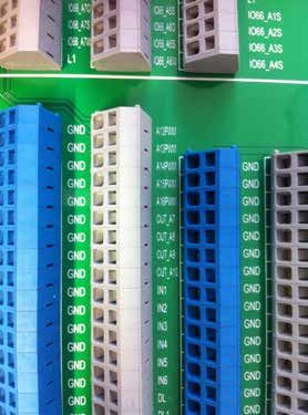
TABLE OF CONTENTS
Notes on stratified storage technology 4
General principles of design 4
Advantages and benefits 5
Notes on the documentation 6
General notes 6
Intended use 7
Guidelines, standards and laws 9
Qualification of the staff 10
Notes on safety 11
UVV, installation, changes 11
Technical data 12
Oskar-10/1,5/... 12
Technical data 14
Oskar-WPS-10/1,5/... 14
Technical data 16
Oskar-10/5,0/... 16
Technical data 18
Oskar-WPS-10/5,0/... 18
Storage tank insulation 20
2-piece 750/1000/1300 20
4-piece 2000/3000/4000 22
Assembly 24
Components 27
Ball valve set (KS2) 27
Insulating capsules - cut to length on site 28
Ball valve set on add-on manifold 1 or 2 29
Add-on distributor Terminal assignment 30
Mounting reduction set / special mounting set 31
Drinking water compaction 32
Hydraulic connection 32
Ultra fast sensor 33
Plate heat exchanger 34
Dimensions, performance data TWK-S 70 / 90 35
Dimensions, performance data TWK-S 100 36
Characteristics TWK-S 70 / 90 / 100 37
Sensor pocket 38
Positioning of sensors S3 and S11 38
Positioning of sensors S1 and S2 (hot water) 39
Turbine flow sensor - Data 40
VTY20 - Installation 41
TU_D_Oskar°-10-2021-04-wi - Irrtümer und Änderungen aller Angaben, Bilder und Zeichnungen bleiben vorbehalten.
Die Einhaltung der allgemein gültigen und anerkannten Regeln der Technik und evtl. örtlicher Vorschriften sind unbedingt einzuhalten!
2 ACHTUNG! Installation, Verdrahtung nur durch autorisiertes Fachpersonal.
TABLE OF CONTENTS
PWM control                                                                                                                            42
           TWK-S 70 / 90 / 100                                                                                                         42
Circulation station                                                                                                                    43
Drinking water cascades                                                                                                                44
           TWKK 200 (2-stage)                                                                                                          44
           TWKK 300 (3-stage)                                                                                                          45
           TWKK 400 (4-stage)                                                                                                          46
           Calculation of the hot water output                                                                                         47
           Simultaneity table                                                                                                          48
Heat meter                                                                                                                             49
           Optional retrofit TWK-S 70 / 90                                                                                             50
           Optional retrofit TWK-S 100 + cascades                                                                                      51
Heating circuits                                                                                                                       52
           Single-line pump, uncontrolled heating circuit                                                                              52
           Fixed value controlled, electronically controlled                                                                           53
Retrieval station                                                                                                                      54
           ALST-25, ALST-32                                                                                                            54
System separation                                                                                                                      55
           System separation station                                                                                                   55
District heating handover                                                                                                              56
           District heating transfer station                                                                                           56
Solarthermie                                                                                                                           58
           Solar compact station                                                                                                       58
           Hydraulic balancing                                                                                                         60
           Durchflussmengen                                                                                                            61
           Guarantee statement                                                                                                         62
           EC Declaration of Conformity                                                                                                63

TU_D_Oskar°-10-2021-04-wi - Irrtümer und Änderungen aller Angaben, Bilder und Zeichnungen bleiben vorbehalten.
Die Einhaltung der allgemein gültigen und anerkannten Regeln der Technik und evtl. örtlicher Vorschriften sind unbedingt einzuhalten!
ACHTUNG! Installation, Verdrahtung nur durch autorisiertes Fachpersonal.                                                                3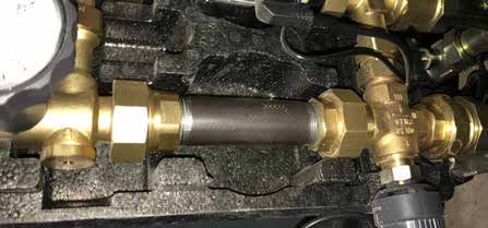
NOTES ON STRATIFIED STORAGE TECHNOLOGY
GENERAL PRINCIPLES OF DESIGN

•   Stratified storage technology thrives on temperature differences, i.e. the heat generators and heat consumers
    should be designed with a high temperature spread.

•   In general, a „pre-sorting“ of the different temperature levels is necessary by means of the corresponding
    height positioning of the supply and return connections in the stratified tank‘s stratified insert is necessary.

•   The stratified storage tank will always contain the temperatures that are supplied by the heat generators and heat
    consumers.
    This means that at the lowest point of the storage tank, the temperature of the coolest return flow of a heat con-
    sumer will be found and at the highest point, the temperature of the warmest flow of a heat generator.

•   The maximum design volume flows per connection of the respective stratified storage tank or stratified insert
    must be observed.
    This value is also a parameter/type when selecting the storage tank and stratification insert size.

•   Constantly running circulation pumps at low temperature differences should be avoided, as they destroy the strati-
    fication of the storage water.
    the stratification of the storage water. When selecting condensing boilers, particular attention must be paid to this.
    pay particular attention to this.

•   When using controlled heating circuits, 3-way mixing valves must always be provided (no 4-way mixing valves, no
    injection circuit).

•   The design of the storage volume and stratification when using solar energy is primarily based on the collector
    area or collector output.

        Example:
                                                                                        Oskar°-750 Litres                                  8 bis 12 m²

        Oskar°-1.000 Litres      10 bis 14 m²                                           Oskar°-1.000 Litres                               12 bis 14m²

        Oskar°-1.300 Litres       14 bis 18m²                                           Oskar°-2.000 Litres                               18 bis 26m²

        Oskar°-3.000 Litres      24 bis 32m²                                            Oskar°-4.000 Litres                               30 bis 40m²

•   Since stratified storage technology is intended to make efficient use of the solar system for central heating back-
    up and domestic hot water preparation, a south-facing collector system with an angle of inclination of 45° to 60°
    should be installed.

•   In the case of lump wood firing, the storage tank and stratification insert are usually dimensioned according to
    the boiler output or the „combustion chamber volume“ (combustion output, i.e. heat quantity in kWh) as well as
    according to the statutory provisions and recognised rules of technology.

•   The effectiveness of heat generators and storage systems as well as the solar coverage rates increase with
    minimisation of the maximum flow temperatures for heat consumers.

                                                             TU_D_Oskar°-10-2021-04-wi - Irrtümer und Änderungen aller Angaben, Bilder und Zeichnungen bleiben vorbehalten.
                                            Die Einhaltung der allgemein gültigen und anerkannten Regeln der Technik und evtl. örtlicher Vorschriften sind unbedingt einzuhalten!
    4                                                                                                 ACHTUNG! Installation, Verdrahtung nur durch autorisiertes Fachpersonal.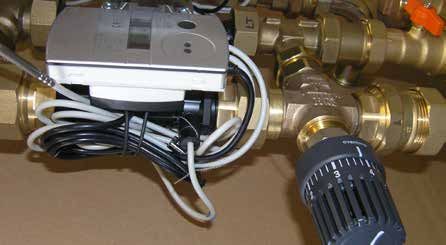
NOTES ON STRATIFIED STORAGE TECHNOLOGY
                                                                                                            ADVANTAGES AND BENEFITS

•     The patented, thermo-hydraulic layer system is based exclusively on physical principles/natural laws and
      does not require any control technology, neither electrical nor electronic nor mechanical, to function.
•     The operation of the shift system takes place without any (external) energy demand, only due to the
      natural law of gravity (hot water is lighter than cold water).
•     OSKAR has no wearing parts and is therefore fail-safe, maintenance-free and durable.
•     OSKAR stores heat (thermal energy) in the form of neutral, unproblematic heating water, which means
      that there is no risk of corrosion, calcification and germs, i.e. OSKAR has a practically unlimited service
      life.
•     Via the stratification system, not only heat flows from the most diverse heat generators are supplied in
      layers to the storage volume, but also all return flows from the heating circuits/heat consumers, which
      usually have very different temperatures.
•     The patented, thermohydraulic stratification and connection system ensures stable and fast-acting
      stratification of storage water of different temperatures.
•     Universal use, as it is not bound to any system and is basically compatible with all heat generators, heat
      consumption systems and associated control systems. Ideal combination of different heat generators,
      e.g. oil/gas boiler + solid fuel boiler/tiled stove + solar. When using OSKAR, complicated hydraulic
      and electrical/electronic circuits, pipe systems, as well as switching valves or other actuators/control
      valves are no longer necessary. The system design is simple, the control technology is minimised and
      operation is safer and more efficient.
•     Best possible utilisation of solar energy, e.g. almost 40 % total energy saving when using solar energy
      for heating and domestic hot water with only 10 m² collector area (result of a diploma thesis of the
      Munich University of Applied Sciences, Department of Supply Engineering, based on a single-family
      house in the Bavarian foothills of the Alps).
•     Maximum utilisation of condensation heat with condensing technology through a return temperature
      that is always cool; i.e. always the highest efficiency of the condensing heat generator.
•     Optimisation of burner running times and thus reduction of burner starts up to 70 % and pollutant
      emissions up to 50 %.
•     Lowest heat losses, even when connected, as all connections are located at the bottom, in the coolest
      storage tank area.
•     Hygienic drinking water heating (domestic hot water preparation) according to the continuous flow
      principle.

TU_D_Oskar°-10-2021-04-wi - Irrtümer und Änderungen aller Angaben, Bilder und Zeichnungen bleiben vorbehalten.
Die Einhaltung der allgemein gültigen und anerkannten Regeln der Technik und evtl. örtlicher Vorschriften sind unbedingt einzuhalten!
ACHTUNG! Installation, Verdrahtung nur durch autorisiertes Fachpersonal.                                                                5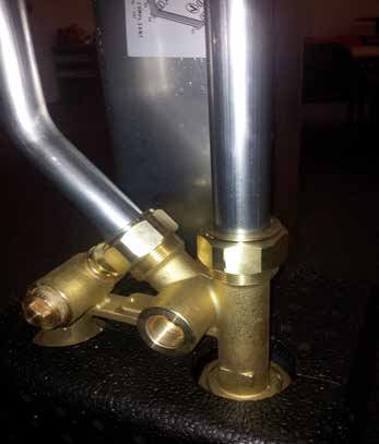
NOTES ON THE DOCUMENTATION
GENERAL NOTES

The following notes are a guide through the entire documentation.
Other documents are valid in conjunction with these operating and installation instructions.
The ratiotherm Oskar-10 must not be operated without these instructions.
The instructions must be made available to the operator and the specialist tradesman at all times for
information purposes. The instructions must be supplied with the Oskar-10 when it is sold.
The technical documentation can also be downloaded in PDF format from our homepage.
We accept no liability for damage caused by non-observance of these instructions.

TARGET GROUP:

                              These operating instructions are intended for
                              •   the operator (user) and
                              •   the specialist tradesman for the system.

STORAGE OF DOCUMENTS:

                              Keep these instructions and all applicable documents so that they are
                              available when needed.

                              Hand over the documents to the successor when moving out or selling.

SYMBOLS USED:

                                     Danger due to                       Warning against hot surfaces
        Danger zone                                                                                                                            STOP
                                    Electric current                                   and liquids

                                                                                                                             Mandatory signs for the wearing
  Switch off before working       Note before damage                      Read operating instructions
                                                                                                                               of pers. Protective equipment

                                                           TU_D_Oskar°-10-2021-04-wi - Irrtümer und Änderungen aller Angaben, Bilder und Zeichnungen bleiben vorbehalten.
                                          Die Einhaltung der allgemein gültigen und anerkannten Regeln der Technik und evtl. örtlicher Vorschriften sind unbedingt einzuhalten!
 6                                                                                                  ACHTUNG! Installation, Verdrahtung nur durch autorisiertes Fachpersonal.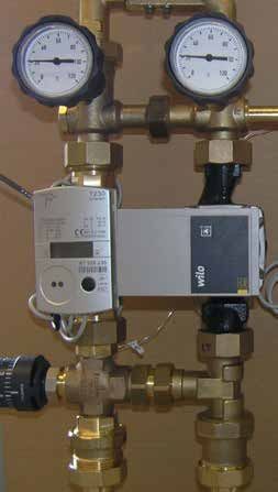
NOTES ON THE DOCUMENTATION
                                                                                                                                        INTENDED USE

The ratiotherm Oskar-10 is built according to the state of the art
and the recognised technical safety regulations.

In the event of improper use or use for other than the intended purpose, hazards to life and limb of the
user or third parties may arise.

                          Oskar-10 is not intended to be used by persons (including children) with reduced physical,
                          sensory or mental capabilities.

                          It is also not to be operated by persons with a lack of experience and/or knowledge.

                          •      unless they are supervised by a person responsible for their safety or have received
                                 instructions from that person on how to use the product.

                          The storage tank is intended exclusively for domestic and / or commercial use
                          for the preparation of hot water (domestic hot water) and for heat collection and distribu-
                          tion.

                          Any other use or use that goes beyond this is considered improper use. The manufacturer/
                          supplier is not liable for any damage resulting from this.

                          The risk is borne solely by the user (operator).

                          Intended use also includes observance of the operating and installation instructions as well
                          as all other applicable documents and compliance with the inspection and maintenance
                          conditions.

TU_D_Oskar°-10-2021-04-wi - Irrtümer und Änderungen aller Angaben, Bilder und Zeichnungen bleiben vorbehalten.
Die Einhaltung der allgemein gültigen und anerkannten Regeln der Technik und evtl. örtlicher Vorschriften sind unbedingt einzuhalten!
ACHTUNG! Installation, Verdrahtung nur durch autorisiertes Fachpersonal.                                                                          7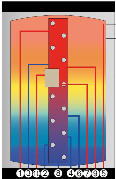
NOTES ON THE DOCUMENTATION
INTENDED USE

               The installation, commissioning or dismantling of the unit may only be carried out by
               a skilled person with specific knowledge required for the activities with this unit.

               The existing regulations, rules and guidelines as well as the local installation
               specifications must be observed.

CAUTION - DANGER OF SCALDING

               Safety valve and blow-out pipe
               The water volume increases during the heating process.
               Therefore, never close the blow-out pipe of the safety valve.

               Hot water can escape from the outlet pipe.
               Special care is required here with the solar station!

NOTE - CORROSION DAMAGE

               To avoid corrosion, do not use sprays, solvents, cleaning agents containing chlorine,
               paints, adhesives, etc. in the vicinity of the unit.
               of the unit.
               These substances can lead to corrosion under unfavourable circumstances.

WARNING - SPARE AND WEAR PARTS

               Components that have not been tested with the unit may cause damage to the unit
               or impair its functions.

               Only use original spare parts and original wear parts.

                                            TU_D_Oskar°-10-2021-04-wi - Irrtümer und Änderungen aller Angaben, Bilder und Zeichnungen bleiben vorbehalten.
                           Die Einhaltung der allgemein gültigen und anerkannten Regeln der Technik und evtl. örtlicher Vorschriften sind unbedingt einzuhalten!
 8                                                                                   ACHTUNG! Installation, Verdrahtung nur durch autorisiertes Fachpersonal.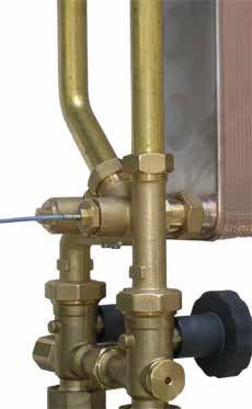
NOTES ON THE DOCUMENTATION
                                                                                GUIDELINES, STANDARDS AND LAWS

                                                     Bei der Aufstellung und Installation des Produktes sind insbesondere nachfolgende
                                                     Vorschriften, Regeln und Richtlinien zu beachten:

                                                     IN DEUTSCHLAND:

                                                     •       VDE- sowie EVU-Vorschriften und Bestimmungen (insbesondere VDE 0100);

                                                     •       Vorschriften und Bestimmungen der örtlichen Versorgungsunternehmen;

                                                     •       DVGW-Arbeitsblatt W 382
                                                             „Einbau und Betrieb von Druckminderern in Trinkwasserverbrauchsanlagen“;

                                                     •       DIN 1988 – TRWI Technische Regeln für Trinkwasserinstallation;

                                                     •       DIN 4753 – Wassererwärmungsanlagen für Trink- und Betriebswasser;

                                                     •       Unfallverhütungsvorschriften VGB 20 Unfallverhütungsvorschriften

                                                     •       Energieeinsparverordnung EnEV – Verordnung über energiesparenden
                                                             Wärmeschutz und energiesparende Anlagentechnik bei Gebäuden von 2009

                                                     Darüber hinaus können lokal weitere Vorschriften und Richtlinien z. B. örtliche
                                                     Bauordnungen zu beachten sein.

                                                     Grundsätzlich sind die im jeweiligen Land geltenden gesetzlichen Vorschriften
                                                     einzuhalten!

                                                     Nach DIN 1988 und EnEV § 10 müssen Kugelhähne in regelmäßigen Abständen
                                                     gewartet und inspiziert werden.
                                                     Bei extremer Beanspruchung ist die Überprüfung in kürzeren Zeitabständen
                                                     durchzuführen.
                                                     Kugelhähne sollten in 3 monatigen Abständen regelmäßig betätigt werden, um eine
                                                     leichtgängige Betätigung zu gewährleisten und eventuell entstehende Ablagerungen
                                                     auf der Kugel zu vermeiden und somit eine dauerhaft sichere Funktion zu sichern!

TU_D_Oskar°-10-2021-04-wi - Irrtümer und Änderungen aller Angaben, Bilder und Zeichnungen bleiben vorbehalten.
Die Einhaltung der allgemein gültigen und anerkannten Regeln der Technik und evtl. örtlicher Vorschriften sind unbedingt einzuhalten!
ACHTUNG! Installation, Verdrahtung nur durch autorisiertes Fachpersonal.                                                                9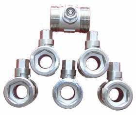
NOTES ON THE DOCUMENTATION
QUALIFICATION OF THE STAFF

             Dhe installation, commissioning or dismantling of the system may only be carried
             out by a specialist with specific knowledge required for the activities at this system.

             By personnel we mean all persons who work on the ratiotherm system.

             Trainees are not qualified personnel in this sense!

             •   We assume that

                 the operating personnel have been trained.

                 the maintenance personnel adjust, check and repair the ratiotherm system in
                 such a way that there is no danger to people or property.

                                          TU_D_Oskar°-10-2021-04-wi - Irrtümer und Änderungen aller Angaben, Bilder und Zeichnungen bleiben vorbehalten.
                         Die Einhaltung der allgemein gültigen und anerkannten Regeln der Technik und evtl. örtlicher Vorschriften sind unbedingt einzuhalten!
10                                                                                 ACHTUNG! Installation, Verdrahtung nur durch autorisiertes Fachpersonal.
NOTES ON SAFETY
UVV, INSTALLATION, CHANGES
To avoid injuries of any kind, the general accident prevention regulations must be observed
under all circumstances and personal protective equipment must be used accordingly.
Safe installation
• To ensure safe installation, the responsible installer must ensure that:
the personnel have the necessary qualifications
and receive the necessary training;
the personnel have read and understood the operating instructions;
the personnel have access to the operating instructions at all times;
the local accident prevention and environmental regulations are implemented and
complied with;
the personnel are instructed by the responsible supervisor and unauthorised persons
are kept away from the ratiotherm system;
TECHNICAL CHANGES
Safety devices must not be put out of operation.
Only original spare parts and original accessories from the manufacturer are to be used.
TU_D_Oskar°-10-2021-04-wi - Irrtümer und Änderungen aller Angaben, Bilder und Zeichnungen bleiben vorbehalten.
Die Einhaltung der allgemein gültigen und anerkannten Regeln der Technik und evtl. örtlicher Vorschriften sind unbedingt einzuhalten!
ACHTUNG! Installation, Verdrahtung nur durch autorisiertes Fachpersonal. 11TECHNICAL DATA
OSKAR-10/1,5/...
Type: Oskar°-10/1,5/... 750 1.000 1.300 2.000 3.000 4.000 Liter
actual volume approx: 720 920 1.340 2.010 3.000 4.000 l
Volume flow: 1.500 1.500 1.500 1.500 1.500 1.500 l/h
Total height without insulation: 1.730-1.770 2.110-2.150 1.990-2.030 2.100 1.940 2.440 mm
Total height with insulation: 1.890 2.270 2.150 2.220 2.080 2.560 mm
Diameter without insulation: 790 790 1.000 1.200 1.600 1.600 mm
Diameter with insulation: 990 990 1.200 1.440 1.840 1.840 mm
Length with connections front and rear 1.040 1.040 1.240 1.500 1.900 1.900 mm
Length with add-on manifold 1 1.387 1.387 1.587 1.847 2.247 2.247 mm
Length with add-on manifold 2 1.420 1.420 1.620 1.880 2.280 2.280 mm
Loading connections on the left/right side
Wide 1.015 1.015 1.220 1.470 1.870 1.870 mm
Length with add-on manifold 1 (347mm) 1.362 1.362 1.567 1.817 2.217 2.217 mm
Length with add-on manifold 2 (380mm) 1.395 1.395 1.600 1.850 2.250 2.250 mm
Weight without insulation approx: 140 155 220 285 470 550 kg
Tilting dimension max: 1.850 2.220 2.080 2.260 2.200 2.650 mm
Dimensional tolerances ± 10 ± 10 ± 10 ± 10 ± 10 ± 10 mm
Operating overpressure max: 3 3 3 3 3 3 bar
Operating temperature max: 95 95 95 95 95 95 °C
Pressure loss Oskar°: 20 20 20 20 20 20 mbar
Pressure loss Oskar°: 0,2 0,2 0,2 0,2 0,2 0,2 mWS
Standby heat loss DIN: 1,92 2,27 2,71 3,13 3,88 4,77 kWh/d
Air vent on top: ½“ ½“ ½“ ¾“ ¾“ ¾“ RIG
Material container: St 37-2 / S235JR / P265GH
Paintwork: black rust protection paint on the outside / raw on the inside
Position heights of the standard SE connections from the lower edge of the storage feet:
Nr. 1 Heat generator (HT) flow 1.598 1.911 1.767 1.920 1.727 2.106 mm
Nr. 2 Heat generator(LT) return 328 361 497 370 457 556 mm
Nr. 3 WHeat generator (LT) return 1.058 1.371 1.227 1.380 1.187 1.566 mm
Nr. 4 Consumer (LT) return 473 506 642 515 602 701 mm
Nr. 5 Consumer (HT) flow 1.668 2.016 1.387 2.025 1.798 2.211 mm
Nr. 6 Consumer (LT) return 738 771 907 780 867 966 mm
Nr. 7 Consumer (HT/LT) flow 1.313 1.626 1.482 1.635 1.442 1.821 mm
Nr. 8 Solar return 160 160 180 200 180 180 mm
Nr. 9 Solar flow 1.218 1.531 1.387 1.540 1.347 1.726 mm
Nr. 10 Heat generator (LT) flow 1.058 1.317 1.227 1.380 1.187 1.566 mm
Positioning of sensors S3 and S11 in the vertical immersion sleeve:
S3 Heating system HT / LT 500 500 500 500 500 600 mm
S11 Reference sensor solar + HG2 1.500 1.880 1.700 1.700 1.500 2.010 mm
TU_D_Oskar°-10-2021-04-wi - Irrtümer und Änderungen aller Angaben, Bilder und Zeichnungen bleiben vorbehalten.
Die Einhaltung der allgemein gültigen und anerkannten Regeln der Technik und evtl. örtlicher Vorschriften sind unbedingt einzuhalten!
12 ACHTUNG! Installation, Verdrahtung nur durch autorisiertes Fachpersonal.LOADING AND UNLOADING CONNECTIONS
Connections 1;2;3;10 = DN 25 RAG 1“
Loading connections standard Connections 4;5;6;7;8;9 = DN 25 flat sealing flange and union nut 1½“
3 2 1 10
125 mm 125 mm 125 mm
Oskar° 10/1,5
S1
S2
125 mm 125 mm 125 mm 125 mm 125 mm
4 5 6 7 8 9 S3
Loading connections LEFT
1
125 mm 125 mm 125 mm
2
10
3
125 mm 125 mm 125 mm 125 mm 125 mm
4 5 6 7 8 9
Loading connections RIGHT S11
2
125 mm 125 mm 125 mm
1
3
10
125 mm 125 mm 125 mm 125 mm 125 mm
4 5 6 7 8 9
TU_D_Oskar°-10-2021-04-wi - Irrtümer und Änderungen aller Angaben, Bilder und Zeichnungen bleiben vorbehalten.
Die Einhaltung der allgemein gültigen und anerkannten Regeln der Technik und evtl. örtlicher Vorschriften sind unbedingt einzuhalten!
ACHTUNG! Installation, Verdrahtung nur durch autorisiertes Fachpersonal. 13TECHNICAL DATA
OSKAR-WPS-10/1,5/...
Type: Oskar-WPS--10/1,5/... 750 1.000 1.300 2.000 3.000 4.000 Liter
actual volume approx: 720 920 1.340 2.010 3.000 4.000 l
Volume flow: 1.500 1.500 1.500 1.500 1.500 1.500 l/h
Total height without insulation: 1.730-1.770 2.110-2.150 1.990-2.030 2.100 1.940 2.440 mm
Total height with insulation: 1.890 2.270 2.150 2.220 2.080 2.560 mm
Diameter without insulation: 790 790 1.000 1.200 1.600 1.600 mm
Diameter with insulation: 990 990 1.200 1.440 1.840 1.840 mm
Length with connections front and rear 1.040 1.040 1.240 1.500 1.900 1.900 mm
Length with add-on manifold 1 1.387 1.387 1.587 1.847 2.247 2.247 mm
Length with add-on manifold 2 1.420 1.420 1.620 1.880 2.280 2.280 mm
Loading connections on the left/right side
Wide 1.015 1.015 1.220 1.470 1.870 1.870 mm
Length with add-on manifold 1 (347mm) 1.362 1.362 1.567 1.817 2.217 2.217 mm
Length with add-on manifold 2 (380mm) 1.395 1.395 1.600 1.850 2.250 2.250 mm
Weight without insulation approx: 140 155 220 285 470 550 kg
Tilting dimension max: 1.850 2.220 2.080 2.260 2.200 2.650 mm
Dimensional tolerances ± 10 ± 10 ± 10 ± 10 ± 10 ± 10 mm
Operating overpressure max: 3 3 3 3 3 3 bar
Operating temperature max: 95 95 95 95 95 95 °C
Pressure loss Oskar°: 20 20 20 20 20 20 mbar
Pressure loss Oskar°: 0,2 0,2 0,2 0,2 0,2 0,2 mWS
Standby heat loss DIN: 1,92 2,27 2,71 3,13 3,88 4,77 kWh/d
Air vent on top: ½“ ½“ ½“ ¾“ ¾“ ¾“ RIG
Material container: St 37-2 / S235JR / P265GH
Paintwork: black rust protection paint on the outside / raw on the inside
Position heights of the standard SE connections from the lower edge of the storage feet:
Nr. 1 Heat generator (HT) flow 1.598 1.911 1.767 1.920 1.727 2.106 mm
Nr. 2 Heat generator(LT) return 328 361 497 370 452 556 mm
Nr. 3 WHeat generator (LT) return 1.138 1.461 1.307 1.470 1.267 1.656 mm
Nr. 4 Consumer (LT) return 473 506 642 515 602 701 mm
Nr. 5 Consumer (HT) flow 1.668 2.016 1.837 2.025 1.798 2.211 mm
Nr. 6 Consumer (LT) return 738 771 907 780 867 966 mm
Nr. 7 Consumer (HT/LT) flow 1.138 1.461 1.307 1.470 1.267 1.646 mm
Nr. 8 Solar return 160 160 180 200 180 200 mm
Nr. 9 Solar flow 1.218 1.531 1.387 1.540 1.347 1.726 mm
Nr. 10 Heat generator (LT) flow 1.288 1.611 1.457 1.620 1.417 1.806 mm
Positioning of sensors S3 and S11 in the vertical immersion sleeve:
S3 Heating system HT / LT 800 800 800 800 800 900 mm
S11 Reference sensor solar + HG2 1.500 1.880 1.700 1.700 1.500 2.010 mm
TU_D_Oskar°-10-2021-04-wi - Irrtümer und Änderungen aller Angaben, Bilder und Zeichnungen bleiben vorbehalten.
Die Einhaltung der allgemein gültigen und anerkannten Regeln der Technik und evtl. örtlicher Vorschriften sind unbedingt einzuhalten!
14 ACHTUNG! Installation, Verdrahtung nur durch autorisiertes Fachpersonal.LOADING AND UNLOADING CONNECTIONS
Connections 1;2;3;10 = DN 25 RAG 1“
Loading connections standard Connections 4;5;6;7;8;9 = DN 25 flat sealing flange and union nut 1½“
3 2 1 10
125 mm 125 mm 125 mm
Oskar° 10/1,5
S1
S2
125 mm 125 mm 125 mm 125 mm 125 mm
4 5 6 7 8 9
S3
Loading connections LEFT
1
125 mm 125 mm 125 mm
2
10
3
125 mm 125 mm 125 mm 125 mm 125 mm
4 5 6 7 8 9
Loading connections RIGHT
S11
2
125 mm 125 mm 125 mm
1
3
10
125 mm 125 mm 125 mm 125 mm 125 mm
4 5 6 7 8 9
TU_D_Oskar°-10-2021-04-wi - Irrtümer und Änderungen aller Angaben, Bilder und Zeichnungen bleiben vorbehalten.
Die Einhaltung der allgemein gültigen und anerkannten Regeln der Technik und evtl. örtlicher Vorschriften sind unbedingt einzuhalten!
ACHTUNG! Installation, Verdrahtung nur durch autorisiertes Fachpersonal. 15TECHNICAL DATA
OSKAR-10/5,0/...
Type: Oskar°-10/5,0/... 2.000 3.000 4.000 Liter
actual volume approx: 2.010 3.000 4.000 l
Volume flow: 5.000 5.000 5.000 l/h
Total height without insulation: 2.100 1.940 2.440 mm
Total height with insulation: 2.220 2.080 2.560 mm
Diameter without insulation: 1.200 1.600 1.600 mm
Diameter with insulation: 1.440 1.840 1.840 mm
Length with connections front and rear 1.500 1.900 1.900 mm
Loading connections on the left/right side
Width with side connections incl. Iso. 1.470 1.870 1.870
Length with side connections incl. Iso. 1.470 1.870 1.870
Weight without insulation approx: 315 470 550 kg
Tilting dimension max: 2.260 2.200 2.650 mm
Dimensional tolerances ± 10 ± 10 ± 10 mm
Operating overpressure max: 3 3 3 bar
Operating temperature max: 95 95 95 °C
Pressure loss Oskar°: 45 45 45 mbar
Pressure loss Oskar°: 0,45 0,45 0,45 mWS
Standby heat loss DIN: 3,13 3,88 4,77 kWh/d
Air vent on top: ¾“ ¾“ ¾“ RIG
Material Behälter: St 37-2 / S235JR / P265GH
Paintwork: black rust protection paint on the outside / raw on the inside
Position heights of the standard SE connections from the lower edge of the storage feet:
Nr. 1 Heat generator (HT) flow 1.904 1.752 2.193 mm
Nr. 2 Heat generator(LT) return 474 377 673 mm
Nr. 3 WHeat generator (LT) return 1.224 1.057 1.503 mm
Nr. 4 Consumer (LT) return 534 537 843 mm
Nr. 5 Consumer (HT) flow 2.014 1.847 2.303 mm
Nr. 6 Consumer (LT) return 894 757 1.213 mm
Nr. 7 Consumer (HT/LT) flow 1.554 1.437 1.853 mm
Nr. 8 Solar return 200 180 200 mm
Nr. 9 Solar flow 1.554 1.497 1.853 mm
Nr. 10 Heat generator (LT) flow 1.324 1.162 1.603 mm
Positioning of sensors S3 and S11 in the vertical immersion sleeve:
S3 Heating system HT / LT 600 600 700 mm
S11 Reference sensor solar + HG2 1.700 1.500 2.010 mm
TU_D_Oskar°-10-2021-04-wi - Irrtümer und Änderungen aller Angaben, Bilder und Zeichnungen bleiben vorbehalten.
Die Einhaltung der allgemein gültigen und anerkannten Regeln der Technik und evtl. örtlicher Vorschriften sind unbedingt einzuhalten!
16 ACHTUNG! Installation, Verdrahtung nur durch autorisiertes Fachpersonal.LOADING AND UNLOADING CONNECTIONS
Connections 1;2;3;4;5;6;7;10 = DN 40 RAG 1½“
Loading connections standard Connections 8;9 = DN 25 RAG 1“
3 2 1 10
125 mm 125 mm 125 mm
OSKAR°
Oskar° 10/1,5
RL VL S1
S2
125 mm 125 mm 125 mm 125 mm 125 mm
4 5 6 7 8 9
S3
Loading connections LEFT
10
150 mm 150 mm
1
RL VL
2
150 mm
3
150 mm 150 mm 150 mm 150 mm 125 mm
4 5 6 7 8 9
Loading connections RIGHT
S11
1 10 3 2 8 4 6 9 7 5
3
150 mm 150 mm
2
RL VL
1
150 mm
10
150 mm 150 mm 150 mm 150 mm 125 mm
4 5 6 7 8 9
TU_D_Oskar°-10-2021-04-wi - Irrtümer und Änderungen aller Angaben, Bilder und Zeichnungen bleiben vorbehalten.
Die Einhaltung der allgemein gültigen und anerkannten Regeln der Technik und evtl. örtlicher Vorschriften sind unbedingt einzuhalten!
ACHTUNG! Installation, Verdrahtung nur durch autorisiertes Fachpersonal. 17TECHNICAL DATA
OSKAR-WPS-10/5,0/...
Type: Oskar-WPS-10/5,0/... 2.000 3.000 4.000 Liter
actual volume approx: 2.010 3.000 4.000 l
Volume flow: 5.000 5.000 5.000 l/h
Total height without insulation: 2.100 1.940 2.440 mm
Total height with insulation: 2.220 2.080 2.560 mm
Diameter without insulation: 1.200 1.600 1.600 mm
Diameter with insulation: 1.440 1.840 1.840 mm
Length with connections front and rear 1.500 1.900 1.900 mm
Loading connections on the left/right side
Width with side connections incl. Iso. 1.470 1.870 1.870
Length with side connections incl. Iso. 1.470 1.870 1.870
Weight without insulation approx: 315 470 550 kg
Tilting dimension max: 2.260 2.200 2.650 mm
Dimensional tolerances ± 10 ± 10 ± 10 mm
Operating overpressure max: 3 3 3 bar
Operating temperature max: 95 95 95 °C
Pressure loss Oskar°: 45 45 45 mbar
Pressure loss Oskar°: 0,45 0,45 0,45 mWS
Standby heat loss DIN: 3,13 3,88 4,77 kWh/d
Air vent on top: ¾“ ¾“ ¾“ RIG
Material Behälter: St 37-2 / S235JR / P265GH
Paintwork: black rust protection paint on the outside / raw on the inside
Position heights of the standard SE connections from the lower edge of the storage feet:
Nr. 1 Heat generator (HT) flow 1.904 1.752 2.192 mm
Nr. 2 Heat generator(LT) return 474 377 682 mm
Nr. 3 WHeat generator (LT) return 1.334 1.312 1.602 mm
Nr. 4 Consumer (LT) return 539 537 822 mm
Nr. 5 Consumer (HT) flow 2.014 1.807 2.262 mm
Nr. 6 Consumer (LT) return 794 757 1.212 mm
Nr. 7 Consumer (HT/LT) flow 1.244 1.252 1.542 mm
Nr. 8 Solar return 200 180 200 mm
Nr. 9 Solar flow 1.569 1.497 1.852 mm
Nr. 10 Heat generator (LT) flow 1.424 1.372 1.662 mm
Positioning of sensors S3 and S11 in the vertical immersion sleeve:
S3 Heating system HT / LT 500 500 600 mm
S11 Reference sensor solar + HG2 1.700 1.500 2.010 mm
TU_D_Oskar°-10-2021-04-wi - Irrtümer und Änderungen aller Angaben, Bilder und Zeichnungen bleiben vorbehalten.
Die Einhaltung der allgemein gültigen und anerkannten Regeln der Technik und evtl. örtlicher Vorschriften sind unbedingt einzuhalten!
18 ACHTUNG! Installation, Verdrahtung nur durch autorisiertes Fachpersonal.LOADING AND UNLOADING CONNECTIONS
Connections 1;2;3;4;5;6;7;10 = DN 40 RAG 1½“
Loading connections standard Connections 8;9 = DN 25 RAG 1“
3 2 1 10
125 mm 125 mm 125 mm
OSKAR°
Oskar° 10/1,5
S1
RL VL
S2
125 mm 125 mm 125 mm 125 mm 125 mm
4 5 6 7 8 9
Loading connections LEFT
S3
10
150 mm 150 mm
1
RL VL
2
150 mm
3
150 mm 150 mm 150 mm 150 mm 125 mm
4 5 6 7 8 9
Loading connections RIGHT
S11
1 10 3 2 8 4 6 9 7 5
3
150 mm 150 mm
2
RL VL
1
150 mm
10
150 mm 150 mm 150 mm 150 mm 125 mm
4 5 6 7 8 9
TU_D_Oskar°-10-2021-04-wi - Irrtümer und Änderungen aller Angaben, Bilder und Zeichnungen bleiben vorbehalten.
Die Einhaltung der allgemein gültigen und anerkannten Regeln der Technik und evtl. örtlicher Vorschriften sind unbedingt einzuhalten!
ACHTUNG! Installation, Verdrahtung nur durch autorisiertes Fachpersonal. 19STORAGE TANK INSULATION
2-PIECE 750/1000/1300
Lid insulation fleece Floor insulation fleece Cover plate with cut-out
Kabeldurchführung
Kabeldurchführung zum Aufklappen
Insulating jacket front Insulating jacket rear
Kleberosette
Profile covers
Front foot edge Foot edge back
Front foot panel Rear foot panel
TU_D_Oskar°-10-2021-04-wi - Irrtümer und Änderungen aller Angaben, Bilder und Zeichnungen bleiben vorbehalten.
Die Einhaltung der allgemein gültigen und anerkannten Regeln der Technik und evtl. örtlicher Vorschriften sind unbedingt einzuhalten!
20 ACHTUNG! Installation, Verdrahtung nur durch autorisiertes Fachpersonal.STORAGE TANK INSULATION
2-PIECE 750/1000/1300
Parts list thermal insulation Oskar° 750 litres Parts list thermal insulation Oskar° 1000 litres
Fleece insulation thickness 100mm Fleece insulation thickness 100 mm
2x PS panels basalt grey glossy with cover foil 2x PS panels basalt grey glossy with cover foil
1870 x 1560 mm 2240 x 1560 mm
1x PS lid basalt grey with cover foil 1x PS lid basalt grey with cover foil
Ø 992 x 30 mm Ø 796 x 30 mm
2x Fleece insulation cover 2x Fleece insulation cover
Ø 796 x 65 mm Ø 806 x 65 mm
1x Fleece insulation floor with 4 x breakout 1x Fleece insulation floor with 4 x breakout
Ø 796 x 65 mm Ø 806 x 65 mm
2x Profile cover with type plate 2x Profile cover with type plate
1846 x 250 mm 2216 x 250 mm
1x Front foot edge with velour band 1x Front foot edge with velour band
880 x 85 mm 880 x 85 mm
1x Rear foot edge with velour band 1x Rear foot edge with velour band
580 x 85 mm 580 x 85 mm
1x Front foot panel with mushroom band 1x Front foot panel with mushroom band
170 x 1516 mm 170 x 1516 mm
1x Rear foot panel with mushroom band 1x Rear foot panel with mushroom band
170x1516 mm 170 x 1516 mm
1x Adhesive rosette 1x Adhesive rosette
d 28 x Ø 110 mm d 28 x Ø 110 mm
1x Cardboard 1x Cardboard
2000 x 250 x 1650 mm 2380 x 290 x 1650 mm
Parts list thermal insulation Oskar° 1300 litres PROPERTIES:
Fleece insulation thickness 100mm The thermal insulation of the „PV“ storage tank insulation
consists of 100 or 120 mm in the jacket area, 120 mm in
2x PS panels basalt grey glossy with cover foil the cover area and 50 mm thick polyester fleece in the base
2105 x 1890 mm area.
1x PS lid basalt grey with cover foil
Ø 1204 x 30 mm The jacket insulation is designed as composite insulation
(polyester fleece with 1.3 mm thick polystyrene) and, de-
2x Fleece insulation cover pending on the storage tank size, in 2 to 4 segments.
Ø 1006 x 65 mm
1x Fleece insulation floor with 4 x breakout
The cover insulation made of 120 mm thick polyester fleece
Ø 1006 x 65 mm
has a polystyrene cover (disc) as the upper end.
2x Profile cover with type plate • Building material approval number Z-23.1.3-278
2081 x 250 mm Application temperature up to 160° C
good thermal properties up to WLG 0, 035 (035) DIN 52612
1x Front foot edge with velour band hygroscopically harmless, moisture-inactive
880 x 85 mm skin-friendly, allergy-friendly, breathable
resistant to vermin infestation, house dust mites
1x Rear foot edge with velour band
Stand-by heat loss according to DIN 4753-8
580 x 85 mm
at 45 K temperature difference 1.75 kWh/d
1x Front foot panel with mushroom band Fleece flame retardant, B1 according to DIN 4102 part 1
170 x 1845.6 mm Component flame retardant, B2 according to DIN 4102 Part 1
toxicologically harmless, textile tested for harmful substances
1x Rear foot panel with mushroom band according to Oeko-TexStandard 100 test no. 94.0.0541
170 x 1845.6 mm UV-stable and rot-proof
100 % unmixed, recyclable, flexible, keeps its shape
1x Adhesive rosette safe against mould DIN IEC 68, parts 2 - 10
d 28 x Ø 110mm Monitored by manufacturer
1x Cardboard
2200 x 310 x 2100 mm
TU_D_Oskar°-10-2021-04-wi - Irrtümer und Änderungen aller Angaben, Bilder und Zeichnungen bleiben vorbehalten.
Die Einhaltung der allgemein gültigen und anerkannten Regeln der Technik und evtl. örtlicher Vorschriften sind unbedingt einzuhalten!
ACHTUNG! Installation, Verdrahtung nur durch autorisiertes Fachpersonal. 21STORAGE TANK INSULATION
4-PIECE 2000/3000/4000
Profile covers
Insulating shell right
Foot rim right
Cover plate with cut-out
Insulating jacket rear
Rear foot panel
Foot edge back
Floor insulation fleece
Insulating jacket left
Left foot rim
Deckel-Isolier-Vlies
Isoliermantel vorne
Front foot panel
Front foot edge
Kleberosette
TU_D_Oskar°-10-2021-04-wi - Irrtümer und Änderungen aller Angaben, Bilder und Zeichnungen bleiben vorbehalten.
Die Einhaltung der allgemein gültigen und anerkannten Regeln der Technik und evtl. örtlicher Vorschriften sind unbedingt einzuhalten!
22 ACHTUNG! Installation, Verdrahtung nur durch autorisiertes Fachpersonal.STORAGE TANK INSULATION
4-PIECE 2000/3000/4000
Parts list thermal insulation Oskar° 2000 litres Parts list thermal insulation Oskar° 3000 litres
Fleece insulation thickness 120 mm Fleece insulation thickness 120 mm
4x PS panels basalt grey gloss with cover foil 4x PS panels basalt grey glossy with cover foil
2230 x 1133 mm 2050 x 1448 mm
1x PS lid basalt grey with cover foil 1x PS split lid, basalt grey with cover foil
Ø 1444 x 30 mm Ø 1844 x 30 mm (incl. 3 screws)
2x Fleece insulation cover Ø 1206 x 65 mm 2x Fleece insulation cover Ø 1606 x 65 mm
1x Fleece insulation floor with 4 x breakout 1x Fleece insulation floor with 4 x breakout
Ø 1206 x 65 mm Ø 1606 x 65 mm
1x Fleece strip 65 x 100 x 2850 mm 2x Fleece strip 65 x 100 x 2850 mm
1x Fleece stripes 65 x 100 x 880 mm 2x Non-woven fabrics 65 x 100 x 2100 mm
4x Profile cover 2 x with type plate 4x Profile cover 2 x with type plate
2206 x 250 mm 2026 x 250 mm
1x Front foot edge with velour tape 880 x 85 mm 1x Front foot edge with velour tape 880 x 85 mm
1x Rear foot edge with velour tape 580 x 85 mm 1x Rear foot edge with velour tape 580 x 85 mm
1x Front foot panel with mushroom band 170 x 1089.2 mm 1x Front foot panel with mushroom strip 180 x 1403.4 mm
1x Rear foot panel with mushroom strip 170 x 1089.2 mm 1x Rear foot panel with mushroom strip 180 x 1403.4 mm
2x Foot panel left + right 170 x 1089.2 mm 2x Left + right footboard 180 x 1403,4 mm
1x Adhesive rosette d 28 x Ø 110 mm 1x Adhesive rosette d 28 x Ø 110 mm
2x Cardboard 2350 x 300 x 1340 mm 2x Carton 2100 x 380 x 1340 mm
Parts list thermal insulation Oskar° 4000 litres PROPERTIES:
Fleece insulation thickness 120 mm The thermal insulation of the „PV“ storage tank insulation
4x PS panels basalt grey glossy with cover foil
consists of 100 or 120 mm in the jacket area, 120 mm in
2550 x 1448 mm the cover area and 50 mm thick polyester fleece in the base
area.
1x PS split lid, basalt grey with cover foil
Ø 1844 x 30 mm (incl. 3 screws) The jacket insulation is designed as composite insulation
2x Fleece insulation cover Ø 1606 x 65 mm (polyester fleece with 1.3 mm thick polystyrene) and, de-
pending on the storage tank size, in 2 to 4 segments.
1x Fleece insulation floor with 4 x cut-out Ø 1606 x 65 mm
2x Fleece strip 65 x 80 x 2850 mm
The cover insulation made of 120 mm thick polyester fleece
has a polystyrene cover (disc) as the upper end.
2x Fleece strip 65 x 80 x 2100 mm
• Building material approval number Z-23.1.3-278
4x Profile cover 2 x with type plate Application temperature up to 160° C
2026 x 250 mm good thermal properties up to WLG 0, 035 (035) DIN 52612
1x Front foot edge with velour tape 880 x 85 mm hygroscopically harmless, moisture-inactive
skin-friendly, allergy-friendly, breathable
1x Rear foot edge with velour tape 580 x 85 mm resistant to vermin infestation, house dust mites
Stand-by heat loss according to DIN 4753-8
1x Front foot panel with mushroom strip 180 x 1403.4 mm
at 45 K temperature difference 1.75 kWh/d
1x Rear foot panel with mushroom strip 180 x 1403.4 mm Fleece flame retardant, B1 according to DIN 4102 part 1
Component flame retardant, B2 according to DIN 4102 Part 1
2x Left + right footboard 180 x 1403,4 mm toxicologically harmless, textile tested for harmful substances
1x Adhesive rosette d 28 x Ø 110 mm according to Oeko-TexStandard 100 test no. 94.0.0541
UV-stable and rot-proof
2x Cardboard 2640 x 380 x 1620 mm 100 % unmixed, recyclable, flexible, keeps its shape
safe against mould DIN IEC 68, parts 2 - 10
Monitored by manufacturer
TU_D_Oskar°-10-2021-04-wi - Irrtümer und Änderungen aller Angaben, Bilder und Zeichnungen bleiben vorbehalten.
Die Einhaltung der allgemein gültigen und anerkannten Regeln der Technik und evtl. örtlicher Vorschriften sind unbedingt einzuhalten!
ACHTUNG! Installation, Verdrahtung nur durch autorisiertes Fachpersonal. 23STORAGE TANK INSULATION
ASSEMBLY
The insulation should be left in a warmer room for a longer period
of time before it is in a warmer room for a longer period of time
before installation to make it easier to fit.
Unpack the insulation and check for damage and completeness as
per the according to the enclosed parts list.
Align the storage tank with a spirit level.
The following insulation steps can also be carried out after installa-
tion.
However, it may be somewhat more difficult due to the pipework
and possibly narrow space conditions in the boiler room.
Insert the floor segments at the bottom.
Remove the foot rim panels from the insulation segment.
(Velcro fastener).
Set up the front and rear insulation segments.
Carefully guide the storage tank connections at the bottom
through the through the fleece openings.
At least 2 people are needed for this.
TU_D_Oskar°-10-2021-04-wi - Irrtümer und Änderungen aller Angaben, Bilder und Zeichnungen bleiben vorbehalten.
Die Einhaltung der allgemein gültigen und anerkannten Regeln der Technik und evtl. örtlicher Vorschriften sind unbedingt einzuhalten!
24 ACHTUNG! Installation, Verdrahtung nur durch autorisiertes Fachpersonal.STORAGE TANK INSULATION
ASSEMBLY
Connect the insulating segments by means of a toothed lock.
The insulating segments are secured by the spring and can no
longer come apart.
Insert additional fleece strips in the edge area of the storage tank.
Only for storage tank sizes 2000, 3000 and 4000 litres.
Insert both insulating fleece covers, paying attention to the ope-
ning for the Make sure that the immersion sleeve is in place.
Place the top cover with surrounding rubber profile on the insula-
tion.
For 3000 and 4000 litre storage tanks, the cover profile is divided
and connected with 3 screws.
TU_D_Oskar°-10-2021-04-wi - Irrtümer und Änderungen aller Angaben, Bilder und Zeichnungen bleiben vorbehalten.
Die Einhaltung der allgemein gültigen und anerkannten Regeln der Technik und evtl. örtlicher Vorschriften sind unbedingt einzuhalten!
ACHTUNG! Installation, Verdrahtung nur durch autorisiertes Fachpersonal. 25STORAGE TANK INSULATION
ASSEMBLY
The foot edges at the front and back with the decorative strips
by means of Velcro fasteners.
Protective film can now be removed
- at the latest when the installation work has been completed.
Stick on the rosette for the ventilation connection and attach the
Attach the profile cover to the two side strips.
Pre-insulated storage tanks.
TU_D_Oskar°-10-2021-04-wi - Irrtümer und Änderungen aller Angaben, Bilder und Zeichnungen bleiben vorbehalten.
Die Einhaltung der allgemein gültigen und anerkannten Regeln der Technik und evtl. örtlicher Vorschriften sind unbedingt einzuhalten!
26 ACHTUNG! Installation, Verdrahtung nur durch autorisiertes Fachpersonal.COMPONENTS
BALL VALVE SET (KS2)
Ball valve set (KS2) DN 25 / RAG 1½“
Procedure for re-sealing the ball valve using a stuffing box:
Ball valve Ball valve Inner nut
Open position Notch (I) Closed position Notch (-) Loosen with socket spanner
Retaining nut Adjusting head Stuffing box
remove pull off re-seal with open-end spanner
According to DIN 1988 and EnEV § 10, ball valves must be maintained and inspected at regular intervals.
In case of extreme stress, the inspection must be carried out at shorter intervals.
Ball valves should be operated regularly at 3-monthly intervals to ensure smooth operation and to avoid any
operation and to avoid possible deposits on the ball and thus to ensure a permanently safe
secure function in the long term!
TU_D_Oskar°-10-2021-04-wi - Irrtümer und Änderungen aller Angaben, Bilder und Zeichnungen bleiben vorbehalten.
Die Einhaltung der allgemein gültigen und anerkannten Regeln der Technik und evtl. örtlicher Vorschriften sind unbedingt einzuhalten!
ACHTUNG! Installation, Verdrahtung nur durch autorisiertes Fachpersonal. 27COMPONENTS
INSULATING CAPSULES - CUT TO LENGTH ON SITE
Längen für die Isolierung Kugelhanset
Oskar° 400l Oskar° 2000l/1,5
111
119
128
151
102
117
133
180
209
169
151
128
119
111
336
219
180
133
117
102
Oskar° 3000l/1,5
Oskar° 4000l/1,5
Oskar° 750l
Oskar° 1000l
111
124
106
119
132
167
186
155
142
124
111
266
195
167
132
119
106
Oskar° 1300l
101
111
122
150
224
172
150
111
122
101
Planbezeichnung: Name Datum
Achtung: Dieses Schema ist nur
Isolierstücke abschneid Gezeichnet W.Brandt 08.04.2014
eine Empfehlung und erhebt in
maße Geprüft A.Weiding. 08.04.2014 jeglicher hinsicht keinen
Anspruch auf Vollständigkeit
TU_D_Oskar°-10-2021-04-wi - Irrtümer und Änderungen aller Angaben, Bilder und Zeichnungen bleiben vorbehalten.
Die Einhaltung der allgemein gültigen und anerkannten Regeln der Technik und evtl. örtlicher Vorschriften sind unbedingt einzuhalten!
28 ACHTUNG! Installation, Verdrahtung nur durch autorisiertes Fachpersonal.COMPONENTS
BALL VALVE SET ON ADD-ON MANIFOLD 1 OR 2
Mount the ball valve set incl. enclosed Mount the support feet on the add-on Fit the add-on manifold to the ball valve set
seals on the storage tank. manifold Mount from the centre to the outside
Always mount the assemblies completely from left to right. It is particularly important with the TWK that the capillary
tube sensor is also mounted in front of the heating circuit, as otherwise you will not be able to reach it later.
Add-on distributor 1 Add-on distributor 2
for max. 3 assemblies for max. 4 assemblies
DHW station - Heating circuit - Solar station DHW station - Heating circuit LT + HT - Solar station
60 60
40 80 40 80
20 100 20 100
0 120 0 120 60 60
40 80 40 80
°C
°C °C
20 100 20 100
0 120 0 120
°C
°C °C
flow direction
flow direction
60 60
60 60 40 80 40 80
60 60 60 60 60 60
80 80 40 80 40 80 40 80 40 80 40 80 40 80
60 60 40 40
60 60 80 80
20 100 20 100
40 40
80 80 20 20 20 100 20 100 20 100 20 100
40 40 20 20 100 100
100 100
20 100 20 100 0 120 0 120
0 120 00 120 0 120 00 120
20 100 20 100 0 120 0 120 °C °C
0 120 0 120 °C °C
0 120 00 120 °C
°C °C
°C °C
°C °C
°C
°C
°C
°C °C
°C
0 120 0 120 °C
°C °C
°C
°C
I
I
OV
OV
5
III
III
II
II
II
I
OV
III
OV
4
III
5
II
I
II
3
OV
III
4
I
3
TU_D_Oskar°-10-2021-04-wi - Irrtümer und Änderungen aller Angaben, Bilder und Zeichnungen bleiben vorbehalten.
Die Einhaltung der allgemein gültigen und anerkannten Regeln der Technik und evtl. örtlicher Vorschriften sind unbedingt einzuhalten!
ACHTUNG! Installation, Verdrahtung nur durch autorisiertes Fachpersonal. 29COMPONENTS
ADD-ON DISTRIBUTOR TERMINAL ASSIGNMENT
Add-on distributor (ABV-1) for Oskar°-10/1.5/...
for mounting 3 assemblies
- TWK - HK1 (LT/HT) - SOK -
125mm Speicheranschlüsse Oskar°-10/1,5
6 x Überwurfmu�er R 1½“
4 5 6 7 8 9
125mm
TWK HK-NT oder HT SOK
4 5 6 7 8
4 x 1“ RAG 1 x ¾“ RIG
Add-on distributor (ABV-2) for Oskar°-10/1.5/...
for mounting 4 assemblies
- TWK - HK1 (LT) - HK2 (HT) - SOK -
125mm Speicheranschlüsse Oskar°-10/1,5
6 x Überwurfmu�er R 1½“
4 5 6 7 8 9
125mm
TWK HK-NT HK-HT SOK
4 5 6 7 4 x 1“ RAG 1 x ¾“ RIG 8
TU_D_Oskar°-10-2021-04-wi - Irrtümer und Änderungen aller Angaben, Bilder und Zeichnungen bleiben vorbehalten.
Die Einhaltung der allgemein gültigen und anerkannten Regeln der Technik und evtl. örtlicher Vorschriften sind unbedingt einzuhalten!
30 ACHTUNG! Installation, Verdrahtung nur durch autorisiertes Fachpersonal.COMPONENTS
MOUNTING REDUCTION SET / SPECIAL MOUNTING SET
Mounting reducer sets for assemblies TWK or heating circuit DN 25 and DN 32
ARS 2 ARS 3
DN 40 > DN 25 DN 40 > DN 32
65 mm 90 mm 65 mm 95 mm
180 mm
Special attachment set (ABSS2) for solar station assembly DN 40 > DN 25
Special mounting set with drainage Mounted on the memory connections 8 and 9
Components supplied loose for on-site installation
Insulating shells
TU_D_Oskar°-10-2021-04-wi - Irrtümer und Änderungen aller Angaben, Bilder und Zeichnungen bleiben vorbehalten.
Die Einhaltung der allgemein gültigen und anerkannten Regeln der Technik und evtl. örtlicher Vorschriften sind unbedingt einzuhalten!
ACHTUNG! Installation, Verdrahtung nur durch autorisiertes Fachpersonal. 31DRINKING WATER COMPACTION
HYDRAULIC CONNECTION
A
A = Turbine flow sensor
flow direction
Cold water connection
B = Hot water connection
C
C = Circulation connection
B
D = Forward
E = Return
(1) Assembly TWK auf ABV1 / ABV2 / ARS
Always mount assemblies completely from left
to right!
1160 mm
• (3) Mounting capillary tube sensor
(2) Assembly of actuator for heating water mixing for HW mixing valve (do not bend)
valve
• before installing the heating circuit!
Heating water mixing valve Setting values
1 2 3 4 5 6 7
40°C 45°C 50°C 55°C 60°C 65°C 70°C
50°C 55°C 60°C 65°C 70°C 75°C 80°C
You can read which settings apply from a label on the
capillary tube sensor
Advantages of premixing:
60 60
• Temperature pre-regulation
40 80 40 80
20 100 20 100
Reduction of energy consumption possible 0
°C
120 0
°C
120
Reduction of limescale
Active scald protection
Wilo
Tiefe:
280 mm
5
II
OV
III
4
I
3
125 mm
E D
TU_D_Oskar°-10-2021-04-wi - Irrtümer und Änderungen aller Angaben, Bilder und Zeichnungen bleiben vorbehalten.
Die Einhaltung der allgemein gültigen und anerkannten Regeln der Technik und evtl. örtlicher Vorschriften sind unbedingt einzuhalten!
32 ACHTUNG! Installation, Verdrahtung nur durch autorisiertes Fachpersonal.
                                            COMPACT
                                                 DRINKING WATER
                                                                   STATION
                                                                                                                                        ULTRA FAST SENSOR

                                                                                                                                        View from „behind


               Probe must be immersed in the medium!
               Measurement only takes place at the tip of the

               probe!


                                                         !!! Attention !!!
                                The lock nut for the O-ring seal of the sensing element must be
                                                                                                    ê
                      be professionally tightened so that the sensor cannot be pushed out by the internal
                           water pressure! Seal via the metal part of the sensor - not via the cable!
                                                                                                                           h
                                                                                                                                        II

TU_D_Oskar°-10-2021-04-wi - Irrtümer und Änderungen aller Angaben, Bilder und Zeichnungen bleiben vorbehalten.
Die Einhaltung der allgemein gültigen und anerkannten Regeln der Technik und evtl. örtlicher Vorschriften sind unbedingt einzuhalten!
ACHTUNG! Installation, Verdrahtung nur durch autorisiertes Fachpersonal.                                                                                                 33
COMPACT DRINKING WATER STATION
PLATE HEAT EXCHANGER
Plate heat exchanger - Cleaning - Water values
Due to the strong turbulence in the brazed plate heat exchanger, there is a high self-cleaning effect in the channels.
Nevertheless, in some applications the formation of deposits can be very high; this is the case, for example, with extremely
hard water and high temperatures.
We recommend installing a suitable softening system and checking the condition of the heat exchanger max. 1 year
after commissioning and setting a cleaning/maintenance cycle - earlier in the case of very high water hardness. Then it is
possible to clean the heat exchanger by circulating a cleaning liquid (CIP - Cleaning In Place). Carry out cleaning at regular
intervals.
Use a container with a weak acid, either 5% phosphoric acid or, if the heat
exchanger is cleaned more frequently, 5% oxalic acid. Pump the cleaning liquid
alternately through the heat exchanger.
For high-maintenance applications, we recommend on-site installed CIP
connections/valves to simplify maintenance. For best cleaning results, the
flow rate of the cleaning solution should be 1.5 times that in operation and
All acids and bases are dangerous preferably in backwash mode.
substances and should be used with After cleaning, do not forget to rinse the heat exchanger thoroughly with clear
great care! water. A solution of 1-2% sodium hydroxide (NaOH) or sodium bicarbonate
(NaHCO ) before the final rinse ensures that all 3 acids are neutralised.
Copper-brazed stainless steel plate heat exchanger - resistance recommendation
Electrical conductivity 10-500 µS/cm
pH value 7,5-9,0
Carbon dioxideCOMPACT DRINKING WATER STATION
DIMENSIONS, PERFORMANCE DATA TWK-S 70 / 90
1 1
1 Connection cold water ¾“ RAG
2 2
flow direction
2 Flow turbine
6 6
3 7
3 Connection hot water RIG 1“
5
4 Plate heat exchanger (PHE)
5 PHE manual ventilation (heating water side)
4
1160 6 Circulation connection ¾“ RAG
7 Insulation box WT unit
13
8 Connection heating water RL/VL 1½“ RAG
60 11 60
9a
40 80 40 80
20 100 20 100
9 Heating water mixing valve
0 120 0 120
°C
10 9a Capillary tube immersion sensor sleeve
12
10 Circulating pump BL 180 (PWM)
5
II
OV
III
4
I
3
9 8
125 230
11 Ball valve with thermometer
250 260
12 Gravity brake with manual setting
13 Hot water outlet sensor (drinking water side)
TWK-S 70 90 70 90 70 90 70 90
Heat-
80 108 98 131 70 93 78 105
Power (kW)
Heating water-
70 70 60 60
Inlet (°C)
Heating water-
24 23 14 13 21 20 15 14
Outlet (°C)
Cold water-
10 10 10 10
Inlet (°C)
Hot water-
60 40 50 40
Outlet (°C)
Hot water-
23 31 47 63 25 33 37 51
Capacity (l/min)
TU_D_Oskar°-10-2021-04-wi - Irrtümer und Änderungen aller Angaben, Bilder und Zeichnungen bleiben vorbehalten.
Die Einhaltung der allgemein gültigen und anerkannten Regeln der Technik und evtl. örtlicher Vorschriften sind unbedingt einzuhalten!
ACHTUNG! Installation, Verdrahtung nur durch autorisiertes Fachpersonal. 35COMPACT DRINKING WATER STATION
DIMENSIONS, PERFORMANCE DATA TWK-S 100
1 Connection cold water ¾“ RAG
1 1
2 2 2 Flow switch
flow direction
6
3
6
7
3 Connection hot water RIG 1“
5 4 Plate heat exchanger (PHE)
5 PHE manual ventilation (heating water side)
6 Zirkulationsanschluss ¾“ RAG
4
1160 7 Insulation box WT unit
8 Connection heating water RL/VL 1½“ RAG
13
40
60
80
11 40
60
80
20 100 20 100
0 120 0 120
°C
10
10 Circulating pump BL 180 (PWM)
11 Ball valve with thermometer
8
125 230 12 Gravity brake with manual setting
250 260
13 Hot water outlet sensor (drinking water side)
TWK-S 100 Performance data
Heat-
120 146 103 118
Power (kW)
Heating water-
70 70 60 60
Inlet (°C)
Heating water-
24 13 20 15
Outlet (°C)
Cold water-
10 10 10 10
Inlet (°C)
Hot water-
60 40 50 40
Outlet (°C)
Hot water-
35 70 37 57
Capacity (l/min)
TU_D_Oskar°-10-2021-04-wi - Irrtümer und Änderungen aller Angaben, Bilder und Zeichnungen bleiben vorbehalten.
Die Einhaltung der allgemein gültigen und anerkannten Regeln der Technik und evtl. örtlicher Vorschriften sind unbedingt einzuhalten!
36 ACHTUNG! Installation, Verdrahtung nur durch autorisiertes Fachpersonal.COMPACT DRINKING WATER STATION
CHARACTERISTICS TWK-S 70 / 90 / 100
Primary pumps:
70 kW 90 kW 100 kW
Sekundär (KW-Eintritt / WW-Austritt) Systemanschluss 1 und 3 Druckverlust-Brauchwarmwasser-Wärmetauscher Druckverlust-Brauchwarmwasser-Wärmetauscher
75 kW
Druckverlust-Sekundärseite (bar)
Druckverlust-Sekundärseite (bar)
70 kW
10 0 kW
90/ 90/100 kW
Druckverlust-Sekundärseite (l/min)
Druckverlust-Sekundärseite (l/min)
Example 70 kW station:
Primary charging temperature 60°C
Cold water inlet 10°C
Hot water outlet 49,5°C
Flow rate 25l/min
Diagram boundary conditions
Cold water inlet temperature 10°C
Volume flow primary 0,414 l/s
Attention!
maximal erreichbare Warmwassertemperatur (°C)
The values in the diagram are calculated. The actual values
may deviate due to the flow conditions in the heat exchan-
ger and possible contamination.
Reference values for flow rates
from standpipes
Shower fitting 9,6 l/min
Washbasin fitting 10,5 l/min
Bath mixer 15,0 l/min
TU_D_Oskar°-10-2021-04-wi - Irrtümer und Änderungen aller Angaben, Bilder und Zeichnungen bleiben vorbehalten.
Die Einhaltung der allgemein gültigen und anerkannten Regeln der Technik und evtl. örtlicher Vorschriften sind unbedingt einzuhalten!
ACHTUNG! Installation, Verdrahtung nur durch autorisiertes Fachpersonal. 37You can also read