Fabrication-aware Design for Furniture with Planar Pieces Wenzhong Yan , Dawei Zhao and Ankur Mehta
←
→
Page content transcription
If your browser does not render page correctly, please read the page content below
Robotica (2013) © Cambridge University Press 2013
                                         doi:10.1017/xxxx

                                         Fabrication-aware Design for Furniture with
                                         Planar Pieces
                                         Wenzhong Yan†∗, Dawei Zhao‡ and Ankur Mehta§
                                         †Mechanical and Aerospace Engineering Department, UCLA, Los Angeles, California
                                         ‡Computer Science Department, UCLA, Los Angeles, California
                                         §Electrical and Computer Engineering Department, UCLA, Los Angels, California
arXiv:2104.05052v1 [cs.GR] 11 Apr 2021

                                         (Accepted MONTH DAY, YEAR. First published online: MONTH DAY, YEAR)

                                         SUMMARY
                                         We propose a computational design tool to enable casual end-users to easily design,
                                         fabricate, and assemble flat-pack furniture with guaranteed manufacturability. Using
                                         our system, users select parameterized components from a library and constrain their
                                         dimensions. Then they abstractly specify connections among components to define the
                                         furniture. Once fabrication specifications (e.g. materials) designated, the mechanical
                                         implementation of the furniture is automatically handled by leveraging encoded domain
                                         expertise. Afterwards, the system outputs 3D models for visualization and mechanical
                                         drawings for fabrication. We demonstrate the validity of our approach by designing,
                                         fabricating, and assembling a variety of flat-pack (scaled) furniture on demand.

                                         KEYWORDS: Flat-pack furniture; Furniture design; Fabrication-aware design;
                                         Parameterized abstraction; Hierarchical composition.

                                         1. Introduction
                                         Three dimensional (3D) objects built from planar pieces have drawn extensive attention
                                         and been wildly applied to owe to their properties, including high strength-to-weight
                                         ratio,1 rapid design and prototyping,2 low cost,3 compact storage and transport.4
                                         Recently, digital fabrication techniques have greatly increased the ability of casual end-
                                         users to create certain physical objects by reducing necessary design and manufacturing
                                         investments. However, the creation of functional furniture is still limited to domain
                                         experts due to requirements of in-depth engineering understanding for design, skilled
                                         carpentry expertise for fabrication and assembly, and material resources to facilitate
                                         the whole process. To bring digital fabrication to this space, we have developed a
                                         computational design pipeline enabling casual end-users to easily handle the whole
                                         creation process of flat-pack furniture, from design, through fabrication, to assembly.
                                            In our system, the design process is abstracted and parameterized, which allows users
                                         to easily design their furniture models in a function-based manner without worrying
                                         about the low-level engineering implementation. Besides a conventional incremental
                                         method, we also harness a hierarchical composition scheme, which further facilitates and
                                         accelerates the design process by providing a recursive approach to construct complex
                                         models from relatively simple designs through combining functions. Moreover, an
                                         intersection auto-detection algorithm is employed to automatically identify connections
                                         that are not specified but necessary, and insert planar joints to finalize the designs.
                                         In other words, users merely need to specify a minimal number of connections that
                                         define the spatial structures of their furniture models; our system will automatically
                                         detect other necessary connections and insert specific joints accordingly to generate

                                         ∗
                                             Corresponding author. E-mail: wzyan24@g.ucla.edu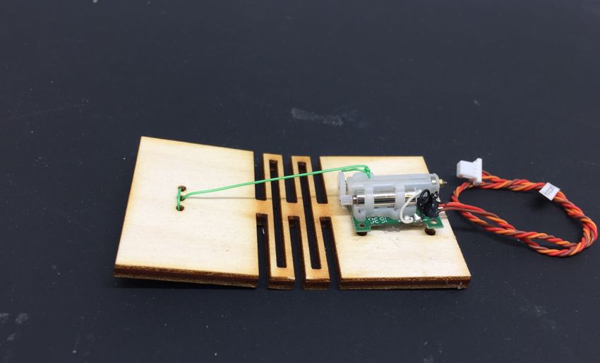
2 Fabrication-aware Design for Furniture with Planar Pieces
A B C D
2D fabrication file
§ Component selection 2D fab.
Picnic table § Dimension constraint
§ Connection definition
§ Fabrication specification Assembly
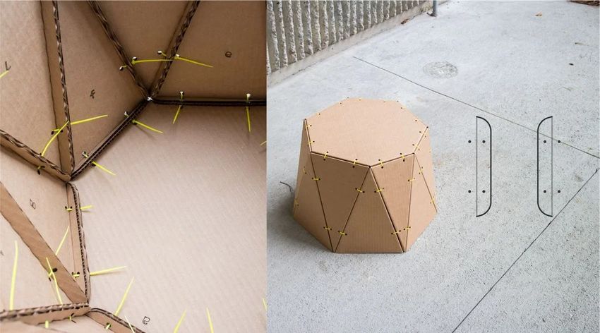
Fig. 1. Workflow for making furniture. We use a picnic table as an example. A) Conception of designs; B)
Design in our system. Users select components (or designs) from our library, constrains their dimensions,
define connections of selected components (or designs), and input fabrication specifications (e.g. materials
and corresponding thicknesses); C) 2D fabrication. The output 2D fabrication file is patterned on planar
materials (e.g. plywood, 3mm) by 2D fabrication machinery (e.g. laser cutter); D) Assembly. Furniture
are built with easy-to-assemble joints through interference fit.
fabricable embodiment of user-defined models. This algorithm releases users from the
tedious connection (and joint) specification process, increasing the flexibility of design
process by enabling users to freely build their furniture without being concerned with
the order of design. In addition, the incorporation of embedded planar joints within our
abstracted and parameterized design scheme greatly reduces the complexity of resulting
models and increases the feasibility of assembly for casual end-users. Combining all these
features, our system enables casual end-users to easily and intuitively design, fabricate,
and assemble flat-pack furniture with guaranteed manufacturability. Using our system,
users mainly need three steps to create their desired furniture. First, designers select
components (or use composed designs as components) from our library. Then they
abstractly define dimensions of selected components and specify necessary connections
between components to construct furniture models. Our system will automatically handle
the detailed fabrication-aware processing to output files for 3D visualization and 2D
fabrication. Finally, users assemble their furniture with ease thanks to the embedded
planar joint design. The creation process is simple and intuitive, allowing rapid and easy
design of sophisticated furniture for causal end-users. By adopting open-source software,
inexpensive raw materials and generalizable fabrication processes, our system expands
the accessibility of personalized design to a broader set of non-expert users.
In this paper, we present the following specific contributions:
r a computational design pipeline that allows casual end-users to easily generate
customizable, manufacturable, easy-to-assemble flat-pack furniture designs;
r an extensible framework that enables users to create furniture designs of arbitrary
complexity by hierarchically composing preexisted designs in a function-based manner;
r an algorithm that greatly increases the feasibility and flexibility of design process
through automatically detecting and inserting necessary joints (connections) for user-
defined furniture models; and
r a representative variety of (scaled) furniture designed and fabricated using the proposed
system.
2. Related work
This paper is inspired by the architecture of previous work,5, 6 which exclusively targets
at origami-inspired structures—3D geometries folded from stock sheets of negligible
thickness—to create a system which translated structural specifications into a fully
functional printable robots. Here, we focus on flat-pack furniture creation with thick
sheet materials, which brings in new challenges to design. We also draw upon other
academia in the broad categories of modeling by example, fabrication-aware design and
personal fabrication.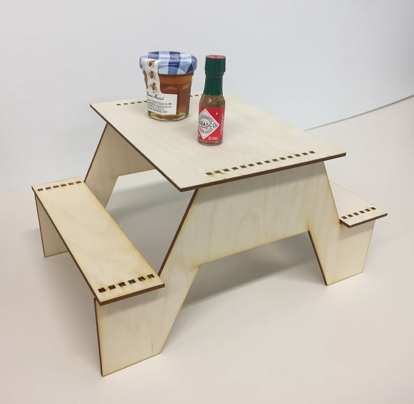
Fabrication-aware Design for Furniture with Planar Pieces                                3
2.1. Modeling by Example
Shape collections have been widely used to allow data-driven geometric modeling.7
Modeling by example8–10 enables the users to customize their own models by
manipulating existing templates from a large database built by domain experts. More
recent work uses recombination of model parts to expand the databases.11 Data-driven
suggestions can be used to provide recommendations for designs.12
   Perhaps the closest work to this project in terms of the desired goals comes from Schulz
et. al.,13 in which models—including furniture—could be physically realized via modeling
and fabricating by example. From an expert created database of fabricable templates
of finished designs, users could manipulate parameterized models with automatically
positioning, alignment, and composition. This “model by example” process thus allows
casual end users to explore a predefined design space bounded by example designs created
by domain experts. However, this “model by example” approach requires extensive efforts
from domain experts to build a representative library of the targeted models. In our work,
we propose a computational design pipeline for flat-pack furniture. Users are allowed to
freely design their desired models with their manufacturability guaranteed. Unlike “model
by example” method, no predesigned examples are needed to be created by domain
experts in our system; the resulting allowable design space can thus grow unbounded.

2.2. Fabrication-Aware Design
Manufacturability of resulting models has long been a concern in the computer graphics
community and attracted increasing interest recently.14 Fabrication-aware design is
proposed to guarantee generating fabricable models with fabrication specifications. It
is based on digital parameterization of the building models and then implemented by
considering the fabrication specifications through built-in algorithms. These systems
with fabrication-aware design aimed at empowering novice users without desired skills
to develop real world designs.
   Recently, an interactive system SketchChair15 was proposed to assist in designing
chair models that can easily be fabricated and assembled. This system automatically
generates a set of planar pieces that can be intersected along slots to form a 3D
realization of a designed chair model. Inspired by the same idea, Chen et. al.16 and
Hildebrand et. al.17 attempt to convert 3D structures into a set of simplified and
fabricable planar polygons connected by interlocking planar pieces. These ideas are
developed by building an interactive system where users can have access to real-time
feedback by incorporating structure optimization and analysis.18 Most of that work
employs a planar interlock mechanism to implicitly render the design due to its easy
manufacturability and assemblability. This interlock mechanism constrains the achievable
design space of furniture. Though this method can generate arbitrary solid geometries,
it requires dense interactions which may consume excess material.
   Our proposed systems makes use of an extensible collection of planar joints to connect
different planar elements to generate furniture designs. Similar to the interlocking slots,
these joints are rapidly fabricable due to their 2D geometries. A variety of furniture
designs have been enabled in this paper. In addition, the design space is potentially
extendable thanks to the abstract design scheme. Moreover, other planar joints can be
incorporated into our system to enable users to create more different types of furniture.

2.3. Personal Fabrication and Assembly
Based on the continued development of democratized tools,19–22 it is expected that casual
end-users will play an important role in designing and creating their own products in
the future. Several researchers have recently introduced systems for personal fabrication.
Spatial Sketch23 allows users to sketch in a 3D real-world space. This system realizes
the personal fabrication by converting the original 3D sketch into a set of planar slices
realized using a laser cutter and assembled into solid objects. Similarly, users can create
customized plush toys24 and chairs.15 These systems convert designs from 3D geometries
to a series of planar pieces to simplify fabrication. Post-processing assembly of varying
complexity is needed to complete the manufacture. Our work similarly approaches
4                                   Fabrication-aware Design for Furniture with Planar Pieces

          A                                 B                        C
                               Rec. 1            Rec. 1     Length

                                                                         Rec. 1

                                                 Width                                  Connected edge

                                                                                        Connected angle
                               Rec. 2
                 …                               Rec. 2    Length
                                                                                  90°   Rec. 2
               Library                           Width

Fig. 2. An illustration of a typical design process in our system. A) Users select two predefined rectangle
components from our library; B) Users specify the dimension of each component (e.g. widths and lengths
of the rectangles); C) Then they define the connection between the two rectangles at selected edges with
an 90 degree angle.

personal fabrication through the use of planar joints which are instinctively easy to
assemble, minimizing the need for careful positioning or hardware-based attachments.

3. System Overview
In this section, we will overview our system by outlining the design workflow and
discussing the design space enabled by our computational method.

3.1. Design Workflow
As shown in Fig. 1, our system assists inexpert end-users in handling the whole creation
process of flat-pack furniture, from design, through fabrication, to assembly. More
specifically, with a furniture model in mind, user can follow these 4 sequential steps
(Fig. 1B) to achieve their designs: 1) components selection; 2) parameter constraint;
3) connection definition; and 4) fabrication specification. To demonstrate the process,
we use a very simple model (two rectangles connected perpendicularly along an edge—
perhaps serving as a bookend—as shown in Fig. 2) as example. In the first step, casual
end-users select two pre-defined parameterized rectangle components from an existing
library (Fig. 2A) to match their conception of the designs (experts can create their
own components, see Section 4.1.1). Then, they constrain the selected components’
geometries, i.e. widths and lengths (Fig. 2B). In the third step, users construct the
design by defining the connections with connected edges and angle (Fig. 2C). In
the last step, given a description of available fabrication specifications (e.g. tools,
materials), our system will automatically produce manufacturable specifications that
capture dimensioned geometries, joint types and joint patterns into a 3D rendering file
and a 2D fabrication file. The 3D file can be used to visualize the design. The 2D file
can be directly sent to 2D fabrication machines (e.g. laser cutter); thus the resulting
fabricated components could be assembled into the desired physical models. Users can
repeat step 1-3 to construct designs of arbitrary complexity. In addition, hierarchical
composition (see Section4.2) could also be harnessed to create sophisticated furniture
models. It is worth noting that we represent all components as 2D polygons since they
are defined as planar geometries in our system and only substantialized as 3D structures
when fabrication specifications (especially material and its thickness) are resolved.

3.2. Design Space
Despite the arbitrary complexity of designs allowed in our system, the design space is
confined by the physical limitations of the joints. Currently, we employ three types of
joints, i.e. finger-finger joint, finger-hole joint and slot-slot joint (as shown in Fig. 6A,
B, and C), to implement corresponding connections. These joints are instinctively easy
to assemble, minimizing the need for careful positioning or hardware-based attachment
for casual end-users. However, more types of joints can be implemented to expand the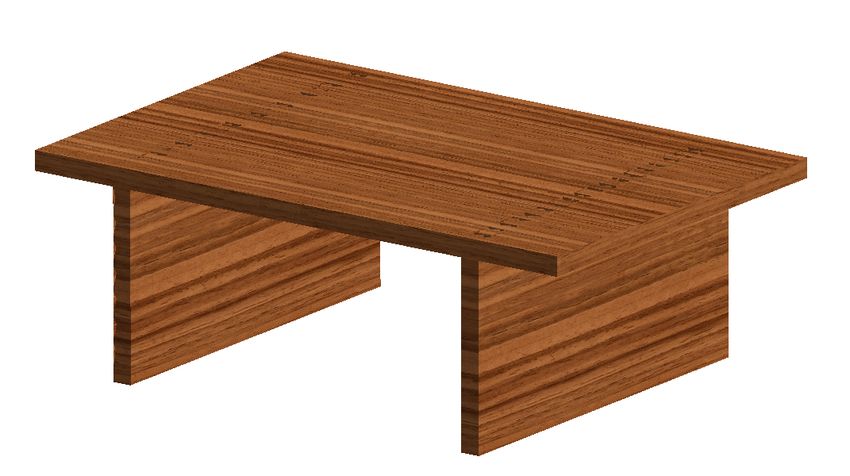
Fabrication-aware Design for Furniture with Planar Pieces                                5
design space to enable more functionalities of resulting models (e.g. active furniture), as
demonstrated in Fig. 6D-G.

4. System Implementation Workflow
In this section, we outline the 5 main steps of system implementation workflow, including
parameterized abstraction, hierarchical composition, coordinate placement, intersection
auto-detection, and output and assembly. 1) All design elements, including components,
connections, and resulting models, are parameterizedly abstracted, which allows users
to design furniture in a function-based manner; 2) A hierarchical composition algorithm
is then employed to enable users to create complex furniture by functionally combining
existing furniture models; 3) the 3D coordinates of all components are computed through
a coordinate placement algorithm; 4) these coordinates are then fed into an intersection
auto-detection algorithm to automatically identify necessary connections and thus place
joints to corresponding positions according to the input fabrication specifications to
finalize the models; 5) the resulting furniture models are output with 2D fabrication files
(such as .DXF and .SVG) and a 3D .STL file, ready for fabrication and assembly. In
addition, we describe the main operational features of our system in detail.

4.1. Parameterized Abstraction
The 3D geometries of flat-pack furniture in our system are defined as a composition of
components connected with some connections. In traditional furniture design process,
creating a piece of functional furniture design can be rather challenging since users
may need to adjust many parameters with complex dependencies while maintaining
the manufacturability and assemblability. Even with the aid of some CAD tools, users
may still experience great difficulties due to the lack of in-depth understanding of CAD
software and the manufacturing process.
   In order to allow casual end-users to design furniture with ease, our system largely
simplifies the design process into a abstracted function-based manner. To achieve this
abstracted design, we parameterize all elements in furniture creation process, including
components, connections, designated furniture models, and fabrication specifications.
Therefore, we introduce the parameterized abstraction of components, connections, and
furniture models in following paragraphs.
4.1.1. Components.
Representation: As mentioned before, components are represented as 2D polygons.
Therefore, in our system, a component’s fabrication-related parameters, e.g. material
type and its thickness, are not defined until specific fabrication and assembly methods
are determined by users in the final steps of the design process. At that time, these
abstract components are implemented automatically as 3D ingredients according to the
input fabrication specifications.
   Components in our system fall into two categories: basic components and hierarchically
composed components (later introduced in Section 4.2). Our system already comes with
a set of predefined, commonly-used polygon components, such as rectangle, trapezoid,
n-side polygon, etc. After abstract parameterization, every component in our system
is programmed as an object instantiated from a corresponding component class, and
represented as follows:

                   Component (para 1, para 2, ..., para i, ..., para n)

where Component is the component class name and para i is the ith predefined
parameter of the component. To instantiate a component object of the corresponding
component class, users only need to specify the parameters.
Construction: Fig. 3 uses a rectangle component as an example to demonstrate how
we construct a component class in our system (each component is an instance of the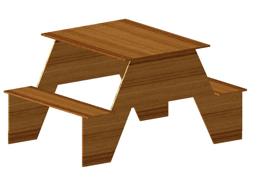
6                                      Fabrication-aware Design for Furniture with Planar Pieces
                A   y
                                                       B
                 (0,w)             l           (l,w)
                                  t

                    w    l                 r

                                  b                x
                 (0,0)                         (l,0)

Fig. 3. An example of parameterized abstraction. A) Rectangle component geometric diagram with
parameters labeled; B) Program implementation of a parameterized rectangle class in Python script in
our system.

component class). Firstly, users need to define the parameters of the component class
(line 2-3), which are the length l and width w of the rectangle in this case. Then, users
will specify the outer vertices of the component class whose order follows the right-hand
rule so that the front of the component is facing the out-of-page direction (line 5). Lastly,
users set a series of interfaces to the component class, which are some ports that can
be used to connect with the interface of other components. In this example, we set the
edges of the rectangle as interfaces with name b, r, t, and l. Thus, we have a rectangle
class with 4 interfaces and two parameters. This mechanism applies to other component
classes.
   Users can also define their own custom components following the same workflow
illustrated above, which only requires them to specify the parameters, vertices, and
interfaces of the components. Customizing components is one way to define desired
components when they are not available in our library. Also, users can harness
hierarchical composition (see Section 4.2) to piece together elementary components into
new complex component. For example, we can obtain a “L” shape new component
by combining two rectangles together along edges. It is worth noting that users are
allowed to define components with fewer parameters, called meta-parameters, by adding
some geometric constraints to the original parameters. Thus, users won’t be exposed to
enormous design parameters when design becomes complicated. For example, we can only
select the length of the rectangle as the manipulable meta-parameters and geometrically
constrain its width as a half of its length to create a component with a fixed aspect ratio.
4.1.2. Connection.
Representation and Construction: Connections in our system are also
parameterizedly abstracted. Once a connection has been defined, we build an associated
connectivity item to store all its information that is efficient to embody the connection
physically in following operations. A connection is represented by a directed line in a
connectivity graph of a furniture model. Here we use a computer, as shown in Fig. 4 as
example. In the figure, connection 1 ( 2 →− 1 ) denotes that component 2 is connected
to component 1 at some interfaces. In the graph, the edges of the line represent the
connected interfaces of corresponding components. The direction specifies the way we
construct the connection. Note that 1 ( 1 →   − 2 ) is different from 1 ( 2 → − 1 ). More
explanations would be found in the following paragraph.
  Finding a proper way to specify the abstracted connection between two components
can be non-trivial because it needs to be accurate, concise, and intuitive for users, while
being able to express all possible spatial relations. In our system, the connection is
constructed abstractly as a 5-tuple. For instance, when component CA is connected to
CB , we can call the constructor to define the connection:

                             Connection( (CA , IAi ), (CB , IBj ), PA , PO , PR )

where CA and CB are two connected components. In this expression, the first component
CA is connected to the second component CB . In this connection, CA is named as
the connecting component and CB is named as the connected component. Thus, this
connection could be shortly annotated as Connection(A →
                                                      − B). The sequence of the two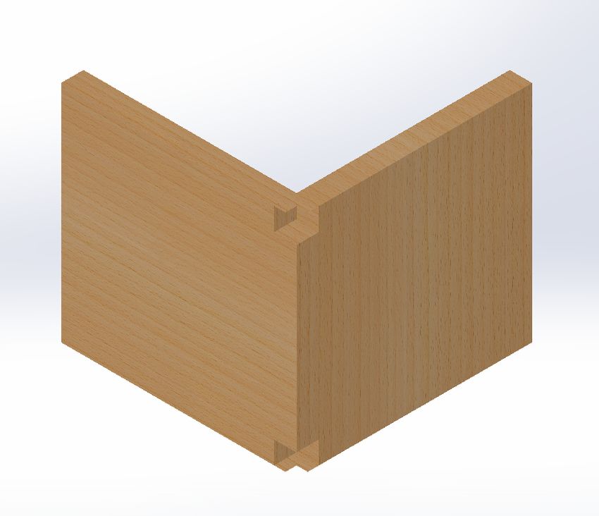
Fabrication-aware Design for Furniture with Planar Pieces                                              7
                   A                                       B
                                               3               1               2
                   1                                   2               1
                                   2

                                                                           3       2
                       1                   4       3               4                       3
                                               5       4
                                       5
                                                                       5               4
                                                                               5

Fig. 4. Representation of a furniture model. We take a computer desk as an example. Components
labelled as circled number, e.g. 1 ) and connections as boxed number, e.g. 1 . A) 3D model of the desk;
B) Connectivity graph of the desk with connections represented as directed yellow lines, whose directions
indicate the connection orientation.)

components matters. IAi and IBj represent the selected interface i of component CA and
the interface j of component CB . These two selected interfaces will be connected together.
PA , PO , PR represent the alignment, offset, and rotation of the connection. The value
of PA is either “front-front” or “front-back”. “Front-front” means that two connected
components have the same orientation while “front-back” indicates their orientation is
opposite to each other. PO is a 3-tuple, specifying the 3D offset vector that component A
(connecting component) should travel in accordance with. PR is also a 3-tuple, defining
how component A along with its local coordinate system is rotated around its own x, y,
and z axis, respectively. For example, in Fig. 4B, the connection between component 1
and 2 can also be described as Connection( 2 →     − 1 ).
   Using this 5-argument connection constructor, we can represent any possible spatial
relations between two components while providing users an intuitive and easy way to
state connections. Here we will illustrate this connection constructor in detail (see Fig.
5). For instance, Connection( (A, t), (B, b), f ront − f ront, (vx , vy , vz ), (θx , θy , θz )) can
be visualized as in Fig. 5B. From the connection constructor, we know that interface t of
component A is connected to interface b of component B. Since the alignment is specified
as “front-front”, the orientation of both faces facing up results in a temporary position
as the left graph in Fig.5B. x-y-z is the coordinate of component B being set as the
global coordinate for this connection while x’-y’-z’ is the local coordinate of component
A, fully overlapping with B’s. Then a 3D offset vector (vx , vy , vz ) is applied to component
A (as the middle graph shows) and followed by a 3-Axis rotation (θx , θy , θz )) to change
the orientation of the component (e.g. (90,0,0) represents a 90◦ rotation about x axis
as in the right graph in Fig. 5B). The other case with “front-back” alignment is also
presented in Fig. 5C. Though rather simple and intuitive, the connection specification
process could be greatly simplified with a graphic user interface later on.

Physical Implementation: Though parameterized abstraction can greatly facilitate
the design process, the connections need to be implemented physically to actually join
connected components when it comes to manufacture. In this paper we decide to use
planar joints to embody the connections to reduce the difficulty of fabrication and
assembly. Thus, users do not need to go through the tedious assembly process with
system-defined joints.13
   To enable the manufacturability of furniture designs, joints must be added at places
of intersections. However, for casual end-users, determining and drawing proper joints
patterns can be a liability, even with the help of some design software like AutoCAD or
Inkscape. Our computational design tool will automatically add one of the three types
of joints (as shown in Fig. 6A, B, and C, respectively) according to specific abstract
connections. More details for these three types of joints can be found in Appendix A.1).
The joints that we introduce here have the following two advantages: 1) they can be
easily fabricated using modern 2D manufacturing tools (e.g. laser cutter, waterjet, and
jigsaw); 2) are handy to assemble even without skilled craftsmanship.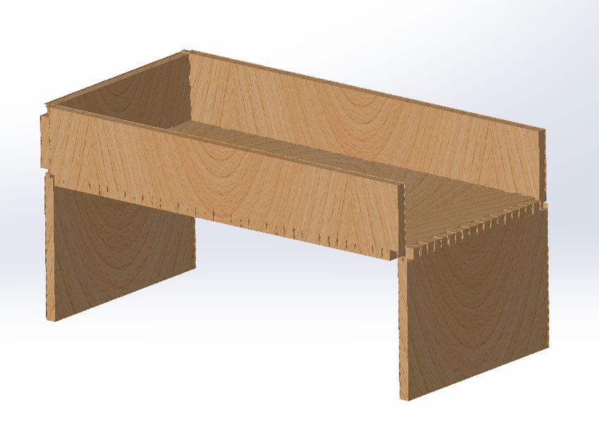
8 Fabrication-aware Design for Furniture with Planar Pieces
z z z
A B z(z')
z'
y y(y') y y
l l l
t b t b t y' z'
b
r r r
x x(x') x x
x' x'
y'
Component A
Alignment, PA Offset, Po Rotation, Pr
z C z(z') z z
z'
y y(y') y y
r
l b t l y'
t b t z'
b l
r r
x x x
x(x')
x' x'
Component B y'
Fig. 5. Connection visualization. A) Component A and B with their interfaces labelled and original
coordinates specified; Connections with “front-front” alignment B) and “front-back” alignment C). Left:
Alignment defined; Middle: 3D offset; Right: 3-axis rotation.
Theoretically, any joints, especially those that satisfy the above requirements, can be
incorporated into our system since the joints are merely the physical implementation of
abstracted connections.25 For example, the flap joints26 (see Fig.6D, not implemented
in our system) could potentially be adopted to achieve edge-edge connections. Further
work could be done to extend our library of joints to expand the design space.
In addition, active joints could be possible to realize connection implementation, which
leads to active devices, such as active furniture and robots. As a proof of concept, we
create cable-driven joints to allow resulting devices to have angular movements. For
example, we connect two rectangle components with a cable-driven joint, as shown
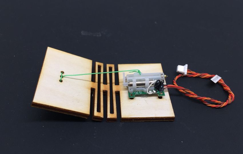
in Fig.6F and G. The fabrication pattern is shown in Fig.6E. By adding a lattice
pattern27 (more details can be found in Section A.2) along the connected edges of the two
rectangles, a flexible joint is formed to allow angular movements between two connected
components. A linear motor with its shaft is tied to the left rectangle using a cable, is
then attached on the right rectangle, as shown in Fig.6F. The back-and-forth movement
of the shaft of the motor will change the angle between two components (see Fig.6F and
G). Presumably, this type of joints can be used as living hinges for doors of furniture or
movable joints of robots.
In this paper, joints are mainly assembled through interference fit, which means
optimal interference amplitudes are needed to be calculated based on the fabrication
specifications. Our system can automatically output the optimal profiles of joints once
the fabrication specifications (e.g. materials and fabrication machines) are defined by
users. More details could be found in Appendix A.1.
4.1.3. Model.
Using the connection constructor specified on relevant components, an abstract design
model is built internally to store all the information (including components with specific
geometry constraints and connections between components) relevant to the design. This
designed model can be visualized as a directed connectivity graph. Here, we use a
computer desk as an example. As shown in Fig. 4A, the computer desk consists of five
rectangle components and five connections. The connectivity graph of the computer desk
is shown in Fig. 4B. Each component is labeled as a circled number, such as 1 and each
connection is represented by a numbered symbol, e.g. 1 . Each directed edge denotes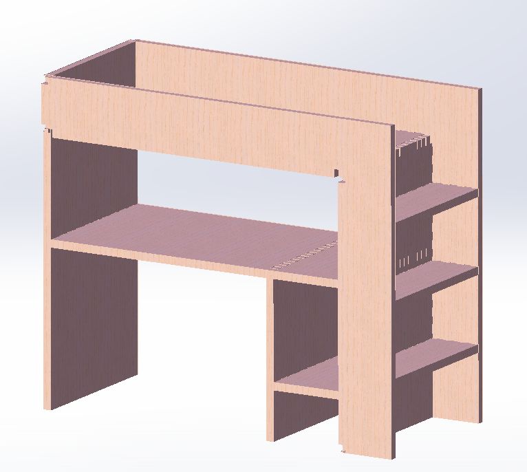
Fabrication-aware Design for Furniture with Planar Pieces                                               9
   A                         B                         C                       D

       Joint                     Joint                     Joint                   Joint

   E                                     F                             G

Fig. 6. Joint collection. A) A finger-finger joint for an edge-edge connection; B) A finger-hole joint for
an edge-face connection; C) A slot-slot joint for a face-face connection; D) A flap joint for edge-edge
connection.26 E The fabrication pattern of a cable-driven joint. The relax and bent states of the joint
are shown in F and G, respectively. It is worth noting that cables are needed for both flap joints and
cable-driven joints and linear motors are required for cable-driven joints.

a connection with its vertices intersected with circles at their corresponding interfaces.
For example, component 1 is connected to one interface of component 2 resulting in
connection 1 while component 3 is connected to another interface of component 2
to form connection 2 . Thus, a connectivity graph effectively includes all information
relevant to the corresponding design. By traversing the graph following the algorithm
presented in Section 4.3, we can generate the 3D coordinates of each component of the
design for further operations. Each connectivity graph, representing a design, can also
be stored in our library as a .YAML file, which can be in turn used as a new component
to hierarchically compose more complex designs in a function-based manner.

4.2. Hierarchical Composition
4.2.1. Design Principle.
To enable users to build complex furniture designs with ease, we harness function-
based hierarchical composition, which allows users to recursively build up to the desired
complex furniture constructions from relatively simple existing designs. This means we
organize all the parameterized data of the furniture design into a hierarchical tree, whose
structure is defined by how we recursively create the furniture. In this manner, functional
models at any level could be treated as components to construct higher level furniture
designs. For instance, to build a bunk bed as illustrated in Fig. 7D, instead of building
the whole piece from scratch, user can simply select these existing designs, a computer
desk, a bed, and a ladder (as shown in Fig. 4.2A, B, and C, respectively) to be composed
together. The computer desk, bed, and ladder can be further decomposed into elementary
components (e.g. rectangle). Therefore, the ith level hierarchy M i of a hierarchically
composed model can be written as:

               M i = ({Componenti }, {Connectioni }, {Constrainti }, {Interf acei })

where {Componenti } is a set of “basic” components consisting of the hierarchical design
in this level. Each “basic” components in this set can be a composed furniture design
or an elementary component. {Connectioni } is a set of connections specifying how the
“basic” components are connected, {Constrainti } is the set of parameters constraining
model M i , and {Interf acei } is the set of interfaces of the new hierarchically composed
model M i .
10                                                       Fabrication-aware Design for Furniture with Planar Pieces

     A                                           B                                       C                           D              Bed
                         2                                                                           2
                                                                     5
                                                             4                               1               5
                                                                             2                       3
         1                       4           3       1
                                     5                                           3
                                                                                                     4                       Desk

                                                                                                                                          Ladder
     E 1                     2                   F               5                       G           2
                                                                                                                     H
                 1                                       6                                   1               4                      3
                                                                     4
                     3           2                           1           2                       2       5
             4                               3       1           2                   3   1           3           5       1

                                                                     3                       3               6
                 5                       4               5                                                                          2
                             5                                   4                                   4

Fig. 7. A illustration of hierarchical composition with a bunk bed. Three “components”, i.e. a computer
desk A), a bed B), and a ladder C) are composed into a bunk bed D). Each “component” itself is
a furniture design with certain functionalities. The connectivity graphs of three “components” are also
pictured in E), F), and G). The final connectivity graph of the bunk bed is also directly composed of
all “components” H).

4.2.2. Model Reconstruction.
Each design in our system is represented and stored as an abstract connectivity graph.
When users compose several simpler designs into a more complex functional model, all
connectivity graphs will be added to an new high-level connectivity graph as per the
connections specified at this hierarchy by the user. This means that all information of
each simpler design is integrated to construct a new hierarchical data tree with its own
components and connections preserved, as shown in Fig. 7E-H. In the same manner, this
hierarchical data tree will be integrated as a branch of a new tree at a higher hierarchy
when current design is composed into a more complicated furniture.

4.3. Coordinate Placement
To place each component in a global coordinate system and find the places of intersections
to add proper joints, we employ a coordinate placement algorithm. At the design stage,
we require users to define connections between components. However, these connections
only specify the relative spatial relation, which is not necessarily the positions at which
joints are placed. Therefore, we use an intersection auto-detection algorithm (see Section
4.4) to place necessary joints based on the derived spatial relation to finalize the design
for manufacturing and assembly. Having derived the connectivity graph representing the
furniture designs, our system can perform a traversal on the graph to recursively compute
the 3D coordinates of each component following Algorithm 1, which will later be used
to build up the 3D model.
   Initially, each component is placed within its own local coordinates as defined by
the user as in Fig. 3A. Our goal is to find each component’s 4 by 4 transformation
matrix, Tglobal , which transforms the homogeneous coordinates of the original components
into a global 3D coordinates space as per the connections. To do so, we adopt the
recursive Algorithm 1. The input of the function consists of the component set C, a
4 by 4 transformation matrix Tglobal that represent its global coordinate. The algorithm
randomly selects a component Ci as a starting point and recursively find the coordinate
of all components connected to it. This step starts by storing the transformation matrix
as an attribute of the component. Then, for each connection, e.g. Connection(A →      − B),
that involves this component, if this component Ci is connected to component C B (i.e.
Ci = CB , line 5), we can find the relative transformation, Trelative , through the function,
F indRT (Connection(A →     − B)), between them and times the global transformation
                                                                                 0
matrix of CB (= Ci ) to obtain the new global transformation matrix Tglobal to run
the next iteration until the 3D coordinates of all components are calculated (line 6-8).
Another execution will be made for CA . If Ci is connecting component C A (i.e. Ci = CA ,
Fabrication-aware Design for Furniture with Planar Pieces 11
Algorithm 1 Compute the global 3D coordinates for every component of the component
set {C} of a design based on the defined associated connections
1: Randomly select a component Ci from {C}
//Return coordinates of components connected to Ci
2: function Find3D(Ci , Tglobal )
3: Ci .T3D ← Tglobal
4: for Connection(A → − B) in Ci .Connections do
//Ci is connected component
5: if Ci is CB then
6: Trelative ← F indRT (CA←B ) . Find relative transformation matrix
0
7: Tglobal ← Tglobal · Trelative . Calculate new global transformation matrix
0
8: return Find3D(CA , Tglobal )
//Ci is connecting component
9: else if Ci is CA then
10: Trelative ← F indRT (CA←B ) . Find relative transformation matrix
0 −1
11: Tglobal ← Tglobal · Trelative . Calculate new global transformation matrix
0
12: return Find3D(CB , Tglobal )
A 4 7 9 10 8
B C
5 5 10 5 11
9 10
6 (16) 10 11
7 (17) (14) 7 8
(13) (15)
(14) (15)
4 8 9 8 9
6
3 (11) 2 (16) (17) 5
(12) 4
1 2 6 (13)
4 7 6
1
3 3 (11) (12)
1 2 2
1 3
Fig. 8. An illustration of intersection auto-detection. Components labelled as circled number, e.g. 1 )
and connections as boxed number, e.g. 1 . A) 3D model of a reading desk; B) Connectivity graph; C)
Fabricated and assembled (scaled) reading desk with 3mm plywood. Note: this desk can also be built
through hierarchical composition, which will be discussed later in Section 5.2.
line 9), then we should find the inverse of the relative transformation between them and
times the global transformation matrix of CA (= Ci ) to have new global transformation
0
matrix Tglobal to run the next iteration (line 10-12).
4.4. Intersection Auto-Detection
After the coordinate placement phase illustrated in Section 4.3, we derive the global 3D
coordinates for all components, but the design is still by no means manufacturable.
In other words, we need to detect the places of intersections and add proper joint
mechanisms to finalize the model as well as to ensure its manufacturability. By performing
an automatic intersection detection, we release users from the burden of specifying all
places of intersections with connections explicitly. More specifically, using the connection
constructor, user can easily build the 3D model for their designs with a minimal number
of connections, which may not include all necessary intersections. Then our algorithm can
automatically handle the intersection detection to guarantee the manufacturability and
functionality. This algorithm is particularly useful for hierarchical composition because
it is very challenging for causal end-users to specify all necessary connections thoroughly
due to the geometry complexity. Hence, it help users to focus on design in a function-
based manner.
In this section, we use a reading desk, as shown in Fig. 8A, as an example to illustrate
the algorithm. To design such a reading desk with 11 components and 17 joints, user12 Fabrication-aware Design for Furniture with Planar Pieces
Algorithm 2 Find all necessary intersections and joints of a designed model composed
of a set of components {C} and specified connections
1: function IntersectionDetection({C})
//Merge coplanar faces
2: for Ci in {C} do
3: for Cj in {C} do
4: if coplanar(Ci , Cj ) ∧ Ci ∩ Cj 6= ∅ then
5: Vi∪j ← (Ci ∪ Cj ) . find the geometric union of Ci , Cj
−1
6: Ci .V 2D ← Ci .T 3D · Vi∪j . convert to global coordinate system
7: Cj .V 2D ← ∅
//Find segments of intersections of each component
8: for Ci in {C} do
9: for Cj in {C} do
10: if ¬coplanar(Ci , Cj ) ∧ ¬parallel(Ci , Cj ) then
11: l ← Ci ∩ Cj . find the line of intersection between Ci and Cj
12: {si } ← l ∩ Ci . find segments of intersection between l and Ci
13: {sj } ← l ∩ Cj . find segments of intersection between l and Cj
14: for sk in {si } ∩ {sj } do
−1
15: sik ← Ci .T 3D · sk . convert to global coordinate system
−1
16: sjk ← Cj .T 3D · sk . convert to global coordinate system
//Add joints according to the types of intersections
17: if li ∈ edge(Ci ) ∧ li ∈ edge(Cj ) then
18: Ci .f inger ← Ci .f inger ∪ {li1 }
19: Cj .f inger ← Cj .f inger ∪ {li2 }
20: else if li ∈ edge(Ci ) then
21: Ci .f inger ← Ci .f inger ∪ {li1 }
22: Cj .hole ← Cj .hole ∪ {li2 }
23: else if Si ∈ edge(Cj ) then
24: Ci .hole ← Ci .hole ∪ {li1 }
25: Cj .f inger ← Cj .f inger ∪ {li2 }
26: else
27: Ci .slot ← Ci .slot ∪ {li1 }
28: Cj .slot ← Cj .slot ∪ {li2 }
only need to specify 10 connections (from 1 to 10 in Fig. 8B) with other necessary
intersections (or joints) (from (11) to (17)) inserted automatically by our algorithm. For
instance, a joint is automatically added between component 2 and 8 while there is
no connection defined by users. Moreover, our algorithm can help to merge coplanar
components to reduce the complexity of design and assembly. For example, component
1 and 4 , originally connected by connection 3 , are merged into a single component.
In the following two sections, we will explain the intersection auto-detection algorithm
in detail with which divided into two parts: coplanar faces merging (line 1-6), intersection
segments searching (line 7-16), and joints inserting (line 17-27).
4.4.1. Coplanar Faces Merging.
Frequently, several different components of a furniture design end up being coplanar
(or overlapping). Merging them often not only simplifies the design but lowers the
difficulty of fabrication and assembly. For coplanar faces merging, we iteratively select
two components Ci , Cj from the components set {C} (line 4) and determine if they are
coplanar faces with intersections, which is fairly easy as we have already found the 3D
coordinates of all component. Then, we use a geometry boolean operation library to find
the union of the 3D global coordinates of Ci , Cj (line 5). After finding the union of 3D
global coordinates, we need to transform them into the local 2D coordinate system of
the planar component so that we can later work on the 2D output file for the design.Fabrication-aware Design for Furniture with Planar Pieces 13 Therefore, we will dot product the union of the 3D global coordinates with the inverse of the 3D transformation matrix of one component Ci (line 6) and set the vertices of the other component Cj (line 7) to be empty. This means that all information of component Cj is transferred into component Ci . 4.4.2. Intersection Segments Searching. For any two components Ci , Cj that are not coplanar or parallel, we will first find the intersection line l of the two 3D planes that these components are lying in (line 11). Then, we find the two sets of segments where the intersection line intersects with component Ci , Cj (line 12-13). After finding the union of these two line segment sets (line 14), we will also perform coordinate system transform step, similar to line 6, to transform the coordinates from the 3D global coordinate system to the local 2D coordinate system of Ci and Cj (line 15-16). So far, all of the intersection segments within a certain design are identified, ready for joints to be inserted in next step. 4.4.3. Joints Inserting. The last step is to determine the types of joints for each component based on the positions of intersection segments. If the intersection segment of a connection is on the edge of both connected components, then a finger-finger joint will be added on them (line 17-19). If the intersection segment is on the edge for one component and within the face of the other, a finger-hole joint will be selected. Fingers will be added on the former component, and holes will be added on the latter (line 20-25). If the intersection segment is within the face of both components, then a slot-slot joint (line 26-28) will be added on them. All inserted patterns of joints are automatically calculated by considering fabrication specifications (more details about the pattern generating can be found in Appendix A.1). 4.5. Output and Assembly Each furniture design in this system is an instance of a common parent class, stored as an executable Python script. As mentioned above, in our system, each component is also assigned a set of manufacturing specifications that dictate how the compiler should translate the design specifications to real world output. At execution time, system calls a function to place all the components into a final 2D design file (.SVG or .DXF), as shown in Fig. 6 and Fig. 13 to be sent directly to the 2D cutting machine (e.g. laser cutter and waterjet). During this process, the fabrication specifications are considered, and joints are selected and rendered in the final files. A typical manufacturing specification is material. Fabrication parameters of machine will be determined on a case-basis resulting in a unique fabrication output file. Another example of fabrication specifications is the thickness of material. With different thicknesses, the joint pattern would be various from one to one (see Section A.1). All of these fabrication specifications will finally result in variations in 2D fabrication pattern, such as laser cutting kerf and amplitude of interference. Our system also is able to render 3D models (.STL files, see Fig. 4A, 7, and 8A for visualization to assist design process. In some other design tools,13 even the furniture can be designed with an ease, the fabrication and assembly processes still require a lot of experience, which keeps the users from designing and manufacturing their own furniture. Our solution for this issue is to adopt joints that are available for 2D cutting and easy to assemble as mentioned in Section A.1. These planar joints are easy to align with due to the special configuration and simple to assemble through interference fit without the requirement for extra carpentry tools and skills. Our method is validated through several successful assemblies (see Fig. 9, Fig. 11, and 12) in the paper. 5. Results and Discussion To demonstrate the proposed system in this paper, a variety of (scaled) furniture are designed, manufactured, and assembled. In this section, in order to have a quick demonstration, we choose 3mm and 6mm plywood as raw materials to fabricate (scaled) furniture. The fabrication of real size furniture are very similar. We use a laser cutter
14                                     Fabrication-aware Design for Furniture with Planar Pieces
     A                          B                       C                          D

          16 components               9 components            9 components                  3 components
         4 (32) parameters          5 (22) parameters       3 (18) parameters             4 (12) parameters
          15 connections              8 connections           8 connections                 2 connections
              20 joints                  20 joints               18 joints                     3 joints
     E                          F                       G

          10 components              4 components                                 5 components
         7 (20) parameters          4 (8) parameters                            4 (22) parameters
          10 connections             3 connections                                4 connections
              8 joints                   3 joints                                    8 joints
     H                                                       I

                        13 components                                      5 components
                       4 (32) parameters                                 5 (10) parameters
                         6 connections                                     4 connections
                            42 joints                                         6 joints

Fig. 9. Furniture design examples using our system. The numbers of components, available design
parameters, connections and joints of each design are labelled. For design parameters, the structure-
preserved values are calculated after some constraints are added to preserve the structure of the designs
while the maximal values are included in brackets.

to pattern these materials and assemble components manually through interference fit
(see Section A.1). Full-sized furniture could be created by using a waterjet on thicker
plywood; a similar assembly process could be used to assemble those pieces.

5.1. Design Examples
We start with a collection of rather simple furniture designs (see Fig. 9) by simply
connecting existing elementary components together. These components are typically
simple geometric faces, such as triangles, squares and polygons. In most cases, users only
need to define a small number of connections, which can be far less than the number
of joints. For example, users only need to specify 6 connections to define the spatial
relations for all components of a stool in Fig. 9H. Our system will automatically place
all 42 joints (slot-slot joints), which greatly lowers the difficulty of creating this furniture
design. The same phenomenon can be found in most of the designs as shown in Fig. 9.
   In addition, our intersection detection algorithm can help to merge coplanar
components to reduce the number of components of a specific design, which lowers the
difficulty of fabrication and assembly for causal end-users. For instance, in Fig. 9E,
two trapezoids are combined into a L shape component due to coplanar faces merge,
which means we have fewer components and joints. Also, the usage of built-in planar
joints significantly reduces the number of constructing elements (in particular joints)
for similar furniture designs13 (also see Fig. 11 and 12). This reduction can make the
Fabrication-aware Design for Furniture with Planar Pieces 15
10 5 11 10 5 11 10 5 11 10 5 11
9 10 10 9 8 9
7 8 8 7 6 7 7 8
4 5 5 4 9
8 9 8 9 8 9 8
3 4 3 4
5 6
6 6 5 10
4 7 6 4 7 6 4 7 6 4 7 6
3 1 1 3 10 9 1
2 2 2 2 1 2 2 2 2
1 3 1 3 1 3 1 3
A B C D
Fig. 10. An illustration of the flexibility of modeling process in our system. Components labelled as
circled number, e.g. 1 ) and connections represented by boxed number, e.g. 1 . Components from different
furniture models are differentiated by color. A) Opposite connection direction but the same ordering; B)
Different connection ordering; C) Hierarchically composed from two different designs; C) Hierarchically
composed from three models.
design, fabrication, and assembly processes much easier. Lastly, every model in our
system has a large number of continuous design parameters, which allows users to freely
customize their furniture to match their desires. After specific constraints added to the
original design parameter set, a handful of meta-parameters are obtained to allows for
design manipulation with structure preserved. For instance, the simple table in 9G, has
4 structure-preserved design parameters, including the length, width, height of the table,
and the width of table leg. However, an unconstrained table can have up to 22 parameters
allowed to be modified to generate a much broader set of designs.
5.2. Flexibility of Modeling Process
It is important that the modeling or designing process of a furniture is flexible and robust,
which allows casual end-users to freely construct a furniture design as they prefer with any
ordering or approach. Enabled by the abstract scheme and unique intersection algorithm
(see Section 4.4), users can obtain the same desired model (along with fabrication file)
with different design processes (e.g. different order or hierarchy). We use the reading
desk (see Fig. 4A) as example to show how users can build a furniture differently. Users
can follow the same connection order as the original design but flip the direction of
every connection (see Fig. 10A). For instance, connection 1 is flipped from 1 ( 2 → − 1)
to 1 ( 1 →
− 2 )). Still, users obtain the same final model as previous. Users can use a more
intuitive order of connections as they prefer. One of the example orders is shown in Fig.
10B. In addition, as illustrated in Fig. 10C, users are enabled to hierarchically compose
the reading desk from two simple furniture models, such as a simple table (composed
of component 1-3) and a trapezoid shelf (composed of component 4-11). Similarly, the
desk can be composed from three low-level models (see Fig. 10D). This high flexibility of
modeling process allows users only focus on design itself instead of tedious engineering
details.
5.3. Design Manipulation
Owing to the parameterized modeling scheme, users are allowed to manipulate
parameters of a design, which means users are capable of modifying a furniture’s
dimensions while preserving its overall structure. Design manipulation is permitted at all
levels of hierarchy. Therefore, the user can make higher-level modifications by editing the
hierarchical composition and make more detailed changes by selecting low-level internal
nodes. Fig. 11 shows an example of how users can continue to explore the design space
of a furniture model. For this rocker chair design, eight metaparameters are defined by
adding some geometric constraints to greatly reduce the design parameters for structure-
preserved manipulation. By varying these eight parameters, users can have a bunch of
variants that have distinct functionalities for various applications. For example, users
can widen the chair to obtain a long bench for the side of a pool, as shown in Fig.11B.
Users are also allowed to modified the parameters wildly to create extreme designs, as
shown in Fig.11E-M, for special applications. In addition, some scaled rocker chairs are
fabricated and assembled to validate the design manipulation (see Fig.11N).16 Fabrication-aware Design for Furniture with Planar Pieces
A B C D
Depth
Back height
Recline
Width Gap height
Thickness E F G H
Rocker
Height
I J K L M N
Fig. 11. An illustration of design manipulation after a rocker chair has been composed in our system.
8 metaparameters of a rocker chair are labelled A). A bunch of variants of the rocker chair are created
by manipulating the metaparameters. These variants included a long bench for the side of the pool B),
a tall chair for bar C), and a rocking bed D). Other wildly modified rocker chairs are shown in D)-M)
to demonstrate the vast design space. Several scaled chairs are fabricated and assembled N).
For users with more expertise, they can impose constraints between related parameters
of its constituent parts. For example we can add constraints between two edges to make
then always equal to each other to simplify the design process if they are supposed to
be equal. Also, causal end-users can benefit from the constraints encoded by experts by
narrowing down the parameters of designs, as the above demonstrated metaparameter
definition.
5.4. Compound Designs
Though the users can always design their furniture from scratch, it is extremely
challenging to do so for those who do not possess domain skills. Our hierarchical scheme
will save them by composing complex furniture from simpler ones. This hierarchical
implementation resolves the challenge by breaking down the complicated design process
into recursively combining the relevant simpler building blocks. Fig. 12 demonstrates
how users can compose several simple designs into more complicated compound furniture
models. The building blocks are vertical shelves, horizontal shelves, and simple tables (see
Fig. 12A). The constructions of these building blocks are rather easy. By hierarchically
combining these building blocks, we can obtain numerous various furniture models as
shown in Fig. 12B-G. Basically, users merely need to specify how these building blocks
are placed against each other, leaving the tedious engineering implementations, such
as joints intersection, to our system. Take a study desk as example (see 12C). Firstly,
users stack two tables vertically. Secondly, users add a horizontal shelf on the top of the
previously composed design. Lastly, users attach a vertical shelf on the right sideboard
of the bottom table to finalize the study desk design. Other compound designs can be
created in a similar manner, which greatly releases causal end-users from the tedious
work. As you can see, this hierarchical process decomposes the complex modeling into
a series of trivial composition steps. The power of this hierarchical approach is also
validated by other several hierarchically composed furniture designs shown in Fig. 12H,
I, and J. Combining several basic units can result in sophisticated designs. For example,Fabrication-aware Design for Furniture with Planar Pieces 17
Horizontal Shelf
Vertical shelf Table
A B C D
E F G
…
H I J
Fig. 12. Compound furniture designs hierarchically composed from existing furniture models. A) A
collection of simple furniture models, including a vertical shelf, a horizontal shelf, and a simple table. 6
compound furniture models, composed from the aforementioned simple designs are displayed from B)
to G). They are a TV console B), a study desk C), a multi-use shelf D), an over-the-toilet storage E),
a corner workshop bench F), and a dresser G), respectively. Several other compound designs are also
presented in H), I), and J).
as shown in Fig. 12I, a fancy bookshelf can be obtained by stacking three identical stools.
6. Conclusion and future work
In this paper, we have proposed a computational, function-based design pipeline for
digital fabrication of flat-pack furniture. Our system enables casual end-users to easily
design, customize, fabricate and assemble furniture models by leveraging parameterized
abstraction, hierarchical composition, intersection auto-detection, and planar joint
design. Moreover, thanks to the template-free design scheme, no predefined models
are needed, which further reduces the dependence of design on domain experts.13 We
have demonstrated the power of our approach by designing, fabricating, and assembling
various (scaled) furniture models. Our method also shows the potential of introducing the
design of customizable furniture to the general public by greatly reducing the required
resources. In conclusion, we present a fully computational design tool for casual end-users
to design their own flat-pack furniture that are guaranteed to be manufacturable and
easy to assemble. We believe that our work, together with the flat-pack furniture library
we release, will inspire interesting future studies. For instance, creating an user-friendly
interface will be a natural extension of our work, which will further facilitate the design
process.
Also, exploring the assemblability of resulting furniture models in our system
is an interesting topic. Thanks to the configuration of current planar joints, theYou can also read