LINK Driver - Manual PLP-REM-350 - Duratech
←
→
Page content transcription
If your browser does not render page correctly, please read the page content below
Manual
                       English....................Page 3
PLP-REM-350            Nederlands.......Pagina 21
                       Français...............Page 39
                       Deutsch...............Seite 57
                       Español.............Página 75

                                              17-11-20

         LINK Driver
2
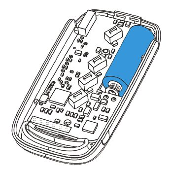
Table of contents

                                                                                                                      ENG
Technical specifications
         General Specifications ........................................................... Page 4
         PLP-REM-350 overview ......................................................... Page 4
         Logic board .............................................................................. Page 5
Installation Instructions
         Single PLP-REM-350 unit ..................................................... Page 6
         Multiple PLP-REM-350 installation...................................... Page 7
Operation modes .................................................................................. Page 8
DIP switch functionalities .................................................................... Page 9
Transmitter functions
         Operation mode: PLC ............................................................ Page 10
         Operatio mode: ON/OFF........................................................ Page 10
         Replacing transmitter keypad ............................................... Page 11
         Pairing the handheld transmitter ......................................... Page 11
DMX 512 communication
         Single PLP-REM-350 unit ..................................................... Page 12
         Multiple PLP-REM-350 installation ..................................... Page 13
RS-485 communication
         Single PLP-REM-350 unit ..................................................... Page 14
RS-485 command set........................................................................... Page 15
RESET procedure ................................................................................... Page 16
Transmitter battery................................................................................. Page 16
Troubleshooting ..................................................................................... Page 17
Pool light wiring instructions .............................................................. Page 18
Wiring remark ......................................................................................... Page 20

                                                                                                                  3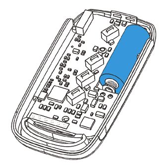
Technical specifications
General specifications
Input Voltage: 230 VAC 50Hz
Output Voltage: 12 VAC
Transformer VA rating: 350VA
Max output Power: 350 VA (12 VAC / 25A)
Max rating relay contact A &B 16A / 250 VAC
Max switching power A & B 4000VA
RF band 868 MHz
Ambient Air Temperature: 0°C to +40°C
Humidity 10% to 90% RH - non condensing
Ingress protection rate: IP54
IEC Protection Class: Class II
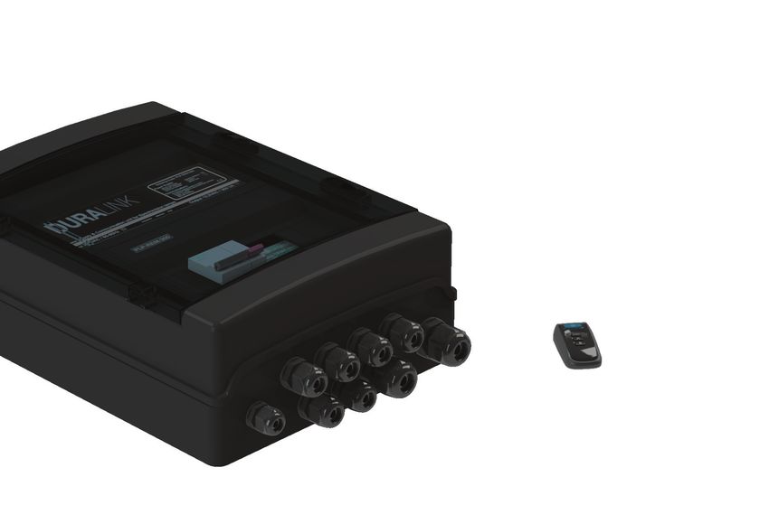
PLP-REM-350 overview
PLP-REM-350
12 VAC
Transformer
Integrated toroïdal Logic board
Transformer 350VA For details:
see next page
12VAC connection
Circuit breakers terminals
To connect the pool
lights
4
Logic board

                                                                                                                 ENG
     DMX Address dial       DIP switch                                   DuraLink RF board
     To choose the          To select controller functionalities         For wireless communication
     DMX start address

                                         (1)                       DuraLink

                                         (2)
                                                                                          Pairing / RESET
                                                                                          button

                                                                                          SD card slot
                                                                                          For firmware updates

                                               (4)     (5)
                                                             (6)                          CAN bus
              (3)

                                                                                          RS-485
                                                          (7)
                                                                                          connection
                                                                                          To connect to
                                                                      (8)                 home automation
                                                                                          system
                                                                                          (see page 16)

      12VAC connection                   A/B output                   DMX input/outpout
      terminals                          For auxiliary circuits       The PLP-REM can act
      To connect the pool                Acts as a SPST               as a DMX receiver with
      lights                             (single-pole, single-        DMX passthrough
                                         throw) switch

Status LED’s:
(1) General status                                                   (5) Switch B status (Green = ON)
    Green = OK                                                       (6) CAN status
    Red = error overvoltage or overcurrent                           (7) RS-485 signal
(2) Pairing / RESET status                                           (8) DMX signal
(3) 12VAC to Pool lamps (Green = ON)
(4) Switch A (Green = ON)

                                                                                                            5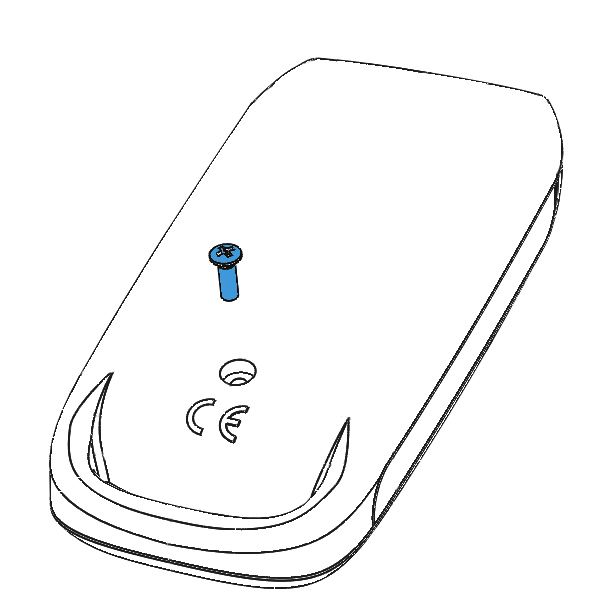
Installation Instructions

Single PLP-REM-350 unit

. Connect a 230VAC power source to the 230VAC terminals of the
    PLP-REM-350. Connect the pool lights to the 12VAC connection terminal
    block in the PLP-REM-350.
. The PLP-REM-350 has a 350VA transformer built in. The total power load
    of pool lights (+ cable losses) may not exceed this.

                              PLP-REM-350

                                                           Connect the pool
                                                           lights to the 12VAC
     Connect the                                           terminals
     230VAC power
     source to the
     circuit breaker

                         230VAC

6
Multiple PLP-REM-350 installation

                                                                                               ENG
For extended installations (total lamp power > 350VA), multiple PLP-REM-
350’s can be linked together. This way, a perfect synchronisation of all pool
lights is still guaranteed.
The PLP-REM-350’s need to communicate with each other, to ensure all the
lamps are in perfect sync.
Connect the PLP-REM-350’s with each other using the CAN bus:
Connect the CAN terminals of the first PLP-REM-350 with the CAN terminal
of the second PLP-REM-350*.
If more than 2 PLP-REM-350’s are necessary, simply daisy chain each CAN
terminal with the one from the next PLP-REM-350 (see below).
Respect the polarity of the terminals! (CAN L & H)
Next, set the DIP switches on the PLP-REM-350’s to the correct MASTER/
SLAVE setting. The first PLP-REM-350 will be the MASTER. All the others will
be SLAVE’s. Refer to page 9 for Master/Slave DIP switch info.

     In a Master/Slave setup, only the PLP-REM-350 that is set as MASTER
 ! will react to transmitter commands. Any additional transmitters will
     need to be paired with this MASTER PLP-REM-350

         set as MASTER                    set as SLAVE                       set as SLAVE

                                     CAN BUS

    PLP-REM-350                      PLP-REM-350                        PLP-REM-350

230VAC                           230VAC                             230VAC

* We recommend using a shielded twisted pair cable (min. 0,5mm² - up to 200m) to connect
  multiple PLP-REM-350’s using the CAN bus.

                                                                                           7
Operation Modes

The PLP-REM-350 controller has 2 main operation modes:
“ON/OFF control mode” & “PLC control mode”. Each mode has it’s own
functionalities:

                                     ON/OFF                        PLC

     Compatible lamps

    Switch lamps ON/OFF                YES                         YES

     Change lamp color                 YES   (1)
                                                                  YES(1)

    Operate Relay A & B                YES                         YES

       Dimming lamps                    NO                        YES(1)

        DMX control                     NO                         YES

       RS-485 control                  YES(2)                      YES

     Dip switch setting              DIP 1 ON                   DIP 1 OFF

    Remote keypad type(3)

1) Only for RGB lamps
2) In ON/OFF control mode, only a few RS-485 commands are available (see p 15)
3) Depending on which control mode is selected, the keypad of the transmitter needs
   to be changed

8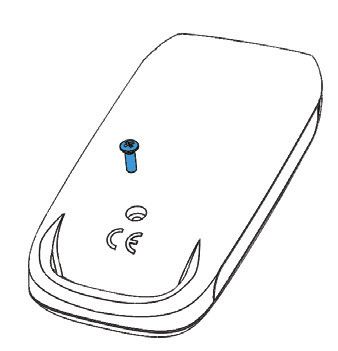
DIP switch functionalities

                                                                                            ENG
The DIP switch on the main circuit board of the PLP-REM-350 allows the
user to customise the way the PLP-REM-350 operates.
     CAUTION: Always switch off the main power supply to the
     		       PLP-REM-350 before changing the DIP switches

            PLP-REM-350

                                    ON position

                                    OFF position

                                                                DIP SWITCH

 function                                setting     1     2     3     4      5     6

                                   ON/OFF           ON
 Operation Mode
                                   PLC              OFF
                                   PULSE mode             ON
 Relay A
                                   TOGGLE mode            OFF
                                   PULSE mode                    ON
 Relay B
                                   TOGGLE mode                  OFF
                                   FAST                               ON
 Fast DMX setting *
                                   STANDARD                           OFF
                                   NO LOOP                                   ON
 DMX
                                   LOOP                                      OFF
                                   SLAVE                                           ON
 MASTER/SLAVE mode
                                   MASTER                                          OFF

* Fast DMX setting
  Only for Adagio Pro lamps from 2018 and onwards

                                                                                        9
Transmitter functions
OPERATION MODE: PLC (default mode)
Short push (< 1 sec):
Toggle all lamps ON or OFF (1)
Long push (> 2 sec(2)):
(1)
All lamps & “12VAC TO LAMPS” relay are turned OFF
Short push:
Go to next color program
Long push:
Toggle output A ON/OFF
Short push:
Go to the previous color program
Long push:
Toggle output B ON/OFF
Short push:
Select next dimming level:
100% -- 50% -- 25% ---> 100% -- ...
Long push:
Set lamps to Program 1 (blue) & full brightness
OPERATION MODE: ON/OFF
Short push (< 1 sec):
Toggle all lamps ON or OFF
Short push:
Go to next color program
Long push:
Auto sync procedure (3)
Short push:
Toggle output A ON/OFF
Long push:
/
Short push:
Toggle output B ON/OFF
Long push:
/
(1) Lamp ON or OFF status is memorized after power down
(2) The green LED in the transmitter will light up as soon as you start pressing a button, and will stop
after 2 seconds, so you know exactly when to release the button.
(3) The lamps will be turned off for 30 seconds and then switched ON/OFF 3 times. This will set all
lamps to program 1: blue
10Replacing transmitter Keypad
ENG
Depending on which control mode is selected, the keypad of the transmitter
needs to be changed:
• Remove the philips head screw and open the transmitter
• Replace the Keypad in the top part of the transmitter housing
• Reassemble in reverse order
Keypad for
PLC mode
Keypad for
ON/OFF mode
Pairing the handheld transmitter to the PLP-REM-350
All handheld transmitters are already paired in the factory and ready to use. In
case a problem arises, the pairing process can be done as below:
1) Press the pairing button on the circuit board, inside the PLP-REM-350
---> The BLUE LED will start to blink
2) Within 25 seconds, push any button on the handheld transmitter.
---> If the remote is paired correctly, the BLUE LED will flash slowly for 5 times
---> UNPAIRING:
See RESET procedure: page 16
DuraLink
Pairing Indicator LED
Pairing button
(blue)
11DMX 512 communication
Single PLP-REM-350 unit
1) Make sure DIP switch 1 is switched OFF.
2) Make sure the lights are turned ON with the remote first.
PLP-REM-350
DMX PANEL
Address dial
Connect DMX
panel
to DMX IN (+/-)
230VAC
Address dial setup
Setting the DMX address of the PLP-REM-350:
Select the desired number on the address dial. The chosen number deter-
mines the DMX addresses of the PLP-REM-350 & lamps.
Each lamp uses 3 bytes of DMX data (R-G-B), and all lamps receive the same
DMX data from the PLP-REM-350.
Address dial
position 0 1 2 ...
R G B R G B R G B ...
DMX
1 2 3 4 5 6 7 8 9 ...
address
The DMX start address can be overruled by using the RS-485 command:
“set DMX start address” (see page 17)
! Remark:
When in DMX512 operation, the handheld transmitter can still select one of three dim-
ming levels and can still switch the lamps. This can not be overridden by DMX512 data.
12Multiple PLP-REM-350 installation
ENG
1) Connect the DMX panel to the “DMX IN” port of the first PLP-REM-350
2) Connect the PLP-REM-350’s with each other (open loop):
DMX OUT --> DMX IN (polarized terminals + -)
3) Set the DMX address for each PLP-REM-350 via the address dial.
- Option 1: All PLP-REM-350’s can be set to the same address:
This implies that all lamps will receive the same DMX data,
And will all operate identically
- Option 2:PLP-REM-350’s can be set to different addresses:
Each PLP-REM-350 will have it’s own group of connected lamps
that will operate identically.
However, since each PLP-REM-350 has it’s own unique address,
the different lamp groups can be controlled separately
DMX PANEL
Address dial Address dial Address dial
PLP-REM-350 PLP-REM-350 PLP-REM-350
230VAC 230VAC 230VAC
13RS-485 communication
Single PLP-REM-350 unit
1) Make sure DIP switch 1 is switched OFF.
2) Make sure the lights are turned ON with the remote first.
3) Connect the RS-485 source to the “485” port on the PLP-REM-350
4) Communication settings: 9600, 8, 1, n
5) Command list: see page 15
PLP-REM-350 RS-485 Source
230VAC
Multiple PLP-REM-350 installation
1) Connect the PLP-REM-350’s with each other via the CAN bus (see page 7)
2) Make sure DIP switch 1 is switched OFF
3) Make sure the lights are turned ON with the remote first.
4) Connect the first PLP-REM-350 with the RS-485 source like described
above. This PLP-REM will be the Master.
5) Communication settings & command list: see page 15
14available in available in
Command Command Remark Example ON/OFF mode PLC mode
Lamps OFF PL0 All lamps OFF X X
Lamps ON PL1 All lamps ON X X
Program UP PsU Jump to next program X X
Program Down PsD Return to previous program X
xx is the decimal representation
Set Program PSxx PS06 = jump to program 6 X
of the program number (01 - 14)
Auto sync procedure PsS executes the auto sync procedure (see page 10) X X
White 1 PW1 Jump to White 1 (program 12) X
White 2 PW2 Jump to White 2 (program 13) X
RS-485 Command set
White 3 PW3 Jump to White 3 (program 14) X
1) PC255128064 = Full output level on Red color, half out-
rrr, ggg and bbb are the decimal representation put level on Green color, 1/4 output level on Blue color
Set RGB PCrrrgggbbb X
of the RGB value (with leading zero’s) 2) PC255255255 = All colors at full output level
3) PC000000000 = All colors OFF
set the OUTPUT value of the lamp in % (000 -
Set Dim value PDxxx PD075 = 75% output level (on all LED’s) X
100)
PA035E = set DMX start address to 35 [35(R), 36(G),
set DMX startAdress PAxxxyz y = ‘e’ or ‘E’ X
37(B)]
Set color in percentage Pprgbe variable size, rgb = ASCII 0-255, e = end character Pp25050100e = Red 25%, Green 50%, Blue 100% X
Set color in hex Pcrgbe variable size, rgb = ASCII 0-255, e = end character Pc64128255e = Red 25%, Green 50%, Blue 100% X
x = 1 (ON), 0 (OFF), P (Pulse) !this overrules
Relay A control PRAx PRA1 = Relay A ON PRA0 = Relay A OFF X X
dipswitch
x = 1 (ON), 0 (OFF), P (Pulse) !this overrules
Relay B control PRBx PRB1 = Relay B ON PRB0 = Relay B OFF X X
dipswitch
ON/OFF relay control PRMx x = 1 (ON), 0 (OFF) PRM1 = Relay ON/OFF control ON X X
PT035 = Set white color temperature to 3500K (in steps
Color temperature PTxyz x = ten thousand ; y = thousand ; z = hundred X
15
of 500K)
ENGRESET procedure
RESET procedure for the control board
1) Make sure the PLP-REM-350 is powered ON
2) Press and hold the RESET button on the logic board
3) The blue LED will light up
4) Release the RESET button when the blue LED turns off
The control board has been RESET.
! And all transmitters have been unpaired.
DuraLink
Blue
LED
RESET
button
Transmitter battery
Replacing transmitter battery:
• Remove the philips head screw and open the transmitter
• Replace the battery, respecting the polarity
Battery type: A23 12V
+
16Troubleshooting
ENG
PROBLEM SOLUTION
The PLP-REM-350 doesn’t react • Perform a RESET procedure
to transmitter commands • Check the battery of the handheld
transmitter (see p.16)
• The transmitter is not paired-
correctly with the PLP-REM.
Repeat the pairing process
• Reduce the distance between hand-
held transmitter and PLP-REM-350
and/or remove obstacles
• Check the General status light on
the logic board. If it’s red, then
the secondary voltage is too high
(>14VAC) or there is a short circuit
• Check the LED on the small DURA-
LINK circuit board (top right cor-
ner). This LED needs to blink each
time a transmitter button is pressed.
If the LED works, there might be a
problem with the logic board
The pool lights don’t work • Perform a RESET procedure
or don’t change colors • Check if all connections are made
correclty according to the electrical scheme.
• Switch the PLP-REM-350 to ON/
OFF mode (DIP switch nr 1) and
check if the lamps work
Handheld transmitter does not • Buy a new TX868 transmitter that
function anymore after firmware has updated firmware
update of the PLP-REM-350 for
LinkTouch compatibility
17Pool light wiring instructions
WARNING
GB Cable installation guidelines
NL Richtlijnen voor bekabeling
DE Anleitung zur Verkabelung
FR Instructions de câblage
IT Istruzioni di collegamento
ES Instrucciones para ajuste del cableado
Please refer to the manual of your DURAVISION® pool light
Manual downloads:
www.duratech.be/downloads
Not following the instructions for cable cross section and transformer VA ratings may result in lamp malfunctioning and may
result in having to rewire the installation. The manufacturer's warranty does not apply in this situation.
Please refer to the manual of your DURAVISION pool light for detailed
information about cable cross section and maximum length.
18Wiring remarks
1. Third party equipment such as frequency inverters and electric motors
can generate excessive noise on the 230VAC / 400VAC power line.
This noise might be injected into the adjacent 12VAC power line and
disturb the power line communication towards the DURAVISION lights.
Keep 230VAC / 400VAC power line cables at least 50cm separated over their full
! length from the 12VAC power line towards any RGB lights
Do not mix 12VAC and 230VAC / 400VAC power line cables into the same cable
! trays
2. Floating cores in a multi-core cable are not allowed because it disturbs
PLC communication.
We recommend using 2 CORE cables for all Adagio Pro lights to avoid PLC
! communication issues
Pool
Pool
house
12VAC to lamps
(**)
230VAC Min. 50cm
230VAC / 400VAC to third party equipment
(**) Do not mix 12VAC and 230VAC / 400VAC power line cables into the
same cable trays
1920
Inhoudstafel

Technische specificaties
         Algemene Specificaties .......................................................... Pagina 22
         PLP-REM-350 overzicht ........................................................ Pagina 22
         Controller board...................................................................... Pagina 23
Installatie Instructies
         Enkele PLP-REM-350 unit ..................................................... Pagina 24
         Installatie met meerdere PLP-REM-350’s .......................... Pagina 25

                                                                                                                    NL
Werkingsmodus ..................................................................................... Pagina 26
DIP schakelaar functies ........................................................................ Pagina 27
Afstandsbediening functies
         Werkingsmodus: PLC.............................................................. Pagina 28
         Werkingsmodus: AAN/UIT..................................................... Pagina 28
         Klavier van afstandsbediening vervangen .......................... Pagina 29
         Afstandsbediening en controller koppelen........................ Pagina 29
DMX 512 communicatie
         Enkele PLP-REM-350 unit ..................................................... Pagina 30
         Installatie met meerdere PLP-REM-350’s .......................... Pagina 31
RS-485 communication
         Enkele PLP-REM-350 unit ..................................................... Pagina 32
RS-485 commando’s ............................................................................ Pagina 33
RESET procedure ................................................................................... Pagina 34
Afstandsbediening batterij ................................................................... Pagina 34
Probleemoplossing................................................................................ Pagina 35
Kabelinstructies ..................................................................................... Pagina 36
Kablering opmerking............................................................................. Pagina 38

                                                                                                               21
Technische specificaties
Algemene specificaties
Ingangsspanning: 230 VAC 50Hz
Uitgangsspanning: 12,5 VAC
Transformator vermogen: 350VA
Max uitgangsvermogen: 350 VA (12 VAC / 25A)
Max stroom relais contact A &B 16A / 250 VAC
Max schakel vermogen A & B 4000VA
RF band 868 MHz
Omgevingstemperatuur: 0°C to +40°C
Vochtigheidsgraad: 10% to 90% RH - non condensing
IP code: IP54
IEC beschermingsklasse: Class II
PLP-REM-350 overzicht
PLP-REM-350
12 VAC
Transformator
Geïntegreerde Controller board
ringkern Voor details:
transformator 350VA zie volgende pagina
12VAC Aansluiting
Zekeringen Om de zwembad-
verlichting op aan te
sluiten
22Controller bord
DMX adres toewijzer DIP schakelaar DuraLink RF board
Om het DMX start adres Om de controller functies te Voor draadloze communicatie
te kiezen selecteren
DuraLink
(2)
RESET KNOP
NL
SD card slot
Voor firmware updates
(4) (5)
(6) CAN bus
(3)
RS-485
(7)
connectie
Om te verbinden met
(8) domotica systemen
(zie pagina 36)
12VAC aansluitklemmen A/B uitgang DMX ingang/uitgang
Om de zwembadverlichting Voor additionele circuits. De PLP-REM kan werken als DMX
op aan te sluiten Gedraagt zich als een SPST ontvanger (met DMX doorgang-
(sinlge-pole, single-throw) signaal)
schakelcontact
Status LED’s:
(1) Algemene status (5) Schakelcontact B status
Groen = OK (Groen = AAN)
Rood = overvoltage of overcurrent (6) CAN status
(2) RESET status (7) RS-485 signaal
(3) 12VAC naar zwembadverlichting (8) DMX signaal
(Groen = AAN)
(4) Schakelcontact A (Groen = AAN)
23Installatie instructies
Enkele PLP-REM-350 unit
. Verbind de 230VAC aansluiting van de PLA-REM-350 met de netspanning
Verbind de zwembadverlichting met de 12VAC aansluiting van de
PLP-REM-350.
. The PLP-REM-350 heeft een ingebouwde 350VA transformator. Het totale
vermogen van de zwembadverlichting (+kabel verliezen) mag dit niet over
schrijden.
Kijk in de handleiding van het gekozen type zwembadverlichting
! om te weten hoeveel VA elke lamp nodig heeft.
PLP-REM-350
Verbind de zwembad-
verlichting met de
12VAC klemmen
Verbind de 230V
netstpanning
met de zekering
230VAC
24Installatie met meerdere PLP-REM-350’s
Voor uitgebreide installaties (totale vermogen van de lampen > 350VA)
kunnen meerdere PLP-REM-350’s met elkaar verbonden worden. Op deze
manier blijft een perfecte synchronisatie van alle lampen gegarandeerd.
De PLP-REM-350’s moeten met elkaar kunnen communiceren, om zeker te
zijn dat alle lampen synchroon kunnen lopen.
Verbind de PLP-REM-350’s met elkaar via de CAN bus:
Verbind de CAN klemmen van de eerste PLP-REM-350 met de CAN klem-
men van de tweede PLP-REM-350, verbind dan de tweede met de derde,
enzovoort... (zie tekening onder)*
Respecteer de polariteit van de aansluitklemmen! (CAN L & H)
NL
Vervolgens moeten de DIP switches van de PLP-REM-350’s op de correcte
positie (MASTER/SLAVE) gezet worden. De eerste PLP-REM-350 is de Master.
Alle anderen zijn Slaves. Zie pagina 29 voor Master/Slave DIP switch info.
In een Master/Slave opstelling reageert enkel de PLP-REM-350 die
! ingesteld is als MASTER op de commando’s van de afstandsbediening.
Eventuele extra zenders moeten dus worden gekoppeld aan deze
MASTER PLP-REM-350
instellen als MASTER instellen als SLAVE instellen als SLAVE
CAN BUS
PLP-REM-350 PLP-REM-350 PLP-REM-350
230VAC 230VAC 230VAC
* We raden aan om een ‘shielded twisted pair’ kabel te gebruiken (min. 0,5mm² - tot 200m) om
verschillende PLP-REM-350’s te verbinden via de CAN bus.
25Werkingsmodus
De PLP-REM-350 kan gebruikt worden in 2 hoofd werkingsmodi:
“AAN/UIT bedieningsmodus” & “PLC bedieningsmodus”. Elke modus heeft
een aantal specifieke functies:
AAN/UIT PLC
Compatibele lampen
schakel lampen AAN/UIT JA JA
Verander kleur van lamp JA (1)
JA(1)
Bedien Relais A & B JA JA
Dimmen van de lampen NEE JA(1)
DMX sturing NEE JA
RS-485 sturing JA(2) JA
Dip switch positie DIP 1 AAN DIP 1 UIT
Type klavier
afstandsbediening(3)
1) Enkel voor RGB lampen
2) In AAN/UIT bedieningsmodus zijn slechts enkele RS-485 commando’s beschikbaar
(zie p 33)
3) Afhankelijk van de gekozen werkingsmodus, moeten de rubber toetsen van de
afstandsbediening verwisseld worden (meegeleverd in verpakking).
26DIP switch functies
De DIP switch op het moederbord van de PLP-REM-350 laat toe om een
aantal functies van de PLP-REM-350 aan te passen:
WAARSCHUWING: Zorg ervoor dat de voedingsspanning van de
PLP-REM-350 uitgeschakeld is, vooraleer de DIP
switches te veranderen
PLP-REM-350
NL
AAN positie
UIT positie
DIP SWITCH
functie setting 1 2 3 4 5 6
AAN/UIT AAN
Werkingsmodus
PLC UIT
PULS modus AAN
Relais A
TOGGLE modus UIT
PULS modus AAN
Relais B
TOGGLE modus UIT
SNEL AAN
SNELLE DMX instelling *
STANDAARD UIT
GEEN LOOP AAN
DMX
LOOP UIT
SLAVE AAN
MASTER/SLAVE modus
MASTER UIT
* Snelle DMX instelling
Enkel voor Adagio Pro lampen vanaf 2018 en later
27Afstandsbediening functies
WERKINGSMODUS: PLC (standaard modus)
Kort drukken (< 1 sec):
Zet de lampen AAN of UIT(1)
Lang drukken (> 2 sec(2)):
Zet alle lampen & de “12VAC TO LAMPS” relais UIT (1)
Kort drukken:
Ga naar het volgende kleurprogramma
Lang drukken:
Zet de uitgang A AAN/UIT
Kort drukken:
Ga naar het vorige kleurprogramma
Lang drukken:
Zet de uitgang B AAN/UIT
Kort drukken:
Selecteer het volgende dim niveau:
100% -- 50% -- 25% ---> 100% -- ...
Lang drukken:
Zet de lampen op programma 1 (blauw) met
100% dim niveau (max helderheid)
WERKINGSMODUS: AAN/UIT
Kort drukken (< 1 sec):
Zet de lampen AAN of UIT(1)
Kort drukken:
Ga naar het volgende kleurprogramma
Lang drukken:
Automatische sync procedure (3)
Kort drukken:
Zet de uitgang A AAN/UIT
Lang drukken:
/
Kort drukken:
Zet de uitgang B AAN/UIT
Lang drukken:
/
(1) De laatste status van de lampen (AAN of UIT) wordt onthouden bij een stroomonderbreking
(2) De groene LED in de afstandsbediening licht op zodra je een knop indrukt, en gaat uit na 2 seconden
zodat je exact weet wanneer je de knop mag loslaten.
(3) De lampen worden eerst UIT gezet gedurende 30 seconden en daarna 3x AAN/UIT gezet. De lampen
worden hierdoor gesynchroniseerd en komen op kleurprogramma 1 te staan (blauw).
28Klavier van afstandsbediening vervangen
Afhankelijk van de gekozen werkingsmodus, kan het klavier van de af-
standsbediening vervangen worden:
• Verwijder de kruis schroef en open de afstandsbediening
• Vervang het klavier van de afstandsbediening
• Monteer het geheel terug in omgekeerde volgorde
NL
Klavier voor
PLC modus
Klavier voor
AAN/UIT modus
Afstandsbediening en controller koppelen
De afstandsbediening is reeds gekoppeld van in de febriek. In probleem-
gevallen kan men de afstandsbediening ook manueel koppelen:
1) Druk op de “koppel knop” binnenin de PLP-REM-350
---> De BLAUWE LED begint te knipperen.
2) Druk op eender welke knop van de afstandsbediening binnen de 25sec.
---> Als de afstandsbediening correct is gekoppeld, knippert de BLUE LED 5 keer
langzaam
---> ONTKOPPELEN:
Zie RESET procedure: pagina 34
Blauwe LED Koppel knop
29DMX 512 communicatie
Enkele PLP-REM-350 unit
1) Zorg ervoor dat DIP schakelaar 1 is uitgeschakeld.
2) Zorg ervoor dat de lampen aan staan via de afstandsbediening.
PLP-REM-350 DMX PANEL
Adres
toewijzer
verbindt DMX
paneel met
DMX IN (+/-)
230VAC
Adres toewijzer instelling
DMX adres van de PLP-REM-350 instellen:
Kies een positie van de adres toewijzer. Het gekozen cijfer bepaalt de DMX
adressen van de PLP-REM-350 & lampen.
Elke lamp gebruikt 3 bytes DMX data (R-G-B) en alle lampen ontvangen de-
zelfde DMX data van de PLP-REM-350.
Adres toewijzer
positie 0 1 2 ...
R G B R G B R G B ...
DMX
1 2 3 4 5 6 7 8 9 ...
adres
Het DMX start adres kan overschreven worden, door het RS-485 commando
“set DMX start address” te gebruiken (zie pagina 33).
! Opmerking:
In DMX512 bedrijf, kan de je met de afstandsbediening nog steeds één van de drie dim
niveaus selecteren en nog steeds de lampen schakelen. Dit kan niet verworpen worden
door DMX512 gegevens
30Installatie met meerdere PLP-REM-350’s
1) Verbindt het DMX paneel met de “DMX IN” poort van de eerste PLP-REM-350
2) Verbindt de PLP-REM-350’s met elkaar zoals op onderstaande foto
DMX OUT --> DMX IN (gepolariseerde aansluiting + -)
3) Stel het DMX adres in voor elke PLP-REM-350 via de adres toewijzer.
- Optie 1: Alle PLP-REM-350’s zitten op hetzelfde adres:
Dit zorgt ervoor dat alle lampen dezelfde DMX data ontvangen,
en zich allemaal identiek gedragen.
- Optie 2: De PLP-REM-350’s zitten op verschillende adressen:
Elke PLP-REM-350 heeft zijn eigen “groep” lampen die zich
onderling identiek gedragen.
NL
En elke PLP-REM-350 kan dan nog eens afzonderlijk aan-
gestuurd worden.
DMX PANEL
Adres toewijzer Adres toewijzer Adres toewijzer
PLP-REM-350 PLP-REM-350 PLP-REM-350
230VAC 230VAC 230VAC
31RS-485 communicatie
Enkele PLP-REM-350 unit
1) Zorg ervoor dat DIP schakelaar 1 is uitgeschakeld.
2) Zorg ervoor dat de lampen aan staan via de afstandsbediening.
3) Verbindt de RS-485 bron met de “485” poort op de PLP-REM-350
4) Communicatie instellingen: 9600, 8, 1, n
5) Commando lijst: zie pagina 33
PLP-REM-350 RS-485 Bron
230VAC
Installatie met meerdere PLP-REM-350’s
1) Verbindt de PLP-REM-350’s met elkaar via de CAN bus (zie pagina 27)
2) Zorg ervoor dat DIP schakelaar 1 is uitgeschakeld
3) Zorg ervoor dat de lampen aan staan via de afstandsbediening
4) Verbindt de eerste PLP-REM-350 met de RS-485 bron zoals hierboven
beschreven. Deze PLP-REM-350 is de Master.
5) Communicatie instellingen en commando lijst: zie boven
32available in available in
Command Command Remark Example ON/OFF mode PLC mode
Lamps OFF PL0 All lamps OFF X X
Lamps ON PL1 All lamps ON X X
Program UP PsU Jump to next program X X
Program Down PsD Return to previous program X
xx is the decimal representation
Set Program PSxx PS06 = jump to program 6 X
of the program number (01 - 14)
executes the auto sync procedure (see pagina
Auto sync procedure PsS X X
10)
White 1 PW1 Jump to White 1 (program 12) X
RS-485 Commando’s
White 2 PW2 Jump to White 2 (program 13) X
White 3 PW3 Jump to White 3 (program 14) X
1) PC255128064 = Full output level on Red color, half out-
rrr, ggg and bbb are the decimal representation put level on Green color, 1/4 output level on Blue color
Set RGB PCrrrgggbbb X
of the RGB value (with leading zero’s) 2) PC255255255 = All colors at full output level
3) PC000000000 = All colors OFF
set the OUTPUT value of the lamp in % (000 -
Set Dim value PDxxx PD075 = 75% output level (on all LED’s) X
100)
PA035E = set DMX start address to 35 [35(R), 36(G),
set DMX startAdress PAxxxyz y = ‘e’ or ‘E’ X
37(B)]
Set color in percentage Pprgbe variable size, rgb = ASCII 0-255, e = end character Pp25050100e = Red 25%, Green 50%, Blue 100% X
Set color in hex Pcrgbe variable size, rgb = ASCII 0-255, e = end character Pc64128255e = Red 25%, Green 50%, Blue 100% X
x = 1 (ON), 0 (OFF), P (Pulse) !this overrules
Relay A control PRAx PRA1 = Relay A ON PRA0 = Relay A OFF X X
dipswitch
x = 1 (ON), 0 (OFF), P (Pulse) !this overrules
Relay B control PRBx PRB1 = Relay B ON PRB0 = Relay B OFF X X
dipswitch
ON/OFF relay control PRMx x = 1 (ON), 0 (OFF) PRM1 = Relay ON/OFF control ON X X
33
PT035 = Set white color temperature to 3500K (in steps
Color temperature PTxyz x = ten thousand ; y = thousand ; z = hundred X
of 500K)
NLRESET procedure
RESET procedure voor het controller bord
1) Zorg ervoor dat de PLP-REM-350 AAN staat.
2) Druk op de RESET knop op het controller board.
3) De blauwe LED gaat branden
4) Laat de RESET knop los van zodra de blauwe LED uitgaat
Het controller board is nu ge-RESET.
! Alle afstandsbedieningen zijn nu ontkoppeld.
DuraLink Blauwe
LED
RESET
knop
Afstandsbediening batterij
Batterij vervangen:
• Verwijder de kruiskop schroef en open de afstandsbediening
• Vervang de batterij en respecteer de polariteit.
Batterij type: A23 12V
+
-
34Probleemoplossing
PROBLEEM OPLOSSING
De PLP-REM-350 reageert niet • Voer een RESET procedure uit
op commando’s van de af- • Controleer de batterij van de af-
standsbediening standsbediening (zie pagina 34)
• De afstandsbediening is niet cor-
rect gekoppeld met de controller.
Herhaal de koppel procedure (zie
pagina 32)
• Verminder de afstand tussen de af-
standsbediening en de controller
NL
en/of verwijder obstakels
• Controleer de algemene status LED
op het controller board. Als deze
rood is dan is de secundaire span-
ning te hoog (>14VAC) of er is een
kortsluiting.
• Controleer de LED op de kleine
DURALINK printplaat (rechter
bovenhoek). Deze LED moet knip-
peren, elke keer er op een knop
van de afstandsbediening gedrukt
wordt. Als de LED werkt, is er mo-
gelijks een probleem met het con-
troller board
De zwembadverlichting werkt • Voer een RESET procedure uit
niet • Verifieer of alle verbindingen ge-
maakt zijn zoals op de electrische
schema’s
• Zet de PLP-REM-350 in AAN/UIT
mode (DIP switch nr 1) en con-
troleer of de lampen werken
De afstandsbediening werkt niet • Koop een nieuwe TX868 af-
meer na een firmware update van standsbediening met geupdate
de PLP-REM-350 voor LinkTouch firmware
compatibiliteit
35Kabelinstructies
WARNING
GB Cable installation guidelines
NL Richtlijnen voor bekabeling
DE Anleitung zur Verkabelung
FR Instructions de câblage
IT Istruzioni di collegamento
ES Instrucciones para ajuste del cableado
Please refer to the manual of your DURAVISION® pool light
Manual downloads:
www.duratech.be/downloads
Not following the instructions for cable cross section and transformer VA ratings may result in lamp malfunctioning and may
result in having to rewire the installation. The manufacturer's warranty does not apply in this situation.
Voor gedetailleerde informatie in verband met kabelsecties en maximum
lengtes verwijzen we graag naar de handleiding van uw DURAVISION
zwembadlamp.
36Kablering opmerkingen
1. Andere toestellen zoals frequentie inverters of electrische motors
kunnen veel ruis veroorzaken op de 230VAC / 400VAC spanningslijn.
Het is mogelijk dat dit ruis geïnjecteerd wordt in een nabijgelegen
12VAC kabel, en dusdanig de communicatie naar de zwembadlampen
verstoord.
Houdt 230VAC / 400VAC voedingskabels uit de buurt van de 12VAC kabels
! van de lampen. De minimum afstand bedraagt 50cm, en dit over de gehele
lengte van de kabel
Zorg ervoor dat er geen 12VAC en 230VAC / 400VAC kabels samen in een-
! zelfde kabelgoot liggen
2. Stroomloze aders in een meeraderige kabel zijn niet toegestaan omdat
dit de PLC communicatie verstoort
We raden aan om 2-aderige kabels te gebruiken voor alle Adagio Pro lampen
! om PLC communcatie problemen te vermijden
Zwembad
Pool
house
12VAC naar lampen
(**)
230VAC Min. 50cm
230VAC / 400VAC naar andere toestellen
(**) Zorg ervoor dat er geen 12VAC en 230VAC / 400VAC kabels
samen in eenzelfde kabelgoot liggen
3738
Sommaire

Spécifications techniques
         Spécifications générales ........................................................ Page 40
         Aperçu du PLP-REM-350....................................................... Page 40
         Circuit imprimé ........................................................................ Page 41
Instructions d’installation
         Installation d’un seul appareil PLP-REM-350 .................... Page 42
         Installation de plusieurs appareils PLP-REM-350............. Page 43
Modes de fonctionnement .................................................................. Page 44
Fonctions du commutateur DIP ......................................................... Page 45
Fonctions de la télécommande
         Mode de fonctionnement: PLC............................................ Page 46
         Mode de fonctionnement: ON/OFF.................................... Page 46
         Remplacer le clavier de la télécommande ........................ Page 47
         Appairer la télécommande portable ................................... Page 47
Communication via DMX 512
         Avec un seul appareil PLP-REM-350  ..................................................... Page 48
         Avec plusieurs appareils PLP-REM-350               ..................................... Page 49

                                                                                                                 FR
Communication via RS-485
         Avec un seul appareil PLP-REM-350 .................................. Page 50
Jeu d’instructions pour RS-485 .......................................................... Page 51
Procédure de réinitialisation ............................................................... Page 52
Pile de la télécommande...................................................................... Page 52
Résolution des problèmes ................................................................... Page 53
Instructions de câblage de la piscine ................................................ Page 54
Instructions de câblage - remarque .................................................. Page 56

                                                                                                            39
Spécifications techniques
Spécifications générales
Tension d’entrée: 230 VAC 50Hz
Tension de sortie: 12,5 VAC
Puissance du transformateur: 350VA
Puissance de sortie maximale: 350 VA (12 VAC / 25A)
Valeurs maximales des contacts de relais A & B: 16A / 250 VAC
Puissance de commutation maximale A & B: 4000VA
Bande RF 868 MHz
Température ambiante: 0°C to +40°C
Humidité: 10 % à 90 % HR - sans
condensation
Indice de protection: IP54
Classe de Protection IEC: Class II
Aperçu du PLP-REM-350
PLP-REM-350
Transformateur
12 VAC
Transformateur Circuit imprimé
toroïdal de Pour plus de
350 VA intégré détails :
voir page suivante
Bornes de
Disjoncteurs raccordement 12
VAC
Pour raccorder les
lampes de la piscine
40Circuit imprimé
Molette d’adresse DMX Commutateur DIP Circuit Imprimé DuraLink RF
Pour sélectionner Pour sélectionner les fonctions du Pour communication sans fil
l’adresse de départ du DMX contrôleur
(1) DuraLink
(2)
Bouton de réinitialisation
Emplacement pour
carte SD
Pour les mises à jour
logicielles
(4) (5)
(6) Bus CAN
(3)
Connexion RS-485
(7)
Pour effectuer une
connexion au système
FR
(8) d’automatisation
domestique
(voir page 56)
Bornes de Sorties A/B Entrées/sorties DMX
raccordement 12 Pour des circuits auxilia- Le PLP-REM peut servir
VAC ires. Sert de commuta- de récepteur DMX avec
Pour raccorder les teur SPST (single-pole, intermédiaire DMX
lampes de la piscine single-throw)
Sorties A/B
Témoins LED :
(1) État général (5) Commutateur B
Vert = OK (VERT = allumé)
Rouge = Erreur surtension où court-circuit (6) État CAN
(2) RÉINITIALISATION (7) Signal RS-485
(3) 12 VAC vers les lampes de la piscine (8) Signal DMX
(VERT = allumé)
(4) Commutateur A (VERT = allumé)
41Instructions d’installation
Installation d’un seul appareil PLP-REM-350
. Raccordez une alimentation de 230 VAC aux bornes 230 VAC du
PLP-REM-350. Raccordez les lampes de la piscine au bornier de
raccordement 12 VAC dans le PLP-REM-350.
. Le PLP-REM-350 intègre un transformateur de 350 VA. La puissance totale
des lampes (+ pertes de câbles) de la piscine ne peut pas dépasser cette
valeur.
PLP-REM-350
Raccordez les
lampes de la piscine
Raccordez l’alimentation aux bornes 12 VAC
(230 VAC) au disjoncteur
230VAC
42Installation de plusieurs appareils PLP-REM-350
Pour des installations plus grandes (puissance totale des lampes > 350 VA),
plusieurs PLP-REM-350 peuvent être raccordés entre eux. Ainsi, une syn-
chronisation parfaite de toutes les lampes de la piscine reste garantie
Les PLP-REM-350 doivent pouvoir communiquer entre eux, de manière à
ce que toutes les lampes soient parfaitement synchronisées.
Raccordez les PLP-REM-350 entre eux via le bus CAN.
Raccordez les bornes CAN du premier PLP-REM-350 avec celles du second
PLP-REM-350*
Si plus de 2 PLP-REM-350 sont nécessaires, raccordez simplement chaque
borne CAN en parrallel avec celle du PLP-REM-350 suivant (voir ci-des-
sous). Veillez à respecter la polarité des bornes ! (CAN L & H)
Ensuite, réglez les commutateurs DIP des PLP-REM-350 sur le bon réglage
MAÎTRE / ESCLAVE. Le premier PLP-REM-350 sera le maître. Tous les autres
seront ESCLAVE. Reportez-vous à la page 49 pour les informations sur les
commutateurs DIP Maître/Esclave.
Dans une configuration Maître/Esclave, seul le PLP-REM-350 défini
! comme MAÎTRE réagit aux commandes de la télécommande. Toutes
les télécommandes supplémentaire devra être couplé avec ce MAÎTRE
PLP-REM-350
FR
définir comme MAÎTRE définir comme ESCLAVE définir comme ESCLAVE
CAN BUS
PLP-REM-350 PLP-REM-350 PLP-REM-350
230VAC 230VAC 230VAC
* Nous vous recommandons d’utiliser un câble à paire torsadée blindée (min. 0,5 mm² - jusqu’à
200 m) pour la connexion plusieurs PLP-REM-350 utilisant le bus CAN.
43Modes de fonctionnement
Le contrôleur PLP-REM-350 offre 2 modes de fonctionnement principaux :
« Mode de fonctionnement ON/OFF » & « Mode de fonctionnement PLC ».
Chaque mode offre ses propres fonctions :
ON/OFF PLC
Lampes compatibles
Allumer/éteindre les lampes OUI OUI
Changer la couleur de la lampe OUI (1)
OUI(1)
Contrôler les relais A & B OUI OUI
Régler l’intensité des lampes NON OUI(1)
Contrôle DMX NON OUI
Contrôle RS-485 OUI(2) OUI
Configuration du commutateur
DIP 1 ON DIP 1 OFF
DIP
Type de clavier
sur la télécommande(3)
1) Uniquement pour les lampes RGB
2) En mode commande ON/OFF, seules quelques commandes RS-485 sont
disponibles (voir page 51)
3) En fonction du mode de commande sélectionné, le clavier de la télécommande
doit être changé
44Fonctions du commutateur DIP
Le commutateur DIP intégré sur le circuit imprimé principal du PLP-REM-350
permet à l’utilisateur de personnaliser la manière dont le PLP-REM-350
fonctionne.
ATTENTION: Toujours couper l’alimentation électrique principale
PLP-REM-350 avant de changer les commutateurs DIP
PLP-REM-350
Position ON
Position OFF
DIP SWITCH
FR
fonction réglage 1 2 3 4 5 6
ON/OFF ON
Mode de fonctionnement
PLC OFF
Mode PULSE ON
Relais A
Mode TOGGLE OFF
Mode PULSE ON
Relais B
Mode TOGGLE OFF
RAPIDE ON
DMX rapide *
STANDARD OFF
PAS DE BOUCLE ON
DMX
BOUCLE OFF
ESCLAVE ON
Mode MAÎTRE/ESCLAVE
MAÎTRE OFF
* DMX rapide
Seulement pour les lampes Adagio Pro à partir de 2018.
45Fonctions de la télécommande
MODE DE FONCTIONNEMENT: PLC (mode par défaut)
Appuyer brièvement (< 1 sec) :
Allumer ou éteindre les lampes (1)
Appuyer longuement (> 2 sec(2)) :
Toutes les lampes & le relais “12VAC TO LAMPS” sont éteints (1)
Appuyer brièvement:
Aller au programme de couleur suivant
Appuyer longuement:
Allumer/éteindre la sortie A
Appuyer brièvement:
Aller au programme de couleur précédent
Appuyer longuement:
Allumer/éteindre la sortie B
Appuyer brièvement:
Sélectionner le réglage d’intensité suivant:
100% -- 50% -- 25% ---> 100% -- ...
Appuyer longuement:
Réglage des lampes sur le Programme 1 (bleu) & intensité maximale
MODE DE FONCTIONNEMENT: ON/OFF
Appuyer brièvement(< 1 sec):
Allumer ou éteindre les lampes (1)
Appuyer brièvement:
Aller au programme de couleur suivant
Appuyer longuement:
Procédure de synchronisation automatique (3)
Appuyer brièvement:
Allumer/éteindre la sortie A
Appuyer longuement:
/
Appuyer brièvement:
Allumer/éteindre la sortie B
Appuyer longuement:
/
(1) L’état des lampes (ON ou OFF) est mémorisé après la mise hors tension
(2) La LED verte de la télécommande s’allumera dès que vous appuierez sur un bouton et s’éteindra après 2
seconds, de façon à ce que vous sachiez exactement quand vous pouvez relâcher le bouton.
(3) Les lampes seront éteintes durant 30 secondes et ensuite allumées/éteintes 3 fois. Cela règlera toutes
les lampes sur le programme 1 : bleu
46Remplacer le clavier de la télécommande (sélection du mode de commande)
En fonction du mode de commande sélectionné, le clavier de la télécom-
mande doit être changé:
• Retirez la vis cruciforme et ouvrez la télécommande
• Remplacez le clavier dans la partie supérieure du boîtier de la
télécommande
• Réassemblez en ordre inverse
Clavier pour
mode PLC
Clavier pour
mode ON/OFF
Appairer la télécommande portable au PLP-REM-350
Toutes les télécommandes portables sont appairées au préalable en usine et prêtes à être util-
isées. Si un problème devait survenir, le processus d’appairage peut être réalisé comme suit :
FR
1) Appuyez sur le bouton d’appairage sur le petit circuit imprimé à l’intérieur du
PLP-REM-350.
---> La LED bleue va commencer à clignoter
2) Dans les 25 secondes qui suivent, appuyez sur n’importe quel bouton de la
télécommande portable.
---> Si la télécommande est correctement appariée, la LED
bleue clignotera lentement pendant 5 fois
---> UNPAIRING:
Voir la procédure RESET: page 52
DuraLink
Témoin d’appairage LED (BLEU)
Bouton d’appairage
47Communication via DMX 512
Avec un seul appareil PLP-REM-350
1) Assurez-vous que le commutateur DIP 1 est désactivé.
2) Assurez-vous que les lumières sont allumées en premier avec la
télécommande.
PLP-REM-350 PANNEAU DMX
Molette d’adresse
Raccordez le
panneau DMX
aux bornes
DMX IN (+/-)
230VAC
Réglage de la molette d’adresse
Définir l’adresse DMX du PLP-REM-350 :
Sélectionnez le chiffre désiré sur la molette d’adresse. Le chiffre choisi
détermine les adresses DMX du PLP-REM-350 et des lampes. Chaque lampe
utilise 3 octets de données DMX (R-G-B), et toutes les lampes reçoivent les
mêmes données DMX depuis le PLP-REM-350.
Position de la
molette d’adresse 0 1 2 ...
R G B R G B R G B ...
Adresse
1 2 3 4 5 6 7 8 9 ...
DMX
L’adresse DMX de départ peut être peut être annulée en utilisant la commande
RS-485 : “set DMX start address” (voir page 51)
! Remarque:
En fonctionnement DMX512, l’émetteur portable peut toujours sélectionner l’un des
trois niveaux de gradation et peut toujours commuter les lampes. Cela ne peut pas être
annulé par les données DMX512.
48Avec plusieurs appareils PLP-REM-350
1) Raccordez le panneau DMX au port « DMX IN » du premier PLP-REM-350
2) Raccordez les PLP-REM-350 entre eux (boucle ouverte) : DMX OUT -->
DMX IN (bornes polarisées + -)
3) Définissez l’adresse DMX pour chaque PLP-REM-350 via la molette
d’adresse.
- Option 1: Tous les PLP-REM-350 peuvent être réglés sur la même
adresse:
Cela implique que toutes les lampes recevront les mêmes
données DMX, et qu’elles fonctionneront toutes de la même
manière
- Option 2:Il est possible d’attribuer des adresses différentes
aux PLP-REM-350:
Chaque PLP-REM-350 aura son propre groupe de
lampes raccordées qui fonctionneront de manière identique.
Cela étant, vu que chaque PLP-REM-350 a sa propre adresse
unique, les différents groupes de lampes peuvent être
contrôlés séparément
Panneau DMX
FR
Molette Molette Molette
d’adresse d’adresse d’adresse
PLP-REM-350 PLP-REM-350 PLP-REM-350
230VAC 230VAC 230VAC
49Communication via RS-485
Avec un seul appareil PLP-REM-350
1) Assurez-vous que le commutateur DIP 1 est désactivé.
2) Assurez-vous que les lumières sont allumées en premier avec la
télécommande.
3) Raccordez la source RS-485 au port “485” sur le PLP-REM-350
4) Paramètres de communication: 9600, 8, 1, n
5) Liste de commandes: voir page 51
PLP-REM-350 source RS-485
230VAC
Avec plusieurs appareils PLP-REM-350
1) Connectez les PLP-REM-350 entre eux via le bus CAN (voir page 47)
2) Assurez-vous que le commutateur DIP 1 est désactivé
3) Assurez-vous que les lumières sont allumées via la télécommande
4) Connectez le premier PLP-REM-350 à la source RS-485 comme ci-dessus
décrit. Ce PLP-REM-350 est le maître.
5) Paramètres de communication et liste de commandes: voir ci-dessus
50available in available in
Command Command Remark Example ON/OFF mode PLC mode
Lamps OFF PL0 All lamps OFF X X
Lamps ON PL1 All lamps ON X X
Program UP PsU Jump to next program X X
Program Down PsD Return to previous program X
xx is the decimal representation
Set Program PSxx PS06 = jump to program 6 X
of the program number (01 - 14)
Auto sync procedure PsS executes the auto sync procedure (see page 10) X X
White 1 PW1 Jump to White 1 (program 12) X
White 2 PW2 Jump to White 2 (program 13) X
RS-485 Command set
White 3 PW3 Jump to White 3 (program 14) X
1) PC255128064 = Full output level on Red color, half out-
rrr, ggg and bbb are the decimal representation put level on Green color, 1/4 output level on Blue color
Set RGB PCrrrgggbbb X
of the RGB value (with leading zero’s) 2) PC255255255 = All colors at full output level
3) PC000000000 = All colors OFF
set the OUTPUT value of the lamp in % (000 -
Set Dim value PDxxx PD075 = 75% output level (on all LED’s) X
100)
PA035E = set DMX start address to 35 [35(R), 36(G),
set DMX startAdress PAxxxyz y = ‘e’ or ‘E’ X
37(B)]
Set color in percentage Pprgbe variable size, rgb = ASCII 0-255, e = end character Pp25050100e = Red 25%, Green 50%, Blue 100% X
Set color in hex Pcrgbe variable size, rgb = ASCII 0-255, e = end character Pc64128255e = Red 25%, Green 50%, Blue 100% X
x = 1 (ON), 0 (OFF), P (Pulse) !this overrules
Relay A control PRAx PRA1 = Relay A ON PRA0 = Relay A OFF X X
dipswitch
x = 1 (ON), 0 (OFF), P (Pulse) !this overrules
Relay B control PRBx PRB1 = Relay B ON PRB0 = Relay B OFF X X
dipswitch
ON/OFF relay control PRMx x = 1 (ON), 0 (OFF) PRM1 = Relay ON/OFF control ON X X
PT035 = Set white color temperature to 3500K (in steps
Color temperature PTxyz x = ten thousand ; y = thousand ; z = hundred X
51
of 500K)
FRProcédure de réinitialisation (RESET)
Procédure de réinitialisation du circuit imprimé
1) Assurez-vous que le PLP-REM-350 est sous tension
2) Appuyez et maintenez le bouton RÉINITIALISER sur la carte logique
3) La LED bleue s’allume
4) La LED bleue s’allumera. Relâchez la touche RÉINITIALISER lorsque la
LED bleue s’éteint
La carte de commande a été RÉINITIALISÉ.
! et tous les émetteurs ont été désaccouplés.
DuraLink LED
bleu
RÉINITIALISER
bouton
Pile de la télécommande
Remplacez la pile de la télécommande :
• Retirez la vis cruciforme et ouvrez la télécommande
• Remplacez la pile, en veillant à respecter la polarité
Type de pile : A23 12V
+
-
52Résolution des problèmes
PROBLÈME SOLUTION
Le PLP-REM ne réagit pas aux • Suivez la procédure de réinitialisa-
commandes de la tion
télécommande • Vérifiez la pile de la télécommande
portable (voir p. 52)
• La télécommande n’a pas été
appairée correctement avec le
PLP-REM. Répétez le processus
d’appairage (voir p. 52)
• Réduisez la distance entre la
télécommande portable et le
PLP-REM et/ou éliminez les
obstacles
• Vérifier le voyant d’état général sur
la carte logique. S’il est rouge, la
tension secondaire est trop élevée
(> 14VAC) ou il y a un court-circuit.
• Vérifiez la LED sur le petit circuit
imprimé DURALINK (coin supérieur
droit). Cette LED doit clignot-
FR
er chaque fois qu’un bouton de
l’émetteur est enfoncé. Si le voyant
fonctionne, il peut y avoir un prob-
lème avec la carte mère
Les lumières de la piscine ne • Suivez la procédure de réinitialisa-
fonctionnent pas tion
ou ne change pas de couleurs • Vérifiez si tous les raccordements
correctement ont été réalisés selon le schéma
électrique
• Mettez le PLP-REM en mode
ON/OFF (interrupteur DIP n ° 1)
et vérifiez si les lampes fonction-
nent.
L’émetteur à main ne fonctionne • Achetez un nouvel émetteur TX868
plus après la mise à jour du firm- avec firmware mis à jour
ware du PLP-REM-350 pour la
compatibilité LinkTouch
53Instructions de câblage de la piscine
WARNING
GB Cable installation guidelines
NL Richtlijnen voor bekabeling
DE Anleitung zur Verkabelung
FR Instructions de câblage
IT Istruzioni di collegamento
ES Instrucciones para ajuste del cableado
Please refer to the manual of your DURAVISION® pool light
Manual downloads:
www.duratech.be/downloads
Not following the instructions for cable cross section and transformer VA ratings may result in lamp malfunctioning and may
result in having to rewire the installation. The manufacturer's warranty does not apply in this situation.
Veuillez vous référer au manuel de votre lampe de piscine DURAVISION
pour des informations détaillées sur la section de câble et la longueur
maximale.
54Instructions de câblage - remarques
1. Autres équipements comme variateurs de fréquence ou les moteurs
électriques peuvent générer un bruit excessif sur la ligne électrique 230
VAC / 400 VAC.
Ce bruit pourrait être injecté dans la ligne électrique 12VAC adjacente et
perturber la communication des signaux vers les lumières DURAVISION
Gardez les câbles de ligne 230 VAC / 400 VAC au moins 50cm séparés sur
! leur longeur totale de la ligne 12 VAC vers toutes les lumières RGB
Ne pas mélanger les câbles de ligne 12 VAC et 230 VAC / 400 VAC dans les
! mêmes goulottes de câbles.
2. Des fils non-utilisés dans un cable multiconducteurs ne sont pas
autorisés cars ils pertubent la communication PLC.
Nous vous recommendons d’utiliser câbles à 2 fils pour toutes les lampes
! Adagio Pro afin d’éviter les problèmes de communication PLC
Piscine
Pool
house
12VAC vers lamps
(**)
230VAC Min. 50cm
230VAC / 400VAC vers autres équipements
(**) Ne pas mélanger les câbles de ligne 12 VAC et 230 VAC / 400
VAC dans les mêmes goulottes de câbles.
5556
Inhalt

Technische Angaben
         Allgemeine Spezifikation ....................................................... Seite 58
         PLP-REM-350 Übersicht ....................................................... Seite 58
         Logikplatine .............................................................................. Seite 59
Installationsanweisungen
         Einzelinstallation der PLP-REM-350 Einheit ..................... Seite 60
         Mehrfachinstallation von PLP-REM-350 ............................ Seite 61
Betriebsarten .......................................................................................... Seite 62
Funktionalitäten des DIP-schalters .................................................... Seite 63
Funktionen des Senders
         Betriebsmodus: PLC ............................................................... Seite 64
         Betriebsmodus: ZWEIPUNKTS.............................................. Seite 64
         Ersetzen der Sendertastatur.................................................. Seite 65
         Handsender koppeln .............................................................. Seite 65
DMX 512 Kommunikation
         Einzelinstallation der PLP-REM-350 Einheit ..................... Seite 66
         Mehrfachinstallation von PLP-REM-350 ............................ Seite 67
RS-485 Kommunikation
         Einzelinstallation der PLP-REM-350 Einheit ..................... Seite 68
RS-485 Befehlssatz ............................................................................... Seite 69
RÜCKSTELL-Prozedur ........................................................................... Seite 70
Senderbatterie ........................................................................................ Seite 70
Fehlerdiagnose ....................................................................................... Seite 71
Anleitung zur Verkabelung .................................................................. Seite 72
Verkabelung Bemerkung...................................................................... Seite 74

                                                                                                                         DE

                                                                                                                    57
You can also read