R&SSMCV100B Vector Signal Generator Getting Started - ( PÔ 2) 1432704602 Version 03 - Rohde & Schwarz
←
→
Page content transcription
If your browser does not render page correctly, please read the page content below
®
R&S SMCV100B
Vector Signal Generator
Getting Started

(>PÔ^2)
1432704602
Version 03
This document describes the R&S®SMCV100B, stock no. 1432.7000.02 and its
options.

© 2021 Rohde & Schwarz GmbH & Co. KG
Mühldorfstr. 15, 81671 München, Germany
Phone: +49 89 41 29 - 0
Email: info@rohde-schwarz.com
Internet: www.rohde-schwarz.com
Subject to change – data without tolerance limits is not binding.
R&S® is a registered trademark of Rohde & Schwarz GmbH & Co. KG.
Trade names are trademarks of the owners.

1432.7046.02 | Version 03 | R&S®SMCV100B

The following abbreviations are used throughout this manual: R&S®SMCV100B is abbreviated as
R&S SMCV100B, R&S®WinIQSIM2TM is abbreviated as R&S WinIQSIM2, R&S®VISA is abbreviated as
R&S VISA.
R&S®SMCV100B                                                                                 Contents

Contents
      1 Safety and Regulatory Information...................................... 7
    1.1 Safety Instructions................................................................................7
    1.2 Labels on R&S SMCV100B.................................................................10
    1.3 Korea Certification Class B................................................................10

      2 Documentation Overview....................................................11
    2.1 Getting Started Manual.......................................................................11
    2.2 User Manuals and Help.......................................................................11
    2.3 Service Manual....................................................................................12
    2.4 Instrument Security Procedures....................................................... 12
    2.5 Printed Safety Instructions................................................................ 12
    2.6 Data Sheets and Brochures............................................................... 12
    2.7 Release Notes and Open Source Acknowledgment (OSA).............13
    2.8 Application Notes, Application Cards, White Papers, etc...............13

      3 Key Features........................................................................ 14

      4 Preparing for Use.................................................................15
    4.1 Lifting and Carrying............................................................................15
    4.2 Unpacking and Checking................................................................... 15
    4.3 Choosing the Operating Site............................................................. 15
    4.4 Setting Up the R&S SMCV100B......................................................... 16
  4.4.1 Placing the R&S SMCV100B on a Bench Top...................................... 16
  4.4.2 Mounting the R&S SMCV100B in a Rack............................................. 17
    4.5 Important Aspects for Test Setup......................................................18
    4.6 Connecting to Power.......................................................................... 19
    4.7 Connecting to LAN............................................................................. 19

Getting Started 1432.7046.02 ─ 03                                                                       3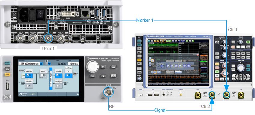
R&S®SMCV100B                                                                                         Contents

     4.8 Connecting a Monitor......................................................................... 20
     4.9 Connecting USB Devices................................................................... 21
   4.10 Connecting to RF 50 Ω....................................................................... 22
   4.11 Connecting to Ref In/Ref Out.............................................................23
   4.12 Connecting to Dig. IQ HS x................................................................ 23
   4.13 Connecting to IP Data Interface.........................................................25
   4.14 Switching On or Off............................................................................ 26

       5 Instrument Tour................................................................... 28
     5.1 Front Panel Tour..................................................................................28
  5.1.1 Touchscreen..........................................................................................29
  5.1.2 Keys...................................................................................................... 30
5.1.2.1 On/Standby........................................................................................... 30
5.1.2.2 Utility Keys............................................................................................ 30
5.1.2.3 Function Keys....................................................................................... 30
5.1.2.4 Editing Keys.......................................................................................... 31
5.1.2.5 Navigation Controls...............................................................................31
           Rotary Knob.......................................................................................... 31
  5.1.3 Connectors............................................................................................32
     5.2 Rear Panel Tour...................................................................................32
  5.2.1 Connectors............................................................................................33

       6 Trying Out the Instrument...................................................36
     6.1 Generating an Unmodulated Carrier................................................. 37
     6.2 Generating a Digitally Modulated Signal.......................................... 39
     6.3 Triggering the Instrument with an External Signal.......................... 41
     6.4 Enabling and Configuring a Marker Signal...................................... 47
     6.5 Verifying the Generated Signal with the Graphics Display............. 48
     6.6 Saving and Recalling Settings...........................................................52

Getting Started 1432.7046.02 ─ 03                                                                                4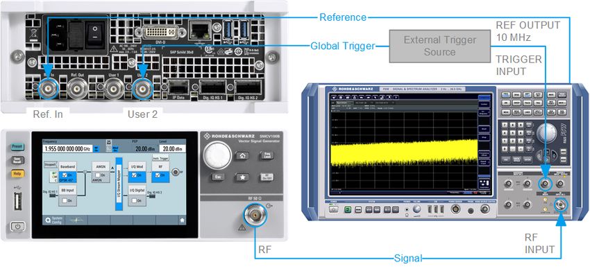
R&S®SMCV100B                                                                                       Contents

    6.7 Generating a DAB Signal................................................................... 55

       7 System Overview................................................................. 58
    7.1 Brief Introduction to the Instrument's Concept............................... 58
    7.2 Signal Flow at a Glance......................................................................58
    7.3 Internal Baseband Source ("Baseband" Block)...............................60
    7.4 Digital Baseband Input/Output ("BB Input"/ "I/Q Digital" Block)... 60
    7.5 Additional White Gaussian Noise ("AWGN" Block)......................... 61
    7.6 "I/Q Stream Mapper" Block................................................................ 61
    7.7 I/Q Modulator ("I/Q Mod" Block)........................................................ 62
    7.8 RF ("RF" Block)...................................................................................62
    7.9 Applications Examples of the R&S SMCV100B............................... 62

       8 Instrument Control.............................................................. 63
    8.1 Possible Ways to Operate the Instrument........................................ 63
    8.2 Means of Manual Interaction..............................................................64
    8.3 Understanding the Display Information............................................64
  8.3.1 Status Bar............................................................................................. 65
  8.3.2 Block Diagram.......................................................................................66
  8.3.3 Taskbar................................................................................................. 67
  8.3.4 Additional Display Characteristics.........................................................68
    8.4 Accessing the Functionality.............................................................. 70
    8.5 Entering Data.......................................................................................71
  8.5.1 Entering Numeric Parameters...............................................................72
  8.5.2 Entering Alphanumeric Parameters...................................................... 73
  8.5.3 Undo and Redo Actions........................................................................ 73
    8.6 Getting Information and Help............................................................ 73
    8.7 Remote Control................................................................................... 75

Getting Started 1432.7046.02 ─ 03                                                                              5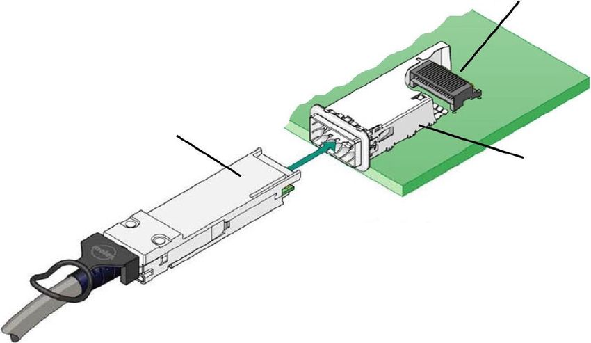
R&S®SMCV100B                                                                            Contents

    8.8 Remote Operation over VNC..............................................................76

      9 Contacting Customer Support........................................... 77

         Index..................................................................................... 78

Getting Started 1432.7046.02 ─ 03                                                                  6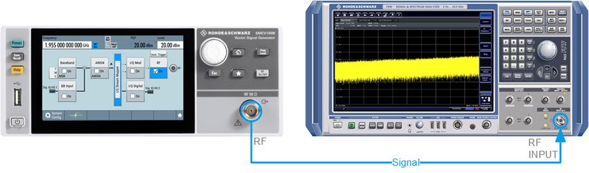
R&S®SMCV100B                                Safety and Regulatory Information
                                                                Safety Instructions

1         Safety and Regulatory Information
The product documentation helps you use the product safely and efficiently. Fol-
low the instructions provided here and in the Chapter 1.1, "Safety Instructions",
on page 7.

Intended use
The product is intended for the development, production and verification of elec-
tronic components and devices in industrial, administrative, and laboratory envi-
ronments. Use the product only for its designated purpose. Observe the operating
conditions and performance limits stated in the data sheet.

Where do I find safety information?
Safety information is part of the product documentation. It warns you of potential
dangers and gives instructions on how to prevent personal injury or damage
caused by dangerous situations. Safety information is provided as follows:
● In Chapter 1.1, "Safety Instructions", on page 7. The same information is
  provided in many languages as printed "Safety Instructions". The printed
  "Safety Instructions" are delivered with the product.
● Throughout the documentation, safety instructions are provided when you
  need to take care during setup or operation.

1.1       Safety Instructions
Products from the Rohde & Schwarz group of companies are manufactured
according to the highest technical standards. To use the products safely, follow
the instructions provided here and in the product documentation. Keep the prod-
uct documentation nearby and offer it to other users.
Use the product only for its intended use and within its performance limits. Inten-
ded use and limits are described in the product documentation such as the data
sheet, manuals and the printed safety instructions. If you are unsure about the
appropriate use, contact Rohde & Schwarz customer service.
Using the product requires specialists or specially trained personnel. These users
also need sound knowledge of at least one of the languages in which the user
interfaces and the product documentation are available.

 Getting Started 1432.7046.02 ─ 03                                                7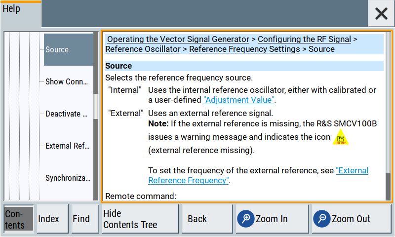
R&S®SMCV100B                                 Safety and Regulatory Information
                                                                 Safety Instructions
If any part of the product is damaged or broken, stop using the product. Never
open the casing of the product. Only service personnel authorized by
Rohde & Schwarz are allowed to repair the product. Contact Rohde & Schwarz
customer service at http://www.customersupport.rohde-schwarz.com.

Lifting and carrying the product
The maximum weight of the product is provided in the data sheet. To move the
product safely, you can use lifting or transporting equipment such as lift trucks
and forklifts. Follow the instructions provided by the equipment manufacturer.

Choosing the operating site
Only use the product indoors. The product casing is not waterproof. Water that
enters can electrically connect the casing with live parts, which can lead to elec-
tric shock, serious personal injury or death if you touch the casing. If
Rohde & Schwarz provides a carrying bag designed for your product, you can
use the product outdoors.
Unless otherwise specified, you can operate the product up to an altitude of
2000 m above sea level. The product is suitable for pollution degree 2 environ-
ments where nonconductive contamination can occur. For more information on
environmental conditions such as ambient temperature and humidity, see the
data sheet.

Setting up the product
Always place the product on a stable, flat and level surface with the bottom of the
product facing down. If the product is designed for different positions, secure the
product so that it cannot fall over.
If the product has foldable feet, always fold the feet completely in or out to ensure
stability. The feet can collapse if they are not folded out completely or if the prod-
uct is moved without lifting it. The foldable feet are designed to carry the weight of
the product, but not an extra load.
If stacking is possible, keep in mind that a stack of products can fall over and
cause injury.
If you mount products in a rack, ensure that the rack has sufficient load capacity
and stability. Observe the specifications of the rack manufacturer. Always install
the products from the bottom shelf to the top shelf so that the rack stands
securely. Secure the product so that it cannot fall off the rack.

 Getting Started 1432.7046.02 ─ 03                                                  8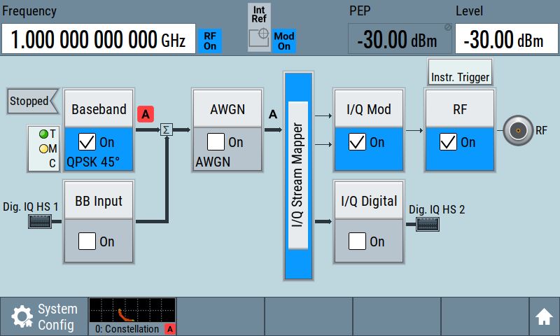
R&S®SMCV100B                                Safety and Regulatory Information
                                                               Safety Instructions
Connecting to power
The product is an overvoltage category II product and has to be connected to a
fixed installation used to supply energy-consuming equipment such as household
appliances and similar loads. Be aware that electrically powered products have
risks, such as electric shock, fire, personal injury or even death.
Take the following measures for your safety:
● Before switching on the product, ensure that the voltage and frequency indica-
  ted on the product match the available power source. If the power adapter
  does not adjust automatically, set the correct value and check the rating of the
  fuse.
● If a product has an exchangeable fuse, its type and characteristics are indica-
  ted next to the fuse holder. Before changing the fuse, switch off the instrument
  and disconnect it from the power source. How to change the fuse is described
  in the product documentation.
● Only use the power cable delivered with the product. It complies with country-
  specific safety requirements. Only insert the plug into an outlet with protective
  conductor terminal.
● Only use intact cables and route them carefully so that they cannot be dam-
  aged. Check the power cables regularly to ensure that they are undamaged.
  Also ensure that nobody can trip over loose cables.
● If the product needs an external power supply, use the power supply that is
  delivered with the product or that is recommended in the product documenta-
  tion or a power supply that conforms to the country-specific regulations.
● Only connect the product to a power source with a fuse protection of maxi-
  mum 20 A.
● Ensure that you can disconnect the product from the power source at any
  time. Pull the power plug to disconnect the product. The power plug must be
  easily accessible. If the product is integrated into a system that does not meet
  these requirements, provide an easily accessible circuit breaker at the system
  level.

Cleaning the product
Use a dry, lint-free cloth to clean the product. When cleaning, keep in mind that
the casing is not waterproof. Do not use liquid cleaning agents.

Meaning of safety labels
Safety labels on the product warn against potential hazards.

 Getting Started 1432.7046.02 ─ 03                                                  9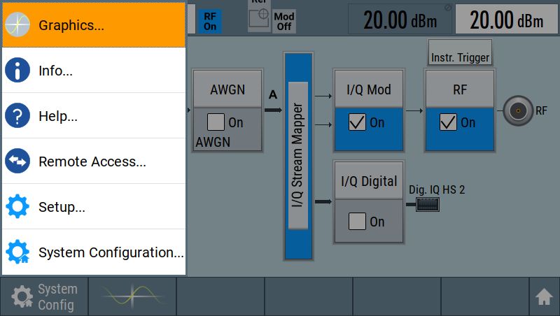
R&S®SMCV100B                                        Safety and Regulatory Information
                                                                 Korea Certification Class B

        Potential hazard
        Read the product documentation to avoid personal injury or product damage.

        Electrical hazard
        Indicates live parts. Risk of electric shock, fire, personal injury or even death.

        Hot surface
        Do not touch. Risk of skin burns. Risk of fire.

        Protective conductor terminal
        Connect this terminal to a grounded external conductor or to protective ground. This
        protects you against electric shock should an electric problem occur.

1.2       Labels on R&S SMCV100B
Labels on the casing inform about:
● Personal safety, see "Connecting to power" on page 9.
● Product and environment safety, see Table 1-1.
● Identification of the product, see the serial number on the rear panel.
Table 1-1: Labels regarding R&S SMCV100B and environment safety
       Labeling in line with EN 50419 for disposal of electrical and electronic equipment after
       the product has come to the end of its service life. For more information, see the prod-
       uct user manual, chapter "Disposal".

1.3       Korea Certification Class B

이 기기는 가정용(B급) 전자파 적합기기로서 주로 가정에서 사용하는 것을 목적으
로 하며, 모든 지역에서 사용할 수 있습니다.

 Getting Started 1432.7046.02 ─ 03                                                           10
R&S®SMCV100B Documentation Overview
User Manuals and Help
2 Documentation Overview
This section provides an overview of the R&S SMCV100B user documentation.
Unless specified otherwise, you find the documents on the R&S SMCV100B
product page at:
www.rohde-schwarz.com/manual/smcv100b
2.1 Getting Started Manual
Introduces the R&S SMCV100B and describes how to set up and start working
with the product. Includes basic operations, typical measurement examples, and
general information, e.g. safety instructions, etc. A printed version is delivered
with the instrument.
2.2 User Manuals and Help
Separate manuals for the base unit and the software options are provided for
download:
● Base unit manual
Contains the description of all instrument modes and functions. It also pro-
vides an introduction to remote control, a complete description of the remote
control commands with programming examples, and information on mainte-
nance, instrument interfaces and error messages. Includes the contents of the
getting started manual.
● Software option manual
Contains the description of the specific functions of an option. Basic informa-
tion on operating the R&S SMCV100B is not included.
The contents of the user manuals are available as help in the R&S SMCV100B.
The help offers quick, context-sensitive access to the complete information for the
base unit and the software options.
All user manuals are also available for download or for immediate display on the
Internet.
Getting Started 1432.7046.02 ─ 03 11R&S®SMCV100B Documentation Overview
Data Sheets and Brochures
2.3 Service Manual
Describes the performance test for checking compliance with rated specifications,
firmware update, troubleshooting, adjustments, installing options and mainte-
nance.
The service manual is available for registered users on the global
Rohde & Schwarz information system (GLORIS):
https://gloris.rohde-schwarz.com
2.4 Instrument Security Procedures
Deals with security issues when working with the R&S SMCV100B in secure
areas. It is available for download on the Internet.
2.5 Printed Safety Instructions
Provides safety information in many languages. The printed document is deliv-
ered with the product.
2.6 Data Sheets and Brochures
The data sheet contains the technical specifications of the R&S SMCV100B. It
also lists the options and their order numbers and optional accessories.
The brochure provides an overview of the instrument and deals with the specific
characteristics.
See www.rohde-schwarz.com/brochure-datasheet/smcv100b
Getting Started 1432.7046.02 ─ 03 12R&S®SMCV100B Documentation Overview
Application Notes, Application Cards, White Papers, etc.
2.7 Release Notes and Open Source Acknowledg-
ment (OSA)
The release notes list new features, improvements and known issues of the cur-
rent firmware version, and describe the firmware installation.
The open-source acknowledgment document provides verbatim license texts of
the used open source software.
See www.rohde-schwarz.com/firmware/smcv100b
2.8 Application Notes, Application Cards, White
Papers, etc.
These documents deal with special applications or background information on
particular topics.
See www.rohde-schwarz.com/application/smcv100b
Getting Started 1432.7046.02 ─ 03 13R&S®SMCV100B Key Features 3 Key Features The R&S SMCV100B is a new signal generator in the economy range developed to meet demanding customer requirements. Offering excellent signal characteris- tic and straightforward and intuitive operation, the signal generator makes signal generation fast and easy. Outstanding key features of the R&S SMCV100B are: ● First multi-standard platform for broadcast, navigation, cellular and wireless applications ● Fully software defined vector signal generator ● Modern RF signal generation concept from 8 kHz to 7.125 GHz ● High RF output power of up to 25 dBm ● Modulation bandwidth up to 240 MHz with internal baseband ● Powerful internal baseband generator with internal broadcast real-time coder, Custom Digital Modulation and internal baseband signal generation with ARB ● Support of terrestrial, satellite and audio broadcast standards such as ATSC 3.0, ATSC-M/H, DTMB, DVB-T2, DVB-T, ISDB-T, ISDB-TSB, T-DMB/DAB, DVB-S2, DVB-S, DRM/DRM+, Audio AM/FM, RDS/RDBS/DARC ● Support of digital standard waveforms such as 5G NR, LTE including eMTC/NB-IoT, WLAN IEEE 802.11a/b/g/n/j/p/ac/ax ● Intuitive operation via 5'' touchscreen with block diagram as key element ● Graphical signal monitoring at practically every point in the signal flow ● SCPI macro recorder and code generator for generating executable remote control code from manual operating steps (for MATLAB®, CVI, etc.) ● Easily extendable with software options ● Full remote compatibility with R&S SFE/R&S SFE100 For more information, see data sheet. Getting Started 1432.7046.02 ─ 03 14
R&S®SMCV100B                                                   Preparing for Use
                                                      Choosing the Operating Site

4         Preparing for Use
Here, you can find basic information about setting up the instrument for the first
time.

4.1       Lifting and Carrying
See also "Lifting and carrying the product" on page 8.
For mounting the R&S SMCV100B in a rack, see Chapter 4.4.2, "Mounting the
R&S SMCV100B in a Rack", on page 17.

4.2       Unpacking and Checking

1. Unpack the R&S SMCV100B carefully.
2. Retain the original packing material. Use it to protect the control elements and
   connectors when transporting or shipping the R&S SMCV100B later.
   See also chapter "Transporting" in the user manual.
3. Using the delivery notes, check the equipment for completeness.
4. Check the equipment for damage.
    If the delivery is incomplete or equipment is damaged, contact
    Rohde & Schwarz.

4.3       Choosing the Operating Site
Specific operating conditions ensure proper operation and avoid damage to the
product and connected devices. For information on environmental conditions
such as ambient temperature and humidity, see the data sheet.
See also "Choosing the operating site" on page 8.

 Getting Started 1432.7046.02 ─ 03                                               15
R&S®SMCV100B Preparing for Use
Setting Up the R&S SMCV100B
Electromagnetic compatibility classes
The electromagnetic compatibility (EMC) class indicates where you can operate
the product. The EMC class of the product is given in the data sheet under "Gen-
eral data".
● Class B equipment is suitable for use in:
– Residential environments
– Environments that are directly connected to a low-voltage supply network
that supplies residential buildings
● Class A equipment is intended for use in industrial environments. It can cause
radio disturbances in residential environments due to possible conducted and
radiated disturbances. It is therefore not suitable for class B environments.
If class A equipment causes radio disturbances, take appropriate measures to
eliminate them.
4.4 Setting Up the R&S SMCV100B
See also:
● "Setting up the product" on page 8.
● "Intended use" on page 7.
4.4.1 Placing the R&S SMCV100B on a Bench Top
To place the product on a bench top
1. Place the product on a stable, flat and level surface. Ensure that the surface
can support the weight of the product. For information on the weight, see the
data sheet.
2. CAUTION! Foldable feet can collapse. See "Setting up the product"
on page 8.
Always fold the feet completely in or out. With folded-out feet, do not place
anything on top or underneath the product.
3. WARNING! A stack of products can fall over and cause injury. Never stack
more than three products on top of each other. Instead, mount them in a rack.
Stack as follows:
Getting Started 1432.7046.02 ─ 03 16R&S®SMCV100B Preparing for Use
Setting Up the R&S SMCV100B
● If the products have foldable feet, fold them in completely.
● All products must have the same dimensions (width and length).
● Do not exceed a total load of 50 kg placed on the product at the bottom of
the stack.
Left = Stacked correctly
Middle left = Stacked incorrectly, too many products
Middle right = Stacked incorrectly, different dimensions
Right = Stacked incorrectly, different dimensions, folded-out feet
4. NOTICE! Overheating can damage the product.
Prevent overheating as follows:
● Keep a minimum distance of 10 cm between the fan openings of the prod-
uct and any object in the vicinity.
● Do not place the product next to heat-generating equipment such as radia-
tors or other products.
4.4.2 Mounting the R&S SMCV100B in a Rack
To prepare the rack
1. Observe the requirements and instructions in "Setting up the product"
on page 8.
2. NOTICE! Insufficient airflow can cause overheating and damage the product.
Design and implement an efficient ventilation concept for the rack.
To mount the R&S SMCV100B in a rack
1. Use an adapter kit that fits the dimensions of the R&S SMCV100B to prepare
the instrument for rack mounting. For information on the dimensions, see data
sheet.
a) Order the rack adapter kit designed for the R&S SMCV100B. For the order
number, see data sheet.
Getting Started 1432.7046.02 ─ 03 17R&S®SMCV100B Preparing for Use
Important Aspects for Test Setup
b) Mount the adapter kit. Follow the assembly instructions provided with the
adapter kit.
2. Lift the R&S SMCV100B to shelf height.
3. Push the R&S SMCV100B onto the shelf until the rack brackets fit closely to
the rack.
4. Tighten all screws at the rack brackets with a tightening torque of 1.2 Nm to
secure the R&S SMCV100B at the rack.
To unmount the R&S SMCV100B from a rack
1. Loosen the screws at the rack brackets.
2. Bring the lifting equipment to shelf height.
3. Remove the R&S SMCV100B from the rack.
4. If placing the R&S SMCV100B on a bench top again, unmount the adapter kit
from the R&S SMCV100B. Follow the instructions provided with the adapter
kit.
4.5 Important Aspects for Test Setup
Cable selection and electromagnetic interference (EMI)
Electromagnetic interference (EMI) can affect the measurement results.
To suppress electromagnetic radiation during operation:
● Use high-quality shielded cables, especially for the following connector types:
– BNC
Double-shielded BNC cables.
– USB
Double-shielded USB cables.
How to: Chapter 4.9, "Connecting USB Devices", on page 21.
See also chapter "Troubleshooting and Error Messages" in the user man-
ual.
– LAN
At least CAT6 STP cables.
How to: Chapter 4.7, "Connecting to LAN", on page 19
Getting Started 1432.7046.02 ─ 03 18R&S®SMCV100B Preparing for Use
Connecting to LAN
● Always terminate open cable ends.
● Ensure that connected external devices comply with EMC regulations.
● Use the cable R&S DIGIQ-HS for connection to the "Dig. IQ HS x" interfaces
of the instrument. The cable is available under material number 3641.2948.03.
How to: Chapter 4.12, "Connecting to Dig. IQ HS x", on page 23
● Use an SFP+ to RJ-45 adapter and an RJ-45 cable for connection to the "IP
Data" interface of the instrument. We recommend that you use the adapter
"FCLF850P2BTL" from Finisar available under material number
3627.0570.00.
How to: Chapter 4.13, "Connecting to IP Data Interface", on page 25
Signal input and output levels
Information on signal levels is provided in the data sheet. Keep the signal levels
within the specified ranges to avoid damage to the R&S SMCV100B and connec-
ted devices.
4.6 Connecting to Power
For safety information, see "Connecting to power" on page 9.
1. Plug the AC power cable into the AC power connector on the rear panel of the
instrument. Only use the AC power cable delivered with the R&S SMCV100B.
2. Plug the AC power cable into a power outlet with ground contact.
The required ratings are listed next to the AC power connector and in the data
sheet.
4.7 Connecting to LAN
Network environment
Before connecting the product to a local area network (LAN), consider the follow-
ing:
● Install the latest firmware to reduce security risks.
● For internet or remote access, use secured connections if applicable.
Getting Started 1432.7046.02 ─ 03 19R&S®SMCV100B Preparing for Use
Connecting a Monitor
● Ensure that the network settings comply with the security policies of your com-
pany. Contact your local system administrator or IT department before con-
necting your product to your company LAN.
● When connected to the LAN, the product may potentially be accessed from
the internet, which may be a security risk. For example, attackers might mis-
use or damage the product.
To connect to LAN
The connector is located on the rear panel.
► Connect the LAN socket via an RJ-45 cable to the LAN.
By default, the R&S SMCV100B is configured to use DHCP (dynamic host config-
uration protocol) and no static IP address is configured.
If switched on and connected to the LAN, the R&S SMCV100B displays the
address information on the screen.
Figure 4-1: IP address indication on the screen (example)
See also the chapter "Connecting the Instrument to the Network (LAN)" in the
user manual.
4.8 Connecting a Monitor
This section describes how to connect a monitor for direct operation of the
R&S SMCV100B. You can skip the following procedure, if you only operate the
R&S SMCV100B remotely.
The connector is located on the rear panel.
► Connect the monitor to the "DVI-D" socket.
You can connect the following types of monitor sockets:
● DVI-D: Connect it to the "DVI-D" socket.
DVI-A: not supported
DVI-I: not supported
Getting Started 1432.7046.02 ─ 03 20R&S®SMCV100B Preparing for Use
Connecting USB Devices
● HDMI: You need an adapter. Use a passive DVI to HDMI adapter.
● VGA: You need an active adapter, DVI to VGA or Display Port to VGA.
Passive adapters do not work.
If the monitor provides touch functionality, an additional connection can be
required, for example, a USB connection. Refer to the documentation of your
monitor.
4.9 Connecting USB Devices
USB connectors are located on the front panel and rear panel. You can connect
or disconnect all USB devices from the R&S SMCV100B during operation.
To connect USB storage devices
USB storage devices, such as memory sticks, allow easy data transfer from/to the
R&S SMCV100B. You can also use them for firmware updates.
► Connect the USB storage device to any of the USB connectors.
To connect USB devices with external power supply
1. NOTICE! Connected devices with external power supply can feed back cur-
rent into the 5 V power supply of the USB interface and thus damage the
R&S SMCV100B.
Ensure that there is no connection between the positive pole of the power
supply and the +5 V power pin of the USB interface (VBUS).
2. Connect the USB storage device to any of the USB connectors.
To connect a keyboard
► Connect the keyboard to any of the USB connectors.
When connected, the R&S SMCV100B detects the keyboard automatically. A
detected keyboard has the default layout English – US.
To connect a mouse
► Connect the mouse to any of the USB connectors.
Getting Started 1432.7046.02 ─ 03 21R&S®SMCV100B Preparing for Use
Connecting to RF 50 Ω
When connected, the R&S SMCV100B detects the mouse automatically.
To connect power sensors
You can connect power sensors of the R&S NRP families to any of the USB con-
nectors.
See chapter "Using Power Sensors" in the user manual.
4.10 Connecting to RF 50 Ω
The connector is located on the front panel.
To prepare for connecting to RF 50 Ω
1. NOTICE! Damaged or not clean connections can lead to RF insertion loss
and mismatch, and even premature wear of the connectors.
Before connecting to the port, inspect the RF connector visually to check that
it is clean, undamaged and mechanically compatible.
See the application note 1MA99 for information on how to handle and main-
tain the RF port, to minimize measurement deviations and ensure its longevity.
2. NOTICE! Risk of instrument damage. Excessive reverse power or DC voltage
at the "RF 50 Ω" connector can damage the instrument.
Make sure that the values do not exceed the reverse power and DC limits as
given in the data sheet.
3. If the R&S SMCV100B is switched on, deactivate the RF output, before con-
necting an RF cable to the "RF 50 Ω" connector.
In the block diagram, select the block "RF" > "RF Level" > "RF ON > Off".
4. Use a high-quality RF cable that matches the RF connector type.
See "Cable selection and electromagnetic interference (EMI)" on page 18.
To connect to non-screwable connectors (BNC)
► To connect the RF cable with the "RF 50 Ω" connector, proceed as follows:
a) Carefully align the connector of the cable and the "RF 50 Ω" connector
along a common axis.
Getting Started 1432.7046.02 ─ 03 22R&S®SMCV100B Preparing for Use
Connecting to Dig. IQ HS x
b) Mate the connectors along the common axis until the male pin of the con-
nector of the cable engages with the female socket of the "RF 50 Ω" con-
nector.
The connector types listed in this table represent the common connectors provi-
ded by Rohde & Schwarz. It is considered as general information and therefore
can contain connector types that do not apply to your instrument.
See "RF 50 Ω" on page 32.
To prevent RF output switch-off
► NOTICE! If you set a too high output level without a load connected to the
instrument, the reverse power can exceed a limit forcing the R&S SMCV100B
to switch off the RF output.
Connect a load with sufficient return loss as given in the data sheet.
4.11 Connecting to Ref In/Ref Out
The connector is located on the rear panel.
To connect to Ref In/Ref Out (reference < 1 GHz)
For connection, the R&S SMCV100B provides BNC connectors.
► Follow the instructions in "To connect to non-screwable connectors (BNC)"
on page 22.
4.12 Connecting to Dig. IQ HS x
The "Dig. IQ HS x" connector comprises a QSFP+ (Quad Small Form-factor Plug-
gable) socket, that has two components: a QSFP+ cage and a QSFP+ connector.
The QSFP+ cable is equipped with the QSFP+ plug.
Getting Started 1432.7046.02 ─ 03 23R&S®SMCV100B Preparing for Use
Connecting to Dig. IQ HS x
3
1
2
1 = QSFP+ plug
2 = QSFP+ cage
3 = QSFP+ connector
The connector is located on the rear panel.
To connect to Dig. IQ HS x interface
1. For connection, use the QSFP+ cable R&S DIGIQ-HS.
See "Cable selection and electromagnetic interference (EMI)" on page 18.
2. Hold the QSFP+ plug of the cable by its panes.
3. Turn the QSFP+ cable, so that the release tab shows upwards.
4. Insert and push the QSFP+ plug into the QSFP+ cage.
To disconnect from Dig. IQ HS x interface
1. NOTICE! If you pull the cable, you can damage the cable and the "Dig. IQ HS
x" connector.
Pull the release tab.
2. Pull the QSFP+ plug out of the QSFP+ cage.
See also chapters "Digital Baseband Input Settings" and "I/Q Digital Output Set-
tings" in the user manual.
Getting Started 1432.7046.02 ─ 03 24R&S®SMCV100B Preparing for Use
Connecting to IP Data Interface
4.13 Connecting to IP Data Interface
The "IP Data" connector comprises an SFP+ (Small Form-factor Pluggable)
socket, that has two components an SFP+ cage and an SFP+ connector.
1
2
1 = SFP+ cage
2 = SFP+ connector
The connector is located on the rear panel.
To connect to IP Data interface
1. For connection, use an SFP+ to RJ-45 adapter and an RJ-45 cable.
See "Cable selection and electromagnetic interference (EMI)" on page 18.
4
3
2
2
1
3a
Figure 4-2: Connecting to the IP Data interface
1 = RJ-45 cable and plug
2 = Axis of connection
3 = SFP+ to RJ-45 adapter
3a = Bracket for mounting and releasing the adapter
4 = SFP+ socket of the "IP Data" connector
2. Connect the SFP+ to RJ-45 adapter to the SFP+ socket of the "IP Data" con-
nector first (Figure 4-2).
a) Turn the adapter, so that the release bracket joints show upwards.
b) At the RJ-45 socket of the adapter, open the release bracket, so that the
bracket shows upward.
Getting Started 1432.7046.02 ─ 03 25R&S®SMCV100B Preparing for Use
Switching On or Off
c) Insert and push the adapter into the cage of the SFP+ socket of the "IP
Data" connector.
d) To mount the adapter, push the release bracket down to close the bracket.
The adapter is connected to the "IP Data" connector.
3. Plug the RJ-45 cable into the RJ-45 socket of the adapter.
To disconnect from IP Data interface
1. Unplug the RJ-45 cable.
2. Open the release bracket.
3. Carefully pull the SFP+ to RJ-45 adapter out of the SFP+ socket of the "IP
Data" interface.
Use the "IP Data" interface as input of external coding IP data for broadcast base-
band signals.
See also chapter "Local IP Data Network Settings" in the corresponding broad-
cast standard user manuals.
4.14 Switching On or Off
The following table provides an overview of power states, LEDs and power switch
positions.
Table 4-1: Overview of power states
State LED Position of power switch
Off gray [0]
Standby orange [I]
Ready green [I]
To switch on the R&S SMCV100B
The R&S SMCV100B is off but connected to power. See Chapter 4.6, "Connect-
ing to Power", on page 19.
1. Set the switch on the power supply to position [I].
The switch is located on the rear panel.
The LED of the [On/Standby] key is orange.
Getting Started 1432.7046.02 ─ 03 26R&S®SMCV100B Preparing for Use
Switching On or Off
2. Wait until the oven-controlled oscillator (OCXO) warms up. For the warm-up
time, see data sheet.
3. Press the [On/Standby] key.
Key and LED are located on the front panel.
The LED changes to green. The R&S SMCV100B boots.
When starting for the first time, the R&S SMCV100B starts with the default
settings. When restarting the instrument, the settings depend on the instru-
ment configuration before shut-down.
See the chapter "Saving and Recalling Instrument Settings" in the user man-
ual.
When the instrument is switched on, it automatically monitors main functions. You
can query erroneous functions. In addition to automatic monitoring, you can per-
form maintenance tasks.
See:
● Chapter "Querying Error Messages" in the user manual.
● Chapter "Performing Maintenance Tasks" in the user manual.
To shut down the product
The product is in the ready state.
► Press the [On/Standby] key.
The operating system shuts down. The LED changes to orange.
In the standby state, the power switch circuits and the OCXO are active. To deac-
tivate them, disconnect the instrument from the power supply.
To disconnect from power
The R&S SMCV100B is in the standby state.
1. NOTICE! Risk of data loss. If you disconnect the product from power when it
is in the ready state, you can lose settings and data. Shut it down first.
Set the toggle switch on the power supply to position [0].
The LED of the [On/Standby] key is switched off.
2. Disconnect the R&S SMCV100B from the power source.
Getting Started 1432.7046.02 ─ 03 27R&S®SMCV100B Instrument Tour
Front Panel Tour
5 Instrument Tour
The following topics help you get familiar with the instrument and perform the first
steps:
● Front Panel Tour
● Rear Panel Tour
This section explains the control elements and the connectors of the
R&S SMCV100B with the aid of the front and rear views. For specifications of the
interfaces, refer to the data sheet.
The meanings of the labels on the R&S SMCV100B are described in Chapter 1.2,
"Labels on R&S SMCV100B", on page 10.
5.1 Front Panel Tour
This section provides an overview of the control elements and connectors of the
front panel of the R&S SMCV100B. On the rear panel, you find all further connec-
tors of the unit.
4 5
3
6
2
7
1
Figure 5-1: Front panel view
1 = [On/Standby], see Chapter 5.1.2.1, "On/Standby", on page 30
2 = "USB" connector, see "USB" on page 32
3 = Utility keys, see Chapter 5.1.2.2, "Utility Keys", on page 30
4 = Touchscreen, see Chapter 5.1.1, "Touchscreen", on page 29
Getting Started 1432.7046.02 ─ 03 28R&S®SMCV100B Instrument Tour
Front Panel Tour
5 = Rotary knob, see "Rotary Knob" on page 31
6 = Function keys and editing keys, see Chapter 5.1.2.3, "Function Keys", on page 30 and
Chapter 5.1.2.4, "Editing Keys", on page 31
7 = "RF 50 Ω" output connector, see Chapter 5.1.3, "Connectors", on page 32
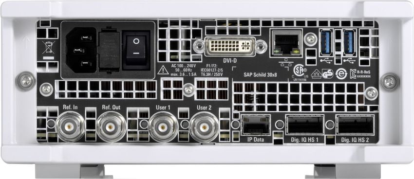
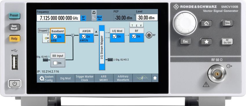
5.1.1 Touchscreen
The block diagram and the most important settings are displayed on the screen
on the front panel. Also, the screen display provides status and setting informa-
tion and allows you to quickly reconfigure the signal flow. The screen is touch-
sensitive, offering an alternative means of user interaction for quick and easy
handling of the instrument.
1
2
3
Figure 5-2: Touchscreen elements
1 = Status bar (frequency and level display)
2 = Block diagram
3 = Taskbar/softkey bar
Any user interface elements that react to a click by a mouse pointer also react to
a tap on the screen, and vice versa. Using the touchscreen, you can perform the
following tasks (among others) by the tap of your finger:
● Changing a setting
● Selecting new settings
● Scrolling through a list or a table of parameters
● Saving or recalling settings
Getting Started 1432.7046.02 ─ 03 29R&S®SMCV100B Instrument Tour
Front Panel Tour
● Opening and closing dialogs
See also:
● Chapter 8.2, "Means of Manual Interaction", on page 64, for operating the
touchscreen.
● "Maintenance" in the user manual, for instructions on cleaning the screen.
5.1.2 Keys
5.1.2.1 On/Standby
The [On/Standby] key switches the instrument from the standby to the ready state
or vice versa.
The LED below the [On/Standby] key indicates the instrument state, see Chap-
ter 4.14, "Switching On or Off", on page 26.
5.1.2.2 Utility Keys
The utility keys cause the R&S SMCV100B to return to a defined instrument state
and provide information on the instrument and assistance.
For more information, refer to chapter "General Instrument Functions" in the user
manual.
Table 5-1: Utility keys
Utility key Assigned functions
[Preset] Sets the instrument to a defined state
[Save/Rcl] Saves and loads instrument setting
Accesses the file manager
[Help] Displays context-sensitive help text
5.1.2.3 Function Keys
Function keys provide access to most common generator settings and functions.
A detailed description of the corresponding functions is provided in the user man-
ual.
Getting Started 1432.7046.02 ─ 03 30R&S®SMCV100B Instrument Tour
Front Panel Tour
Table 5-2: Function keys
Function key Assigned functions
[Freq/Level] Pressing once: Activates frequency entry. Pressing twice: Acti-
vates level entry.
Toggles between frequency and level entry.
[Home] Brings the block diagram to the foreground. Active dialogs are
minimized.
[RF on/off] Switches the RF output on and off. Press the key again to restore
the last active status.
Status is displayed in the "Status bar".
[★ (User)] Key with a customizable function.
5.1.2.4 Editing Keys
Editing keys enable you to confirm an entry, delete individual characters, or exit
the current operation.
Table 5-3: Editing keys
Type of key Description
[Esc] key Closes all kinds of dialog boxes, if the edit mode is not active.
Quits the edit mode, if the edit mode is active. In dialog boxes
that contain a "Cancel" button it activates that button.
For "Edit" dialog boxes the following mechanism is used:
● If data entry has been started, it retains the original value
and closes the dialog box.
● If data entry has not been started or has been completed, it
closes the dialog box.
5.1.2.5 Navigation Controls
The navigation controls include a rotary knob, navigation keys, and the display
keys. They allow you to navigate within the display or within dialog boxes.
Rotary Knob
The rotary knob has several functions:
● Increments (clockwise direction) or decrements (counterclockwise direction)
numeric instrument parameters at a defined step width.
● Moves the selection, e.g. to a function block in the block diagram.
Getting Started 1432.7046.02 ─ 03 31R&S®SMCV100B Instrument Tour
Rear Panel Tour
● Shifts the selection bar within focused areas (e.g. lists).
● Activates editing of entries or confirms and terminates entries.
● Opens a context-sensitive menu, when it is pressed and held.
5.1.3 Connectors
The "RF 50 Ω" connector and "USB" connector are on the front panel.
USB
There is one female USB (universal serial bus) 2.0 connector of type A (host
USB) on the front panel. You can connect, for example, a keyboard, a mouse or a
USB memory stick.
Further "USB" connectors of type A are available on the rear panel.
How to: Chapter 4.9, "Connecting USB Devices", on page 21.
RF 50 Ω
Output of the RF signal (N female connector).
How to: Chapter 4.10, "Connecting to RF 50 Ω", on page 22
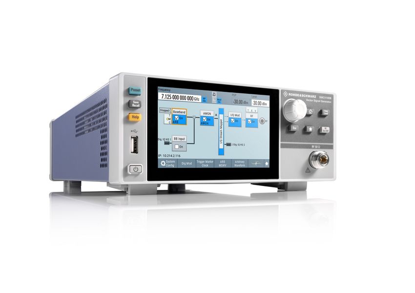
5.2 Rear Panel Tour
This section provides an overview of the connectors on the rear panel of the
instrument. For technical data of the connectors, refer to the data sheet.
Getting Started 1432.7046.02 ─ 03 32R&S®SMCV100B Instrument Tour
Rear Panel Tour
1 2 3 4 5
9 8 7 6
Figure 5-3: Rear panel
1 = AC power supply connection and main power switch, see "AC power supply connector and
switch" on page 33
2 = "DVI-D" connector (output), see "DVI-D" on page 33
3 = Serial number (six digits in the string 1432.7000.02--)
4 = "LAN" connector, see "LAN" on page 34
5 = "USB" connectors, see "USB" on page 34
6 = "Dig. IQ HS x" connector, see "Dig. IQ HS x" on page 34
7 = "IP Data" connector, see "IP Data" on page 34
8 = "User x" connectors, "User x" on page 34
9 = "Ref In"/"Ref Out" connectors, see "Ref In/Ref Out" on page 35
5.2.1 Connectors
AC power supply connector and switch
Mains power switch for performing the following tasks:
● Connecting the internal power supply to the power source
● Disconnecting the internal power supply from the power source
How to: Chapter 4.6, "Connecting to Power", on page 19.
DVI-D
DVI-D socket. Output for the monitor signal of the built-in computer. The connec-
ted computer monitor should provide a resolution of 1024x768 pixels or higher.
How to: Chapter 4.8, "Connecting a Monitor", on page 20
Getting Started 1432.7046.02 ─ 03 33R&S®SMCV100B Instrument Tour
Rear Panel Tour
LAN
RJ-45 connector to connect the R&S SMCV100B to a LAN for remote control,
remote operation, and data transfer.
How to: Chapter 4.7, "Connecting to LAN", on page 19
USB
There are two female USB (universal serial bus) 3.0 connectors of type A (host
USB) on the rear panel. They have the same functionality as the USB connectors
on the front panel, but provide higher data rates. See "USB" on page 32.
How to: Chapter 4.9, "Connecting USB Devices", on page 21.
Dig. IQ HS x
Connectors for the input/output of high-speed digital I/Q signals, for example,
from and to Rohde & Schwarz instruments.
Table 5-4 lists the interface designation (input/output) and the required option.
For more information, see data sheet.
Table 5-4: Overview of Dig. IQ HS x interfaces and required options
Interface Designation Required option
"Dig. IQ HS 1" "BB Input" R&S SMCVB-K19 digital baseband interface
"Dig. IQ HS 2" "I/Q Digital Out"
The interface is a QSFP+ (Quad Small Form-factor Pluggable) module. It sup-
ports max. bandwidth of up to 50 Gsample/s with optical active cables.
How to: Chapter 4.12, "Connecting to Dig. IQ HS x", on page 23
IP Data
Interface for input of IP data for real-time encoding in broadcast baseband sig-
nals.
The interface comprises a SFP+ (Small Form-factor Pluggable) socket.
How to: Chapter 4.13, "Connecting to IP Data Interface", on page 25
User x
BNC multipurpose connectors for defining input signals and output signals.
Table 5-5 lists the signals assigned to the "User x" connectors in the default
instrument state.
Getting Started 1432.7046.02 ─ 03 34R&S®SMCV100B Instrument Tour
Rear Panel Tour
Table 5-5: Default configuration of the User x connectors
"User" connector Direction Default assigned signal
1 Output Baseband Marker 1
2 Input Global Clock
A dedicated LED indicates the connector status:
● green: an input connector
● yellow: an output connector
● red: error
● no light / gray: the connector is not active
● blinking LED: connection indication as result of the "Identify Connector"
function
See also chapter "Global Connector Settings" in the user manual.
Ref In/Ref Out
Input/output for external reference signal.
BNC connectors for reference signals from 1 MHz to 100 MHz.
How to: Chapter 4.11, "Connecting to Ref In/Ref Out", on page 23
Getting Started 1432.7046.02 ─ 03 35R&S®SMCV100B Trying Out the Instrument
6 Trying Out the Instrument
This chapter introduces the most important functions and settings of the
R&S SMCV100B step by step.
The complete description of the functionality and its usage is given in the
R&S SMCV100B user manual. Basic instrument operation is described in Chap-
ter 8, "Instrument Control", on page 63.
Prerequisites
● R&S SMCV100B equipped with its minimum configuration:
– Base unit
– Frequency option R&S SMCVB-B103
● The R&S SMCV100B is connected to the power supply, and started up as
described in Chapter 4, "Preparing for Use", on page 15.
For the first signal generation tasks, you use the internal baseband and reference
signal, so you do not need any additional signal source. More complex signal
generation tasks, however, require an instrument equipped with additional options
and/or external signals. Each task description lists its prerequisites.
The screenshots in this description show a fully equipped instrument. Con-
sider that, the block diagram displayed on your particular instrument can dif-
fer from the one used in the example.
Touchscreen operation
For detailed information on touchscreen operation, see Chapter 8.2, "Means of
Manual Interaction", on page 64.
The following sections provide introductory operation examples using the touch-
screen.
● Generating an Unmodulated Carrier............................................................... 37
● Generating a Digitally Modulated Signal......................................................... 39
● Triggering the Instrument with an External Signal...........................................41
● Enabling and Configuring a Marker Signal......................................................47
● Verifying the Generated Signal with the Graphics Display..............................48
● Saving and Recalling Settings........................................................................ 52
● Generating a DAB Signal................................................................................ 55
Getting Started 1432.7046.02 ─ 03 36R&S®SMCV100B Trying Out the Instrument
Generating an Unmodulated Carrier
6.1 Generating an Unmodulated Carrier
We start out by generating a simple unmodulated signal. The R&S SMCV100B
has a minimum configuration as in "Prerequisites" on page 36.
1. On the R&S SMCV100B front panel, press the Preset key to start out in a
defined instrument configuration.
2. Set the frequency:
a) On the "Status Bar", tap the "Frequency" field.
b) On the on-screen keypad, enter 1.955 and press the "GHz" key.
The on-screen keypad closes and the frequency value is displayed.
3. On the "Status Bar", tap the "Level" field and enter the level in the same way.
4. Select "Block Diagram > RF Block > On" to enable the output of the generated
unmodulated signal.
Getting Started 1432.7046.02 ─ 03 37R&S®SMCV100B Trying Out the Instrument
Generating an Unmodulated Carrier
Figure 6-1: Block diagram: Generating an unmodulated signal
The 1.955 GHz signal is output at the "RF 50 Ω" connector at the front panel
of the R&S SMCV100B.
Connect "RF 50 Ω" of the R&S SMCV100B to a signal analyzer, for example
R&S®FSW, to display the generated signal.
Figure 6-2: Simplified test setup
For the required settings of the signal analyzer, refer to its user manual or its
online help.
Getting Started 1432.7046.02 ─ 03 38R&S®SMCV100B Trying Out the Instrument
Generating a Digitally Modulated Signal
6.2 Generating a Digitally Modulated Signal
This example shows you how to generate a simple WCDMA-3GPP (QPSK 45°
offset) signal with the help of the "Custom Digital Modulation" functionality.
Prerequisites
● Minimum configuration as in "Prerequisites" on page 36
● Option custom digital modulation R&S SMCVB-K199
The initial situation is not the instrument's preset state but rather the configuration
described in Chapter 6.1, "Generating an Unmodulated Carrier", on page 37.
1. In the block diagram, select "Baseband" and navigate to the section "Misc >
Custom Digital Mod...".
The "Custom Digital Modulation" dialog opens.
2. In the "Custom Digital Modulation" dialog, select "General > Set according to
Standard > WCDMA-3GPP".
3. Select "General > State > On" to enable signal generation.
Getting Started 1432.7046.02 ─ 03 39R&S®SMCV100B Trying Out the Instrument
Generating a Digitally Modulated Signal
The instrument activates automatically "I/Q Mod", uses the internal trigger and
clock signals, and generates a WCDMA-3GPP signal, modulated with a
QPSK 45° offset modulation.
Figure 6-3: Block diagram: Generating a digitally modulated signal
Getting Started 1432.7046.02 ─ 03 40R&S®SMCV100B Trying Out the Instrument
Triggering the Instrument with an External Signal
4. Optionally, select the "Modulation" tab and observe the used "Modulation
Type".
Figure 6-4: Display of the used modulation type
6.3 Triggering the Instrument with an External Sig-
nal
The following configurations are rather theoretical cases, because you rarely use
the R&S SMCV100B as a standalone instrument. Usually, the instrument would
be connected to a device under test (DUT) and/or other measurement equipment.
Prerequisites
● Minimum configuration as in "Prerequisites" on page 36
● Option custom digital modulation R&S SMCVB-K199
As a rule, whenever a test setup requires two or more devices, provide them with
a common reference frequency. Some test setups require control of the signal
generation start and an exact generation start time, determined by a defined trig-
ger event. For example, by triggering the instrument internally or externally from
the DUT.
The example below illustrates the general principle of external triggering and
extends the configuration performed in Chapter 6.2, "Generating a Digitally Modu-
lated Signal", on page 39 by the configuration of the required trigger signal and
connector settings.
This test setup requires one signal analyzer, like the R&S®FSW, as additional
equipment.
Getting Started 1432.7046.02 ─ 03 41You can also read