COMPDM Documentation Volume 04: Advanced Customization - T-Systems
←
→
Page content transcription
If your browser does not render page correctly, please read the page content below

COMPDM Documentation
Volume 04: Advanced Customization
BU PLM

Version        2021
Last revised   2020-12-14
Status         released
Author         Jens Kübler

Protection category: public
Imprint

Issued by
T-Systems International GmbH
PU Digital Solutions, BU PLM
Hahnstr. 43D, Frankfurt
File name                                      Document number                                               Document name
COMPDM-                                        CPDMAC-2016                                                   COMPDM Advanced Custom-
2021_04_AdvancedCu                                                                                           ization
stomization.docx
Version                                        Last revised                                                  Status
2021                                           2020-12-14                                                    released

Author                                         Content checked by                                            Released by
Jens Kübler                                    Frederic Bluth                                                Frederic Bluth
                                                                                                             Frederic.Bluth@t-systems.com

Contacts                                       Telephone                                                     E-Mail
Jens Kübler                                    +49 711 999 7562                                              Jens.kuebler@t-systems.com

Brief details
Instructions on how to administrate COMPDM

Copyright © 2016-21 by T-Systems International GmbH
All rights reserved, including those relating to partial reprinting, photomechanical reproduction (including micro copy) and analysis using databases or other equip-
ment.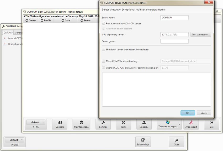
Table of Contents
1                 Introduction ........................................................................................................ 7
2                 Other COMPDM Data Model Elements .............................................................. 9
2.1               Process Tags ..................................................................................................... 9
2.2               Product Configuration Exchange: Effectivities, Dictionaries .............................. 12
2.2.1             Dictionary Objects ............................................................................................ 13
2.2.2             Effectivity Expressions...................................................................................... 15
2.2.3             Dictionary Mapping ........................................................................................... 17
3                 Mapping Patterns ............................................................................................. 19
3.1               Introduction ...................................................................................................... 19
3.2               Non-linear Mappings in the Process Monitor .................................................... 19
3.3               Automatic Merge of Instances .......................................................................... 20
3.4               Using Mapping Patterns ................................................................................... 21
3.4.1             Pattern Editor Dialog ........................................................................................ 22
3.4.2             The Role of the Pattern Variable Index ............................................................. 23
3.4.3             Considerations for Extension Mapping using Patterns ...................................... 24
3.4.4             Attribute Mapping for Mapping Patterns ........................................................... 25
3.4.5             Mapping Pattern Application ............................................................................. 26
4                 Multi-Server Configuration ................................................................................ 29
4.1               Overview .......................................................................................................... 29
4.2               Configuring Multi-Server Installations ............................................................... 30
4.2.1             Released Configuration for Secondary Servers ................................................ 30
4.2.2             Secondary Server Groups ................................................................................ 32
4.2.3             Interactive Configuration of Secondary Server ................................................. 33
4.2.4             Command-line Configuration of Secondary Server ........................................... 34
4.3               Working with Multi-Server Installations ............................................................. 35
4.3.1             Starting a Client Session .................................................................................. 35
4.3.2             Admin Client on Primary Server ....................................................................... 37
4.3.3             Admin Client on Secondary Server ................................................................... 38
4.3.4             Unavailability of Primary Server ........................................................................ 38
4.3.5             Switching a Secondary Server back to Primary Server ..................................... 39
5                 Scheduled Tasks .............................................................................................. 40
file name:   COMPDM-2021_04_AdvancedCustomization.docx          version: 2021           last revised:            2020-12-14
source:      Individual Development Suite 1.4.0                 status:   released      protection category: public                3/66
6                 Details of STEP AP242 Implementation ........................................................... 45
6.1               Handling of Properties ...................................................................................... 45
6.2               Handling of multiple Identifiers.......................................................................... 48
6.3               Handling of Alternate/Substitute parts .............................................................. 50
6.3.1             Alternate ........................................................................................................... 50
6.3.2             Substitute ......................................................................................................... 50
6.4               Handling of multiple view relationships (so-called ‘tracking’) ............................. 50
6.5               Change Management ....................................................................................... 51
6.5.1             WorkRequest ................................................................................................... 51
6.5.2             WorkOrder........................................................................................................ 51
6.5.3             Activity .............................................................................................................. 51
6.6               Mirrored Parts .................................................................................................. 51
6.7               Implementation Details ..................................................................................... 52
7                 REST Services for accessing Caches .............................................................. 54
7.1               resetCache/ (POST) ........................................................................... 54
7.2               subscribe/ (POST) .............................................................................. 55
7.3               getData//[/]maxCount (GET) ............................... 56
7.4               acknowledge/ or acknowledge// (POST) ......... 59
7.5               getFile// or getFile/// (GET) ........... 60
7.6               reset/ (POST) ............................................................................ 60
7.7               unsubscribe/ (POST) ................................................................. 60
7.8               putData/ (POST) ................................................................................. 61
7.9               putFile/// (POST) .................................................. 62
7.10              startProcess/// (GET) ............................................. 63
7.11              getProcessLog/ (GET) .................................................................. 64
Change History / Release Notes ....................................................................................... 65

file name:   COMPDM-2021_04_AdvancedCustomization.docx            version: 2021           last revised:            2020-12-14
source:      Individual Development Suite 1.4.0                   status:   released      protection category: public                 4/66
List of Figures
Figure 1: Scope of COMPDM ........................................................................................... 7
Figure 2: Define a Process Tag ........................................................................................ 9
Figure 3: Edit the Process Tag's Content .........................................................................10
Figure 4: Link Product Structure with Tag ........................................................................11
Figure 5: Example of Dictionary Representation when related to a Part (Teamcenter) ....14
Figure 6: Effectivity Attribute represented in Object Editor ...............................................15
Figure 7: Effectivity Expression Representation in Process Monitor Window ...................16
Figure 8: Defining the Mapping for Configuration Dictionary Elements.............................17
Figure 9: Mapping of Dictionary to local Part....................................................................18
Figure 10: Mapping Value from Part where local Dictionary is associated to....................18
Figure 11: "Mapping Patterns" section in Mapping Editor Window ...................................21
Figure 12: Pattern Editor Dialog .......................................................................................22
Figure 13: Alternate Types in Source Pattern ..................................................................23
Figure 14: Mapping Pattern Attribute Mappings ...............................................................25
Figure 15: Example for illustrating Alternative Matches ....................................................28
Figure 16: Settings Profile Domain ..................................................................................32
Figure 17: Primary Server Configuration Elements in Maintenance Dialog ......................33
Figure 18: Secondary Server Configuration Elements in Maintenance Dialog ..................33
Figure 19: Task Bar Menu Example for a Secondary Server ...........................................35
Figure 20:Login Dialog in Load Balancing Mode ..............................................................36
Figure 21: Table showing Status of Active Servers ..........................................................37
Figure 22: Secondary Server Admin Client with Reduced Functionality ...........................38
Figure 23: Scheduled Task Manager Window..................................................................40
Figure 24: Configure Automatic Execution Dialog ............................................................42
Figure 25: Filter Tab Details .............................................................................................43
Figure 26: Filter Match Interpretation ...............................................................................44
Figure 27: Limit Exported Product Structure Levels .........................................................44
Figure 28: Additional Elements for Property Classification (STEP AP242) .......................47
Figure 29: Example for Subscriber Information in Client ..................................................55

file name:   COMPDM-2021_04_AdvancedCustomization.docx    version: 2021         last revised:            2020-12-14
source:      Individual Development Suite 1.4.0           status:   released    protection category: public              5/66
List of Tables
Table 1: COMPDM Documentation ................................................................................... 8
Table 2: Dictionary Support in various Modules ...............................................................13
Table 3: Supported Effectivity Types per Module .............................................................16
Table 4: STEP AP242 Recommendations for Classification of Properties .......................46

file name:   COMPDM-2021_04_AdvancedCustomization.docx   version: 2021        last revised:            2020-12-14
source:      Individual Development Suite 1.4.0          status:   released   protection category: public           6/66
1            Introduction

The application COMPDM is designed to connect three worlds: product lifecycle man-
agement systems (PLM), computer aided design systems (CAD), and the international
standard ISO 10303 (STEP) for product data representation, exchange and long-term
archiving.

                                                         Figure 1: Scope of COMPDM

COMPDM clients allow for an easy definition and maintenance of data exchange pro-
cesses between any of these worlds. A very simple and straightforward user interface
allows the end user to start and monitor preconfigured exchange processes.

The COMPDM server manages and executes data exchange processes in a highly effi-
cient manner, including import to and extraction from PLM systems and conversions of
CAD files according to your requirements.

The present document is part of the COMPDM documentation, which is organized in sev-
eral volumes. The following table lists the available volumes and provides guidance about
the recommended readings for both data exchange administrators and data exchange
users.

file name:   COMPDM-2021_04_AdvancedCustomization.docx           version: 2021        last revised:            2020-12-14
source:      Individual Development Suite 1.4.0                  status:   released   protection category: public           7/66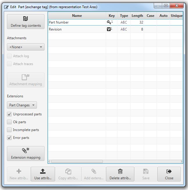
No.                 Title                                                       User             Administrator

     01             Installation                                                                            ✓
   02-A             User’s Manual (App Client)
                                                                                  ✓                         ✓
   02-B             User’s Manual (Browser Client)

     03             Basic Administration                                                                    ✓
     04             Advanced Customization
                                                                                                        (✓)
     05             Extended Customization with JAVA
                                                                                                        (✓)

Table 1: COMPDM Documentation

COMPDM has two different access modes:

      •      End user: To execute data exchange tasks such as data imports or exports and
             use all necessary supporting functionalities such as monitoring processes, con-
             firming imports to the PLM system, checking the results.
      •      Administrator (admin): Configuration of COMPDM, creation and modification of da-
             ta representations and data mappings, creation of pre-configured settings profiles,
             adding end user accounts, server maintenance. The administrator can also per-
             form the same tasks as the end user (i.e. run data exchange processes etc.)

The present document describes advanced configuration features and objects of
COMPDM, such as the exchange of product variant information, the definition of mapping
patterns for non-linear mappings, the management of multi-server installations, the con-
figuration of automatically repeated processes, and others.
The use of extended customization methods that make use of JAVA code to implement
complicated business rules and processes is described in the “Extended Customization
with JAVA” document.
It is assumed that the reader is familiar with volumes 02-A: “User’s Manual (App Client)”
and 03: “Basic Administration” of the COMPDM documentation.

file name:   COMPDM-2021_04_AdvancedCustomization.docx   version: 2021        last revised:            2020-12-14
source:      Individual Development Suite 1.4.0          status:   released   protection category: public           8/66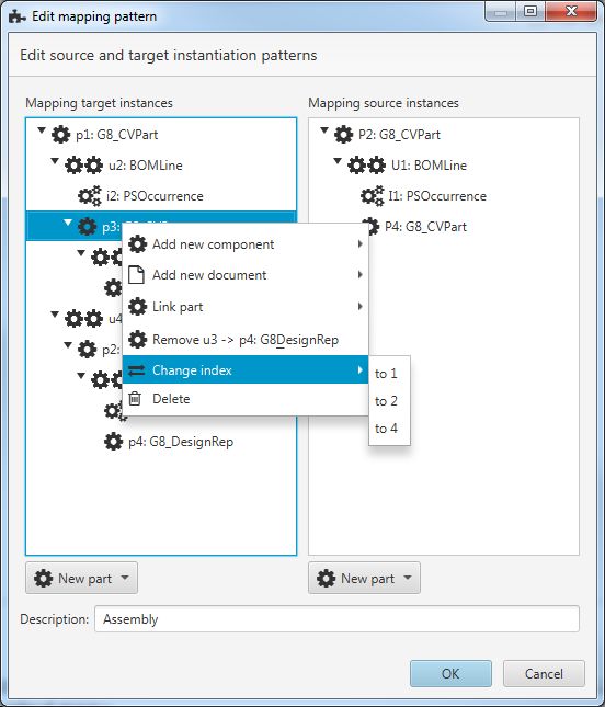
2            Other COMPDM Data Model Elements
In the Representation Editor Window (see volume 03 “Basic administration”, section 3.2,
the “Add other…” button allows to add some more object types to a representation, which
are described in the following sub-sections.

2.1             Process Tags
For PLM system based modules (i.e. Aras, Teamcenter, EnoviaV6, or VPM), it is possible
to add an “Exchange Tag” to a representation. This is a dedicated object in the PLM sys-
tem which is created to represent data exchanges: Whenever a process is executed
whose data exchange method includes this representation, an extra item will be created at
the end of the transfer (regardless of whether it is an import, or an export). This item, the
“Tag”, contains information related to the process itself1. It is possible to create a link be-
tween the tag and the exported or imported root part(s), or to every exported/imported
part. In addition, or alternatively, it is possible to create an extension of the tag object for
every processed part instance (e.g. to store processing details of all or some of the pro-
cessed instances). This allows to store information about data exchange processes per-
manently2, and to keep a history of all such events for every part.

To define a tag, first choose an item type to use for the tag3.

                                                         Figure 2: Define a Process Tag

1   The tag object’s consistency check method will be used to determine whether to actually create
the constructed tag. This allows implementing preconditions under which the tag is created, instead
of creating it always.
2   Remember that COMPDM keeps archived process information only for a configurable, but typical-
ly short time
3   You can choose among all available item types that could be used as a COMPDM part object. Of
course, it might make a lot of sense to customize a dedicated new item type for this purpose into
the PLM system.
file name:   COMPDM-2021_04_AdvancedCustomization.docx             version: 2021          last revised:            2020-12-14
source:      Individual Development Suite 1.4.0                    status:   released     protection category: public           9/66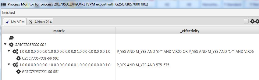
Next, open the tag object in the Object Editor window. You will notice that the Object Edi-
tor’s left-hand elements are different in comparison with editing objects such as parts,
assemblies, instances or documents:

                                                  Figure 3: Edit the Process Tag's Content

Use the “Define tag contents” button to define how the pro-
cess properties4 should be mapped to the tag item’s attrib-
utes.
The mapping works as usual, i.e. you may use any of the mapping alternatives of
COMPDM, including customized JAVA code, to compute the tag’s attribute values. Refer
to section 4 of the “Basic Administration” manual of COMPDM for details. There is one
additional element:

4   Process ID, process type (data exchange method), profile, user, input data description, start time,
end time, status, contents of process log
file name:   COMPDM-2021_04_AdvancedCustomization.docx           version: 2021               last revised:            2020-12-14
source:      Individual Development Suite 1.4.0                  status:   released          protection category: public           10/66
At the bottom of the tag item attribute list you find a “Link to ” selector for every part
object type in the representation:
Figure 4: Link Product Structure with Tag
If you want to have links created from the tag object to the exported or imported root
part(s)5, select the relationship type to use for this link. Check “each ” in addition if
you want the links to be created not only for the root parts, but for every part in scope.
To make COMPDM attach the process log file and/or the process
trace file to the tag, use the „Attachments“ selector to choose one
of the available document item types for them.
You may then use the “Attachment mapping” button to specify how
the document’s attributes shall be filled.
Note that it might be necessary to add the document type to the representation first. After
having specified the document attribute mapping, the document object can be removed
from the representation again if it is not needed in the context of product structure ex-
change.
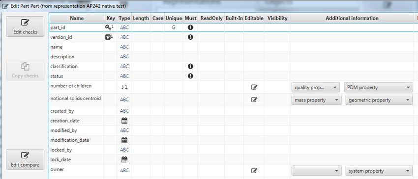
There is also the option of creating an extension instance for all processed part instances.
To do this, first add the tag’s item type as a “Part” object (if not yet present) and add the
extension type to the “Part” that you want to use for the tag.
Configure the extension attributes using the Object Editor on
the part.
Next, you can select the extension type when editing the tag
object in the Object Editor. Use the filters to specify which
final processing status qualifies a part for having an extension
instance created at the tag (in the example to the right, such
an extension will be created for all parts that either have er-
rors or remain unprocessed). Use the “Extension mapping”
button to specify how the part instance’s processing infor-
mation6 shall be mapped to the extension. Again, all mapping
alternatives, including custom JAVA code, can be used.
You may then remove the extension and the part from the representation if they were only
added to support the definition of the tag.
5 For example, when importing STEP data, the imported product structure may have several root
elements. The same applies for other import sources, when the root element gets excluded manu-
ally from the import scope
6 Key (concatenation of all key and version attribute values), OID (PLM object id), Messages (all
instance related messages collected during processing), and Status (processing status)
file name: COMPDM-2021_04_AdvancedCustomization.docx version: 2021 last revised: 2020-12-14
source: Individual Development Suite 1.4.0 status: released protection category: public 11/662.2 Product Configuration Exchange: Effectivities, Dictionaries Products in the real world often have many variants. In PLM systems, it is common prac- tice to have one common product structure which includes all possible components of any variant of the product, i.e. a so-called “150% bill of material”. An actual variant of the product contains only a sub-set of all possible components. Wherever there are several alternate components available, of which only one (or at most one) should be included in a product variant, effectivity conditions are used to describe when each of the components should be included in a particular product variant. These conditions can be time based (i.e. some component shall be used during a certain interval of time), based on serial number ranges, and on a logical combination of configuration options. These configuration options are organized in configuration categories, each with a set of alternate options that can be selected. The sum of all available configuration categories makes up the configuration dictionary. In some cases, the configuration dictionary is globally defined in the PLM system (e.g. Aras), in others, it is locally defined for a product (e.g. Teamcenter), or both alternatives are available (e.g. VPM). COMPDM supports the exchange of effectivity conditions and configuration dictionaries, at least for basic configuration functionality. In the case of CATIA and NX, effectivity ex- pressions can be mapped to and from a user defined property, whereas dictionaries can- not be mapped. For a full-scale exchange of configuration information, the STEP format is by far more suitable than CATIA or NX native exchange processes. Note that as of version 2.3 of COMPDM, the new EnoviaV6 module does not yet support the exchange of product configuration information. This is planned for the next release (end of 2019). file name: COMPDM-2021_04_AdvancedCustomization.docx version: 2021 last revised: 2020-12-14 source: Individual Development Suite 1.4.0 status: released protection category: public 12/66
2.2.1               Dictionary Objects

Local or global dictionary objects can be added for PLM based representations (i.e. Aras,
Teamcenter, VPM), and STEP.

Module                     Local                  Global   Remarks
Aras7                                                      A global dictionary contains all configuration catego-
                             n/a                   ✓       ries and options

Teamcenter                                                 One of the part types of the representation has to be
                             ✓                     n/a     chosen for the dictionary. 8

VPM                                                   If local dictionaries are to be used, one of the part
                                                      types of the representation has to be chosen. Other-
                             ✓              Corporate
                                                      wise (i.e. for Corporate dictionary), select “None
                                                      (Corporate)” from the dictionary type selector.
Enovia V6
                                                                Not yet supported

Windchill

                                                                Not yet supported

STEP                                                       Dictionary has a “Product id” attribute. Dictionary
                             ✓                     n/a     gets mapped to a “Product class” entity. “Product id”
                                                           defaults to “unspecified”
CATIA, NX                                                  When mapping effectivities from CATIA/NX proper-
                                                           ties, an “implicit” dictionary is constructed from the
                             n/a                   n/a
                                                           options used within the effectivities. This object may
                                                           then be used in mapping definitions.

Table 2: Dictionary Support in various Modules

Each dictionary object has a “Content” attribute that collects configuration categories (with
id and optional description), each of which carries a number of options (with id and op-

7   COMPDM’s implementation for Aras is based upon a proprietary extension for configuration
management developed by T-Systems. Support for the new configuration management features of
Aras Corp is planned for future releases of COMPDM.
8   In Teamcenter, COMPDM configuration categories are called „Classic options“ and COMPDM
configuration options are called „option values“
file name:   COMPDM-2021_04_AdvancedCustomization.docx          version: 2021        last revised:            2020-12-14
source:      Individual Development Suite 1.4.0                 status:   released   protection category: public           13/66
tional description). Further information such as whether a category is mandatory or
whether there is a default option value, is not supported.
In the case of Aras and STEP, when adding a dictionary object to a representation, the
object is fixed and cannot be edited, only removed. In the case of Teamcenter and VPM,
when adding a dictionary object to a representation, the object type for local dictionaries
may be (VPM) or has to be (Teamcenter) chosen from one of the “Part” object types al-
ready included.
When running data exchanges, the attribute values of this associated part are shown in
addition to the dictionary’s “Content”:
Figure 5: Example of Dictionary Representation when related to a Part (Teamcenter)
When data is exported from a PLM system, a dictionary object can be included either im-
plicitly or explicitly:
• Implicitly, all options that are used within the exported product structure will be
contained in one or more dictionary objects, together with the configuration catego-
ry they belong to, and any other options for the same category, regardless of
whether they are used within the exported product structure or not. The category
definition is thus automatically complete. However, if the dictionary in the PLM sys-
tem contains other configuration categories whose options are not part of effectivi-
ty expressions in the exported product structure, these are not exported.
In the case of Teamcenter, COMPDM will use the information from the variant
condition to find the corresponding dictionary and category (classic option) defini-
tion.
In the Aras and VPM case, only the global (corporate) dictionary is searched for
them.
In the VPM case, export from a local dictionary is only supported in the context of
“Automatic processes” (see section 4).
If effectivity data is mapped from a CATIA/NX property (see “Basic Administration”
Manual, section 3.6.2), an implicit Dictionary is constructed, which only contains
the categories and options used within the exchanged product structure. If the ef-
fectivity expressions contain different product id references, several implicit dic-
tionary instances may be found.
file name: COMPDM-2021_04_AdvancedCustomization.docx version: 2021 last revised: 2020-12-14
source: Individual Development Suite 1.4.0 status: released protection category: public 14/66• Dictionaries can be included explicitly in a data export, but this is only supported in
the context of “Automatic processes” (see section 4). For export processes that
are started manually, direct selection of a dictionary is not possible.
If a dictionary is exported explicitly, COMPDM will export all categories and op-
tions, regardless of whether they are used in effectivity expressions or not.
In the import case, when an existing dictionary gets updated, COMPDM will always work
in an additive manner, i.e. it will add any new categories or configuration options but never
remove existing categories or options.
2.2.2 Effectivity Expressions
For the exchange of effectivity expressions, add an attribute of type “Effectivity” to your
representation. For Teamcenter, VPM and STEP this attribute has the name
“_effectivity”, for Aras, its name is “ts_configuration_expression”. It can be
“Used” for Instance objects, in some cases also for Assembly objects.
Figure 6: Effectivity Attribute represented in Object Editor
In the case of CATIA and NX, add a user defined property with any name and change its
type to “Effectivity (§§)”. On export to CATIA/NX, COMPDM will encode the effectivity ex-
pression as a string, and on import, it will parse this string and reconstruct the effectivity
expression. This allows exchanging configuration effectivities using a CATIA/NX file-
based data exchange, provided that COMPDM is used on both ends of the exchange.9
COMPDM currently supports the following effectivity expressions:
Module Supported effectivity types
Aras Complete data model with the exception of lots and milestones. No distinc-
tion is made between rank and range options.
Teamcenter Variant conditions based on (string type) classic options. Only operators EQ
and NEQ are supported. In addition, export supported for occurrence effec-
tivities based on date ranges
9 Also note that such a process implies that instance-based attributes (PLM effectivity) are mapped
to/from part-based properties (CATIA/NX). COMPDM will not attempt to resolve any ambiguities
that can arise in such mappings, in other words, such a process would require some additional
considerations.
file name: COMPDM-2021_04_AdvancedCustomization.docx version: 2021 last revised: 2020-12-14
source: Individual Development Suite 1.4.0 status: released protection category: public 15/66VPM
Date effectivities, range effectivities, pack and option effectivities, “not” flag.
Not supported: Milestones, programs, if-then-rules, compatibility matrices.
STEP Occurrence effectivities based on date ranges and serial ranges, specifica-
tion category, specification, specification expression.
Not supported: LotEffectivity, TimeIntervalEffectivity, DataValidityEffectivity
on Events (Milestones), RevisionEffectivity
Table 3: Supported Effectivity Types per Module
In the Process Monitor, COMPDM will use a system independent format for representing
effectivity expressions, where parentheses are only used if operator precedence (NOT >
AND > OR) makes them necessary:
Figure 7: Effectivity Expression Representation in Process Monitor Window
When comparing effectivity expressions e.g. during reconciliation, COMPDM will flag any
structural differences of the expression as a modification, regardless of whether the result-
ing logical expression is actually different. Non-structural changes such as a change in the
order of operands are not considered to be a modification. For example, “NOT (A AND B)”
will be considered to be the same as “NOT (B AND A)”, but not the same as the logically
equivalent “(NOT A) OR (NOT B)”.
When importing effectivity expressions which contain NOT operators to Teamcenter,
which does not have a “NOT” operator in its variant conditions, COMPDM will automatical-
ly transform the expression to a semantically equivalent expression without using the NOT
operation.
Also note that COMPDM by default will only update variant conditions in Teamcenter if the
corresponding effectivity expression is different from the incoming data. Changes in the
dictionary association of the options are not considered to make a difference in this con-
text, so if this is the only change, the variant condition will not get updated10.
10 Post reconciliation (“Match”) JAVA code could be used to manipulate the internal representation
of the Teamcenter effectivity expression in order to enforce an update of the variant condition, see
volume 05: “Extended Customization with JAVA”
file name: COMPDM-2021_04_AdvancedCustomization.docx version: 2021 last revised: 2020-12-14
source: Individual Development Suite 1.4.0 status: released protection category: public 16/662.2.3 Dictionary Mapping
If the target representation includes a Dictionary object, the Mapping Editor’s left-hand
“accordion” contains an additional entry for the “Dictionary” objects (see “Basic administra-
tion”, section 4.2).
Figure 8: Defining the Mapping for Configuration Dictionary Elements
Mapping definitions for the elements in a dictionary are much more restricted than for oth-
er kinds of objects:
When you choose “source” mapping for “Category description”, “Category id”, “Option
description”, or “Option id”, you can only use the same property from the source dictionary
object.
In the case of the “Product id” (if present), source mapping allows to map from either the
source dictionary’s “Product id” (if present), or from attribute values of the root part of the
exchanged structure (see example in the figure above). However, in case there are sev-
eral root parts in the exchanged product structure, the result will be ambiguous (the use of
“code” type mappings as explained in volume 05 of the documentation is preferable in
such cases).
file name: COMPDM-2021_04_AdvancedCustomization.docx version: 2021 last revised: 2020-12-14
source: Individual Development Suite 1.4.0 status: released protection category: public 17/66If the target representation uses a local dictionary, i.e. a dictionary is associated with a
part in the PLM system (Teamcenter, optionally VPM), two mappings have to be defined:
• One for the Dictionary contents (Categories and Options)
• One for specifying the target part
Figure 9: Mapping of Dictionary to local Part
In such cases, the method only becomes executable when both the mapping to the target
dictionary and the mapping to the target part have been specified.
If, on the other hand, the source representation uses a local dictionary, the dictionary re-
lated mappings can use any attribute of the part as a mapping source. The source attrib-
ute selection dialog will allow selection of these attributes under “Part”, in addition to the
root part’s attributes as described above:
Figure 10: Mapping Value from Part where local Dictionary is associated to
file name: COMPDM-2021_04_AdvancedCustomization.docx version: 2021 last revised: 2020-12-14
source: Individual Development Suite 1.4.0 status: released protection category: public 18/663 Mapping Patterns 3.1 Introduction Mapping patterns are used to create “forks” or “joins” in the mapping of a source product structure to a target product structure. An instance does not necessarily have a fixed life span that starts with the source representation and ends at the target representation. Ra- ther, an instance can be created during a mapping process, or can cease to be handled any further. A mapping pattern can also change the related objects for a particular in- stance. We refer to these situations as “non-linear mappings”. As will be seen further below, COMPDM allows for a very easy definition of such structural changes in a graphical way as “instantiation patterns” or “mapping patterns”. A merge mechanism ensures that two instances that end up with identical key attributes after a mapping are merged into one. This merging is likewise active for simple, linear “Object Object” mappings as described in section 4 of the “Basic Administration” manual and therefore the proper definition of key/version attributes in the Object Editor (see 3.3.1 of “Basic Administration” manual) is very important to avoid unwanted merge operations. 3.2 Non-linear Mappings in the Process Monitor A consequence of non-linear mappings is that the product structures in the different views of a process’ data visualization can be different. The Process Monitor offers a toggle but- ton in such cases which allows to select either a “connected” or a “disconnected” repre- sentation (refer to section 2.4.4 of COMPDM’s “User’s Manual”). file name: COMPDM-2021_04_AdvancedCustomization.docx version: 2021 last revised: 2020-12-14 source: Individual Development Suite 1.4.0 status: released protection category: public 19/66
3.3             Automatic Merge of Instances
Whenever in a mapping step from one representation to the next, the attributes of an ob-
ject have been calculated, the kernel checks whether the instance can be merged with
another one. If this is the case, the merged instance will carry the attributes of both map-
ping operations. When one of them did not calculate a value for a particular attribute (i.e. it
was “null”), but the other did, the result will contain the value.
In case the two mapping operations resulted in different, but non-“null” values, a warning
is issued with the instance and one of the values is kept.
The decision whether to merge two instances is made based upon the “key signature” for
parts, documents, assembly instances, and extensions. For usages, the criterion is the
parent and the child part’s key signatures.
The key signature is a concatenation of all key and version attribute value.
      •      If the document is not defined as having globally unique keys, document instances
             are only merged with documents of the same part (if at all) or with documents that
             emerge from mapping pattern application
      •      If no key or version attributes are defined for documents or extensions, they are
             never merged
      •      Assembly instances are only merged with assembly instances for the same usage
             (parent / component combination). If no key or version attributes are defined for an
             assembly instance type, they are never merged.
      •      Parts with no key and version attributes likewise are never subject to merging.
      •      In any case, merging only applies for instances of the same object type
Note that in the context of mapping patterns, COMPDM uses a very declarative approach
which can generate many target instances for a certain source product structure. The
merge mechanism is then the key to manageable results. This means that the choice of
key attributes and computation of their target values should be given some consideration.

file name:   COMPDM-2021_04_AdvancedCustomization.docx   version: 2021        last revised:            2020-12-14
source:      Individual Development Suite 1.4.0          status:   released   protection category: public           20/66
3.4 Using Mapping Patterns
The Mapping Editor Window’s left side features a section labeled “Mapping patterns”,
which contains all mapping patterns defined for the mapping. Each pattern is shown with
an iconic representation.
Figure 11: "Mapping Patterns" section in Mapping Editor Window
A Mapping Pattern consists of a source instantiation pattern and a target instantiation pat-
tern.
• Use the “New pattern…” button to open the Pattern Editor dialog for a new, empty
mapping pattern (see 3.4.1)
• Move the mouse over the pattern’s iconic representation to see a popup with the
complete pattern structure
• Single-click on a pattern’s icon to load its attribute mapping definitions into the
right-hand side of the Mapping Editor window and edit them (see 3.4.2)
• Double-click on a pattern’s icon to open the Pattern Editor dialog for it for inspec-
tion or modification of the pattern (3.4.1)
• Use the right mouse button on a pattern’s icon to access a context menu that al-
lows to delete a pattern (after confirmation), or to create a clone (identical copy) of
it
• Like the conventional (Object Object) mapping declarations, the pattern’s icon
has a little symbol to the left that indicates whether the mapping is disabled, and if
not, whether it is executable (see 3.4.3; in the example above, the “Test pattern” is
not executable).
file name: COMPDM-2021_04_AdvancedCustomization.docx version: 2021 last revised: 2020-12-14
source: Individual Development Suite 1.4.0 status: released protection category: public 21/663.4.1 Pattern Editor Dialog
The Pattern Editor dialog allows creation or modification of a mapping pattern. Each map-
ping pattern consists of a source instantiation pattern based on objects of the source rep-
resentation11, and a target instantiation pattern based on objects of the target representa-
tion.
Figure 12: Pattern Editor Dialog
The starting point for every instantiation pattern is always a part object type. Use the “New
part” button to add a new “root” part instance variable for an instantiation pattern. You may
then add documents, components, component instance, and extension variables to the
root part using the part’s context menu.
Each instance variable in the pattern automatically gets assigned a name upon creation.
This name is one of the letters P, U, I, D, X for parts, usages, assembly instances, docu-
ments, and extensions, respectively, and a unique counter (index). The variable names in
the target pattern are in lowercase, whereas the names in the source representation are in
uppercase.
11 Parts, Documents, Usages, Assembly Instances, or Extensions – i.e. Dictionary and Tag are not
supported in mapping patterns
file name: COMPDM-2021_04_AdvancedCustomization.docx version: 2021 last revised: 2020-12-14
source: Individual Development Suite 1.4.0 status: released protection category: public 22/66Like the Process Monitor window, the Pattern Editor dialog uses a tree representation of
the instantiation pattern, but the instantiation pattern is not restricted to a tree. Rather it
can be any directed acyclic graph, and you can e.g. re-use components freely, if no cycle
is induced.
In the lower section of the dialog, a descriptive text can be entered for the pattern. It is
used throughout the user interface and in traces as a reference to the pattern but is not
required to be unique.
You may add several root instance variables to any instantiation pattern but be cautious
with this in the case of the source representation as it can drastically enlarge the computa-
tional complexity of applying the pattern, especially for large product structures.
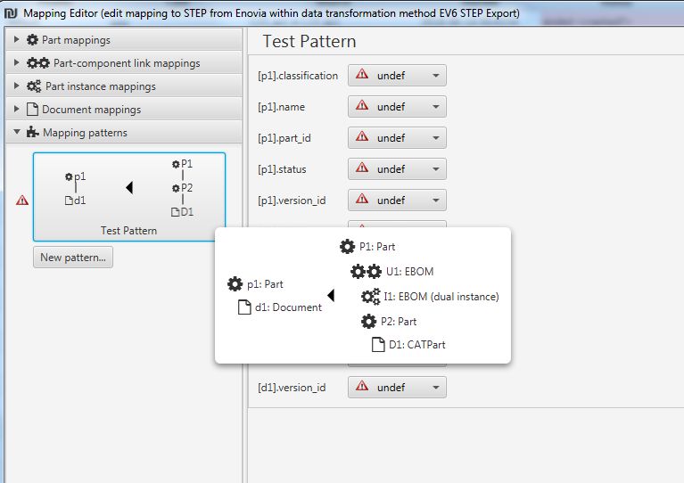
In the source instantiation pattern (right), it is possible to specify several object types for
the same pattern variable, provided that the corresponding object category has more than
one. Instances of any of the object types can then match the variable. Use the context
menu’s “Add type” and “Remove type” entries to control alternate types.
Figure 13: Alternate Types in Source Pattern
In the example above, the pattern variable D1 can be matched by an object of type “CAD”
or an object of type “Document”, whereas D2 can only be matched by a “CAD”. The
source pattern thus requires a “Part” which possesses one “CAD” and at least one addi-
tional “CAD” or “Document”.
3.4.2 The Role of the Pattern Variable Index
The index of a variable in the pattern has some significance in the mapping process.
When possible, the mapping target of a source instance that matches the source pattern
will become the instance of the target pattern with the same name (except for the upper-
case/lowercase writing, that is). For example, in the screenshot above, the instance of
“G8_CVPart” which stands for “P4” in the mapping will have the “G8_DesignRep” created
for “p4” as its representation in the target view; the instances “p1” and “p3” will be created
by the pattern and have no source view representation, at least not from this mapping
pattern.
Use the “Change index” context menu function in the Pattern Editor dialog to swap a vari-
able’s index with another one’s. This allows controlling the target correspondence of a
source object directly.
file name: COMPDM-2021_04_AdvancedCustomization.docx version: 2021 last revised: 2020-12-14
source: Individual Development Suite 1.4.0 status: released protection category: public 23/66In the attribute mapping section of a pattern, the “Index override”
checkbox allows to specify whether index coincidence of source and
target variable overrides merging by “same key” or not. Checking it may be necessary if
mapping patterns are used in conjunction with linear “Object Object” mappings and/or a
pattern changes key/version attributes of an instance. Consider a case where a source
part P1 should be revised under certain circumstances, and a pattern shall introduce a
relation between old and new revision. From a “pattern point of view”, p1 should be the
name of the new revision (so that all attached documents etc. remain with the new revi-
sion) and e.g. p2 the name of the old revision. P1 and p1 should be the representations of
the same part in the source and target view, and p2 should be an additional instance in-
troduced by the pattern. However, in case a linear mapping (Object Object) has already
created an unrevised target instance (for those cases where revising is not required), the
merge mechanism would automatically choose p2 to represent P1’s target view due to
key/version coincidence. Related objects (documents, components etc.) would then relate
to the old revision unless explicitly modelled in the pattern (which would complicate pat-
tern definition considerably). By checking “Index override”, it can be ensured that a source
instance’s target representation will be the pattern variable with the same index even if the
merge mechanism would choose a different target instance.
In the case of dependent instances such as documents, assembly instances, or exten-
sions, structural requirements may override the connection of source and target instance
with the same index to avoid over-complicated results in the Process Monitor view-
spanning product structure tree representation.
3.4.3 Considerations for Extension Mapping using Patterns
Observe that the complications of internal extension mapping (as described in 4.3.4 of the
“Basic Administration” manual) for the multi-instance cases are not present when using
mapping patterns, as the pattern drives the count of target extension instances that get
computed, and each instance’s attribute value is specified directly from the source instan-
tiation pattern like with the other instance types.
Make use of key or locally unique attributes in the extension object definition to enable
merging of created extension instances where necessary.
file name: COMPDM-2021_04_AdvancedCustomization.docx version: 2021 last revised: 2020-12-14
source: Individual Development Suite 1.4.0 status: released protection category: public 24/663.4.4 Attribute Mapping for Mapping Patterns
After clicking on a mapping pattern’s iconic representation, the Mapping Editor window
shows the mappings for all the target attributes.
Figure 14: Mapping Pattern Attribute Mappings
At first glance, the attribute mapping definitions resemble the ones known from the con-
ventional „Object Object“ mappings, however there are the following differences:
• Target attributes are grouped by target instance name and their name is prepend-
ed with the name of the corresponding target instance.
• In the case of “source” type mappings, the source value is always picked from one
of the source instantiation pattern instances.
• “As” mappings (described in 4.2.1 of “Basic Administration” manual) are not sup-
ported
• The mapping wizard (see 4.2.2 in “Basic Administration” manual) does not operate
on mapping patterns
• In larger target patterns, the number of attribute mapping rows can quickly grow
with the number of instances, rendering the view rather confusing. The checkbox
“Hide optional attributes if undefined” can be quite useful for keeping an overview.
file name: COMPDM-2021_04_AdvancedCustomization.docx version: 2021 last revised: 2020-12-14
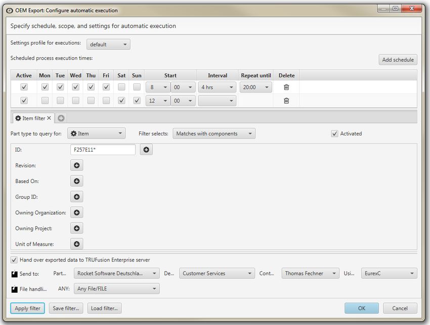
source: Individual Development Suite 1.4.0 status: released protection category: public 25/663.4.5 Mapping Pattern Application
A mapping pattern is executable, if:
• Neither source nor target instantiation pattern are empty
• Neither source nor target instantiation pattern contain objects types that are not
part of the corresponding representations12
• All key, version, and mandatory attributes of all target instantiation pattern varia-
bles have a mapping defined
• The pattern’s execution precondition is satisfied
When some source representation object type is part of an executable mapping pattern,
the mapping can become executable even if no linear (“Object Object”) mapping or
“Target selection” method is defined for that source object type. The idea is that mapping
patterns can be used in combination with, or instead of, these conventional mappings.
For full control over the mapping process, it might be necessary to disable direct map-
pings via the context menu, as described in section 4.2.1 of the “Basic Administration
Manual”.13
The execution precondition of the mapping pattern is controlled via buttons at the top of
the attribute mapping section. You can choose among four alternatives:
• No: The pattern is disabled, i.e. not executed automatically. It can still be invoked
via custom JAVA code (refer to the “Extended Customization using JAVA” manual,
section 4.3.2)
• Table: The pattern is executed for all combinations of source instances that match
the source pattern, if in addition some single source attribute, or a combination of
source attributes, have certain values (wildcards allowed). The “Edit…” button
opens a dialog which allows to specify the source pattern attributes, values, and
conjunction (and/or).
• JAVA code: The pattern is executed for all combinations of source instances that
match the source pattern, if in addition a user defined method returns true after
checking some conditions. Use the “Edit…” button to define or modified this code.
Refer to the “Extended Customization using JAVA” manual, section 3.3.3)
• Always: The pattern is always executed for all combinations of source instances
that match the source pattern.
When mapping a product structure from some source to a target representation, executa-
ble mapping patterns are applied after the direct mappings for parts and documents are
12 Such a situation can occur in case one of the representations is modified after pattern creation
13 This is particularly useful in the case of target object types without mandatory or key attributes,
which are always executable
file name: COMPDM-2021_04_AdvancedCustomization.docx version: 2021 last revised: 2020-12-14
source: Individual Development Suite 1.4.0 status: released protection category: public 26/66run14, but before direct mappings for relations (usages and instances) have executed. This execution order simplifies relation mappings for situations where the parts/documents are mapped exclusively by patterns. If both types of mappings are in use, the automatic merge of instances (see 3.3) should be used. The benefit is that mapping details of an object instantiation can be removed from the mapping pattern. A pattern can, through merging, reassign a document to a dif- ferent part, but a prerequisite is that at least one document key attribute is defined to be globally unique. For every source part instance in the product structure to be mapped, all executable, ena- bled mapping patterns are tested where the first root variable of the source instantiation pattern matches the part type. It is checked whether the relations (component types, doc- ument types) described by the source pattern are present at the source part instance. If additional root part variables are present in the source pattern, all combinations with cor- responding part instances from the source population are tested likewise. If a combination of source instances fulfils the pattern, and the precondition is satisfied (if applicable), the mapping pattern is applied to instantiate the target instances. If successful for all target pattern elements, the kernel will execute the target instance’s consistency check methods15. If they succeed for all instances, the created instances become a part of the target product structure representation by either merging with previously created in- stances or adding new instances. If necessary, the consistency check method16 can be implemented in a manner that it be- haves differently when executed for a pattern instantiation than when executed for a direct (“Object Object”) mapping. This can be recognized as the “___reprIndex” parameter has the value 0 uniquely in the pattern consistency check case. 14 Note that dictionary mappings are executed before mapping pattern application. The reason is that the mapping of effectivity expressions can thus take any renaming of configuration options or categories into account 15 At this point, the instances are part of a „sandbox“ product structure containing only the target pattern instantiation. Using JAVA code, it is thus possible to access other instances in the target pattern for consistency checks, but neither any other instances outside the pattern nor the data representations of the mapping’s source representation (or any earlier representation) 16 Accessible via Object Editor, “Edit checks…”, see 3.3.4 of “Basic Administration” manual for location and “Extended Customization with JAVA” manual for implementation details file name: COMPDM-2021_04_AdvancedCustomization.docx version: 2021 last revised: 2020-12-14 source: Individual Development Suite 1.4.0 status: released protection category: public 27/66
If other combinations of source instances match the pattern likewise, instantiation is per-
formed for these likewise. The kernel will generate all valid combinations except for those
where only the order of object instances of equal type is different.
Consider the following example:
Figure 15: Example for illustrating Alternative Matches
The source pattern (right-hand) matches any source part with at least 2 component parts
and one document. The intent may be the creation of an extra component for the docu-
ment in such cases.
• If the source part instance has 2 components A and B, either p2A + p3B or
p2B + p3A will be generated, but not both
• If the source part instance has 3 components A, B, and C, the assignments p2A
+ p3B, p2A + p3C, and p2B + p3C will be generated, each variant with
possibly swapped assignment of same source component
To summarize, COMPDM’s mapping pattern matching relies on a purely structural de-
scription of the preconditions for application, plus an optional precondition, plus consisten-
cy checks of the created instances (post condition). This makes the definition of mapping
patterns fairly simple, for the price of elevated computation load.
file name: COMPDM-2021_04_AdvancedCustomization.docx version: 2021 last revised: 2020-12-14
source: Individual Development Suite 1.4.0 status: released protection category: public 28/664 Multi-Server Configuration
4.1 Overview
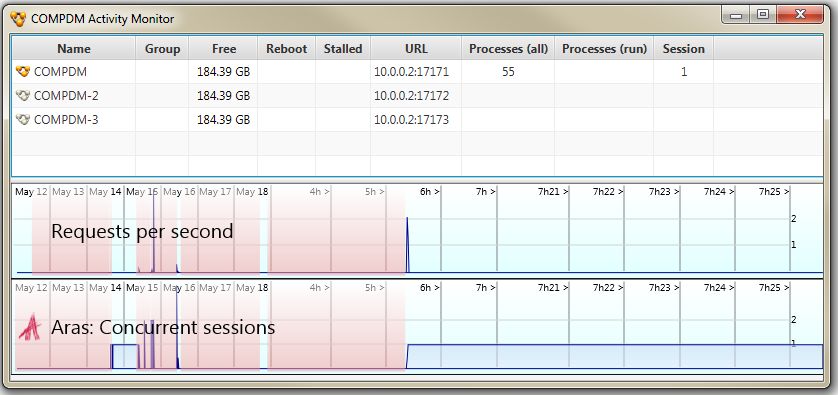
A COMPDM multi-server configuration consists of a primary server and one or more
secondary servers.
The primary server (showing the golden COMPDM logo) is used to create or
modify users, profiles, representations and data exchange methods, and
manages all secondary servers. This includes a complete view of all processes
on all servers.
Secondary servers (showing the silver COMPDM logo) can execute data
exchange methods defined on the primary server, by creating local processes,
and allows users to review them.
At any time, the current configuration of the primary server can be “released”, which
means a snapshot of all executable data exchange methods is made which is then
distributed to all secondary servers.
Multi server configurations can be used for the following purposes:
• Globally distributed PLM system or TRUfusion Enterprise installations can be
mirrored by distributed secondary COMPDM servers in order to avoid long
distance network traffic for the CAD data imported/exported.
• Customers with a large user base and many exchange processes running in
parallel can easily assign multiple servers and have the workload divided among
them automatically.
• By installing a secondary server on the same host as the primary COMPDM
server, further evolvement of the data exchange methods can be done without the
risk of disturbing production use of current data exchange methods due to
temporary inconsistencies etc17.
17 Decoupling configuration development from production use is a standard feature available to all
COMPDM installations, because one local secondary server (i.e. which runs on the same host as
the primary server) is supported by the base COMPDM server license (901). Further local or non-
local secondary servers however require a 902 license each.
file name: COMPDM-2021_04_AdvancedCustomization.docx version: 2021 last revised: 2020-12-14
source: Individual Development Suite 1.4.0 status: released protection category: public 29/66You can also read