CIFX M223090AE-RE F User manual - Hilscher Gesellschaft für Systemautomation mbH www.hilscher.com
←
→
Page content transcription
If your browser does not render page correctly, please read the page content below
User manual
                                   CIFX M223090AE-RE\F
PC card PCI Express M.2 2230 A-E Real-Time-Ethernet
                                              Slave

    Hilscher Gesellschaft für Systemautomation mbH
                                   www.hilscher.com
DOC190704UM05EN | Revision 5 | English | 2021-05 | Released | Public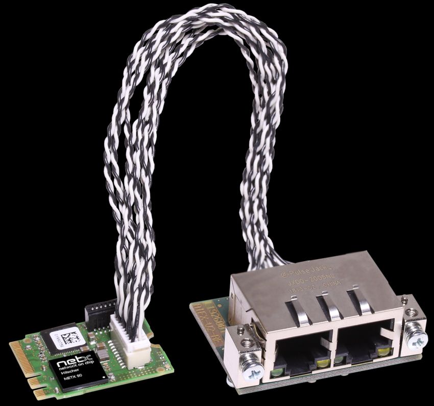
Table of contents                                                                                                                            2/62

                                                       Table of contents
1   Introduction .............................................................................................................................. 4
    1.1      About the user manual ..................................................................................................... 4
    1.2      List of revisions ................................................................................................................ 4
2   Devices and accessories ........................................................................................................ 5
    2.1      Basic card CIFX M223090AE .......................................................................................... 6
    2.2      Detached network interface AIFX-V2-RE......................................................................... 7
    2.3      Product software .............................................................................................................. 8
    2.4      Revision or version status of hardware and software ...................................................... 8
    2.5      Device label with matrix code........................................................................................... 9
3   Safety ...................................................................................................................................... 10
    3.1      General note .................................................................................................................. 10
    3.2      Intended use .................................................................................................................. 10
    3.3      Personnel qualification ................................................................................................... 10
    3.4      Safety messages............................................................................................................ 11
             3.4.1   Electrical shock hazard ................................................................................... 11
             3.4.2   Personal injury, device damage due to hot swap/hot plug.............................. 11
    3.5      Property damage............................................................................................................        12
             3.5.1    Excessive supply voltage................................................................................                  12
             3.5.2    Excessive signaling voltage ............................................................................                  12
             3.5.3    Electrostatically sensitive devices...................................................................                    12
             3.5.4    Power drop during write and delete accesses in the file system ....................                                       13
             3.5.5    Exceeding the maximum number of permitted write and delete accesses .....                                                 13
    3.6      Information and data security......................................................................................... 13
    3.7      Warnings ........................................................................................................................ 14
4   Installing the hardware.......................................................................................................... 15
    4.1      System Requirements.................................................................................................... 15
    4.2      Requirements for operation............................................................................................ 17
    4.3      Overview installation and firmware download ................................................................ 18
    4.4      Installing the hardware ................................................................................................... 19
    4.5      Loading firmware and configuration in the device or making an update ........................ 20
    4.6      Hints for problem solving................................................................................................ 21
    4.7      Uninstalling the hardware............................................................................................... 22
    4.8      Disposal of waste electronic equipment......................................................................... 22
5   Diagnosis with LEDs ............................................................................................................. 23
    5.1      Overview ........................................................................................................................ 23
    5.2      System LED ................................................................................................................... 24
    5.3      EtherCAT Slave ............................................................................................................. 25
    5.4      EtherNet/IP Adapter (V3/5) ............................................................................................ 27
    5.5      OpenModbusTCP .......................................................................................................... 29
    5.6      PROFINET IO-Device .................................................................................................... 30

CIFX M223090AE-RE\F | Hardware description and installation                                                            © Hilscher 2019 - 2021
DOC190704UM05EN | Revision 5 | English | 2021-05 | Released | Public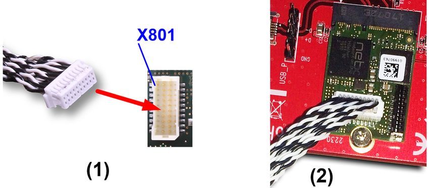
Table of contents                                                                                                                         3/62

6   Connectors ............................................................................................................................. 31
    6.1      Ethernet RJ45 socket..................................................................................................... 31
    6.2      Data of the Ethernet connection..................................................................................... 32
    6.3      Usability of hubs and switches ....................................................................................... 32
    6.4      Cable connector Ethernet X801, on CIFX M223090AE ................................................. 33
    6.5      PCI Express M.2 bus ..................................................................................................... 34
7   Technical data ........................................................................................................................ 36
    7.1      PC card CIFX M223090AE-RE\F................................................................................... 36
    7.2      PCI identifiers on the PCI Express M.2 bus ................................................................... 37
    7.3      AIFX-V2-RE ................................................................................................................... 38
    7.4      Communication protocols...............................................................................................          39
             7.4.1 EtherCAT Slave ..............................................................................................             39
             7.4.2 EtherNet/IP Adapter........................................................................................               41
             7.4.3 Open Modbus/TCP .........................................................................................                 42
             7.4.4 PROFINET IO-Device.....................................................................................                   43
8   Dimensions............................................................................................................................. 45
    8.1      Tolerances of PCB dimensions...................................................................................... 45
    8.2      Dimensions CIFX M223090AE ...................................................................................... 46
    8.3      Dimensions AIFX-V2-RE................................................................................................ 47
9   Appendix................................................................................................................................. 48
    9.1      FCC compliance............................................................................................................. 48
    9.2      References..................................................................................................................... 48
    9.3      Conventions in this manual ............................................................................................ 50
    9.4      Legal notes..................................................................................................................... 51
    9.5      Registered trademarks................................................................................................... 55
    Glossary.................................................................................................................................. 59
    Contacts.................................................................................................................................. 62

CIFX M223090AE-RE\F | Hardware description and installation                                                         © Hilscher 2019 - 2021
DOC190704UM05EN | Revision 5 | English | 2021-05 | Released | Public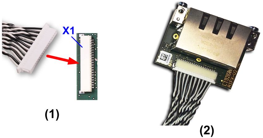
Introduction                                                                                                    4/62

1       Introduction

1.1      About the user manual
                          This user manual for your PC card CIFX M223090AE-RE\F Real-Time-
                          Ethernet informs you about the topics:
                          ·   Hardware description,
                          ·   installing the hardware and
                          ·   firmware download.
                          Further information on how to download the firmware, as well as
                          descriptions about configuration and diagnosis of your device can be found
                          in separate operating instruction manuals.

1.2      List of revisions
Index     Date        Changes
1         19-11-26    Manual created.
2         20-06-08    Sections System Requirements [} page 15] and Hints for problem solving [} page 21] text
                      corrections added.
                      Section System Requirements [} page 15] description updated.
                      Section PROFINET IO-Device [} page 43] description updated.
                      Section FCC compliance [} page 48] added.
                      Section References [} page 48] updated.
3         20-11-27    Section System LED [} page 24] updated.
                      Sections System Requirements [} page 15] and PC card CIFX M223090AE-RE\F [} page 36],
                      note on restriction for host systems updated.
4         21-02-25    Descriptions for Open Mode/TCP added to manual.
                      Sections Cable connector Ethernet X801, on CIFX M223090AE [} page 33] and cable
                      connector Ethernet X1, on AIFX-V2-RE added,
                      section EtherNet/IP Adapter (V3/5) [} page 27] updated.
                      Device Explorer details updated (with download of configuration).
                      Section Dimensions AIFX-V2-RE [} page 47], hight of PCB = 1.6 mm.
5         21-05-28    Section Basic card CIFX M223090AE [} page 6] and section Detached network interface
                      AIFX-V2-RE [} page 7] matrix label added.
                      Section System Requirements [} page 15] Note added (on ASIX Ax99100 RCB 128Bytes).
                      Section Hints for problem solving [} page 21] updated.
                      Section Cable connector Ethernet X801, on CIFX M223090AE [} page 33] revised,
                      sectionCable Connector Ethernet X1, on AIFX-V2-RE removed.
                      Section AIFX-V2-RE [} page 38], dimensions updated.
                      Section Dimensions CIFX M223090AE [} page 46], details on max. component height above
                      clarified.

                          Table 1: List of revisions

CIFX M223090AE-RE\F | Hardware description and installation                                   © Hilscher 2019 - 2021
DOC190704UM05EN | Revision 5 | English | 2021-05 | Released | Public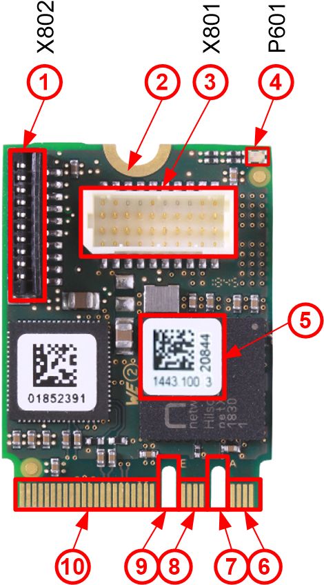
Devices and accessories                                                                                        5/62

2     Devices and accessories
                          The PC card CIFX M223090AE-RE\F is a Hilscher communication interface
                          based on the netX 90 communication controller and consists of a basic card
                          and a detached network interface.
                           PC card                 Description of the basic card                Accessories
                           CIFX M223090AE-RE\F     Communication Interface                      Detached network
                                                   M.2 2230 Key A+E: CIFX M223090AE             interface Ethernet:
                                                   Type (according to PCI Express M.2           AIFX-V2-RE
                                                   Specification):
                                                   2230 (=22x30 mm),
                                                   Keys: A and E
                                                   PCI Express slot (3.3 V),
                                                   for M.2 type 2230-D3, Dual Key A-E
                                                   (Socket 1 Connectivity)
                          Table 2: PC card CIFX M223090AE-RE\F
                           Product family    Card format and size       netX Key        Network and cable
                           CIFX              M 2230                     90     AE       -RE\F
                          Table 3: Meaning of the device name

                          The use refers exclusively to Slave systems. Depending on the loaded
                          firmware, the PC card cifX performs the protocol-specific communication of
                          the selected Real-Time Ethernet system. Data is exchanged between the
                          connected Ethernet devices and the PC or connecting device via the dual-
                          port memory.

CIFX M223090AE-RE\F | Hardware description and installation                                © Hilscher 2019 - 2021
DOC190704UM05EN | Revision 5 | English | 2021-05 | Released | Public
Devices and accessories 6/62
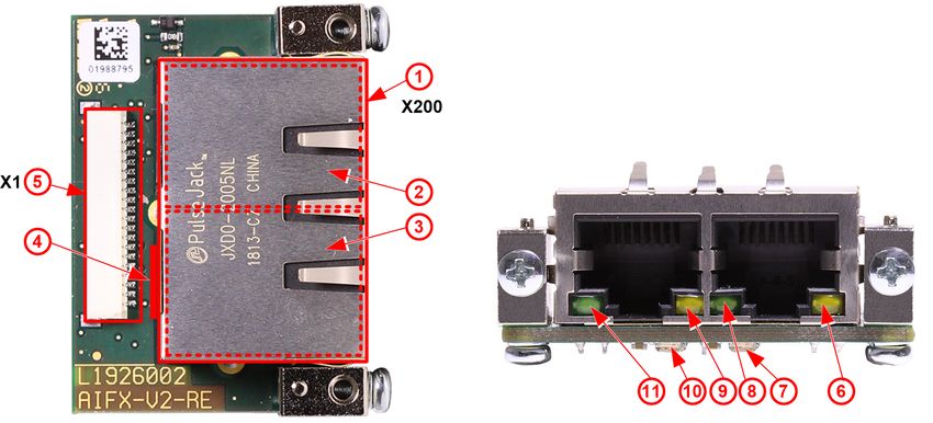
2.1 Basic card CIFX M223090AE
In the following illustration with legend you can recognize the device
elements significant for installation and operation each by a number.
Figure 1: Basic card CIFX M223090AE (revision 3)
No. Description
(1) Cable connector fieldbus (X802, 10 pin)
(2) Hole (with ground contact) for mounting the PC card
(3) Cable connector Ethernet (X801, 20 pin)
(4) System LED (yellow/green)
(5) Matrix label
(6) PCI Express M.2 bus, pin 1 to pin 7
(7) PCI Express M.2 bus, pin 8 to pin 15 (key A)
(8) PCI Express M.2 bus, pin 16 to pin 23
(9) PCI Express M.2 bus, pin 24 to pin 31 (key E)
(10) PCI Express M.2 bus, pin 32 to pin 75
Table 4: Legend on the basic card CIFX M223090AE
CIFX M223090AE-RE\F | Hardware description and installation © Hilscher 2019 - 2021
DOC190704UM05EN | Revision 5 | English | 2021-05 | Released | PublicDevices and accessories 7/62
2.2 Detached network interface AIFX-V2-RE
Figure 2: Detached network interface AIFX-V2-RE (revision 2)
No. Description
(1) 2 x Ethernet RJ45 socket connector (X200)
(2) Channel 1 (CH1)
(3) Channel 0 (CH0)
(4) Mini matrix label (reverse side X200)
(5) Cable connector Ethernet (X1, 20 pin)
(6) Ethernet LED yellow, channel 1 (CH1)
(7) Communication status LED COM1 (red/green)
(8) Ethernet LED green, channel 1 (CH1)
(9) Ethernet LED yellow, channel 0 (CH0)
(10) Communication status LED COM0 (red/green)
(11) Ethernet LED green, channel 0 (CH0)
Table 5: Legend on the detached network interface AIFX-V2-RE
Important:
Note that the detached network interface Ethernet AIFX-V2-RE
especially is designed for netX 90-based devices and exclusively
works together with them.
In contrast, the detached network interface Ethernet AIFX-RE is
only suitable for netX 100-based devices.
CIFX M223090AE-RE\F | Hardware description and installation © Hilscher 2019 - 2021
DOC190704UM05EN | Revision 5 | English | 2021-05 | Released | PublicDevices and accessories 8/62
2.3 Product software
The necessary information and software for your product you can download
free of charge at the web link
https://kb.hilscher.com/display/CARDS/.
Ø Select the link for the current release of the Communication Solution
netX 90/4000 DVD.
After downloading, you can immediately start with commissioning and
configurating your device.
Ø Check our website regularly for software updates for your product.
2.4 Revision or version status of hardware and software
The hardware revisions listed below, as well as the driver, software and
firmware versions belong together functionally. If a hardware installation is
available, the driver and the firmware must be updated according to these
specifications.
Device name Description Part no. Hardware revision
CIFX M223090AE-RE\F Basic card CIFX M223090AE and AIFX-V2-RE 1443.101 -
CIFX M223090AE Communication Interface M.2 2230 Key A+E (basic card) 1443.100 3
AIFX-V2-RE Detached network interface Ethernet 2801.100 2
Table 6: Hardware revisions
Driver and software Name Version
Device driver cifX Device Driver 2.3 or higher
Software to download the firmware Device Explorer 1.3
Configuration software Communication Studio 1.0
Table 7: Driver and software versions
Protocol File name Firmware
version
EtherCAT Slave X090F001.nxi 5.1
EtherNet/IP Adapter X090H001.nxi 5.1
PROFINET IO-Device X090D001.nxi 5.1
Open Modbus/TCP X090L001.nxi 5.1
Table 8: Firmware version and file names for permitted protocols
Note:
Unless otherwise stated, the firmware version in this manual is the
same as the stack version.
CIFX M223090AE-RE\F | Hardware description and installation © Hilscher 2019 - 2021
DOC190704UM05EN | Revision 5 | English | 2021-05 | Released | PublicDevices and accessories 9/62
2.5 Device label with matrix code
You can identify your device by means of the device label.
Note:
The position of the device label on your device is indicated in the
device overview.
The device label consists of a matrix code and the information contained
therein in plain text.
The 2D code (Data Matrix Code) contains the following information:
Part number: 1234.567
Hardware revision: 1
Serial number: 20000
Figure 3: Example 2D label
CIFX M223090AE-RE\F | Hardware description and installation © Hilscher 2019 - 2021
DOC190704UM05EN | Revision 5 | English | 2021-05 | Released | PublicSafety 10/62
3 Safety
3.1 General note
The documentation in the form of a user manual, an operating instruction
manual or other manual types, as well as the accompanying texts have
been created for the use of the products by qualified personnel. When
using the products, all Safety Messages, Integrated Safety Messages,
Property Damage Messages and all valid legal regulations must be obeyed.
Technical knowledge is presumed. The user has to assure that all legal
regulations are obeyed.
3.2 Intended use
Depending on the loaded firmware, with the PC card CIFX M223090AE-RE
\F a corresponding Real-Time Ethernet system can be realized. Information
on the permissible Real-Time Ethernet systems can be found in the section
Revision or version status of hardware and software [} page 8].
3.3 Personnel qualification
The PC card may only be installed, configured, operated or uninstalled by
qualified personnel. Job-specific technical skills for people professionally
working with electricity must be present concerning the following topics:
· Safety and health at work
· Mounting and connecting of electrical equipment
· Measurement and Analysis of electrical functions and systems
· Evaluation of the safety of electrical systems and equipment
· Installing and configuring IT systems
CIFX M223090AE-RE\F | Hardware description and installation © Hilscher 2019 - 2021
DOC190704UM05EN | Revision 5 | English | 2021-05 | Released | PublicSafety 11/62
3.4 Safety messages
3.4.1 Electrical shock hazard
The danger of lethal electrical shock caused by parts with more than 50V
may occur if you open the PC cabinet to install your PC card.
· HAZARDOUS VOLTAGE is present inside of the PC or of the
connecting device, into which the PC card is integrated. Strictly obey to
all safety rules provided by the device’s manufacturer in the
documentation!
· First disconnect the power plug of the PC or of the connecting device,
before you open the cabinet.
· Make sure that the power supply is off at the PC or at the connecting
device.
· Open the PC cabinet and install or remove the PC card only after
disconnecting power.
3.4.2 Personal injury, device damage due to hot swap/hot plug
The PC card is not designed or intended for a hot-swap or hot-plug
connection. Performing hot-swap or hot-plug may pose a hazard to the PC
card, the system platform and the person performing the action.
CIFX M223090AE-RE\F | Hardware description and installation © Hilscher 2019 - 2021
DOC190704UM05EN | Revision 5 | English | 2021-05 | Released | PublicSafety 12/62
3.5 Property damage
3.5.1 Excessive supply voltage
The PC card may only be operated with the prescribed supply voltage,
which corresponds to the tolerances specified in this manual. The limits of
the permitted range must not be exceeded.
Device damage, malfunctions
· If the supply voltage is above the specified upper limit, this can lead to
serious damage to the PC card!
· If the supply voltage is below the specified lower limit, malfunctions of
the PC card may occur.
3.5.2 Excessive signaling voltage
All I/O signal pins on the PC card tolerate only the specified signal voltage,
as specified in this manual.
Device destruction
Operating your PC card at a signal voltage that exceeds the specified
signal voltage can cause serious damage to the PC card!
3.5.3 Electrostatically sensitive devices
This equipment is sensitive to electrostatic discharge which cause internal
damage and affect normal operation. Therefore adhere to the necessary
safety precautions for components that are vulnerable with electrostatic
discharge if you install or replace your device. Follow the guidelines listed
hereafter when you handle this equipment:
· Touch a grounded object to discharge potential static.
· Wear an approved grounding wriststrap.
· Do not touch connectors or pins on the PC card.
· Do not touch circuit components inside the equipment.
· If available, use a static-safe workstation.
· When not in use, store the equipment in appropriate static-safe
packaging.
CIFX M223090AE-RE\F | Hardware description and installation © Hilscher 2019 - 2021
DOC190704UM05EN | Revision 5 | English | 2021-05 | Released | PublicSafety 13/62
3.5.4 Power drop during write and delete accesses in the file system
The FAT file system in the netX firmware is subject to certain limitations in
its operation. Write and delete accesses in the file system (firmware
update, configuration download etc.) can destroy the FAT (File Allocation
Table) if the accesses cannot be completed if the power drops. Without a
proper FAT, a firmware may not be found and cannot be started.
Ø Make sure that the power supply of the device does not drop during
write and delete accesses in the file system (firmware update,
configuration download etc.).
3.5.5 Exceeding the maximum number of permitted write and delete
accesses
This device uses a serial flash chip to store remanent data such as
firmware storage, configuration storage, etc. This device allows a maximum
of 100,000 write/delete accesses that are sufficient for standard operation
of the device. However, writing/deleting the chip excessively (e.g. changing
the configuration or changing the name of station) leads to the maximum
number of permitted write/delete accesses being exceeded and to device
damage. For example, if the configuration is changed once an hour, the
maximum number is reached after 11.5 years. If the configuration is
changed even more frequently, for example once a minute, the maximum
number is reached after approx. 69 days.
Avoid exceeding the maximum permitted write/delete accesses by writing
too often.
3.6 Information and data security
Take all usual measures for information and data security, in particular, for
PC cards with Ethernet technology. Hilscher explicitly points out that a
device with access to a public network (Internet) must be installed behind a
firewall or only be accessible via a secure connection such as an encrypted
VPN connection. Otherwise, the integrity of the device, its data, the
application or system section is not safeguarded.
Hilscher cannot assume any warranty or liability for damage due to
neglected security measures or incorrect installation.
CIFX M223090AE-RE\F | Hardware description and installation © Hilscher 2019 - 2021
DOC190704UM05EN | Revision 5 | English | 2021-05 | Released | PublicSafety 14/62
3.7 Warnings
When installing your device, observe the following warnings on possible
personal injury, as well as the warnings on property damage.
Lethal Electrical Shock caused by parts with more than 50V!
HAZARDOUS VOLTAGE inside of the PC or of the connecting device.
Ø First disconnect the power plug of the PC or of the connecting device,
before you open the cabinet.
Ø Make sure that the power supply is off at the PC or at the connecting
device.
Personal injury, device damage due to hot swap/hot plug
The PC card is not designed or intended for a hot-swap or hot-plug
connection.
Performing hot-swap or hot-plug may pose a hazard to the PC card, the
system platform and the person performing the action.
Electrostatically sensitive devices
To prevent damage to the PC and PC card, make sure the PC card is
grounded through the connection plate and PC, and make sure you are
grounded when you install or uninstall the PC card.
CIFX M223090AE-RE\F | Hardware description and installation © Hilscher 2019 - 2021
DOC190704UM05EN | Revision 5 | English | 2021-05 | Released | PublicInstalling the hardware 15/62
4 Installing the hardware
4.1 System Requirements
In order to install your PC cards cifX, you need a PC or a connecting device
with a PCI Express M.2 slot (host interface) for mounting the PC card.
Host interface
PC card Type Supply voltage Current Signal voltage
(1) consumption (2) (3)
CIFX M223090AE-RE\F PCI Express slot (3.3 V), +3.3 VDC ±5 % Refer to section PC PCIe compatible
for M.2 type 2230-D3, card CIFX
Dual Key A-E M223090AE-RE
(Socket 1 Connectivity) \F [} page 36].
Table 9: Host interface requirements
Comments:
(1) Required or permissible supply voltage
(2) Typical current consumption at 3.3 V. The typical current consumption
depends on the type of PC card. To ensure compatibility between different
systems, it is recommended to supply a maximum of 1 A (at +3.3 VDC
±5%).
(3) Required or tolerated signal voltage at the I/O signal pins on the PCIe
bus of the PC card
Host system
The basic card CIFX M223090AE uses an ASIX Ax99100. Therefore the
PC card CIFX M223090AE can only be operated with a PCIe host
controller that supports access to the IO area of the card (IOBAR).
The ASIX Ax99100 bridge chip only supports "Read Completion
Boundary" (RCB) of 128 bytes.
To ensure proper communication, make sure that the connected
(upstream) device, usually the host processor, does not use 64 byte RCB.
If you are not sure how to set the RCB, contact Hilscher Support.
Mounting the basic card
In order to mount the basic card, the board on which the PCI Express slot is
located must have a corresponding mounting bolt for screwing the basic
card on. The dimension for positioning the mounting bolt can be taken from
the dimension drawing for the basic card provided in this manual.
Operating system
For Device Explorer or Communication Studio: Windows® 10
CIFX M223090AE-RE\F | Hardware description and installation © Hilscher 2019 - 2021
DOC190704UM05EN | Revision 5 | English | 2021-05 | Released | PublicInstalling the hardware 16/62
Component heights
· The component height on the upper side of the basic card CIFX
M223090AE is higher than the height of 1.5 mm specified by the
standard because the height of the cable connectors (Ethernet X801, or
fieldbus X802) including the cable is approx. 8.5 mm above the printed
circuit board.
· The component height on the bottom side of the basic card CIFX
M223090AE complies with the standard specifications.
Panel dimensioning
· Panel cut-outs and holes for mounting AIFX
To mount the detached network interface Ethernet, the required panel
cut-outs for the communication status LEDs and the Ethernet sockets
as well as the holes for mounting the AIFX must be provided on the
housing of the PC or connecting device.
Panel cut-outs The layout for the panel cut-outs must be sufficiently
dimensioned for:
· Two Ethernet RJ45 sockets (for channel 0 and channel 1),
see also data sheet MOD JACK - MJIM, section
References [} page 48].
· The two LEDs COM0 and COM1
Drill holes 2, at a distance of 37.0 mm
Further information The dimensions for the required panel cut-outs or the distance
between the holes can be taken from the dimension drawing of
the AIFX, see section Dimensions AIFX-V2-RE [} page 47].
Table 10: Panel cut-outs and holes for AIFX mounting
· Front panel width
When dimensioning the front panel, note the width of the front panel
specified in section AIFX-V2-RE [} page 38].
CIFX M223090AE-RE\F | Hardware description and installation © Hilscher 2019 - 2021
DOC190704UM05EN | Revision 5 | English | 2021-05 | Released | PublicInstalling the hardware 17/62
4.2 Requirements for operation
The following described requirements must be fulfilled when operating the
PC card.
Requirements Specification Refer to section
Hardware installation Operating the PC card CIFX M223090AE-RE\F requires -
proper connection of the detached network interface Ethernet
AIFX-V2-RE to the basic card.
Communication For the communication of a PC card (Slave), a Master device -
is required for the communication system used.
To configure the Master device you need the device
description file with the name for:
· EtherCAT Slave:
Hilscher CIFX RE NETX90 ECS.xml,
· EtherNet/IP Adapter:
HILSCHER CIFX-RE NETX90 EIS V1.1.EDS,
· and PROFINET IO-Device:
GSDML-V2.35-HILSCHER-CIFX NETX 90 RE
PNS-20200402.xml.
The settings in the used Master must match the settings in
the Slave.
Software installation cifX Device Driver as driver for the host interface (latest Revision or version status
version of the driver). of hardware and
Device Explorer as software for downloading or updating the software [} page 8] and
firmware and configuration, as well as for setting the device References [} page 48]
driver. (Documentation on drivers
and software)
Communication Studio for configuration and diagnosis of
netX 90-based devices.
Firmware download The user must select the firmware using the Device Explorer
software and download it to the PC card.
The firmware includes a communication protocol.
Parameter settings By use of the Communication Studio configuration software
the PC card must be parameterized.
Table 11: Requirements for operation
CIFX M223090AE-RE\F | Hardware description and installation © Hilscher 2019 - 2021
DOC190704UM05EN | Revision 5 | English | 2021-05 | Released | PublicInstalling the hardware 18/62
4.3 Overview installation and firmware download
Below you will find an overview of the steps to install the hardware, the
driver and the firmware for your PC card CIFX M223090AE-RE\F:
Step Description Furhter information
Downloading installation · Download the installation files from the Hilscher website for: Revision or version status
files - cifX Device Driver (latest version) of hardware and
- Device Explorer software [} page 8]
- Communication Studio
· Save the installation files on the local hard disk of your PC.
Install driver and software · Double-click the installation file to open the autostart menu.
· Start the installation from the start screen and follow the
instructions in the installation menu.
Install hardware · Take the protective measures and safety precautions for the Installing the
hardware installation. hardware [} page 19]
· Open the housing of the PC or connecting device.
· Insert the basic card into the PCI Express slot and attach the
basic card.
· Attach the detached network interface to the front panel of
the PC.
· Connect the detached network interface to the basic card.
· Close the housing of the PC or connecting device.
Firmware and confguration · Perform the firmware download according to the instructions Loading firmware and
download in the "Device Explorer" operating instruction manual. configuration in the
device or making an
The PC card cifX now is ready for operation and still must be
update [} page 20]
configured.
· Then download the configuration.
Table 12: Overview for installation and firmware download
Detailed descriptions of the installation and operation of the
software can be found in the respective operating instruction
manual, see section References [} page 48].
CIFX M223090AE-RE\F | Hardware description and installation © Hilscher 2019 - 2021
DOC190704UM05EN | Revision 5 | English | 2021-05 | Released | PublicInstalling the hardware 19/62
4.4 Installing the hardware
Install the PC card CIFX M223090AE-RE\F in your PC or connecting
device as described below.
1. Preparation
Note the requirements and prerequisites described in the sections System
Requirements [} page 15] and Requirements for operation [} page 17].
2. Protective measures and safety precautions
Lethal electrical shock caused by parts with more than
50V!
Ø Disconnect the power plug of the PC or of the connecting device.
Ø Make sure that the power supply is off at the PC or at the connecting
device.
Personal injury, device damage due to hot-plug/hot-swap
Ø Do not "plug" or "unplug" the PC card during operation.
Adhere to the necessary safety precautions for
components that are vulnerable with electrostatic discharge.
Ø Make sure that the device is grounded via the endplate and the PC, and
make sure that you are discharged when you install/uninstall the device.
Device damage due to over torquing of the mounting
screw
Ø Do not over torque the screw used to mount the basic card to the board
to prevent damage to the printed circuit board.
3. Installation
Ø Open the housing of the PC or connecting device.
Ø Insert the basic card into the PCI Express slot.
Ø Screw the basic card onto the board. Use the half-moon cutout hole at
the upper edge of the basic card. The ground contact via the screw
head must be guaranteed.
Ø First attach the detached network interface Ethernet AIFX-V2-RE to the
housing panel of the PC or connecting device.
Ø Then connect the detached network interface Ethernet AIFX-V2-RE to
the basic card.
Important:
Note that the detached network interface Ethernet AIFX-V2-RE
especially is designed for netX 90-based devices and exclusively
works together with them.
In contrast, the detached network interface Ethernet AIFX-RE is
only suitable for netX 100-based devices.
Ø For this purpose, first plug the cable into the Ethernet X1 cable
connector on the AIFX-V2-RE.
CIFX M223090AE-RE\F | Hardware description and installation © Hilscher 2019 - 2021
DOC190704UM05EN | Revision 5 | English | 2021-05 | Released | PublicInstalling the hardware 20/62
Figure 4: Connecting cable to the detached network interface Ethernet (AIFX-V2-RE)
Ø Then plug the cable into the cable connector Ethernet X801 on the
basic card.
Figure 5: Connecting cable to basic card, example CIFX M223090AE
Ø Close the housing of the PC or connecting device again.
4.5 Loading firmware and configuration in the device or making
an update
Ø Download the firmware from the Hilscher website and save the firmware
on the local hard disk of your PC.
Ø If necessary, transfer the configuration to the PC. You create the
configuration using a suitable configuration software.
Ø Use Device Explorer to load the firmware and configuration into the
device or update the firmware and configuration in your device.
Ø When downloading the firmware and configuration to your device or
when performing an update, follow the instructions in the "Device
Explorer" operating instruction manual.
For the "Device Explorer" operating instruction manual, see section
References [} page 48].
CIFX M223090AE-RE\F | Hardware description and installation © Hilscher 2019 - 2021
DOC190704UM05EN | Revision 5 | English | 2021-05 | Released | PublicInstalling the hardware 21/62
4.6 Hints for problem solving
In case of an error or malfunction during operation of your PC card cifX,
observe the following troubleshooting instructions:
General
Ø Check that the requirements for operation of the PC card are met
according to the information provided in this user manual.
SYS and COM status LEDs
You can troubleshoot the system by checking the behavior of the LEDs.
· The SYS LED (yellow/green) on the device indicates the general device
status and can be switched on, off or blinks.
· The LEDs COM0 (red/green) and COM1 (red/green) at the detached
network interface Ethernet indicate the status of the device
communication and may be switched on or off permanently or in
phases, flash or they blink cyclically or acyclically.
If the SYS LED lights static green and the COM0 LED lights static green or
"off" (or the COM LEDs behave as shown in the table below), the PC card
cifX is in the "in operation" state. The salve device is in the state of cyclic
communication with the connected master device. The communication
between the master device and the salve device runs without interference.
LED EtherCAT Slave EtherNet/IP Adapter Open Modbus/TCP PROFINET IO-Device
COM 0 RUN (green) MS (green) RUN (green) SF (off)
COM 1 ERR (off) NS (green) ERR (off) BF (off)
Table 13: Behaviour of the communication status LEDs in "in operation" status
Ethernet LEDs
Ø Check the status of the Ethernet LEDs (LINK or L/A) to see if there is a
connection to the Ethernet.
Cable
Ø Check that the pin assignment of the cable used to connect the PC card
(Slave) to the Master device is correct.
Detailed descriptions of the behavior of the LEDs can be found in
the chapter on LEDs in this manual. Information about the device
diagnostics and its functions can be found in the user manual of the
configuration software for your device.
CIFX M223090AE-RE\F | Hardware description and installation © Hilscher 2019 - 2021
DOC190704UM05EN | Revision 5 | English | 2021-05 | Released | PublicInstalling the hardware 22/62
4.7 Uninstalling the hardware
Uninstall the PC card CIFX M223090AE-RE\F from your PC or connecting
device as described below.
1. Protective measures and safety precautions
Lethal electrical shock caused by parts with more than
50V!
Ø Disconnect the power plug of the PC or of the connecting device.
Ø Make sure that the power supply is off at the PC or at the connecting
device.
Personal injury, device damage due to hot-plug/hot-swap
Ø Do not "plug" or "unplug" the PC card during operation.
Adhere to the necessary safety precautions for
components that are vulnerable with electrostatic discharge.
Ø Make sure that the device is grounded via the endplate and the PC, and
make sure that you are discharged when you install/uninstall the device.
2. Uninstallation
Ø Open the housing of the PC or connecting device.
Ø Demount the detached network interface Ethernet from the basic card.
Ø Therefore pull the cable out of the cable connector Ethernet X801 (on
the basic card), as well as out of the cable connector Ethernet X1 on the
AIFX-V2-RE.
Ø Loosen the screw by which the basic card is attached to the board.
Ø Remove the basic card from the PCI Express slot.
Ø Disconnect the detached network interface from the housing cover of
the PC or connecting device.
Ø Close the housing of the PC or connecting device again.
4.8 Disposal of waste electronic equipment
Important notes from the European Directive 2012/19/EU “Waste Electrical
and Electronic Equipment (WEEE)”
Waste electronic equipment
This product must not be treated as household waste.
This product must be disposed of at a designated waste electronic
equipment collecting point.
Waste electronic equipment may not be disposed of as household waste.
As a consumer, you are legally obliged to dispose of all waste electronic
equipment according to national and local regulations.
CIFX M223090AE-RE\F | Hardware description and installation © Hilscher 2019 - 2021
DOC190704UM05EN | Revision 5 | English | 2021-05 | Released | PublicDiagnosis with LEDs 23/62
5 Diagnosis with LEDs
5.1 Overview
Note:
The communication status and Ethernet LEDs at the device are
defined by the loaded firmware of the protocol.
LED EtherCAT Slave EtherNet/IP Open Modbus/TCP PROFINET IO
SYS system status SYS SYS SYS SYS
Yellow/green
COM 0 communication RUN green MS red/green RUN green SF Rot
status
COM 1 communication ERR red NS red/green ERR red BF red
status
Ethernet green L/A IN LINK LINK LINK
Ch0
yellow - ACT ACT RX/TX
Ethernet green L/A OUT LINK LINK LINK
Ch1
yellow - ACT ACT RX/TX
Table 14: LEDs Real-time Ethernet systems (Duo LEDs and Ethernet LEDs)
Category LED Designation Category LED Designation
System status SYS System status Ethernet LINK, L Link
Communication COM Communication ACT, A Activity
status status
RUN Run L/A IN Link/Activity Input
ERR Error L/A OUT Link/Activity Output
MS Module status RX/TX Receive/Transmit
NS Network status
SF System failure
BF Bus failure
Table 15: LED designations
CIFX M223090AE-RE\F | Hardware description and installation © Hilscher 2019 - 2021
DOC190704UM05EN | Revision 5 | English | 2021-05 | Released | PublicDiagnosis with LEDs 24/62
5.2 System LED
The system status LED SYS can assume the states described below.
LED Color State Description
SYS Duo-LED: yellow RDY / green RUN
(green) On The firmware is running.
(green) Blinking During the formatting of the file system
(yellow) On A system error has occurred.
(yellow)/ Blinking, Firmware crash, unrecoverable (an internal exception occurred that
3x yellow, cannot be handled)
(green) 3x green
(yellow)/ Blinking, 1 Hz Firmware update mode active: The firmware is idle and waiting for
the update file.
(green)
(yellow)/ Blinking, 4 Hz Firmware update mode active: A firmware update is being installed.
(green)
(gray) Off · No supply voltage: No supply voltage for the device or hardware
defect.
· During a firmware reset
Table 16: States of the SYS-LED
LED state Definition
Blinking The LED turns on and off in phases.
Blinking, The LED turns on and off, with a frequency of approx. 1 Hz:
3x yellow,
· 3x yellow "On" for 500 ms and "Off" for 500 ms and
3x green
· 3x green "On" for 500 ms and "Off" for 500 ms.
Blinking, The LED turns on in phases yellow or green, with a frequency of approx.:
yellow/green,
· 1 Hz: 1 x yellow "On" for 500 ms and 1 x green "On" for 500 ms,
1 Hz, 4 Hz
· 4 Hz: 1 x yellow "On" for 125 ms and 1 x green "On" for 125 ms.
Table 17: Definitions of the states of the SYS LED
CIFX M223090AE-RE\F | Hardware description and installation © Hilscher 2019 - 2021
DOC190704UM05EN | Revision 5 | English | 2021-05 | Released | PublicDiagnosis with LEDs 25/62
5.3 EtherCAT Slave
For the EtherCAT Slave protocol, the communication LEDs RUN and ERR
as well as the Ethernet LED L/A IN or L/A OUT can assume the states
described below. This description is valid from stack version V2.5 (V2).
Communication status EtherCAT Slave
LED Color State Description
RUN Duo LED red/green
Position in the device (off) Off INIT: The device is in INIT state.
overview: (10)
(green) Blinking PRE-OPERATIONAL: The device is in PRE-OPERATIONAL
(2.5 Hz) state.
(green) Single flash SAFE-OPERATIONAL: The device is in SAFE-OPERATIONAL
state.
(green) On OPERATIONAL: The device is in the OPERATIONAL state.
ERR Duo LED red/green
Position in the device (off) Off No error: The EtherCAT communication of the device is in
overview: (7) working condition.
(red) Blinking Invalid configuration: General Configuration Error
(2.5 Hz) Possible reason: State change commanded by master is
impossible due to register or object settings.
(red) Single flash Local error: Slave device application has changed the EtherCAT
state autonomously.
Possible reason 1: A host watchdog timeout has occurred.
Possible reason 2: Synchronization Error, device enters Safe-
Operational automatically.
(red) Double flash Application watchdog timeout: An application watchdog timeout
has occurred. Possible reason: Sync Manager Watchdog timeout.
Table 18: Communication status EtherCAT Slave
LED state Definition
Blinking The LED turns on and off with a frequency of 2.5 Hz: “On” for 200 ms,
(2.5 Hz) followed by “Off” for 200 ms.
Single flash The LED shows one short flash (200 ms) followed by a long “Off“ phase
(1,000 ms).
Double flash The LED shows a sequence of two short flashes (each 200 ms), separated
by a short "Off" phase (200 ms). The sequence is finished by a long "Off"
phase (1,000 ms).
Table 19: Definition LED states communication status
CIFX M223090AE-RE\F | Hardware description and installation © Hilscher 2019 - 2021
DOC190704UM05EN | Revision 5 | English | 2021-05 | Released | PublicDiagnosis with LEDs 26/62
Ethernet status EtherCAT Slave
LED Color State Description
L/A IN, L/A OUT LED green
Ch0: (11) , Ch1: (8) (green) On Link: The device is linked to the Ethernet, but does not send/
receive Ethernet frames.
(green) Flickering (load Activity: The device is linked to the Ethernet and sends/receives
dependent) Ethernet frames.
(off) Off The device has no link to the Ethernet.
Ch0: (9) , Ch1: (6) LED yellow
(off) Off This LED is not used.
Table 20: Ethernet status EtherCAT Slave
LED state Definition
Flickering The LED turns on and off with a frequency of approximately 10 Hz to
(load indicate high Ethernet activity: "On" for approximately 50 ms, followed by
dependent) "Off" for 50 ms. The LED turns on and off in irregular intervals to indicate low
Ethernet activity.
Table 21: Definition LED states Ethernet status
CIFX M223090AE-RE\F | Hardware description and installation © Hilscher 2019 - 2021
DOC190704UM05EN | Revision 5 | English | 2021-05 | Released | PublicDiagnosis with LEDs 27/62
5.4 EtherNet/IP Adapter (V3/5)
For the EtherNet/IP Adapter protocol, the communication LEDs MS and NS
as well as the Ethernet LEDs LINK and ACT can assume the states
described below. This description is valid from stack version V3.4 or from
V5.1.
Communication status EtherNet/IP Adapter
LED Color State Description
MS (module status) Duo LED red/green
Position in the device (green) On Device operational: The device is operating correctly.
overview: (10)
(green) Flashing (1 Hz) Standby: The device has not been configured.
Flashing fast Self-test: The device performs a self-test after power-on. The
(green/red/ green/red/ following sequence is displayed during the self-test:
green) green
· NS-LED off.
· MS LED turns green for approximately 250 ms, turns red for
approximately 250 ms, and again turns green (and holds
that state until the power-up test has completed).
· NS LED turns green for approximately 250 ms, turns red for
approximately 250 ms, and then turns off (and holds that
state until the power-up test has completed).
Flashing Flashing sequence: The flashing sequence is used to
(red/green/off) sequence red/ visually identify the device. The scanner can start the flashing
green/off sequence in Identity object 1 of the device. The MS LED and
NS LED perform the flashing sequence simultaneously.
(red) Flashing (1 Hz) Major recoverable fault: The device has detected a major
recoverable fault. E.g., an incorrect or inconsistent
configuration can be considered a major recoverable fault.
(red) On Major unrecoverable fault: The device has detected a major
unrecoverable fault.
(off) Off No power: The device is powered off.
NS Duo LED red/green
(Network status) On Connected: An IP address is configured, at least one CIP
(green)
Position in the device connection (any transport class) is established, and an
overview: (7) Exclusive Owner connection has not timed out.
(green) Flashing (1 Hz) No connections: An IP address is configured, but no CIP
connections are established, and an Exclusive Owner
connection has not timed out.
Flashing fast Self-test: The device performs a self-test after power-on.
(green/red/ green/red/ Refer to the description of the MS LED in the self-test status.
green) green
Flashing Flashing sequence: The flashing sequence is used to
(red/green/off) sequence red/ visually identify the device. The scanner can start the flashing
green/off sequence in Identity object 1 of the device. The MS LED and
NS LED perform the flashing sequence simultaneously.
(red) Flashing (1 Hz) Connection timeout: An IP address is configured, and an
Exclusive Owner connection for which this device is the target
has timed out.
The NS LED returns to steady green only when all timed out
Exclusive Owner connections are reestablished.
(red) On Duplicate IP: The device has detected that its IP address is
already in use.
(off) Off Not powered, no IP address: The device does not have an
IP address (or is powered off).
Table 22: Communication status EtherNet/IP Adapter
CIFX M223090AE-RE\F | Hardware description and installation © Hilscher 2019 - 2021
DOC190704UM05EN | Revision 5 | English | 2021-05 | Released | PublicDiagnosis with LEDs 28/62
LED state Definition
Flashing (1 Hz) The LED turns on and off with a frequency of 1 Hz: “On” for 500 ms,
followed by “Off” for 500 ms.
Flashing fast The MS LED or NS LED turns on green "On" for 250 ms, then red "On" for
green/red/ 250 ms, then green "On" (until the test is completed).
green
Flashing The MS LED and NS LED each turn red "On" for 500 ms, then green "On"
sequence red/ for 500 ms, then "Off" for 500 ms. This flashing sequence is repeated at
green/off least 6 times.
Table 23: Definition LED states communication status
Ethernet status EtherNet/IP Adapter
LED Color State Description
LINK LED green
Ch0: (11) , Ch1: (8) (green) On The device is linked to the Ethernet.
(off) Off The device has no link to the Ethernet.
ACT LED yellow
Ch0: (9) , Ch1: (6) (yellow) Flickering (load The device sends/receives Ethernet frames.
dependent)
(off) Off The device does not send/receive Ethernet frames.
Table 24: Ethernet status EtherNet/IP Adapter
LED state Definition
Flickering The LED turns on and off with a frequency of approximately 10 Hz to
(load indicate high Ethernet activity: "On" for approximately 50 ms, followed by
dependent) "Off" for 50 ms. The LED turns on and off in irregular intervals to indicate
low Ethernet activity
Table 25: Definition LED states Ethernet status
CIFX M223090AE-RE\F | Hardware description and installation © Hilscher 2019 - 2021
DOC190704UM05EN | Revision 5 | English | 2021-05 | Released | PublicDiagnosis with LEDs 29/62
5.5 OpenModbusTCP
For the OpenModbusTCP protocol, the communication LEDs RUN and
ERR as well as the Ethernet LEDs LINK and ACT can assume the states
described below. This description is valid from stack version V0.9.
Communication status OpenModbusTCP
LED Color State Description
RUN Duo LED red/green
Position in the device (green) On Connected: OMB task has communication. At least one TCP
overview: (10) connection is established.
(green) Flashing Ready, not configured yet: OMB task is ready and not yet
(1 Hz) configured.
(green) Flashing Waiting for Communication: OMB task is configured.
(5 Hz)
(off) Off Not Ready: OMB task is not ready.
ERR Duo LED red/green
Position in the device (off) Off No communication error
overview: (7)
(red) Flashing System error
(2 Hz, 25% on)
(red) On Communication error active
Table 26: Communication status OpenModbusTCP
LED state Definition
Flashing The LED turns on and off with a frequency of
(1 Hz) 1 Hz: "On" for 500 ms, followed by "Off" for 500 ms.
Flashing The LED turns on and off with a frequency of
(5 Hz) 5 Hz: “On” for 100 ms, followed by “Off” for 100 ms.
Flashing The LED turns on and off with a frequency of
(2 Hz, 2 Hz: “On” for 125 ms, followed by “Off” for 375 ms.
25% on)
Table 27: Definition LED states communication status
Ethernet status OpenModbusTCP
LED Color State Description
LINK LED green
Ch0: (11) , Ch1: (8) (green) On The device is linked to the Ethernet.
(off) Off The device has no link to the Ethernet.
ACT LED yellow
Ch0: (9) , Ch1: (6) Flickering (load The device sends/receives Ethernet frames.
(yellow) dependent)
(off) Off The device does not send/receive Ethernet frames.
Table 28: Ethernet status OpenModbusTCP
LED state Definition
Flickering The LED turns on and off with a frequency of approximately 10 Hz to
(load indicate high Ethernet activity: "On" for approximately 50 ms, followed by
dependent) "Off" for 50 ms. The LED turns on and off in irregular intervals to indicate low
Ethernet activity.
Table 29: Definition LED states Ethernet status
CIFX M223090AE-RE\F | Hardware description and installation © Hilscher 2019 - 2021
DOC190704UM05EN | Revision 5 | English | 2021-05 | Released | PublicDiagnosis with LEDs 30/62
5.6 PROFINET IO-Device
For the PROFINET IO-Device protocol, the communication LEDs SF (system
failure) and BF (bus failure) as well as the Ethernet LEDs LINK and RX/TX
can assume the states described below. This description is valid from stack
version V3.x (V3).
Communication status PROFINET IO-Device
LED Color State Description
SF (System Failure) Duo LED red/green
Position in the device (off) Off No error
overview: (10)
(red) Flashing DCP signal service is initiated via the bus.
(1 Hz, 3 s)
(red) On Watchdog timeout; channel, generic or extended diagnosis
present; system error
BF (Bus Failure) Duo LED red/green
Position in the device (off) Off No error
overview: (7)
(red) Flashing No data exchange
(2 Hz)
(red) On No configuration;
or low speed physical link; or no physical link
Table 30: Communication status PROFINET IO-Device
LED state Definition
Flashing The LED turns on and off for 3 seconds with a frequency of 1 Hz: “On” for
(1 Hz, 3 s) 500 ms, followed by “Off” for 500 ms.
Flashing The LED turns on and off with a frequency of
(2 Hz) 2 Hz: “On” for 250 ms, followed by “Off” for 250 ms.
Table 31: Definition LED states communication status
Ethernet status PROFINET IO-Device
LED Color State Description
LINK LED green
Ch0: (11) , Ch1: (8) (green) On The device is linked to the Ethernet.
(off) Off The device has no link to the Ethernet.
RX/TX LED yellow
Ch0: (9) , Ch1: (6) (yellow) Flickering The device sends/receives Ethernet frames.
(load
dependent)
(off) Off The device does not send/receive Ethernet frames.
Table 32: Ethernet status PROFINET IO-Device
LED state Definition
Flickering The LED turns on and off with a frequency of approximately 10 Hz to
(load indicate high Ethernet activity: "On" for approximately 50 ms, followed by
dependent) "Off" for 50 ms. The LED turns on and off in irregular intervals to indicate low
Ethernet activity.
Table 33: Definition LED states Ethernet status
CIFX M223090AE-RE\F | Hardware description and installation © Hilscher 2019 - 2021
DOC190704UM05EN | Revision 5 | English | 2021-05 | Released | PublicConnectors 31/62
6 Connectors
6.1 Ethernet RJ45 socket
100BASE-TX and 10BASE-T
Note:
The device supports the Auto-Crossover function causing RX and
TX to be exchanged where appropriate. The following figure shows
the RJ45 standard pin assignment.
Figure 6: Ethernet pin assignment at the RJ45 socket
Pin Signal Meaning
1 TX+ Transmit data positive channel
2 TX- Transmit data negative channel
3 RX+ Receive data positive channel
4 Term 1 Bridged and terminated to PE via RC link*
5 Term 1
6 RX- Received data negative channel
7 Term 2 Bridged and terminated to PE via RC link*
8 Term 2
*Bob Smith Termination
Table 34: Ethernet pin assignment at the RJ45 socket
Note:
The RJ45 connector may only be used for LAN, not for
telecommunications connections.
CIFX M223090AE-RE\F | Hardware description and installation © Hilscher 2019 - 2021
DOC190704UM05EN | Revision 5 | English | 2021-05 | Released | PublicConnectors 32/62
6.2 Data of the Ethernet connection
For the Ethernet interface use RJ45 plugs and twisted pair cable of category
5 (CAT5) or higher, which consists of 4 twisted cores and has a maximum
transfer rate of 100 MBit/s (CAT5).
100BASE-TX and 10BASE-T
Medium 2 x 2 twisted pair copper cables, CAT5 (100 MBit/s)
Length of cable Max. 100 m
Transfer rate 10 MBit/s/100 MBit/s
Table 35: Ethernet connection data 100BASE-TX and 10BASE-T
6.3 Usability of hubs and switches
The use of hubs or switches is prohibited or permitted for the respective
communication systems. The following table shows the usability of hubs
and switches for each communication system:
Communication Hub Switch
system
EtherCAT Forbidden Only permitted between EtherCAT Master and first
EtherCAT Slave (100 MBit/s, Full Duplex)
EtherNet/IP Allowed Allowed (10 MBit/s/100 MBit/s, full or half duplex, auto
negotiation)
Open Modbus/TCP Allowed Allowed (10 MBit/s/100 MBit/s, full or half duplex, auto
negotiation)
PROFINET IO Forbidden Only allowed if switch supports priority tagging and
LLDP (100 MBit/s, full duplex)
Table 36: Usability of hubs and switches
CIFX M223090AE-RE\F | Hardware description and installation © Hilscher 2019 - 2021
DOC190704UM05EN | Revision 5 | English | 2021-05 | Released | PublicYou can also read