SECTION LS TYRES, RIMS, SUSPENSION AND STEERING - NATIONAL CODE OF PRACTICE LIGHT VEHICLE CONSTRUCTION MODIFICATION - VERSION 2.0 JANUARY 2011 ...
←
→
Page content transcription
If your browser does not render page correctly, please read the page content below
NATIONAL CODE OF PRACTICE
           for
LIGHT VEHICLE CONSTRUCTION
           and
       MODIFICATION

       SECTION LS
TYRES, RIMS, SUSPENSION
     AND STEERING

 VERSION 2.0 JANUARY 2011
Section LS Tyres, Rims, Suspension and Steering

                                Vehicle Standards Bulletin 14

National Code of Practice for Light Vehicle Construction and Modification (VSB 14)

    Important Information for Users

    Users of VSB 14 need to be aware that this document needs to be used in conjunction with the
    appropriate administrative requirements of the jurisdiction in which they wish to either register a
    vehicle or to obtain approval for a modification for an already registered vehicle. Administrative
    requirements include, amongst other things, processes for vehicle registration, obtaining
    exemptions, obtaining modification approvals, vehicle inspections, preparation and submission of
    reports and the payment of appropriate fees and charges.

    If unsure of any of the requirements specified in VSB 14, or if more information is needed for any
    other issues concerning the administrative requirements, users should contact their relevant
    Registration Authority prior to commencing any work.

    While VSB 14 provides advice on the construction of Individually Constructed Vehicles (ICVs)
    and the execution of modifications, it is not to be taken to be a design manual. Determination of
    component strength, performance, suitability and functionality must be either calculated or
    determined on a case by case basis by suitably qualified personnel experienced in each matter
    under consideration.

    Users of VSB 14 also need to ensure that they refer to the most recent version of the relevant
    Section/s when working on a project. The version is identified by the version number and date on
    the face page of each Section. The version and date is also located in the footer of each page in
    each Section. On the website the version number is specified in the Section file name for easy
    identification.

    If a project is taking a long time to complete, check the currency of the version you are using.

    Users must be familiar with the provisions stated in the Preface and Introduction. These two
    Sections provide the necessary background information to assist users in understanding how
    VSB 14 is administered by Registration Authorities across Australia, on how it is structured, and
    the meaning of the types of modification codes specified in VSB 14. If not already done so, users
    should download them for study and reference.

    Understanding these requirements is important to ensure that the correct processes are followed
    thereby reducing the likelihood of having work rejected by Registration Authorities.

    Many of the Sections refer to other Sections within VSB 14 for further information or additional
    requirements. Users must read and apply all relevant Sections.

    If in doubt about any issue concerning or contained in VSB 14, users should seek clarification
    from the appropriate state or territory Registration Authority.

    Please do not contact Vehicle Safety Standards (VSS) of the Australian Government
    Department of Infrastructure and Transport in Canberra about VSB 14. VSS provides the
    website as a service only.

Version 2.0 – 1 January 2011                                                            Page 2/LS74
Section LS Tyres, Rims, Suspension and Steering
CONTENTS
1 Scope 6
1.1 Basic Modifications Not Requiring Certification 6
1.2 Modifications Requiring Certification under Section LS 6
1.3 Modifications Not Covered Under Section LS 6
General Requirements 7
2.1 Driveability 7
2.2 Strength and Flexibility 9
2
2.3 Fabrication 9
2.4 Suspension and Steering Terminology 11
2.5 Relevant Publications 15
2.6 Modifications to Vehicles Equipped with ESC 15
2.7 Safety Issues Associated with Raising or Lowering a Vehicle 16
3 Australian Design Rules 18
4 Basic Modifications Without Certification 19
Replacement Tyres on Standard (or Manufacturer’s Optional)
4.1 19
Rims
4.2 Non-standard Tyres and Rims 19
Replacement Tyres and Rims on Vehicles with Modified Axles,
4.3 26
Suspension and/or Steering
4.4 Shock Absorbers 26
4.5 Sway Bars 26
4.6 Track Rods 26
4.7 Strut Braces 26
4.8 Power Steering 26
4.9 Steering Wheels 26
4.10 Rose or Heim Joints 27
4.11 Lowering or Raising Vehicles 28
5 Certified Modifications (LS Codes) 30
LS1 LHD Vehicle Steering Conversion (Design) 31
Checklist 34
Version 2.0 – 1 January 2011 Page 3/LS74Section LS Tyres, Rims, Suspension and Steering
LS2 LHD Vehicle Steering Conversion 39
Checklist 40
LS3 Front Suspension and Steering Modification (Design) 44
Checklist 55
LS4 Front Suspension and Steering Modification 62
Checklist 63
LS5 Rear Suspension Modification (Design) 66
Checklist 69
LS6 Rear Suspension Modification 71
Checklist 72
Version 2.0 – 1 January 2011 Page 4/LS74Section LS Tyres, Rims, Suspension and Steering
Document Amendments by Version
Version Amendments
Version 2
Published 1 January 2011
Clause 2.6 added advising that modifications to
vehicles equipped with ESC have certain
requirements.
Reference to commercial vehicles replaced with
goods vehicle.
The allowable wheel track increase of all off-road
four wheel drive vehicles and goods vehicles (ADR
category MC, NA, NB) has now been increased to
no more than 50mm beyond the maximum specified
by the vehicle manufacturer for the particular model.
This document has also a number of editorial
amendments that have had no affect on its technical
content.
Version 2.0 – 1 January 2011 Page 5/LS74Section LS Tyres, Rims, Suspension and Steering
1 SCOPE
This Section outlines the minimum design, installation and fabrication requirements for the
following light vehicle modifications involving tyres, rims, suspension and steering.
1.1 BASIC MODIFICATIONS NOT REQUIRING CERTIFICATION
The following modifications may be performed without certification if they are carried out in
accordance with sub-section 2 General Requirements and the total change in vehicle height
resulting from all modifications performed, does not exceed 50mm.
Note: In NSW, although vehicles whose height has been changed up to 50mm do not
require certification by an engineering signatory, the registration authority must be
notified of the modification.
• Tyre and rim substitution carried out within the limits specified in this Section;
• Lowering and raising suspensions (by not more than one third of the original
suspension travel provided the original vehicle height is not increased or decreased by
more than 50mm);
• Raising the vehicle with a body lift kit provided the original vehicle height is not
increased by more than 50mm (refer to sub-section 4.11 for conditions and limitations);
• Shock absorber substitution;
• Spring and sway bar substitution;
• Track rod and strut brace installation;
• Steering wheel substitution (refer to sub-section 4.9 of this Section); and
• Power steering (manufacturer’s option) conversion.
1.2 MODIFICATIONS REQUIRING CERTIFICATION UNDER SECTION LS
The following modifications require certification under the LS Codes;
• Left to right hand drive steering conversions;
• Steering and suspension modifications;
• Power steering (non-standard) conversion;
• Rack and pinion steering conversion;
• Suspension strut or upright substitution;
• Rear axle substitution; and
• Raising the vehicle beyond 50mm but not more than 150mm.
1.3 MODIFICATIONS NOT COVERED UNDER SECTION LS
The following modifications are not covered under Section LS, nor by any other Section of
VSB 14.
Version 2.0 – 1 January 2011 Page 6/LS74Section LS Tyres, Rims, Suspension and Steering
• Vehicle lifts that exceed 150mm: Raising vehicles beyond 150mm is not covered
under this Code of Practice.
• Vehicle Lifts to any Vehicle that has had its track reduced: Vehicles that have had a
track reduction will need to be assessed on a case-by-case basis.
• Remote Steering Systems: Steering systems that operate without complete
mechanical connection (such as hydraulic or electric actuation) are not covered in this
Code of Practice.
• Steering Wheels Fitted with Integral Airbags: VSB 14 does not cover steering
wheels fitted with air bags.
• Installation of Variable Air or Hydraulic Suspension Systems: Installation of non-
original suspension systems that allow the ride-height of the vehicle to be varied by the
driver are not covered under this Code of Practice.
• Modifications to Vehicles fitted with Electronic Stability Control (ESC): These
vehicles have limitations on the modifications covered by Section LS – refer to Clause
2.6 for further details.
2 GENERAL REQUIREMENTS
This sub-section applies to all light vehicles and must be read and applied in conjunction with all
the LS Codes applicable to the proposed modifications.
Modified vehicles must continue to comply with the Australian Design Rules (ADRs) to which
they were originally constructed, except as allowed for in the Australian Vehicle Standards
Rules (AVSR). These modified vehicles must also comply with the applicable in-service
requirements of the AVSR.
Modified pre-ADR vehicles must continue to comply with the AVSR.
Compliance with the AVSR also means compliance with the equivalent regulations of a State or
Territory of Australia.
The use of the word wheel means the tyre and rim combination.
2.1 DRIVEABILITY
Driveability in this context means that when driven on the road the vehicle responds to the
drivers inputs without any dangerous or undesirable reactions and meets the turning and
clearance requirements of the AVSR.
Owners wishing to alter the appearance and/or road handling characteristics of their vehicles
often alter suspensions and fit tyres and rims different from the original manufacturer’s
specifications. Some changes can achieve improvements in cornering stability, but other
changes, including unsuitable tyre and rim selection can lead to dangerous situations. The
following should be considered:
2.1.1 Steering Behaviour
Fitting wider rims and tyres usually involves altering the steering scrub radius. This can result in
unpredictable steering response characteristics.
Version 2.0 – 1 January 2011 Page 7/LS74Section LS Tyres, Rims, Suspension and Steering
Tyres contacting body and suspension components can reduce the vehicle’s turning circle.
2.1.2 Roadholding and Handling
The roadholding and handling qualities of a modified vehicle must not be adversely affected.
2.1.3 Braking Behaviour
Some non-standard rims and tyres fitted to cars with diagonally split braking systems can cause
reduced directional stability in the event of brake failure. Larger diameter tyres also require
greater pedal pressure to achieve the same braking distances.
2.1.4 Ground Clearance and Running Clearance
Ground clearance, of a vehicle, means the minimum distance to the ground from a point on the
underside of the vehicle, except a point on a tyre, wheel, wheel hub, brake backing plate or
flexible mudguard or mudflap of the vehicle.
Running clearance, of a vehicle, means the distance from the surface on which an unladen
vehicle is standing to the lowest point on the vehicle excluding unsprung mass.
Vehicles built to comply with the Third Edition ADRs must comply with the ground clearance
requirements of ADR 43/…. Vehicles built to comply with ADR 43/04 must also comply with the
running clearance requirements.
All other motor vehicles with more than 3 wheels must have a ground clearance of:
• at least 100mm at any point within 1 metre of an axle; and
• at least one-thirtieth of the distance between the centres of adjacent axles at the
midpoint between them (refer Figure LS1); and
• at any other point — at least the distance that allows the vehicle to pass over a peak in
the road with a gradient on either side of 1:15, if the wheels of 1 axle of the vehicle are
on the slope on one side of the peak and the wheels of the next axle are on the slope
on the other side.
Figure LS1 Measuring Ground Clearance
2.1.5 Turning Circle
The vehicle must have a sufficient turning circle in each direction and must meet all ADR
dimensional requirements.
Version 2.0 – 1 January 2011 Page 8/LS74Section LS Tyres, Rims, Suspension and Steering
2.1.6 Tyre Deflation
Any modifications to suspension and steering, including replacement tyres and rims, must
ensure that the vehicle’s body, exhaust system, axles, suspension or steering components do
not contact the road when tyre(s) deflate. Therefore, if one or more tyres deflate when the
vehicle is on a level road, the rims and tyres must be the only part of the vehicle in contact with
the road.
2.1.7 Ride Height
Ride height is a very important parameter as it has a direct influence on a vehicle’s centre of
mass (centre of gravity) and hence its stability and performance.
2.1.8 Suspension Travel
It is important to retain at least two thirds of the original suspension travel in either direction in
order to maintain safe road holding characteristics.
2.2 STRENGTH AND FLEXIBILITY
When replacing wheels and tyres, and modifying suspension and steering components,
consideration should be given to the following:
2.2.1 Strength of Suspension and Steering Components
Changes in wheel width and offset, and bump clearance can cause significant increases in
stress levels in suspension and steering components of both independent and beam axle
suspensions.
2.2.2 Fatigue Strength
Some modifications that are satisfactory in the short term (e.g. on competition cars that travel
relatively short distances) are often completely unsuitable for road use because of the effects of
metal fatigue. A suspension component on a road car can break from metal fatigue at stresses
much less than that experienced during competition use.
2.2.3 Flexible Arms and Joints
Some suspension components (flexible arms and joints) are designed to twist when the
suspension moves vertically. Boxing-in these components and/or using stiffer replacement
bushes can cause large stresses in mounting bolts and brackets causing them to break or tear
out. It is recommended that replacement of rubber flexing bushes with harder bushes should
only be done in applications where single plane movement occurs.
2.3 FABRICATION
All work must be performed in accordance with recognised engineering standards. Cutting,
heating, welding or bending of components should be avoided by choosing unmodified
production components wherever possible.
2.3.1 Welding, Fasteners and Electroplating
Mandatory requirements and guidance on the above items are contained in Section
LZ Appendices.
• For the use of fasteners refer to Appendix A Fasteners;
Version 2.0 – 1 January 2011 Page 9/LS74Section LS Tyres, Rims, Suspension and Steering
• For welding techniques and procedures refer to Appendix C Heating and Welding of
Steering Components; and
• For electroplating refer to Appendix D Electroplating.
2.3.2 Mating Parts
Standard features such as splines, tapers and keyways must conform to published standards
and their mating parts must conform to matching standards.
Version 2.0 – 1 January 2011 Page 10/LS74Section LS Tyres, Rims, Suspension and Steering
2.4 SUSPENSION AND STEERING TERMINOLOGY
Figures LS2, LS3, LS4, LS5 and LS6 diagrammatically illustrate the common terminology used
in suspension and steering systems.
Figure LS2 Typical Steering and Suspension Systems
Version 2.0 – 1 January 2011 Page 11/LS74Section LS Tyres, Rims, Suspension and Steering
Figure LS3 Typical Steering and Suspension Systems
Version 2.0 – 1 January 2011 Page 12/LS74Section LS Tyres, Rims, Suspension and Steering
Figure LS4 Rear Suspension Systems
Version 2.0 – 1 January 2011 Page 13/LS74Section LS Tyres, Rims, Suspension and Steering
Figure LS5 Front Wheel Drive Steering Geometry
Figure LS6 Rim Offset
Version 2.0 – 1 January 2011 Page 14/LS74Section LS Tyres, Rims, Suspension and Steering
2.5 RELEVANT PUBLICATIONS
The following publications provide background information relating to the types of modifications
covered in this Section:
• Automotive Suspensions – Campbell, Colin – ISBN 412-16420-5;
• Vehicle System Components Design and Safety – Limpert, Rudolf -
ISBN 0-471-08133-7;
• Automotive Suspensions Steering Alignment and Brakes – Billiet, Walter and Alley,
Walter – ISBN 0-8269-0122-2; and
• Theory and Practice of Chassis Tuning – Norbye, Jan – ISBN 0-85113-076-3.
2.6 MODIFICATIONS TO VEHICLES EQUIPPED WITH ESC
Many modern vehicles are now being equipped with a safety feature known as Electronic
Stability Control (ESC). (ESC is also known by other terms including Vehicle Stability Control or
Dynamic Stability Control).
ESC provides motorists additional safety in terms of vehicle stability and handling, particularly in
difficult situations where loss of control could otherwise occur. ESC uses computer technology
to assist the driver in maintaining control in emergency situations – particularly when executing
avoidance manoeuvres involving sudden swerving and in cases when the vehicle begins to
slide and rotate sideways.
Braking is automatically applied to individual wheels, such as the outer front wheel to counter
oversteer, or the inner rear wheel to counter understeer. Some ESC systems also reduce
engine power until steering control is regained.
ESC is programmed by the vehicle manufacturer for the vehicle to which it is fitted taking into
account a number of design parameters such as brake, engine and transmission performance,
tyre specifications, steering systems, suspension (type and performance characteristics), mass
of the vehicle and weight distribution.
For modification codes contained in this Section of VSB 14, evidence should be obtained either
from the vehicle manufacturer or through testing to determine the impact on the ESC system.
To remain within the scope of this Section of VSB 14, a vehicle fitted with ESC must not be
modified if the operation of the ESC is affected unless the ESC system is adjusted accordingly.
Persons wishing to modify vehicles equipped with ESC must contact their Registration
Authority for further information and guidance.
Version 2.0 – 1 January 2011 Page 15/LS74Section LS Tyres, Rims, Suspension and Steering
2.7 SAFETY ISSUES ASSOCIATED WITH RAISING OR LOWERING A VEHICLE
Modifying a vehicle’s suspension by raising or lowering it has the potential to decrease its safety
by compromising its handling and braking performance, affecting safety features, and by
altering the position of impact-absorbing sections.
The safety of raised or lowered vehicles may be reduced in the following areas:
• Dynamic stability – Raising a vehicle correspondingly raises its centre of gravity,
which increases its propensity to overturn;
• Road handling capabilities – In addition to the above, raising a vehicle’s centre of
gravity adversely affects its ability to manoeuvre, such as changing lanes and
cornering;
• Electronic stability control (ESC) – ESC is an important safety feature that helps a
driver retain control of a vehicle under extreme driving circumstances, such as those
experienced during emergency avoidance manoeuvres. ESC is specifically
programmed by the manufacturer for a vehicle’s particular configuration. Altering the
ride height could affect this programming and detrimentally affect the benefits of ESC;
• Braking characteristics* - Altering a vehicle’s ride height by changing the tyres or
rims can affect the braking system performance. Larger diameter tyres require the
driver to apply greater pedal pressure to stop the vehicle in the same distance as would
be required with the original tyres fitted. Also increases in the height of the centre of
gravity of the vehicle can affect how a vehicle responds to severe braking;
• Ground clearance* - Lowering a vehicle decreases its ground clearance, which could
cause the under chassis to impact the ground when travelling on uneven or rough
surfaces, or simply when driving over standard road features such as speed humps,
culverts or kerbs;
• Occupant protection* - The design of a vehicle incorporates minimum specified levels
of occupant protection that help safeguard persons travelling in the vehicle in the event
of it crashing. This is usually achieved by the front and rear bumpers, crumple zones
and by providing locally strengthened sections in the vehicle’s structure. These are
positioned at designated heights above the ground specifically to absorb the impact
from another vehicle. Altering a vehicle’s height correspondingly alters the position of
these safety features, which may reduce the levels of protection the vehicle affords its
occupants;
• Risks to occupants of other vehicles – In addition to the above, altering the position
of a vehicle’s bumpers means its point of contact with other vehicles may be above or
below their bumpers, crumple zones and locally strengthened sections, thereby
exposing their occupants to an increased risk of injury in the event of them crashing
with a raised or lowered vehicle;
• Risks to vulnerable road users – Altering the position of a vehicle’s bumpers
changes its point of contact with vulnerable road users, such as pedestrians and
cyclists, with a corresponding increase of greater risk or injury to them in the event of
their being struck by a modified vehicle even at slow speeds. This risk is compounded
if the vehicle has bull-bars fitted;
Version 2.0 – 1 January 2011 Page 16/LS74Section LS Tyres, Rims, Suspension and Steering
• Driver’s field of vision – Altering a vehicle’s ride height changes the driver’s view of
the road. When a vehicle is raised, the distance to the point the driver can see the
ground in front of them is increased. This results in an increased blind zone
immediately in front of the driver where they cannot readily see other road users, such
as pedestrians, cyclists and smaller vehicles. Similarly, blind zones along the
passenger side and rear of the vehicle may also be significantly increased;
• Unexpected vehicle behaviour – A vehicle’s suspension system involves complex
relationships between its components. Modifications to some components can
introduce unexpected consequences in the vehicle, such as introducing body roll
induced wheel or axle steer and wheel angle while turning, all of which could
significantly degrade the handling characteristics of the vehicle;
• Impact on other components – Modifications to ride height can stress or expose
other components, such as brake hoses or ABS/ESC sensor wires, resulting in their
premature failure;
• Trajectory of headlights* - Altering a vehicle’s height alters the trajectory of its
headlights, which could cause them to dazzle other road users either by shining directly
in their eyes or by reflecting in rear vision mirrors; and
• Exposing dangerous parts – Raising a vehicle by fitting tyres with a greater diameter
can reduce the protection afforded by the mudguards and bodywork.
* There are specific ADRs applicable to these items.
Version 2.0 – 1 January 2011 Page 17/LS74Section LS Tyres, Rims, Suspension and Steering
3 AUSTRALIAN DESIGN RULES
A modified vehicle must continue to comply with the ADRs to which it was originally
constructed, except as allowed for in the AVSR.
Outlined in Table LS1 below are requirements and/or components of the vehicle that may be
affected by the modifications and that may require re-certification, testing and/or data to show
continuing compliance for the modified vehicle. This is not an exhaustive list and other
modifications may also affect ADR compliance.
Table LS1 Summary of items that if modified, may detrimentally affect compliance
with applicable ADRs
ADR Title and Comments
7, 7/… Brake Hoses
10x, 10/… Steering Column
12, 12/… Glare Reduction in Field of View
13/… Installation of Lighting and Light Signalling Devices on other than
L-group Vehicles
15, 15/… Demisting of Windscreen
18x, 18/… Instrumentation
20, 20/… Safety Rims
21, 21/… Instrument Panel (RHD, LHD steering conversion)
23x, 23/… Passenger car tyres
24x, 24/… Tyre and Rim Selection (tyre placard, speed rating, These
requirements are now specified in ADR 42/ for vehicles
manufactured after 1 January 2005)
31, 31/…, 35x, Braking
35/…
42/… General Safety Requirements
43/… Vehicle Configuration and Dimensions (ground clearance)
The applicable ADRs are individually listed on the Identification Plate of Second Edition ADR
vehicles. For Third Edition ADR vehicles, the Identification Plates contain the vehicle category
and the date of manufacture, from which the applicable ADRs can be determined (refer to the
applicability tables in Section LO ADR Compliance).
Alternatively, ADR applicability tables for individual vehicle categories may be referenced on the
Department of Infrastructure and Transport RVCS website at the following address and under
the section titled ADR Applicability Tables:
http://rvcs.dotars.gov.au/
Version 2.0 – 1 January 2011 Page 18/LS74Section LS Tyres, Rims, Suspension and Steering
4 BASIC MODIFICATIONS WITHOUT CERTIFICATION
The following modifications may be carried out provided they do not affect compliance with
ADRs, the in-service provisions of the AVSR and provided they meet the general safety
requirements specified below for each modification:
4.1 REPLACEMENT TYRES ON STANDARD (OR MANUFACTURER’S OPTIONAL) RIMS
Some tyre sizes have become obsolete and are no longer available. Equivalent replacement
tyres with different size designations may be fitted without specific certification under this
Section.
Every passenger car manufactured after 1972 (ADR 24) is fitted with a tyre placard that
contains information on original and optional tyres and rims for that vehicle model.
A motor vehicle under 4.5 tonnes GVM which is required to comply with ADR 24 may be
equipped with tyres other than those listed on the tyre placard provided that:
• the load rating of the tyres is not less than the lowest load rating listed on the tyre
placard of the vehicle or equivalent variant of that model vehicle;
• the speed rating of the tyres fitted to a passenger vehicle is at least 180 km/h (S) when
the tyre placard requires a higher speed rating than S;
• the speed rating of the tyres fitted to vehicles with special features for off-road use of at
least 140 km/h N when the tyre placard requires a higher speed rating than N; and
• for all other vehicles a speed rating of at least 120 km/h.
• In special circumstances, the speed rating may be less than the ratings specified above
if the speed rating of the tyre is more than the vehicle’s maximum speed. This will
need to be confirmed with the Registration Authority.
Where a vehicle has its GVM re-rated, the tyre load capacity must be capable of the carrying
the revised GVM, both in total and across individual axles.
Replacement tyres must also conform with the following requirements:
• The tyres are rated by the tyre manufacturer as being suitable for road use;
• When fitting passenger car tyres to light goods vehicles originally fitted with light truck
tyres, the load rating of the replacement tyres must be based on the highest individual
wheel load multiplied by a service factor of 1.10;
• The tyres on a given axle must be of the same construction (e.g. radial) and of the
same size; and
• Where retreaded tyres are used, they must have been retreaded and marked in
accordance with the provisions of Australian Standard AS 1973-1993 Pneumatic Tyres
— Passenger Car, Light Truck and Truck/Bus — Retreading and Repair Processes.
4.2 NON-STANDARD TYRES AND RIMS
When wheels that do not comply with the vehicle manufacturer’s specifications are fitted to a
vehicle with standard axles and suspension, the following requirements must be met:
Version 2.0 – 1 January 2011 Page 19/LS74Section LS Tyres, Rims, Suspension and Steering 4.2.1 Tyre and Rim Construction The combination of tyre and rim must meet size and construction requirements of ADR 23, or if the vehicle was manufactured before 1 January 1974, one of the following standards: • Tyre and Rim Standards Manual of the Tyre and Rim Association of Australia; • 1981 Tire and Rim Association Inc. Year Book; • British Standard BS AU50; • Japan Automobile Tire Manufacturers Association Year Book; and • Japanese Industrial Standards (JIS-D4202). Replacement aluminium alloy rims must comply with one of the following standards: • Wheel Industries Association (Australia) (WIA); • Standards Association of Australia (SAA); • Technischer Überwachungsverein (TÜV); and • Japanese Industrial Standards (JIS). Rims must not have a full circumferential weld, other than one that attaches the rim to the wheel centre. 4.2.2 Wheel Attachment Replacement wheels must be designed for the particular hub/axle and have the same bolt/stud pitch circle diameter and the same centre location method. The wheel nuts or bolts must have the same tapers as the wheel. Wheels with slotted bolt/stud holes must not be used. Replacement aluminium alloy rims must be located on the hub/axle by the same diameter centre spigot as the original wheel, using suitable adaptor rings where necessary. Wheel nuts and bolts must have a thread engagement length at least equal to the thread diameter, except where specified otherwise by the vehicle manufacturer. Wheel spacers (or adaptors for dual wheel conversions) between the wheel mounting face and the road wheel must not be used unless fitted as original equipment by the vehicle manufacturer. Modifications to disc brake callipers, hubs and suspension and steering components to enable the fitting of replacement wheels must not be undertaken. 4.2.3 Clearance No part of the wheel must touch any part of the body, chassis, steering, braking system or suspension under any operating condition. To check this, the vehicle must be fully laden and capable of negotiating raised obstacles that would normally be encountered whilst driving such as speed humps and driveway entries. This test should be conducted from lock to lock without any part of the rim or tyre contacting any other part of the vehicle. Test weight for passengers is 68kg plus 15kg per person for luggage where luggage space is provided. Version 2.0 – 1 January 2011 Page 20/LS74
Section LS Tyres, Rims, Suspension and Steering

The wheels must be contained within the bodywork, or mudguards (including flares) when the
wheels are in the straight ahead position.

Steering and/or suspension stops must not be modified to provide clearance for wheels.

4.2.4    Overall Nominal Diameter

The overall diameter of any tyre fitted to a passenger car or passenger car derivative must not
be more than 15mm larger or 26mm smaller than that of any tyre designated by the vehicle
manufacturer for that model.

The overall diameter of any tyre fitted to:

   •     4WD passenger vehicles specifically designed for off-road use (typically MC ADR
         category). All wheel drive (AWD) vehicles including those AWD vehicles that may be
         certified as MC ADR category, (also commonly known as soft roaders) are not
         included in this category;

   •     4WD goods vehicles and their 2WD equivalents if the chassis and running gear are
         essentially the same as the 4WD version (N ADR category); or

   •     any medium weight goods vehicle (NA2, NB ADR category).

Must not be more than 50mm larger or 26mm smaller than that of any tyre designated by the
vehicle manufacturer for that vehicle.

Note:    Increases in tyre diameter are subject to compliance with all other requirements
         specified under this clause (Clause 4.2 Non-Standard Tyres and Rims) and may
         therefore be limited by other factors such as insufficient clearance.

Speedometer accuracy must be maintained for the selected tyre and rim combination to within
the degree of accuracy specified in ADR 18 where applicable. It is suggested that the degree of
accuracy is in accordance with the most recent version of ADR18.

4.2.5    Tyre Aspect Ratio

Because of the different handling characteristics, the aspect ratio of tyres fitted to the front axle
must not vary by more than 10 from the aspect ratio of tyres fitted to the rear axle (e.g. 175 65
R14 front and 205 45 R14 rear, has an aspect ratio difference of 20 and is not recommended,
whereas 175 65 R14 front and 195 60 R14 rear has a difference of 5 and has similar handling
characteristics).

4.2.6    Wheel Sizes and Axles

All rims fitted to a front axle or a rear axle must be of the same diameter, offset, width and
mounting configuration (except for spare wheels used in an emergency situation).

Where a two-axle vehicle is fitted with different width single tyres, the narrower tyres must not
be less than 70% of the width of the wider tyres, but in any event must not be narrower than the
narrowest tyre provided or specified by the vehicle manufacturer.

4.2.7    High Performance Specifications

When converting a passenger car’s wheels and tyres to those fitted to a manufacturer’s variant
or high performance version of that model, the matching suspension components such as
springs, shock absorbers and sway bars from the high performance model must also be used.

  Version 2.0 – 1 January 2011                                                       Page 21/LS74
Section LS Tyres, Rims, Suspension and Steering 4.2.8 Maximum Passenger Car Tyre and Rim Width Tyres fitted to passenger cars or passenger car derivatives must not be more than 30% wider than vehicle manufacturer’s widest optional tyre. The rim width must not exceed the recommendations for the tyre fitted. For example, if the original widest optional tyre is 185mm, the maximum tyre width is 1.3 times 185mm = 240.5mm, i.e. a 235mm wide tyre. The maximum rim width for a 235mm tyre is 9 inches if the aspect ratio is 60 or below. Version 2.0 – 1 January 2011 Page 22/LS74
Section LS Tyres, Rims, Suspension and Steering

Table LS2 lists the maximum allowable tyre and rim sizes for passenger cars taking into
account the tyre aspect ratio (n/a = not available).

Table LS2         Maximum allowable tyre and rim sizes for passenger vehicles

OE Manufacturer’s      1.3 x OE            Max. Nominal       Maximum Allowable Rim Size
Widest Optional        Manufacturer’s      Tyre Width         for the Maximum Allowable
Tyre (mm – inch)       Widest Optional     (mm)               Nominal Tyre Width (inches)
                       Tyre (mm)

         W                 1.3 times W     Actual Tyre        Aspect Ratio     Aspect Ratio
                                           Size               65 to 85         60 and Below

   135 (5.20)                175.5               175                 6.0              7.0

   145 (5.60)                188.5               185                 6.5              7.0

   155 (6.00)                201.5               195                 7.0              7.5

   165 (6.40)                214.5               205                 7.5              8.0

   175 (7.00)                227.5               215/225             7.5/8.0          8.5/9.0

   185 (7.25)                240.5               235                 8.5              9.0

   195 (7.50)                253.5               245                 9.0              9.5

   205 (8.00)                266.5               255/265             9.5             10.0

   215 (8.50)                279.5               275                10.0             11.0

   225 (9.00)                292.5               285                10.0             11.0

   235 (9.25)                305.5               295/305            10.0             11.0

   245 (9.50)                318.5               315                n/a              12.5

   255 (10.00)               331.5               325                n/a              13.0

   265 (10.50)               344.5               335                n/a              13.0

   275 (10.75)               357.5               355                n/a              13.0

4.2.9   Passenger Car Wheel Track

The wheel track of passenger cars (or derivatives) must not be increased by more than 25mm
beyond the maximum specified by the vehicle manufacturer for the particular model. This
means that the rim offset must not be changed by more than 12.5mm.

Reduction in wheel track must not be performed without approval of the relevant Registration
Authority.

On vehicles with diagonally split brake systems, the front wheel offset (and front wheel track)
should remain as original, except where the original manufacturer specifies differently with
optional rims for a particular model.

  Version 2.0 – 1 January 2011                                                  Page 23/LS74
Section LS Tyres, Rims, Suspension and Steering
4.2.10 Maximum Tyre and Rim Widths for Off-Road Passenger and Goods Vehicles
Tyres fitted to off-road passenger and goods vehicles must not be more than 50% wider than
vehicle manufacturer’s widest optional tyre.
The rim width must not exceed the recommendations for the tyre fitted.
Table LS3 lists original tyres with the corresponding maximum allowable tyre and rim sizes.
(n/a = not available).
Table LS3 Maximum allowable tyre and rim sizes for off-road passenger and goods
vehicles
OE Manufacturer’s 1.5 x OE Max. Allowable Maximum Allowable Rim Size
Widest Optional Manufacturer’s Nominal Tyre for the Maximum Allowable
Tyre (mm – inch) Widest Optional Width (mm) Nominal Tyre Width (inches)
Tyre (mm)
W 1.5 times W Actual Tyre 65 to 85 60 Series and
Size Series Below
175 (7.00) 262.5 255 9.5 10.0
185 (7.25) 277.5 275 10.0 11.0
195 (7.50) 292.5 285 10.0 11.0
205 (8.00) 307.5 295/305 10.0 11.0
215 (8.50) 322.5 315 10.0 11.0
225 (9.00) 337.5 335 n/a 13.0
235 (9.25) 352.5 345 n/a 13.5
245 (9.65) 367.5 365 n/a n/a
255 (10.00) 382.5 375 n/a n/a
265 (10.50) 397.5 385 n/a n/a
275 (11.00) 412.5 405 n/a n/a
285 (11.25) 427.5 425 n/a n/a
4.2.11 Off-Road and Goods Vehicle Wheel Track
The wheel track of off-road four wheel drive vehicles and goods vehicles (MC, NA, NB ADR
category) must not be increased by more than 50mm beyond the maximum specified by the
vehicle manufacturer for the particular model.
If a solid axle from another manufacturer is used, the wheel track may be increased by 50mm
beyond the maximum specified by the vehicle manufacturer for that particular axle, provided all
other requirements such as clearances and the tyres do not protruding outside of the vehicle
bodywork.
Version 2.0 – 1 January 2011 Page 24/LS74Section LS Tyres, Rims, Suspension and Steering
Note: This clause does not apply to passenger vehicles that are four wheel drive or all
wheel drive and certified as MA ADR category.
Note: Reduction in wheel track is not covered by Section LS. The relevant Registration
Authority must be contacted before commencing this type of modification.
4.2.12 Load Rating and Speed Rating
Every passenger car manufactured after 1972 (ADR 24 now superseded by ADR 42/04) is fitted
with a tyre placard that contains information on original and optional tyres and rims for that
vehicle model.
A light motor vehicle (under 4.5 tonne GVM) which is required to comply with ADR 24/... or
ADR 42/04 may be equipped with tyres other than those listed on the tyre placard provided that:
• the load rating of the tyres is not less than the lowest load rating listed on the tyre
placard of the vehicle or equivalent variant of that model vehicle;
• the speed rating of the tyres fitted to a passenger vehicle is at least 180 km/h (S) when
the tyre placard requires a higher speed rating than S;
• the speed rating of the tyres fitted to vehicles with special features for off-road use of at
least 140 km/h (N) when the tyre placard requires a higher speed rating than N; and
• for all other vehicles a speed rating of at least 120 km/h.
• In special circumstances, the speed rating may be less than the ratings specified above
if the speed rating of the tyre is more than the vehicle’s maximum speed.
Note: The load rating is usually expressed as a load index, a number marked on the tyre in
conjunction with the speed rating capital letter:
For example, the marking 94H on the sidewall of a tyre means the tyre has a load
rating of 94 and a speed rating of H. The meaning of these ratings can be found in
the manufacturer’s documentation or publications such as the Tyre and Rim Manual.
4.2.13 Dual Wheels
Dual wheel assemblies must meet the following requirements:
• The effective tyre width of a dual wheel assembly is the addition of the widths of each
tyre in the assembly;
• If replacement single wheels are fitted to a goods vehicle originally fitted with dual
wheels, then the tyre width must not be less than the sum of the widths of the original
two tyres fitted on the dual rims (except in the case where a complete single wheel axle
assembly from another vehicle is substituted). The load rating of the single tyre must
be at least the sum of the load ratings of the dual tyres; and
• If a vehicle originally fitted with single wheels is changed to dual wheels, then the
maximum combined tyre width of the two wheels must not exceed the maximum
permitted for the original tyres on the vehicle (except in the case where a complete
dual wheel axle assembly from another vehicle is substituted). The sum of the load
ratings of the dual tyres must be at least the load rating of the single tyre.
Version 2.0 – 1 January 2011 Page 25/LS74Section LS Tyres, Rims, Suspension and Steering
4.3 REPLACEMENT TYRES AND RIMS ON VEHICLES WITH MODIFIED AXLES,
SUSPENSION AND/OR STEERING
Replacement tyres and rims on a vehicle that has been previously modified in accordance with
Code LS3, LS5 or Section LG Brakes, Code LG1, must comply with the requirements of the
original approval document in relation to overall diameter, tyre width and rim offset. No
reduction in load rating or speed rating is allowable.
4.4 SHOCK ABSORBERS
Replacement shock absorbers (including struts and strut inserts) may be used provided that
they have been manufactured as replacement units for the particular vehicle model and have
compatible mountings and dimensions.
4.5 SWAY BARS
Replacement or additional sway bars (anti-roll bars, stabiliser bars) may be fitted to front and
rear suspensions. Because additional roll stiffness at the front will increase understeer and
additional roll stiffness at the rear will increase oversteer, the incorrect choice or combination of
sway bars could lead to unpredictable handling. Additional assessment may be required, and if
necessary, expert advice should be sought.
4.6 TRACK RODS
Track rods may be fitted to control rear spring wind-up provided that they meet the minimum
ground clearance requirements of ADR 43 or the in-service AVSRs where applicable.
4.7 STRUT BRACES
Transverse strut braces may be fitted between suspension strut and spring mounting towers.
Front strut braces should be kept as low as possible below the bonnet to minimise head injury
to a pedestrian from any downward impact on the bonnet.
4.8 POWER STEERING
A power steering system that is a manufacturer’s option for that vehicle model may be installed
provided that all standard steering components and mounting hardware from that vehicle model
are used. Modified systems must be certified under Codes LS3/4.
4.9 STEERING WHEELS
Replacement steering wheels must not affect compliance with ADR 10 (after 1970) and ADR 69
(after June 1995). Unless a steering wheel is marked, or has accompanying information, as
having been tested to the appropriate ADR, it must not be used as a replacement. In addition,
for vehicles required to comply with ADR 69, the steering wheel assembly must be identical to
one fitted as an option to the same model by the vehicle manufacturer, or alternatively, a
steering wheel that has been certified by the replacement wheel manufacturer as a complying
wheel for the specific make and model may be used.
Replacement steering wheels should not be less than 330mm in diameter. If the original
steering wheel was designed with a recessed or padded hub, the replacement wheel should be
of a similar design.
Removable steering wheels must not be fitted.
Version 2.0 – 1 January 2011 Page 26/LS74Section LS Tyres, Rims, Suspension and Steering
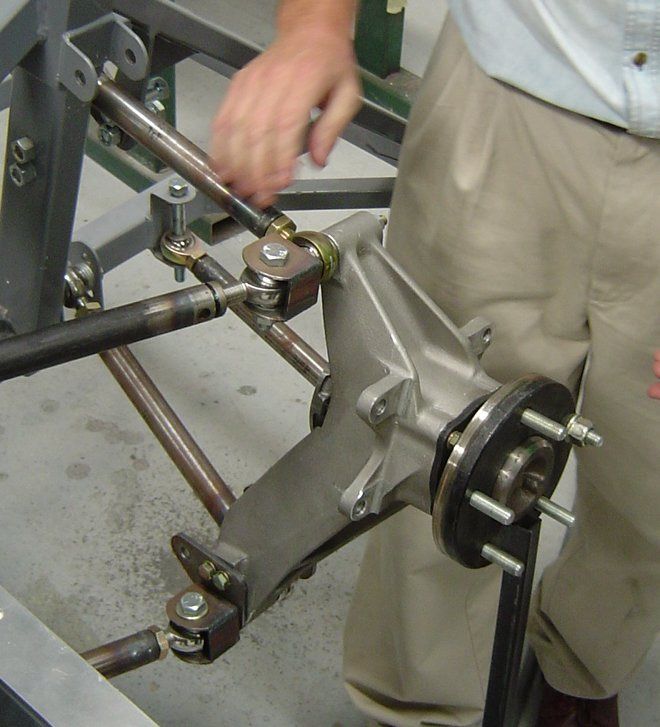
4.10 HEIM JOINTS
Figure LS7 Typical Standard Heim Joint
Heim joints are also known as a rose joints and spherical rod ends.
The Heim joint is a rod end bearing, refer to Figure LS7, that may be used on the end of control
rods, steering links, tie rods, or anywhere a precision articulating joint is required. They
comprise a ball swivel with an opening through which a bolt or other attaching hardware may
pass that is pressed into a circular casing with a threaded shaft attached. The threaded portion
may be either male or female.
Heim joints are made to a variety of standards in terms of strength and durability. Early
versions were prone to failure and had a poor durability history. As a result Heim joints must
only be used in critical applications such as steering and suspension if they meet all of the
following criteria:
• The movement of the rod/component to which the joint is attached does not exceed the
allowable articulation angle of the Heim joint as specified by the Heim joint
manufacturer;
• The Heim joint does not hang-up on existing components; and
• A signatory confirms that the Heim joint has sufficient durability and strength in all
directions for its intended purpose.
It is strongly recommended that Heim joints be protected by suitably designed dust covers to
reduce the risk of premature wear.
Version 2.0 – 1 January 2011 Page 27/LS74Section LS Tyres, Rims, Suspension and Steering
Figure LS7 Heim Joints used in a
suspension application
4.11 LOWERING OR RAISING VEHICLES
None of the codes in VSB 14 allow for the raising of any vehicle where the wheel track has also
been reduced. These vehicles are subject to individual approval on a case-by-case basis.
Raising the height of the vehicle may be performed without certification providing the overall
increase in vehicle height is not more than 50mm. This may be achieved as a single
modification such as the installation of a 50mm lift kit, or by a combination of smaller lifts as
described below:
• the fitting of body blocks or lift kits (50mm maximum if no other modifications resulting
in a change of vehicle height are performed);
• suspension modification, (50mm maximum if no other modifications resulting in a
change of vehicle height are performed);
• changes to tyre size (maximum change in tyre size diameter of 50mm); or
• a combination of the above that results in a change of vehicle height not exceeding
50mm.
Note: In NSW, although vehicles whose height has been changed up to 50mm do
not require certification by an engineering signatory, the registration authority must be
notified of the modification.
Note: In Queensland, special requirements apply if a vehicle if lifted only by the use of
alternate tyres and rims that comply with this section and modification to the
suspension. For further information, please refer to Vehicle Standards Instruction L19
available from the Department of Transport and Main Roads’ website
(www.tmr.qld.gov.au)
Version 2.0 – 1 January 2011 Page 28/LS74Section LS Tyres, Rims, Suspension and Steering When lowering a vehicle, it must continue to comply with the minimum ground clearances and running clearances specified in ADR 43/... and in the AVSR. Where changes in vehicle height occur as a result of modifications, the requirements detailed under Modified Components (refer to Code LS3) that are applicable to individual steering and suspension components continue to apply. Important items such as spline engagement, operating angles of drive shaft joints and in the case of CV joints, the range of axial movement, must remain within design limits for the full range of suspension travel. Also other components such as gear levers, brake hoses etc. may need to be extended depending on the nature of the lift. Steering linkages must continue to operate efficiently and sufficient spline contact surface must be retained for the full range of suspension travel to ensure the safe operation of the vehicle. Otherwise an appropriate steering shaft extension must be used. Following the completion of modifications the vehicle attitude must remain as per original specifications – i.e. the original relationship between the front and rear suspension heights must not be changed and therefore the front and rear suspensions must be both raised by the same amount. The LS7 and LS8 sections of this code have not been adopted for use in Queensland. For details on the requirements for lifting a vehicle by more than 50mm in Queensland, please refer to the LS9 and LS10 sections of the Queensland Code of Practice – Vehicle Modifications, available online from the Department of Transport and Main Roads’ website (www.tmr.qld.gov.au). When lowering a vehicle, the ride height of an unladen vehicle must not be changed by more than one third of the working travel of the suspension from its original height to a rigid bump or rebound position specified by the manufacturer. The suspension bump and rebound positions are measured with any deformable bump or rebound stops removed. The original relationship between the front and rear suspension heights must not be changed and therefore the front and rear suspensions must be both raised or both lowered by the same amount. When raising a vehicle at least two thirds of the original rebound travel must be maintained. The rebound must be limited by the same method as originally employed by the manufacturer. For example limit straps or shock absorber full extension. If coil springs are lowered, or replacement lower coil springs are used, they must have the same end shape as the original springs. They must retain some pre-tension and not come loose when the suspension is in its lowest position (full rebound). They must have clearance between coils at full bump. Lowering blocks used with leaf spring suspensions must be steel, aluminium or metal of equivalent strength and must be positively located to the axle spigot hole and spring centre-bolt. Extended or adjustable shackle plates must not be used to raise vehicles on leaf spring suspensions. Rubber or other resilient bump stops must be provided where the suspension and/or axle are likely to bottom-out on the body or chassis structure. Where the vehicle manufacturer has fitted a load-sensing valve to the braking system as standard equipment, the brake system bias must be checked in both laden and unladen conditions. This check must confirm that the manufacturer’s specifications are maintained. The vehicle’s braking system may require re-certification to the ADR applicable to the category of vehicle at its date of manufacture. Version 2.0 – 1 January 2011 Page 29/LS74
Section LS Tyres, Rims, Suspension and Steering

Version 2.0 – 1 January 2011                                    Page 30/LS74
Section LS Tyres, Rims, Suspension and Steering

5      CERTIFIED MODIFICATIONS (LS CODES)
This section specifies particular requirements and covers limitations on work that may be carried
out under individual LS Codes.

Each Code is supplemented with a checklist as shown in Table LS4 below.

      Table LS4         LS Code Directory

       LS Codes                                                                     Page

          LS1      LHD Vehicle Steering Conversion (Design)                           31

                   Checklist                                                          34

          LS2      LHD Vehicle Steering Conversion                                    39

                   Checklist                                                          40

          LS3      Front Suspension and Steering Modification (Design)                44

                   Checklist                                                          55

          LS4      Front Suspension and Steering Modification                         62

                   Checklist                                                          63

          LS5      Rear Suspension Modification (Design)                              66

                   Checklist                                                          69

          LS6      Rear Suspension Modification                                       71

                   Checklist                                                          72

          LS7      This code has not been adopted for use in Queensland

          LS8      This code has not been adopted for use in Queensland

    Version 2.0 – 1 January 2011                                                 Page 31/LS74
Section LS Tyres, Rims, Suspension and Steering
LHD VEHICLE STEERING CONVERSION (DESIGN)
CODE LS1
SCOPE
Code LS1 provides for the preparation of designs that may be approved by Registration
Authorities for use by other signatories or modifiers. The designs under Code LS1 cover the
design of left hand drive (LHD) to right hand drive (RHD) steering conversions.
Code LS1 does not apply to ADR category L-group vehicles and motor cycles.
DESIGNS COVERED UNDER CODE LS1
The following are designs that may be prepared under Code LS1:
• Design of steering and all associated controls for LHD to RHD steering conversions
using standard components from a manufacturer’s right hand drive variant; and
• Design of steering and all associated controls for LHD to RHD steering conversions
using modified components or components from different vehicle models.
DESIGNS NOT COVERED UNDER CODE LS1
The following are designs that are not covered under Code LS1:
• Design for vehicles originally equipped with ESC that have not been approved by the
vehicle manufacturer or proven through testing;
• Certification of the actual physical modification of particular vehicles (this is covered by
Code LS2);
• Designs for steering conversions on vehicles originally manufactured as right hand
drive (these are covered by Code LS3); and
• Designs for rear suspension modifications (these are covered by Code LS5).
COMPLIANCE WITH APPLICABLE VEHICLE STANDARDS
Modified vehicles must continue to comply with the ADRs to which they were originally
constructed, except as allowed for in the AVSR.
Modified pre-ADR vehicles must continue to comply with the AVSR.
Compliance with the AVSR also means compliance with the equivalent regulations of a State or
Territory of Australia.
Outlined below in Table LS5 are areas of the vehicle that may be affected by the modifications
and that may require re-certification, testing and/or data to show compliance for the modified
vehicle.
Version 2.0 – 1 January 2011 Page 32/LS74Section LS Tyres, Rims, Suspension and Steering
Table LS5 Summary of items that if modified, may detrimentally affect
compliance with applicable ADRs
DETAIL REQUIREMENTS
Steering Column ADR 10x, 10/…
Dashboard ADR 12, 12/…, 21, 21/…
Demisting of Windscreen ADR 15, 15/…
Instrumentation ADR 18x, 18/…
Braking System ADR 7, 7/…, 31, 31/…, 35x, 35/…
To determine the ADRs that apply to the vehicle in question, refer to the applicability tables in
Section LO. Vehicles manufactured on or after 1 January 1969 and prior to 1 July 1988 need to
comply with the Second Edition ADRs whilst vehicles manufactured after this date need to
comply with the Third Edition ADRs. Section LO has separate applicability tables for each
edition.
Alternatively, ADR applicability tables for individual vehicle categories may be referenced on the
Department of Infrastructure and Transport RVCS website at the following address and under
the section titled ADR Applicability Tables:
http://rvcs.dotars.gov.au/
The ADRs apply according to the vehicle’s category and date of manufacture. It is the
responsibility of the signatory to refer to the appropriate ADR applicable to the vehicle.
SPECIFIC REQUIREMENTS
The following are specific requirements to enable design approvals to be issued by Registration
Authorities for left to right hand drive steering conversions under Code LS1.
The design must comply with the requirements of Vehicle Standards Bulletin 4, National Code
of Practice – Steering Conversions for Left Hand Drive Vehicles (VSB 4).
The approval should also comply with the general guidelines contained in both sub-section 2
General Requirements and Specific Requirements in Code LS3 Front Suspension and Steering
Conversion – Design.
Each design should be fully documented, with drawings, calculations, procedural details, test
results and any other data necessary to fully describe the vehicle modifications and should have
a unique design number issued by a Registration Authority.
The design document should contain:
• Details of all drawings needed to fully describe the full extent of the modification;
• Details of any special modification techniques, procedures or adjustments; and
Version 2.0 – 1 January 2011 Page 33/LS74Section LS Tyres, Rims, Suspension and Steering
• Details of any testing of components (e.g. X-rays of modified drag links) and
performance (e.g. bump steer plots) with related acceptance criteria.
Version 2.0 – 1 January 2011 Page 34/LS74Section LS Tyres, Rims, Suspension and Steering
CHECKLIST LS1
LHD VEHICLE STEERING CONVERSION (DESIGN)
CODE LS1
(N/A= Not Applicable, Y=Yes, N=No)
1 STEERING CONVERSION – USING RHD BOX OR RACK
Steering Box/Rack Selection
Is the specified RHD steering box/rack of equivalent capacity to
Y N
the original?
Is the Pitman arm size/length and arc of travel equivalent to the
1.1 Y N
original?
Does the Pitman arm spline match the steering box spline? Y N
Is the drag link attachment taper identical? Y N
Steering Box/Rack Mounting
Does the location and angle of steering box/rack replicate the
original? Y N
1.2
Has the strength of the chassis rail been assessed and
N/A Y N
provisions made to strengthen it as necessary?
Is the proposed steering box/rack mounting design of equivalent
Y N
strength to the original?
Steering Box/Rack coupling
Does the design incorporate the original column coupling (or an
1.3 Y N
equivalent replacement)?
Does the design incorporate the original steering box/rack
Y N
coupling (or an equivalent replacement)?
Idler arm
Does the design ensure that the mounting brackets will be
1.4 N/A Y N
adequately secured to chassis rail?
Does the design idler arm location and angle replicate the
N/A Y N
original?
Drag link
Is the original left hand drive drag link to be used without
N/A Y N
modification? or
Is the original right hand drive drag link to be used without
1.5 N/A Y N
modification? or
Does the designed modified drag link replicate the original? N/A Y N
Are modifications designed in accordance with the specific
N/A Y N
requirements of Code LS1?
[Continued overleaf]
Version 2.0 – 1 January 2011 Page 35/LS74You can also read