Grandstream Networks, Inc - User Manual GSC35XX Series
←
→
Page content transcription
If your browser does not render page correctly, please read the page content below
Grandstream Networks, Inc.
GSC35XX Series
User Manual
COPYRIGHT

©2020 Grandstream Networks, Inc. http://www.grandstream.com
All rights reserved. Information in this document is subject to change without notice. Reproduction or
transmittal of the entire or any part, in any form or by any means, electronic or print, for any purpose without
the express written permission of Grandstream Networks, Inc. is not permitted.
The latest electronic version of this guide is available for download here:
http://www.grandstream.com/support
Grandstream is a registered trademark and Grandstream logo is trademark of Grandstream Networks, Inc.
in the United States, Europe and other countries.

CAUTION
Changes or modifications to this product not expressly approved by Grandstream, or operation of this
product in any way other than as detailed by this guide, could void your manufacturer warranty.

WARNING
Please do not use a different power adaptor with devices as it may cause damage to the products and void
the manufacturer warranty.

                                                                                                      Page |2
                                       GSC35XX Series User Manual
                                            Version 1.0.1.9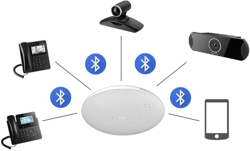
FCC Caution
Any Changes or modifications not expressly approved by the party responsible for compliance could void
the user's authority to operate the equipment. This device complies with part 15 of the FCC Rules.
Operation is subject to the following two conditions: (1) This device may not cause harmful interference,
and (2) this device must accept any interference received, including interference that may cause undesired
operation.

Note: This equipment has been tested and found to comply with the limits for a Class B digital device,
pursuant to part 15 of the FCC Rules. These limits are designed to provide reasonable protection against
harmful interference in a residential installation. This equipment generates uses and can radiate radio
frequency energy and, if not installed and used in accordance with the instructions, may cause harmful
interference to radio communications. However, there is no guarantee that interference will not occur in a
particular installation. If this equipment does cause harmful interference to radio or television reception,
which can be determined by turning the equipment off and on, the user is encouraged to try to correct the
interference by one or more of the following measures:
- Reorient or relocate the receiving antenna.
- Increase the separation between the equipment and receiver.
- Connect the equipment into an outlet on a circuit different from that to which the receiver is connected.
- Consult the dealer or an experienced radio/TV technician for help.

RF Exposure Information (SAR)
This device is designed and manufactured not to be exceeded the emission limits for exposure to radio
frequency RF energy set by the Federal Communications Commission of the United States. The exposure
standard for wireless devices employing a unit of measurement is known as the Specific Absorption Rate
(SAR), and the SAR limit set by FCC is 1.6 W/kg.

This device is complied with SAR for general population/uncontrolled exposure limits in ANSI/IEEE C95.1-
1992, and has been tested in accordance with the measurement methods and procedures specified in OET
Bulletin 65 Supplement C. This device has been tested and meets the FCC RF exposure guidelines when
tested with the device directly contacted to the body. RF exposure compliance with anybody-worn
accessory, which contains metal, was not tested and certified, and use such body-worn accessory should
be avoided.
Changes or modifications not expressly approved by the party responsible for compliance could void the
user’s authority to operate the equipment.

Hereby,Grandstream declares that this device is in compliance with the essential requirements and other
relevant provisions of Directive 1999/5/EC.

                                                                                                   Page |3
                                       GSC35XX Series User Manual
                                            Version 1.0.1.9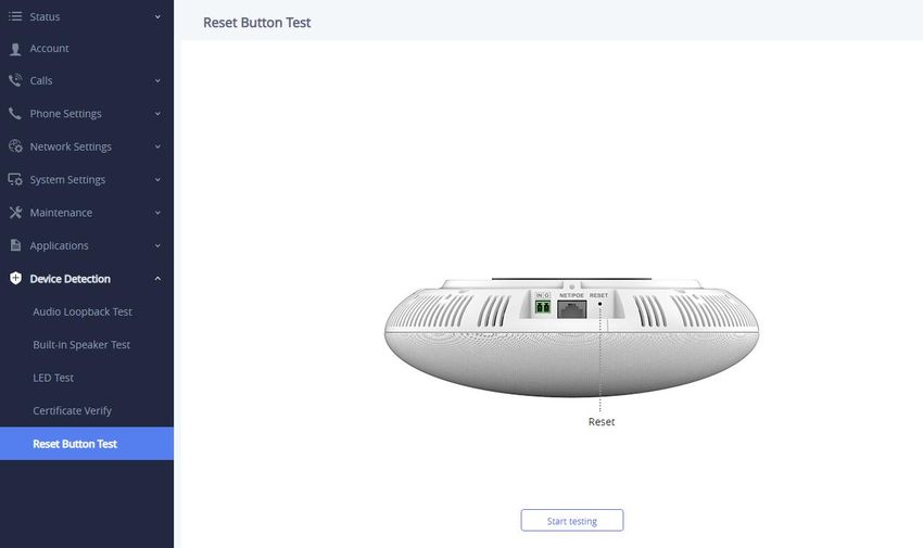
CE Authentication

Hereby, Grandstream Networks, Inc. declares that the radio equipment GSC3510/GSC3505 is in
compliance with Directive 2014/53/EU.
The full text of the EU declaration of conformity is available at the following internet address:
http://www.grandstream.com/support/resources/

                                                                                                    Page |4
                                       GSC35XX Series User Manual
                                            Version 1.0.1.9
GNU GPL INFORMATION

GSC3510/GSC3505 firmware contains third-party software licensed under the GNU General Public License
(GPL). Grandstream uses software under the specific terms of the GPL. Please see the GNU General
Public License (GPL) for the exact terms and conditions of the license.

Grandstream GNU GPL related source code can be downloaded from Grandstream web site from:
http://www.grandstream.com/sites/default/files/Resources/GSC35XX_gpl.zip

                                                                                           Page |5
                                      GSC35XX Series User Manual
                                           Version 1.0.1.9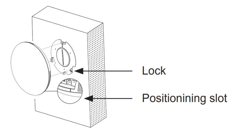
Table of Contents

DOCUMENT PURPOSE ............................................................................................... 11

CHANGE LOG .............................................................................................................. 12

  Firmware Version 1.0.1.9 ........................................................................................................................ 12

  Firmware Version 1.0.1.5 ........................................................................................................................ 12

  Firmware Version 1.0.1.3 ........................................................................................................................ 12

  Firmware Version 1.0.1.1 ........................................................................................................................ 12

  Firmware Version 1.0.0.22 ...................................................................................................................... 12

  Firmware Version 1.0.0.15 ...................................................................................................................... 13

WELCOME ................................................................................................................... 14

PRODUCT OVERVIEW ................................................................................................ 15

  Feature Highlights ................................................................................................................................... 15

  GSC3510/GSC3505 Technical Specifications......................................................................................... 15

GETTING STARTED ..................................................................................................... 17

  Equipment Packaging.............................................................................................................................. 17

  GSC3510/GSC3505 Ports ...................................................................................................................... 18

  GSC3510/GSC3505 LED Indicators ....................................................................................................... 18

  Hardware Installation ............................................................................................................................... 19

     Wall Mount ........................................................................................................................................... 19
     Ceiling Mount ....................................................................................................................................... 20
     Anti-theft Installation ............................................................................................................................ 21

  Powering and Connecting GSC3510/GSC3505 ..................................................................................... 21

     Connecting Wiring Seat ....................................................................................................................... 22

  Access GSC3510/GSC3505 Web GUI ................................................................................................... 22

GSC3510/GSC3505 APPLICATION SCENARIOS ....................................................... 24

  GSC3510/GSC3505 SIP Two-Way/One-Way Intercom System ............................................................. 24

  Multicast Paging Application .................................................................................................................... 27

  Bluetooth Speaker ................................................................................................................................... 30

                                                                                                                                                Page |6
                                                       GSC35XX Series User Manual
                                                            Version 1.0.1.9
2-pin Multi-Purpose Input Applications .................................................................................................... 31

GSC3510/GSC3505 WEB GUI SETTINGS .................................................................. 34

  Status Page Definitions ........................................................................................................................... 34

     Account Status ..................................................................................................................................... 34
     Network Status..................................................................................................................................... 34
     System Info .......................................................................................................................................... 35

  Account Page Definitions ........................................................................................................................ 35

     General Settings .................................................................................................................................. 35
     SIP Settings ......................................................................................................................................... 38
     Codec Settings..................................................................................................................................... 42
     Call Settings ......................................................................................................................................... 44
     Advanced Settings ............................................................................................................................... 47

  Calls Page Definition ............................................................................................................................... 48

     Call ....................................................................................................................................................... 48
     Call History........................................................................................................................................... 49
        Call History → All .............................................................................................................................................50
        Call History → Intercept Record .......................................................................................................................52
        Web GUI Missed Call Notification support.......................................................................................................53
     Contacts ............................................................................................................................................... 54
        Contacts List .....................................................................................................................................................54
        Group ...............................................................................................................................................................58
     Black/White List Settings ..................................................................................................................... 58
        Whitelist...........................................................................................................................................................59
        Blacklist ............................................................................................................................................................60
        Blocking Rules ..................................................................................................................................................61

  Phone Settings Page Definitions ............................................................................................................. 62

     General Settings .................................................................................................................................. 62
     Call Settings ......................................................................................................................................... 62
     Ring Tone ............................................................................................................................................. 64
     Multicast Paging................................................................................................................................... 64

  Network Settings Page Definitions .......................................................................................................... 65

     Ethernet Settings ................................................................................................................................. 65
     Bluetooth .............................................................................................................................................. 67

                                                                                                                                                                Page |7
                                                            GSC35XX Series User Manual
                                                                 Version 1.0.1.9
Wi-Fi Settings....................................................................................................................................... 67
Connect to Wi-Fi Network ................................................................................................................................67
Wi-Fi Settings description ................................................................................................................................69
OpenVPN® Settings ............................................................................................................................ 70
Advanced Network Settings................................................................................................................. 71
System Settings Page Definitions ........................................................................................................... 72
Time Settings ....................................................................................................................................... 72
Security Settings .................................................................................................................................. 72
Preferences.......................................................................................................................................... 74
TR-069 ................................................................................................................................................. 74
Sensor Settings.................................................................................................................................... 75
Backup ................................................................................................................................................. 76
Maintenance Page Definitions ................................................................................................................. 77
Upgrade ............................................................................................................................................... 77
System Diagnosis ................................................................................................................................ 81
Event Notification ................................................................................................................................. 83
Application Page Definitions .................................................................................................................... 84
LDAP Book........................................................................................................................................... 84
Recording............................................................................................................................................. 85
Music .................................................................................................................................................... 86
Device Detection Page Definitions .......................................................................................................... 86
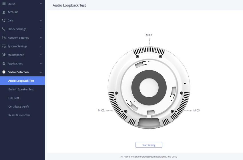
Audio Loop Test ................................................................................................................................... 86
Built-in Speaker Test ............................................................................................................................ 87
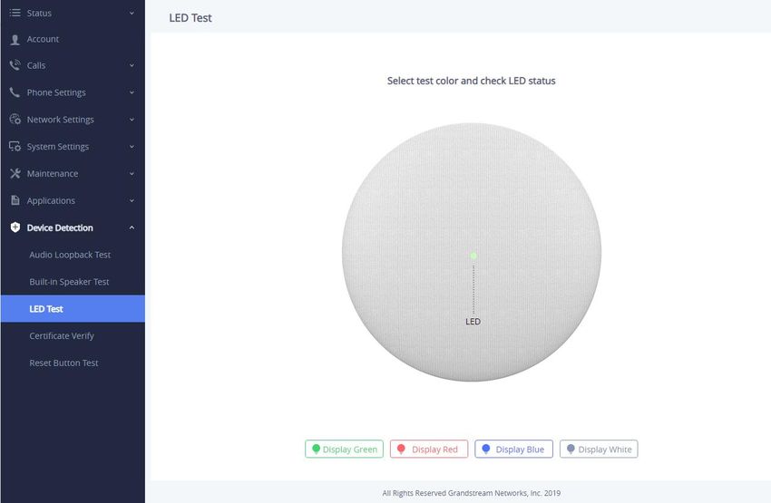
LED Test .............................................................................................................................................. 88
Certificate Verify ................................................................................................................................... 88
Reset Button Test ................................................................................................................................ 88
EXPERIENCING THE GSC3510/GSC3505 .................................................................. 90
Page |8
GSC35XX Series User Manual
Version 1.0.1.9
Table of Tables

Table 1: GSC3510/GSC3505 Features in a Glance ................................................................................... 15
Table 2: GSC3510/GSC3505 Technical Specifications .............................................................................. 15
Table 3: Equipment Packaging ................................................................................................................... 17
Table 4: GSC3510/GSC3505 Ports Description ......................................................................................... 18
Table 5: GSC3510 LED Indicators .............................................................................................................. 18

                                                        Table of Figures

Figure 1: GSC3510/GSC3505 Package Content ....................................................................................... 17
Figure 2: GSC3510/GSC3505 Ports ........................................................................................................... 18
Figure 3: Wall Mount - Step 1 ..................................................................................................................... 19
Figure 4: Wall Mount - Step 2 ..................................................................................................................... 19
Figure 5: Wall Mount - Step 3 ..................................................................................................................... 19
Figure 6: Wall Mount - Step 4 ..................................................................................................................... 19
Figure 7: Ceiling Mount - Step 1 & 2 ........................................................................................................... 20
Figure 8: Ceiling Mount - Step 3 ................................................................................................................. 20
Figure 9: Ceiling Mount - Step 4 ................................................................................................................. 20
Figure 10: Ceiling Mount - Step 5 ............................................................................................................... 20
Figure 11: Anti-theft Installation ................................................................................................................... 21
Figure 12: Powering GSC3505/GSC3510 .................................................................................................. 21
Figure 13: Connecting Wiring Seat ............................................................................................................. 22
Figure 14: GSC3510 Web GUI – Login ...................................................................................................... 23
Figure 15: SIP 2-Way/1-Way Paging Diagram ............................................................................................ 24
Figure 16: SIP Account Configuration ......................................................................................................... 25
Figure 17: SIP Account Status .................................................................................................................... 25
Figure 18: Default Blocking Rules ............................................................................................................... 26
Figure 19: Whitelisted Devices.................................................................................................................... 26
Figure 20: Multicast paging Diagram .......................................................................................................... 27
Figure 21: Multicast Paging Listening Addresses ....................................................................................... 28
Figure 22: Multicast Paging – Paging Priority Active .................................................................................. 28
Figure 23: Multicast Paging - Priority Barge ............................................................................................... 29
Figure 24: Connecting the GSC3510/GSC3505 as a Bluetooth Speaker .................................................. 30
Figure 25: 2-pin Multi-Purpose Input Applications ...................................................................................... 31
Figure 26: Sensor Settings.......................................................................................................................... 31
Figure 27: Sensor Setting – Trigger time .................................................................................................... 32
Figure 28: Sensor Setting - Linkage Function - Play Audio ........................................................................ 33
Figure 29: Sensor Setting - Linkage Function - Make Call ......................................................................... 33

                                                                                                                                           Page |9
                                                      GSC35XX Series User Manual
                                                           Version 1.0.1.9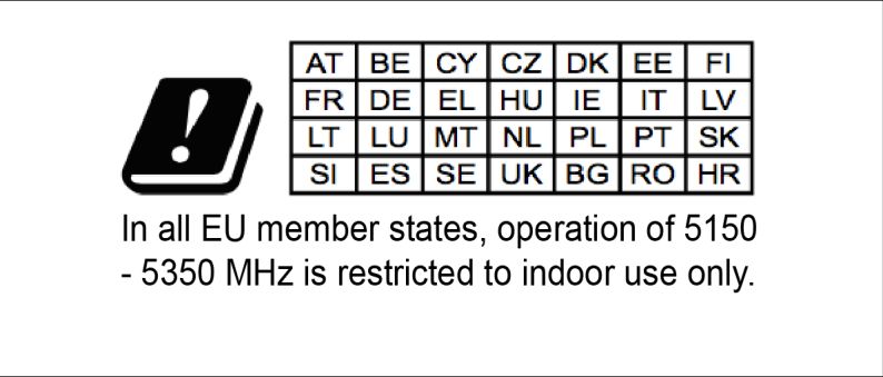
Figure 30: Click-to-Dial Feature .................................................................................................................. 49
Figure 31: Outgoing call in progress and accepted .................................................................................... 49
Figure 32: Call History → All........................................................................................................................ 50
Figure 33: Call details under Call History → All........................................................................................... 51
Figure 34: Add number from call history to an existing contact .................................................................. 51
Figure 35: Call History → Intercept Record ................................................................................................. 52
Figure 36: Call details under Call History → Intercept Record .................................................................... 53
Figure 37: Web GUI Missed Call Notification .............................................................................................. 53
Figure 38: Contacts → Contacts List ........................................................................................................... 54
Figure 39: Add New Contact ....................................................................................................................... 54
Figure 40: Contacts → Group...................................................................................................................... 58
Figure 41: Add New Group.......................................................................................................................... 58
Figure 42: Whitelist section ......................................................................................................................... 59
Figure 43: Add phonebook contacts to whitelist.......................................................................................... 59
Figure 44: Add blocked numbers to whitelist .............................................................................................. 60
Figure 45: Add Manually to Whitelist........................................................................................................... 60
Figure 46: Blacklist Section ......................................................................................................................... 60
Figure 47: Add from Call History to Blacklist ............................................................................................... 61
Figure 48: Wi-Fi Basics Page...................................................................................................................... 68
Figure 49: Connect to Wi-Fi Network .......................................................................................................... 68
Figure 50: GSC3510/GSC3505 Connect to Wi-Fi-Show Advanced Options.............................................. 69
Figure 51: GSC3510/GSC3505 Backup Page ............................................................................................ 76
Figure 52: Backup content selection ........................................................................................................... 76
Figure 53: Generated Backup ..................................................................................................................... 77
Figure 54: Device Detection - Audio Loop Test ........................................................................................... 87
Figure 55: Device Detection - Built-in Speaker Test ................................................................................... 87
Figure 56: Device Detection - LED Test ...................................................................................................... 88
Figure 57: Device Detection - Reset Button Test ........................................................................................ 89

                                                                                                                                          P a g e | 10
                                                      GSC35XX Series User Manual
                                                           Version 1.0.1.9
DOCUMENT PURPOSE
This document describes how to configure the GSC3510 via web UI menu to fully manipulate device's
features. Please visit http://www.grandstream.com/support to download the latest “GSC3510 User Manual”.
This guide covers following topics:
▪ Product Overview
▪ Getting Started
▪ Hardware Installation
o Wall Mount
o Ceiling Mount
o Anti-theft Installation
▪ GSC3510/GSC3505 Application Scenarios
o GSC3510/GSC3505 SIP two-way/one-way Intercom System
o Multicast Paging Application
o Bluetooth Speaker
o 2-pin Multi-Purpose Input Applications
▪ GSC3510 Web GUI Settings
▪ Experiencing the GSC3510
P a g e | 11
GSC35XX Series User Manual
Version 1.0.1.9CHANGE LOG
This section documents significant changes from previous versions of user manual for GSC35XX Series.
Only major new features or major document updates are listed here. Minor updates for corrections or editing
are not documented here.
Firmware Version 1.0.1.9
• Added ability to generate a zip file for multiple recording files. [Record]
• Added the missed calls notification on Web UI. [Missed Call Notification]
• Optimized web UI tooltips.
• Optimized the sensor functions of the device.
Firmware Version 1.0.1.5
• Added the incoming rules options for each account [Incoming Call Rules]
Firmware Version 1.0.1.3
• Added to support failover mechanism based on DNS SRV. [Register Before DNS SRV Fail-over]
• Added the ability to delay the auto-answer. [Automatic Answer Ringing Time (s]
• Added the ability to adjust the Busy Tone Expiration. [Busy Tone Ring Time (s)]
• Added support for visibility timeout to nearby devices. [Bluetooth]
• Added the option to Enable/Disable web access. [Security Settings]
• Added Ability to disable IP2location and Wifi Certification. [Allow AutoConfig service access]
• Added the ability to play/stream the music based on set schedule. [Music]
• Added the ability to support MP3 Format files on the Music Feature. [Music]
• Added the ability to display date/time on the Web UI. [System Info]
Firmware Version 1.0.1.1
• Added the ability to stream Radio/Music on the device. [MUSIC/RADIO STREAMING]
• Added pairing PIN code with Bluetooth device. [BLUETOOTH PIN CODE]
• Added minimum & maximum TLS version. [MIN/MAX TLS VERSION]
• Added a prompt to restart the device after modifying PNP (3CX) Auto Provision
• Added an ability to adjust the volume during playing the radio/music
• Changed “DATE” for the time display under call history and recording files to “TIME AND DATE”
• Optimized web UI prompts
• Optimized the audio quality
Firmware Version 1.0.0.22
• Added support for Date/Time settings. [Time Settings]
P a g e | 12
GSC35XX Series User Manual
Version 1.0.1.9• Added volume control settings. [Preferences]
• Added support for Sensor Profile Schedule/ Profile Action. [2-pin Multi-Purpose Input Applications]
[Sensor Settings]
• Added support for numbers with + on the whitelist/blacklist. [Black/White List Settings]
• Removed Red LED on missed call/voicemail when GSC3510 connected via Bluetooth.
[GSC3510/GSC3505 LED Indicators]
• Removed Subscribe for MWI settings. [SIP Settings]
• Removed Voicemail Access Number settings. [General Settings]
• Removed SIP Display Name settings. [General Settings]
Firmware Version 1.0.0.15
• This is the initial version.
P a g e | 13
GSC35XX Series User Manual
Version 1.0.1.9WELCOME
Thank you for purchasing Grandstream GSC3510/GSC3505 SIP Intercom speakers. The GSC3505 is a
one-way SIP Intercom Speaker and GSC3510 is a two-way full-duplex SIP intercom speaker/microphone,
both featuring one 100Mbps Ethernet port with PoE/PoE+, integrated dual-band 2.4G/5G Wi-Fi, integrated
Bluetooth, high fidelity 8W speaker and a multi-purpose input port supporting a wide range of peripherals,
3 directional microphones with Multichannel Microphone Array Design (MMAD) available for GSC3510 only.
Both GSC3505 and GSC3510 with their Hi-Fi speaker delivers full-band audio, while GSC3510 adds a
state-of-art microphone array with pickup distance up to 4.2 meters. The built-in whitelist and blacklist
features enable easy filtering of unwanted calls from the Internet. Its modern industrial design and rich
features make it ideal for classrooms, hospitals, apartments, dormitories and much more.
P a g e | 14
GSC35XX Series User Manual
Version 1.0.1.9PRODUCT OVERVIEW
Feature Highlights
The following table contains the major features of the GSC3510/GSC3505:
Table 1: GSC3510/GSC3505 Features in a Glance
• Up to 16 SIP accounts.
GSC3510
GSC3505 • Ethernet RJ45 10/100Mbps, PoE/PoE+, Integrated Bluetooth, Wi-Fi.
• Both GSC3505 and GSC3510 HD with their Hi-Fi speaker delivers full-band
audio, Hands-free speakerphone with HD acoustic chamber, advanced
acoustic echo cancellation, while GSC3510 adds a state-of-art microphone
array with pickup distance up to 4.2 meters.
GSC3510/GSC3505 Technical Specifications
The following table resumes all the technical specifications including the protocols / standards supported,
voice codecs, telephony features, languages and upgrade/provisioning settings for GSC3510/GSC3505.
Table 2: GSC3510/GSC3505 Technical Specifications
Protocols/Standards SIP RFC3261, TCP/IP/UDP, RTP/RTCP, HTTP/HTTPS, ARP, ICMP, DNS (A
record, SRV, NAPTR), DHCP, PPPoE, SSH, TFTP, NTP, STUN, SIMPLE, LLDP-
MED, LDAP, TR-069, 802.1x, TLS, SRTP, IPv6, OpenVPN®.
Network Interfaces Ethernet RJ45 10/100Mbps ports with integrated PoE/PoE+.
Bluetooth Yes, integrated. Bluetooth.
Wi-Fi Yes, dual-band 2.4 & 5GHz with 802.11 a/b/g/n.
Alarm Input 1 Alarm Input Port.
Voice Codec G.711µ/a, G.722 (wide-band), G.722.1, G.722.1C, G.726-32, iLBC, Opus,
G.729A/B in-band and out-of-band DTMF (In audio, RFC2833, SIP INFO).
P a g e | 15
GSC35XX Series User Manual
Version 1.0.1.9Telephony Features Hold, transfer, forward (unconditional/no-answer/busy), call park/pickup,
downloadable contacts, call record, call log, auto answer, click-to-dial, flexible dial
plan.
HD Audio Yes, HD speakerphone with support for wideband audio.
QoS Layer 2 QoS (802.1Q, 802.1p) and Layer 3 (ToS, DiffServ, MPLS) QoS.
Security User and administrator level passwords, MD5 and MD5-sess based authentication,
256-bit AES encrypted configuration file, TLS, SRTP, HTTPS, 802.1x media access
control.
Multi-languages English, Chinese and Portuguese.
Upgrade/ Firmware upgrade via TFTP / HTTP / HTTPS or local HTTP upload, mass
Provisioning provisioning using TR-069 or AES encrypted XML configuration file.
Power and Green
Integrated PoE* 802.3af Class 3, PoE+ 802.3at, Class 4.
Energy Efficiency
Package Content GSC3510/GSC3505, Metal Bracket, Plastic Bracket, Wiring Seat, Hang rope
plate, 3x Screw (PM 3 x 50), 3x Screw (PA 3.5 x 20), 1 x Screw (M3 x 15),
Hexagonal Screwdriver, 3 x Plastic Expansion Bolt, 3 x M3 NUT, Quick Installation
Guide, GPL license.
Physical Unit Dimensions: 215.32mm (diameter) x 68.7mm (depth)Unit Weight: 0.8kg, Box
Weight: 1.39k
Compliance FCC: Part 15 (CFR 47) Class B; UL 60950 (power adapter); FCC Part 15C, FCC
Part 15E, MPE
CE: EN 55032; EN 55024; EN 61000-3-2; EN 61000-3-3; EN 60950-1; EN 301
489-1/17; EN 300 328; EN 301 893; EN 62311; RoHS
RCM: AS/NZS CISPR 32/24; AS/NZS 60950.1; AS/NZS 4268
IC: ICES 003, RSS 247, RSP-100, RSS 102
P a g e | 16
GSC35XX Series User Manual
Version 1.0.1.9GETTING STARTED
This chapter provides basic installation instructions including the list of the packaging contents and also
information for obtaining the best performance with the GSC3510/GSC3505.
Equipment Packaging
Table 3: Equipment Packaging
GSC3510/GSC3505
• 1x GSC3510/GSC3505 Main Case.
• 1x Metal Bracket.
• 1x Plastic Bracket.
• Wiring Seat.
• Hang rope plate.
• 3x Screw (PM 3x50)
• 3x Screw (PA 3.5 x20).
• 1x Screw (M3x15)
• Hexagonal Screwdriver.
• 3x Plastic Expansion Bolt.
• 3x M3 NUT.
• 1x Quick Installation Guide.
• 1x GPL license.
Figure 1: GSC3510/GSC3505 Package Content
Note: Check the package before installation. If you find anything missing, contact your system
administrator.
P a g e | 17
GSC35XX Series User Manual
Version 1.0.1.9GSC3510/GSC3505 Ports
1 2 3
Figure 2: GSC3510/GSC3505 Ports
Table 4: GSC3510/GSC3505 Ports Description
NO. Name Description
Factory reset button. Press for 10 seconds to reset factory default
1 RESET
settings.
2 NET/PoE Ethernet RJ45 port (10/100Mbps) supporting PoE/PoE+.
3 2-PIN Port 2-PIN Multi-Purpose Input Port.
GSC3510/GSC3505 LED Indicators
The GSC3510/GSC3505 contains 4 types of colored LEDs (Red, Green, White and Blue light) that are used
in some specific situations and operations. Please, refer to the following table describing each one of the
LED Indicators status:
Table 5: GSC3510 LED Indicators
Color LED Indicator Status Description
Fast Flashing (every 1s) Rebooting/factory resetting
Unhandled event: (Included Missed call(s), new voice
mails, new SIP messages).
Red Light Slow Flashing (On 1s, Off 2s) Note: In case the GSC3510/3505 is connected via
Bluetooth, Missed Call/Voicemail Red LED will not
light and will remain flashing in blue.
Solid Red The contacts/storage space is full
Fast Flashing (every 1s) Incoming/outgoing call
Green Light Slow Flashing (On 1s, Off 2s) Call on hold.
Solid Green During the call.
P a g e | 18
GSC35XX Series User Manual
Version 1.0.1.9White Light Fast Flashing (every 1s) Upgrading the firmware.
Blue Light Fast Flashing (every 1s) Bluetooth pairing.
Hardware Installation
GSC3510/GSC3505 can be mounted on the wall or ceiling. Please refer to the following steps for the
appropriate installation
Wall Mount
1. Locate the equipment holder on the desired position with arrow up. Drill three holes on the wall
referring to the positions of holes on the metal bracket.
2. Fix the metal bracket on the wall by expansion screws.
3. Align the position line on device’s back cover with the positioning slot.
4. Rotate the device clockwise until it is locked on the right position.
Figure 3: Wall Mount - Step 1
Figure 4: Wall Mount - Step 2
Figure 5: Wall Mount - Step 3
Figure 6: Wall Mount - Step 4
P a g e | 19
GSC35XX Series User Manual
Version 1.0.1.9Ceiling Mount
1. Put the ceiling mounting (metal bracket) in the ceiling’s center and mark the position of the three
screws holes.
2. Drill a round hole with a diameter of 18mm for Ethernet cable. The distance between its center and
the highlighted hole on the plastic bracket should be 35mm.
3. Fix the plastic and metal brackets on the ceiling with flat-head screws and locknuts. Then place
and Ethernet cable pass through the 18mm-round hole.
4. Align the position line on device’s back cover with the positioning slot.–––
5. Rotate the device clockwise until it is locked on the right position.
Figure 7: Ceiling Mount - Step 1 & 2 Figure 8: Ceiling Mount - Step 3
Figure 9: Ceiling Mount - Step 4 Figure 10: Ceiling Mount - Step 5
P a g e | 20
GSC35XX Series User Manual
Version 1.0.1.9Anti-theft Installation
After the device is assembled with the metal bracket support on the wall or ceiling, use the anti-detachable
screw (M3x15) in order to prevent theft.
Figure 11: Anti-theft Installation
Powering and Connecting GSC3510/GSC3505
The GSC3510/GSC3505 can be powered on using PoE/PoE+ switch or PoE injector using following steps:
• Step 1: Plug a RJ45 Ethernet cable into the network port of the GSC3510/GSC3505.
• Step 2: Plug the other end into the power over Ethernet (PoE) switch or PoE injector.
Figure 12: Powering GSC3505/GSC3510
P a g e | 21
GSC35XX Series User Manual
Version 1.0.1.9Connecting Wiring Seat
GSC3505/GSC3510 support to connect a “Key & LED” or “Normal Key” to the 2-pin port via Wiring Seat
using following steps:
• Step 1: Take the wiring seat from the install kits.
• Step 2: Connect the “Key & LED” or “Normal Key” with the wiring seat (as shown in the figure
below)
Note: This port supports the parallel connection of an incandescent lamp (with less than 1W) or an LED
lamp (with less than 100mA).
Figure 13: Connecting Wiring Seat
Access GSC3510/GSC3505 Web GUI
The GSC3510/GSC3505 embedded Web server responds to HTTP/HTTPS GET/POST requests.
Embedded HTML pages allow users to configure the application phone through a Web browser such as
Microsoft’s IE, Mozilla Firefox, Google Chrome and etc.
P a g e | 22
GSC35XX Series User Manual
Version 1.0.1.9Figure 14: GSC3510 Web GUI – Login
Users can use a computer connected to the same network as the GSC3510/GSC3505 to discover and
access the GSC3510/GSC3505 Configuration Interface using its MAC Address.
Please, refer to the following steps in order to access the GSC3510/GSC3505 Web GUI:
1. Locate the MAC address on the MAC tag of the unit, which is on the underside of the device, or on
the package.
2. From a computer connected to same network as the GSC3510/GSC3505, type in the following
address using the GSC3510/GSC3505’s MAC address on your browser: https://gsc_.local
Example: if a GSC3510/GSC3505 has the MAC address C0:74:AD:xx:xx:xx, this unit can be accessed by
typing https://gsc_c074adxxxxxx.local on the browser.
P a g e | 23
GSC35XX Series User Manual
Version 1.0.1.9GSC3510/GSC3505 APPLICATION SCENARIOS
GSC3510/GSC3505 SIP Two-Way/One-Way Intercom System
GSC3510/GSC3505 can be used as an Intercom System using built-in SIP accounts, once the SIP account
registered the device can receive paging/intercom calls and it will automatically answer calls coming from
whitelisted numbers.
Note: GSC3505 is SIP one-way Intercom, while GSC3510 is two-way Intercom.
Figure 15: SIP 2-Way/1-Way Paging Diagram
To register a SIP account on the GSC3510/GSC3505 the user needs to go under Account → Account X
→ General Settings, and enter the account information as below, then save and apply the configuration.
P a g e | 24
GSC35XX Series User Manual
Version 1.0.1.9Figure 16: SIP Account Configuration
Once the account registered correctly, the GSC3510/GSC3505 will show the account status as
“Registered” under Status → Account Status.
Figure 17: SIP Account Status
By default, the GSC3510/GSC3505 Blocks non-whitelisted number under Calls → Black/White List
Settings → Blocking Rules, user needs to either allow Non-White list calls or to set up a Whitelist that
contains the number that will be allowed to call the GSC3510/GSC3505.
P a g e | 25
GSC35XX Series User Manual
Version 1.0.1.9Figure 18: Default Blocking Rules
On the screenshot below, only number 1001 is allowed to call GSC3510/GSC3505:
Figure 19: Whitelisted Devices
As soon as a SIP call is received by the GSC3510/GSC3505, it first checks if the Caller ID number is
allowed on the Whitelist and then answers automatically.
Notes:
• GSC3510/GSC3505 is an intercom system and auto-answers all whitelisted numbers.
• By default, GSC3510/GSC3505 plays a Warning tone when auto answering incoming calls, this
warning tone can be disabled under Account → Account X → Call Settings, “Play Warning Tone
for Auto Answer Intercom”.
P a g e | 26
GSC35XX Series User Manual
Version 1.0.1.9Multicast Paging Application
Multicast paging is an approach to let different SIP users to listen for paging calls from a common multicast
IP address. In multicast page call, an audio connection will be set up from sender to receiver, but the
receiver will be only able to receive audio, a one-way communication. The 2 entities, Sender/Receiver, must
be located on same LAN (same broadcast domain).
Figure 20: Multicast paging Diagram
To receive multicast page, GSC3510/GSC3505 must be well configured to listen to the right address and
port. The configuration is located under Phone Settings → Multicast Paging. Up to 10 listening addresses
are supported with priority levels from 1 to 10.
Note: Multicast paging configuration requires a reboot to take effect.
P a g e | 27
GSC35XX Series User Manual
Version 1.0.1.9Figure 21: Multicast Paging Listening Addresses
In above screenshot, Listening Address “237.11.10.11:6767” with label “Sales” has the highest priority.
Users can enable “Paging Priority Active” option (under Multicast Paging tab) to accept incoming paging
calls during active multicast paging. The paging call with higher priority than active one will be accepted.
Figure 22: Multicast Paging – Paging Priority Active
P a g e | 28
GSC35XX Series User Manual
Version 1.0.1.9In the case of receiving a multicast paging call while on a unicast SIP call, the GSC3510/GSC3505 can
choose to either keep the SIP call or to hold this last and allow the multicast call depending on paging call
priority.
This is can be set using “Paging Barge” option. If the option is set to “Disabled” all incoming multicast paging
calls will be dropped while on a SIP call. If the multicast paging call has higher priority than the value set on
“Paging Barge”, the SIP call will be put on hold and GSC3510/GSC3505 will the incoming multicast paging.
Figure 23: Multicast Paging - Priority Barge
P a g e | 29
GSC35XX Series User Manual
Version 1.0.1.9Bluetooth Speaker
The GSC3510/GSC3505 can be used as a Bluetooth speaker for another device and it needs to be
connected via Bluetooth to that device. Users need to turn on GSC3510/GSC3505’s Bluetooth function first.
The first time when using a new Bluetooth device with the GSC3510/GSC3505, "pair" the device with
GSC3510/GSC3505 so that both devices know how to connect securely to each other.
Figure 24: Connecting the GSC3510/GSC3505 as a Bluetooth Speaker
Please, refer to the following steps in order to pair and connect the GSC3510/GSC3505 to the device:
1. Go to GSC3510/GSC3505 Web GUI → Network Settings →Bluetooth Settings.
2. Enable “Bluetooth Settings” function, and enable the option “Visible to Nearby Bluetooth Device” in
order to make the GSC3510/GSC3505 visible for other devices for 2 minutes (When the 2 minutes
are achieved, and you still didn’t connect it, please enable again the option to keep it visible)
3. Go to your Device’s Bluetooth settings I order to search for visible devices. The
GSC3510/GSC3505 is going to be listed within the visible devices with the “Device Name”
configured on the Web GUI.
4. Click on the GSC3510/GSC3505 device’s name in order to pair and connect it to the device
Note: The GSC3510/GSC3505 will only play the role of a speaker when it is connected to another device
via Bluetooth. Users cannot use the GSC3510/GSC3505 to take control of calls made/received by the
device connected to it.
P a g e | 30
GSC35XX Series User Manual
Version 1.0.1.92-pin Multi-Purpose Input Applications
GSC3510/GSC3505 supports 2-pin multi-purpose input that can connect a “Key with LED” or “Normal Key”.
By configuring the sensor settings users can enable the GSC3510/GSC3505 to play an audio file
(.wav/.mp3 format), trigger a SIP call to a pre-configured extension, or to start recording audio locally when
triggered.
Voice prompt
Play sound when trigger switch,
support upload custom ring/alarm sound
Call dial
Dial the configured number when switch is triggered
Call recording
Record with one key when the switch is triggered
Turn off the lights
The key will trigger the light ON and OFF.
Support parallel connection of an incandescent lamp (with
less than 1W) or an LED lamp (with less than 100mA).
Figure 25: 2-pin Multi-Purpose Input Applications
To configure sensor settings, access to web UI → System Settings → Sensor Setting.
Figure 26: Sensor Settings
P a g e | 31
GSC35XX Series User Manual
Version 1.0.1.9Under Basic Setting section, users can set “Sensor Type” and “Trigger Type”.
Two states are supported by the Input circuit for the “Sensor Type”:
1. Normally Open where the contact is disconnected when there is no electricity
2. Normally Close where the contact is connected when there is no electricity.
Users could set “Trigger Type” to:
1. Edge Triggered: When selected, the notification is triggered only when the level changes (high
level to low level, or low level to high level.
2. Level Triggered: When selected, only high level (1) will trigger the notification.
Under “Trigger time” section, users can click on “Add” in order to configure different schedules and a trigger
profile for each one as shown in the figure below:
Figure 27: Sensor Setting – Trigger time
• Cycle Time: The alarm can be configured to be triggered all days of the week, in this case “All
days” option needs to be checked. Or to some specific days of the week with Start and End time,
in this case “Period of Time” option needs to be checked for users to be able to configure Time
and Frequency options.
• Play Audio: If checked, GSC3510/GSC3505 will play a sound when the switch is triggered during
the schedule. Users can select a “Prompt Tone” from available tones or upload a customized tone.
P a g e | 32
GSC35XX Series User Manual
Version 1.0.1.9Figure 28: Sensor Setting - Linkage Function - Play Audio
• Make Call: If checked, GSC3510/GSC3505 will dial out configured numbers on “Dial out extension”
fields (up to 2 numbers supported) when the switch is triggered during the schedule.
Figure 29: Sensor Setting - Linkage Function - Make Call
• Recording: If selected, GSC3510/GSC3505 will record audio using built-in microphones.
Recorded files can be found under Applications → Recording
Note: Up to 7 different Alarm Schedule/Linkage function can be configured in the GSC3510/GSC3505.the
list of schedules and linkage functions will be shown in the lower section of the page (as shown in figure
Figure 27: Sensor Setting – Trigger time), users can edit or delete the Alarm schedule by clicking on
Edit or Delete buttons respectively.
P a g e | 33
GSC35XX Series User Manual
Version 1.0.1.9GSC3510/GSC3505 WEB GUI SETTINGS
The GSC3510/GSC3505 embedded Web server responds to HTTP/HTTPS GET/POST requests.
Embedded HTML pages allow users to configure the application phone through a Web browser such as
Microsoft’s IE, Mozilla ,Firefox, Google Chrome and etc.
Status Page Definitions
Account Status
Account 16 SIP accounts on the device.
Number SIP User ID for the account.
SIP Server URL or IP address, and port of the SIP server.
Status Registration status for the SIP account.
Network Status
MAC Address Global unique ID of device, in HEX format. The MAC address will be used
for provisioning and can be found on the label coming with original box and
on the label located on the back of the device.
NAT Type Type of NAT connection used by the device.
Address Type Configured address type:
DHCP, Static IP or PPPoE.
IPv4 Address IP address of the device.
Subnet Mask Subnet mask of the device.
Default Gateway Default gateway of the device.
DNS Server 1 DNS Server 1 of the device.
DNS Server 2 DNS Server 2 of the device.
IPv6 Address Type Configured address type:
DHCP, Static IP or PPPoE.
IPv6 Address IPv6 address of the device.
IPv6 DNS Server 1 IPv6 DNS Server 1 of the device.
IPv6 DNS Server 2 IPv6 DNS Server 2 of the device.
P a g e | 34
GSC35XX Series User Manual
Version 1.0.1.9System Info
Product Model Product model of the device: GSC3510/GSC3505.
Hardware Revision Hardware version number.
Part Number Product part number.
Serial Number Product’s serial number.
System Version Firmware version ID. This is the main software release version, which is
used to identify the software system of the device.
Recovery Version Recovery image version.
Boot Version Booting code version.
Kernel Version The kernel version.
System Time Indicates Date and Time.
System Up Time System up time since the last reboot.
Account Page Definitions
GSC3510/GSC3505 has 16 independent SIP accounts. Each SIP account has an individual configuration
page.
General Settings
Account Registration
Account Active Indicates whether the account is active. 1st account active by default.
Account Name Configures the name associated with each account.
SIP Server Specifies the URL or IP address, and port of the SIP server. This should
be provided by VoIP service provider (ITSP).
SIP User ID Configures user account information provided by your VoIP service
provider (ITSP). It's usually in the form of digits similar to phone number or
actually a phone number.
SIP Authentication ID Configures the SIP service subscriber's Authenticate ID used for
authentication. It can be identical to or different from the SIP User ID.
SIP Authentication Configures the account password required for the device to authenticate
Password with the ITSP (SIP) server before the account can be registered. After
saving, it will appear as hidden for security purpose.
Display Name Configures the subscriber's name (optional) that will be used for Caller ID
display.
P a g e | 35
GSC35XX Series User Manual
Version 1.0.1.9Tel URI Indicates E.164 number in “From” header by adding “User=Phone”
parameter or using “Tel:” in SIP packets, if the device has an assigned
PSTN Number.
• Disabled: Will use “SIP User ID” information in the Request-Line and
“From” header.
• User=Phone: “User=Phone” parameter will be attached to the
Request-Line and “From” header in the SIP request to indicate the
E.164 number. If set to "Enable".
• Enabled: "Tel:" will be used instead of "sip:" in the SIP request.
Please consult your carrier before changing this parameter. Default is
“Disabled”.
Network Settings
Outbound Proxy Configures the IP address or the domain name of the primary outbound
proxy, media gateway or session border controller. It's used by the device
for firewall or NAT penetration in different network environments. If a
symmetric NAT is detected, STUN will not work and only an outbound
proxy can provide a solution
Secondary Outbound Sets IP address or domain name of the secondary outbound proxy, media
Proxy gateway or session border controller. The device will try to connect the
Secondary outbound proxy only if the primary outbound proxy fails.
DNS Mode Defines which DNS service will be used to lookup IP address for SIP
server’s hostname. There are three modes:
• A Record
• SRV
• NATPTR/SRV
To locate the server by DNS SRV set this option to "SRV" or
"NATPTR/SRV". Default setting is "A Record".
DNS SRV Fail-over Mode The option will decide which IP is going to be used in sending subsequent
SIP packets (ex: Register refresh requests) after the list of IPs for SIP
server host is resolved with DNS SRV.
• Default (prefer server with lowest SRV priority):
The device will always prefer to send SIP requests to the available server
having the lowest priority, and in case it’s down it contacts the next one,
but once the server having lowest priority is UP again, the device will switch
over to this one.
P a g e | 36
GSC35XX Series User Manual
Version 1.0.1.9You can also read