Electric Service Guidelines - May 2020 TSN 449260 - Oncor
←
→
Page content transcription
If your browser does not render page correctly, please read the page content below
Electric
Service
Guidelines

TSN 449260

May 2020
Important Notice Regarding Removal of
     Oncor Electric Delivery Company LLC Meters to Perform Work on Customer's Premise

Effective October 15, 2013, as provided for in the Oncor Tariff for Retail Delivery Service approved by the
Public Utility Commission of Texas (PUC), unauthorized removal of an Oncor meter, which includes any work
on the customer's equipment that would require cutting the seal and removal of the meter, will result in a
charge to the customer of $19.20. Additional charges may also be applied if tampering is determined to have
occurred.

To ensure that a customer is not charged these fees as a result of work being performed, prior authorization
must be obtained by following the steps below BEFORE removing self-contained meters (only Oncor is
authorized to remove 480 volt self-contained meters) and disconnecting power at a customer's premise.*

Call Oncor at 1.800.518.2374 BEFORE removing an Oncor self-contained meter and provide the following
information:
         -Electrical Contractor's Company name
         -Contact phone number for clarifying information
         -Contact person's name at Electrical Contractor Company
         -Address where the work is to be done (if rural, provide directions)
         -City
         -Work to be done
         -Will work require an electrical inspection? (Yes / No)
         -Date meter will be pulled
         -Date meter will be replaced

Upon receipt of the above notice, Oncor will schedule a trip to the customer's premise after the self-
contained meter has been replaced, to inspect and reseal the meter.

If work is not completed on the date planned, customer or electrician must contact Oncor to avoid a charge
being assessed.

The number above is answered between 8:00 a.m. and 7:00 p.m. M-F. For after-hours work, please leave the
required information on the voicemail.

Failure to follow this process will result in the customer being charged, at a minimum $19.20. Additionally, if
the Oncor meter (or the customer's meter base) is determined to have been compromised and/or damaged,
other charges may be applied.

If you have questions or need additional information, please refer to the Oncor.com website or call
1.800.518.2374

*If there is a locking mechanism (i.e., such as a lock or locking bar), contact Oncor at 1.800.518.2374 to schedule the
removal of the locking mechanism prior to any work being conducted. Only Oncor may remove the locks. Please provide
one business day notice for this type of work to be performed.

Copyright 2019 Oncor Electric Delivery Company. All rights reserved.                                              Page 2
CONTENTS

FOREWORD.......................................................................................................................................... Page 4

SECTION 100
100.01 General Information Definitions............................................................................................... Page 5-8
100.02 Codes Governing Electrical Installations Information...............................................................Page 9
100.03 Company Service Area Information.......................................................................................... Page 10
100.04 Security and Safety Information............................................................................................... Page 11
100.05 Standard Delivery Service Information..................................................................................... Page 12

SECTION 200
Clearances............................................................................................................................................ Page 14-21

SECTION 300
Overhead Service................................................................................................................................. Page 22-32

SECTION 400
Underground Service............................................................................................................................ Page 33-39

SECTION 500
Metering and Associated Equipment................................................................................................... Page 40-70

SECTION 600
Temporary Service............................................................................................................................... Page 71-73

SECTION 700........................................................................................................................................ Page 74-77
Distributed Generation

APPENDIX A
Two Hole Compression Lugs for Terminal Connections....................................................................... Page 78

APPENDIX B
One Hole Compression Lugs for Submersible Mole Connections........................................................ Page 79

APPENDIX C
Primary Metering Equipment Connection........................................................................................... Page 80-83

Copyright 2019 Oncor Electric Delivery Company. All rights reserved.                                                                                   Page 3
FOREWORD

This booklet is issued by Oncor Electric Delivery Company LLC (Company) for use by Customers and their
agents. These Electric Service Guidelines supersede all prior issues of the Electric Service Guidelines issued by
Oncor and are effective with all construction commencing on or after November 1, 2019.

This booklet should be used as a guide in planning the installation of electrical equipment and methods for
interconnection of electrical power and energy with the electrical delivery system of Company.

If service methods other than the examples discussed in this booklet are required, the Customer is to obtain
written Company approval prior to letting bids and installing equipment.

Where local inspection authority is not involved, equipment should be installed in accordance with the latest
edition of the National Electrical Code or Company specifications when the Company specifications exceed
those of the National Electrical Code.

The information presented herein will be revised periodically to reflect changes which may develop. It is the
Customer’s responsibility for obtaining the latest revision.

For New Customers Requesting Service, please complete the New Serve Questionnaire found at:
www.oncor.com/SitePages/NewConstruction.aspx

For underground utility locating service:
Call 811 before you dig.

For information about Solar, Battery Storage, or other forms of Customer Owned Distributed Generation
(DG) please email DG@ONCOR.com OR visiting www.oncor.com/sitepages/RenewableEnergy.aspx

Copyright 2020 Oncor Electric Delivery Company. All rights reserved.                                      Page 4
SECTION 100
GENERAL INFORMATION DEFINITIONS

100.01 DEFINITIONS

100.01.01     Company
              Oncor Electric Delivery Company LLC and its officers, agents, employees, successors, and assigns.

100.01.02     Connected Load
              The combined electrical requirement (i.e., the sum of the capacities and/or ratings) of all motors
              and other electric power consuming devices installed on the Customer’s premises.

100.01.03     Current Transformer (CT)
              A transformer used in metering applications which reduces, by a definite ratio, the value of
              primary current to a value usable by the meter.

100.01.04     CT Enclosure (also known as CT Can)
              See instrument transformer enclosure.

100.01.05     CT Socket
              A meter socket used only with external instrument transformers.

100.01.06     Customer
              An end-use customer who purchases electric power and energy and ultimately consumes it. When
              used in the context of construction services, the term Customer also includes property owners,
              builders, developers, contractors, governmental entities, or any other organization, entity, or
              individual that is not a Competitive Retailer making a request for such services to the Company.

100.01.07     Delivery Service
              The service performed by Company for the delivery of electric power and energy. Delivery Service
              comprises delivery system services and discretionary services.

100.01.08     Demand
              The rate at which electric energy is used at any instant or averaged over any designated period of
              time and which is measured in kW or kVA.

100.01.09     Demand Interval
              The specified interval of time on which a demand measurement is based. The Company demand
              interval is normally 15 minutes.

100.01.10     Energy
              The measure of how much electric power is provided over time for doing work. The electrical unit
              is the watt-hour, or kilowatt-hour.

100.01.11     Facility Extension Agreement
              The service agreement that must be executed by Company and Customer requesting
              certain construction services before Company can provide such construction services to
              the requesting entity.

Copyright 2019 Oncor Electric Delivery Company. All rights reserved.                                     Page 5
GENERAL INFORMATION DEFINITIONS (cont'd)

100.01.12     Good Utility Practice
              The term will have the meaning ascribed thereto in PUC Substantive Rules, Section 25.5,
              Definitions, or its successor.

100.01.13     Grounding Electrode
              A conducting object through which a direct connection to Earth is established. The only
              Company approved grounding electrode is the Ground Rod. Ufer grounds will not be
              accepted.

100.01.14     Ground Rod
              The only Company approved grounding electrode allowed for grounding purposes. Ground Rod
              shall be made of copper clad steel, 8ft in length and, at least .625 inches in diameter.

100.01.15     Inspection Authority
              The governing bodies having jurisdiction over inspection of Customer installations and equipment
              and oversight of NEC Compliance.

100.01.16     Interconnection Agreement
              The interconnection agreement sets forth the contractual conditions under which a Company and
              Customer agree that one or more facilities (DG) may be interconnected with the Company
              utility system.

100.01.17     Instrument Transformer (IT)
              Current transformers and voltage transformers are collectively called instrument
              transformers and are used for metering electric service.

100.01.18     Instrument Transformer (IT) Enclosure (also known as CT Can or CT Enclosure)
              A metal cabinet which houses the Company’s instrument transformers when a transocket
              is not feasible.

100.01.19     Maximum Available Fault Current
              The amount of current that will flow due to a direct short circuit from one conductor to ground or
              from one conductor to another.

100.01.20     Meter
              A device or devices for measuring the amount of electric power and energy delivered to a
              particular location.

100.01.21     Meter Pack
              A single enclosure that allows for multiple meters. Before purchasing a meter pack, please contact
              your Oncor Representative for approval.

100.01.22     Meter Socket
              A receptacle of weatherproof construction used for mounting a socket type meter. Customer shall
              permanently mark each meter socket at multi-meter locations before a meter can be set. See
              500.11 pg 45 for reference.

Copyright 2019 Oncor Electric Delivery Company. All rights reserved.                                     Page 6
GENERAL INFORMATION DEFINITIONS (cont'd)

100.01.23     Non-Standard Facilities
              May include but are not limited to a two-way feed, automatic and manual transfer switches,
              Delivery Service through more than one Point of Delivery, redundant facilities, facilities in excess
              of those normally required for Delivery Service, or facilities necessary to provide Delivery Service
              at a non-standard voltage.

100.01.24     On-Site Distributed Generation (DG)
              An electrical generating facility located at a Customer's point of delivery (point of common
              coupling) of 10 MW or less and connected at a voltage less than 60 kV which may be connected in
              parallel operation to the utility system.

100.01.25     Parallel Operation
              The operation of on-site distributed generation while the Customer is connected to the
              Company's utility system.

100.01.26     Point of Common Coupling (PCC)
              The point where the electrical conductors of the Company utility system are connected to the
              Customer's conductors and where any transfer of electric power between the Customer and the
              utility system takes place, such as switchgear near the meter.

100.01.27     Point of Delivery (POD, Service Point)
              The Point at which electric power and energy leaves the Company delivery system.The Company
              POD is the same as the NEC Service Point. See NEC Handbook Article 100, Exhibit 100.15 and
              Exhibit 100.16 and Service Point.

100.01.28     Raceway
              Tubular or rectangular channel or conduit for containing electrical conductors, which may be
              exposed, buried beneath the surface of the earth , or encased in a building or structure.

100.01.29     Secondary Service
              Non-residential delivery service at any one of Company's standard service voltages listed in
              100.05.02, page 12.

100.01.30     Service Agreement
              Any commission approved agreement between Company and Customer which sets forth certain
              information, terms, obligations and/or conditions of delivery service pursuant to the provisions of
              the Tariff for Retail Delivery Service.

100.01.31     Service Availability Statement
              A statement from the Company designating the acceptable location of the Customer’s service
              entrance conductors, the proper location of meters and metering equipment, the type of service
              available or which will be made available to the specific location under consideration, and the
              capacity of the service to be provided.

100.01.32     Service Disconnect
              An appropriate means of disconnecting a service location from the Companies
              facilities and discontinuing the flow of energy and power. Disconnect must be able to be
              locked in the "Open"position.

100.01.33     Service Drop
              Overhead conductors that extend from Company’s overhead delivery system to the point of
              delivery (POD) where connection is made to Customer’s electrical installation.

Copyright 2019 Oncor Electric Delivery Company. All rights reserved.                                       Page 7
GENERAL INFORMATION DEFINITIONS (cont'd)

100.01.34     Service Enclosure
              A connection enclosure specified, provided, owned and locked/sealed by the Company. Company
              provides the Service Enclosure to the Customer and it is installed by Customer for the purpose of
              connecting the service lateral to Customer’s electrical installation. Typically installed on the
              exterior of a structure. See 500.08, page 45.

100.01.35     Service Entrance Conductors
              Conductors provided by Customer extending from Customer’s electrical equipment to the point of
              delivery (POD) where connection is made.

100.01.36     Service Equipment
              The necessary equipment, usually consisting of (a) circuit breaker(s) or switch(es) and fuse(s) and
              their accessories, connected to the load end of service conductors to a building or other structure,
              or an otherwise designated area, and intended to constitute the main control and cutoff of the
              supply.

100.01.37     Service Lateral
              Conductors, usually underground but sometimes in raceway above ground, that extend from
              Company’s delivery system to the point of delivery or from Customer’s electrical installation to
              the point of delivery.

100.01.38     Service Point
              See 100.01.27, page 7 Point of Delivery; Reference NEC Handbook Article 100, Exhibit 100.15
              and Exhibit 100.16 and Service Point.

100.01.39     Secondary Enclosure
              A pad mounted connection enclosure specified, installed, owned and locked/sealed by Company,
              located adjacent to Company transformer used to connect Customer’s service conductors that are
              in excess in number and/or size, and cannot normally be accommodated by transformer. A
              secondary enclosure and its pad, conduits, trenching and secondary conductors from transformer
              to the secondary enclosure and are owned and installed by Company. A Customer payment is
              typically required for a secondary Enclosure installation. See 500.09, page 45.

100.01.40     Tariff for Retail Delivery Service
              The document filed with, and approved by, the PUC pursuant to which Company provides delivery
              service. It is comprised of Rate Schedules, Riders, and Service Rules and Regulations. The Service
              Rules and Regulations include definitions, terms and conditions, policies, and Service Agreements.

100.01.41     Transocket
              A metal enclosure which includes instrument transformers and meter socket.

100.01.42     Ufer Ground
              A grounding method to foundation steel which is not recognized as an approved grounding
              electrode.

100.01.43     Visible Lockable Labeled AC Disconnect (VLLD)
              A manual disconnect device that has a visual break that is appropriate to the voltage level, be
              accessible to utility personnel, and capable of being locked in the open position.

100.01.44     Voltage Transformer (VT, also known as PT-Potential Transformer)
              A transformer used in metering applications which reduces, by a definite ratio, the value of
              primary voltage to a value usable by the meter.

Copyright 2019 Oncor Electric Delivery Company. All rights reserved.                                     Page 8
CODES GOVERNING ELECTRICAL INSTALLATIONS INFORMATION
100.02 CODES GOVERNING ELECTRICAL INSTALLATIONS
100.02.01 National Electrical Safety Code
The National Electrical Safety Code (NESC) is the code the Company follows in design and
construction of electric supply lines whether overhead or underground.
100.02.02 National Electrical Code
The National Electrical Code (NEC) is published by the National Fire Protection Association (NFPA).
The current edition of the NEC is the code that electrical contractors follow for wiring Customer’s
electrical installations.
100.02.03 Inspection and Approval of Customer’s Electrical Installation
In those locations where an ordinance requires the Customer to obtain a certificate of inspection
and acceptance or a permit, Customer will obtain all necessary permits and certificates of
inspection covering its electrical installation. Company requires customer to meet all code and
Company requirements pertaining to corresponding installation. Company will not interconnect
its distribution facilities with Customer’s electrical installation until Company receives notification
of approval of Customer’s electrical installation by the proper authority. Company does not
assume any duty of inspecting Customer’s lines, wires, switches, ground rods, or other equipment.
Without limiting the foregoing sentence, Company may decline to interconnect its delivery system
facilities with any of Customer’s electrical installation that is known to be hazardous under
applicable codes or that is of such character that satisfactory delivery service cannot be provided
consistent with good utility practice, or where a known dangerous condition exists and for as long
as it exists. The providing of delivery service by Company does not indicate that Company has
inspected Customer’s electrical installation and pronounced it safe or adequate. If service
methods other than the examples outlined in this booklet are required, the Customer is to
obtain written Company approval prior to letting bids or installing equipment.
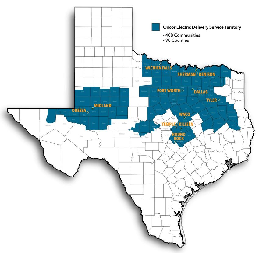
Copyright 2019 Oncor Electric Delivery Company. All rights reserved. Page 9COMPANY SERVICE AREA INFORMATION 100.03 COMPANY SERVICE AREA Copyright 2020 Oncor Electric Delivery Company. All rights reserved. Page 10
SECURITY AND SAFETY INFORMATION

100.04        SECURITY AND SAFETY

100.04.01     Radio and Television Antennas
              Antennas for radio, radio transmitter (including citizen band or amateur), or televisions shall not
              be erected over or under Company’s overhead electric lines, nor shall they be attached to
              Company’s poles or other equipment. Antennas should be located as far as practicable from
              Company’s lines and in a place where they may not accidentally fall into energized wires. To do
              otherwise may result in serious accidents, damage to property or poor radio or television
              reception. The attachment of antenna guying systems to poles carrying Company’s conductors is
              prohibited. Such attachments will be removed upon discovery by Company.

100.04.02     Attachments to Company Facilities
              Company does not permit any unlicensed attachments (such as wires, ropes, signs, banners,
              metering equipment, radio equipment, lightning arresters, alarms, etc.) to Company facilities by
              others except when authorized in writing by Company. Licensed attachments must comply with all
              requirements set forth by Company. License agreements do not allow meter
              equipment to be installed on Company poles if licensee utilization equipment is not on the same
              Company pole. See 500.04, page 41. Company may without notice and without liability remove
              unauthorized attachments to Company facilities. For more information, please contact Oncor's
              Joint Use department at 1.888.313.4747.

100.04.03     Company’s Locks or Seals
              It is standard practice by Company to install locks or seals on all meters, service enclosures,
              service disconnects, pad mounted transformers, pad mounted switchgear, unmetered service
              wireways, or other equipment. Only Company agents and authorized persons shall remove a
              seal or lock. See 500.02, page 40. See “Important Notice Regarding Removal of Oncor Meters to
              Perform work on Customer’s Premise” printed inside front cover of this booklet.

100.04.04     Tampering
              Tampering with Company equipment or using any method which permits the flow of
              unmetered energy to a premise violates the laws of the State of Texas and may lead to
              disconnection of service, prosecution, or both. Company shall not be liable to Customer for any
              injuries or damages that result from such tampering.

Copyright 2019 Oncor Electric Delivery Company. All rights reserved.                                      Page 11
STANDARD DELIVERY SERVICE INFORMATION
100.05 STANDARD DELIVERY SERVICE
100.05.01 General
Company provides delivery service at the Company’s standard voltages in accordance with
Company’s facilities extension policy, and not all standard voltages are available at every location.
If Customer requests a voltage which is non-standard or not available for a specific load or
location, such voltage may be provided by Company at the Company’s discretion and at the
expense of the requesting party. Company does not guarantee that facilities providing
non-standard service (e.g., transformers) are readily available and extended outages may result.
100.05.02 Standard Secondary Voltages
Single-Phase Three-Phase
120 2W --- ---
--- --- 120/208 4W,Y
120/240 3W 120/240 4W, Δ
240 2W 240 3W, Δ
240/480 3W 240/480 4W, Δ
--- --- 277/480 4W,Y
480 2W 480 3W, Δ
2400* 2W 2400* 3W, Δ
--- --- 2400/4160* 4W,Y
--- --- 4160* 3W,Y
*See Company for metering requirements for these voltages
All four-wire services require three load bearing conductors and an NEC compliant
neutral.
100.05.03 Request for Ungrounded Three-Wire, Three-Phase Service
The use of three-wire, three-phase service at 240 V, 480 V and 2400 V, shall be grounded unless
the Customer requests, in writing, that the service be ungrounded (i.e. one service conductor is
grounded at the distribution transformer and at the Customer’s premises grounding electrode
system). See 500.06.07, page 43 for meter sockets used on ungrounded services. Contact
Company representative for details. The use of three-wire, three-phase service at 240 V and 480 V
is only available from overhead transformers. The use of three-wire, three-phase service at 2400 V
is available from overhead and pad mounted transformers in limited size ranges. New or existing
Customers adding load should check with the appropriate Company representative on availability
of service at 2400 V from overhead or pad mounted transformers.
100.05.04 120/208 V, Single-phase, Three-Wire Network Service (Non-Standard)
When and if available, Secondary Service Customers requesting 120/208 V, single-phase,
three-wire service from Company Network Distribution systems in downtown Dallas and
downtown Fort Worth are limited to service entrance capacity of 60 amperes. See 100.05.01 and
Figure 5-I, page 68. For services greater than 60 amperes, the Customer must wire for full
four-wire, wye service.
Copyright 2019 Oncor Electric Delivery Company. All rights reserved. Page 12STANDARD DELIVERY SERVICE INFORMATION (cont'd)
100.05.05 Non-Network Secondary Service Customers
Requesting 120/208 V, single-phase, three-wire service from Company distribution systems may
be limited based upon the existing Company facilities that must be reviewed for each location
requested. If Customer load is greater than 200 amperes, Customer must wire for full four-wire,
wye service. This applies to both overhead and underground services. Refer to 100.05.01, page 12
and Figure 5-I, page 68.
100.05.06 Mixed Use Customer Facilities
Three-phase service for mixed use customer facilities (i.e. residential and commercial) shall be
treated as Secondary Service. The point of delivery for such services shall be as specified in
Drawings on pages 46-53.
100.05.07 Easements, Rights-of-Way, Suitable Space, and Point of Delivery (POD) Requirements
Customer’s electrical installation must be arranged so that the location of the point of
delivery allows Company to provide safe and reliable delivery service, taking into
consideration the location of existing Company facilities and construction needed to
connect Customer’s electric installation to Company system. Customer must grant or secure for
Company, at Customer’s expense, any rights-of-way or easements on property owned or
controlled by Customer necessary for Company to install delivery system facilities for the sole
purpose of delivering electric power and energy to Customer. Customer must provide, without
cost to Company, suitable space on Customer’s premises for the installation of delivery system
facilities necessary to deliver electric power and energy to Customer and for installation of
Company’s metering equipment and the meter. This location must allow for safe and
reliable delivery of service. Company may inspect Customer provided space before installing
electric facilities.
Any change from the Company designated point of delivery (POD) is subject to payment by
customer based on any added costs to reach the new designated point.
To obtain standards on suitable space, Easement and/or Right-of-Way requirements, contact
Company Representative.
100.05.08 Loads Exceeding 3000 Amperes
Standard delivery service at 600 volts and less may be limited to 3000 amperes of load through a
single Customer owned service entrance. Company may require loads exceeding 3000 amperes to
be served with two or more adjacent services at one POD with totalized metering.
100.05.09 Customer’s Electrical Load and Parallel Operation
Customer must take reasonable actions to control the use of electric power and energy so that
Customer’s electrical load at the point of delivery is in reasonable balance and Customer's parallel
operation meets the contractual conditions of the interconnection agreement.
100.05.10 Sensitive Equipment Protection
Customers planning the installation of electric equipment such as computers, communication
equipment, electronic control devices, motors, etc., the performance of which may be adversely
affected by voltage fluctuations, distorted 60 hertz wave forms, or single-phase events are
responsible for providing and installing the necessary facilities, including protective equipment, to
limit these adverse effects.
100.05.11 Three-Phase Service Four-Wire, 120/240 V
Service at 120/240 Volt three-phase, Four-wire delta is available from overhead transformers.
Availability of this service voltage from pad mounted transformers is very limited. New Customers
or existing Customers adding load should check with Company regarding availability of four-wire,
120/240 V, three-phase service from a pad mount transformer.
Copyright 2019 Oncor Electric Delivery Company. All rights reserved. Page 13SECTION 200
CLEARANCES
200.01 Texas Law & OSHA Regulations
To ensure safety and the protection of the public, Chapter 752 of the Texas Health and Safety
Code makes it unlawful for unauthorized persons to move or be placed or bring any part of a
tool, equipment, machine, or material within proximity of live overhead high voltage lines. OSHA
Regulations also restrict the activities of unauthorized persons. See back cover for more details.
Contractors and owners are legally responsible for the safety of construction workers
under this law. This law carries both criminal and civil liability. The Oncor document Safety
Smart provides additional information and may be found at website:
oncor.com/EN/Pages/SafetySmart.aspx. For lines to be turned off, moved, or other
arrangements, call Oncor at 1.888.313.6862
200.02 Local Codes
Some local Electrical Codes require structures to be located a safe distance away from live
overhead high voltage lines as defined by the National Electrical Safety Code.
200.03 Clearances for Service Drop
See Figure 2-A, page 15.
200.04 Clearances of Swimming Pools from Overhead Facilities
Before installation of a pool, contact Company to review clearances to overhead facilities. See
Figure 2-B, pages 16-17 and Table 2-B, page 18.
200.05 Clearances of Swimming Pools from Underground Facilities
Before installation of a pool, contact Company to review clearances to underground facilities. See
Figure 2-C, page 19.
200.06 Clearances of Pad Mounted Transformers from Buildings
pad mounted transformers shall be installed to meet the spatial separations to buildings set forth
in Figure 2-D, page 20. No transformers shall be installed within the drip line of a building unless
installed in a transformer vault meeting the requirements of Article 450 of the National Electrical
Code.
200.07 Screening Clearances around Pad Mounted Equipment
See Figure 2-E, page 21.
200.08 Suitable Space
The required amount of cleared space after vegetation and other obstructions have been
removed in order to access, install, operate, maintain and replace Company facilities. Contact
Company Representative for details.
Copyright 2020 Oncor Electric Delivery Company. All rights reserved. Page 14CLEARANCES OF SERVICE DROP
FIGURE 2-A
6'' Min
Note 5
Notes Notes
6 and 7 1, 2, and 3
Notes
3 and 4
Notes
1 and 2
6' Max
4' Min
Finished Grade
Street / Driveway / Alley. etc.
CLEARANCES FOR SERVICE DROP
Clearances shall be maintained under all varying conditions of wind, temperature and ice loading.
Allowance should be made for change in conductor sag due to varying temperature, wind and ice loading
on the conductor. See Table 3-C, page 26 for minimum service attachment height.
Single-
480D
Phase 240D
Vertical Clearances Single-Phase
120/240 480Y 480
208Y (ft) (ft)
(ft)
Notes:
Over spaces and ways subject to pedestrians or restricted vehicular traffic not
1. exceeding 8 feet In height (see Exceptions below) 12
2. Residential Driveway (see Exceptions below) 16
Alleys, commercial and apartment driveways, parking lots, and other areas
3. subject to truck traffic. 16
4. Streets, highways, county, or other public roads 22
Roof not readily accessible by means of permanent ladder, doorway, ramp, or
5. stairway (service not attached to building, i.e. passing over).* 3.5
6. Roof within 6 feet of mast where mast is within 4 feet of nearest roof edge 1.5
7. Over roof of building service is attached to and roof is not readily accessible. * 3
EXCEPTIONS: listed below are related to Vertical Clearance Notes 1 & 2 for Insulated cables and where height of residential
building does not permit above values. Prior approval by Company representative is required.
Over spaces and ways for residential service drops subject to pedestrians
Exception 1 10 10.5 12
and restricted traffic not exceeding 8 feet in height.
Over residential driveways only
Exception 2 · Service conductor 12 12.5 16
· Drip loops 10 10.5 16
*A roof, balcony, or area is considered readily accessible to pedestrians if it can be casually accessed through a doorway, ramp,
window, stairway, or permanently mounted ladder by a person on foot who neither exerts extraordinary physical effort nor
employs tools or devices to gain entry. A permanently mounted ladder is not considered a means of access if its bottom rung is 8
feet or more from the ground or other permanently installed accessible surface.
HORIZONTAL CLEARANCES
Service drop conductors attached to a building shall not pass closer than 3 feet from windows, wall projections, fire escapes,
balconies or similar locations.*
Copyright 2019 Oncor Electric Delivery Company. All rights reserved. Page 15CLEARANCES OF SWIMMING POOLS FROM OVERHEAD FACILITIES
FIGURE 2-B
Conductors shall not be located directly b
above the pool.
a a
c See Detail "Z" c
Pool
Detail "Z" Figure 1
See Note A
Radius
point
10'
10' Conductors shall not be located directly
above the pool. b
a
c See Detail "Z" c
Pool
Figure 2
See Notes A and B
Notes:
A. Dimensions for "a", "b", and "c" shown above are defined by table on Page 18.
B. Figure 2 shall be applied ONLY to:
· Overhead Guys:
· Neutral Conductor;
· Cabled Conductor ≤ 750 V Phase to Ground
Copyright 2019 Oncor Electric Delivery Company. All rights reserved. Page 16CLEARANCES OF SWIMMING POOLS FROM OVERHEAD FACILITIES (cont'd)
FIGURE 2-B
Conductors shall not be located directly
above the pool.
a a
c c
Ladder
Above ground swimming pool without a deck. Clearances maintained from the highest
point of the installation.
Figure 3
See Notes A and C
10' 10'
Conductors shall not be located directly
above the pool.
a a
c c
Ladder
Above ground swimming pool without a deck. Clearances maintained from the highest
point of the installation.
Figure 4
See Notes A, B, and C
Notes:
A. Dimensions for "a" and "c" shown above are defined by table on Page 18.
B. Figure 4 shall be applied ONLY to:
· Overhead Guys:
· Neutral Conductor;
· Cabled Conductor ≤ 750 V Phase to Ground
C. Proper respective clearances must be maintained if a diving platform, tower, water slide, or other fixed,
pool-related structure exists.
Copyright 2019 Oncor Electric Delivery Company. All rights reserved. Page 17CLEARANCES OF SWIMMING POOLS FROM OVERHEAD FACILITIES (cont'd)
TABLE 2-B
The table below contains clearance values based upon the requirements of the National Electrical Safety
Code with allowances for worst case conditions. Actual clearance requirements vary with conductor size and
type, ambient air temperature, and other factors. The values shown in the table are meant to be a guideline.
When clearances are less than indicated in the table, the Customer should contact Company for exact
requirements based on field conditions.
Please Note: Wires, conductors, cables, or unguarded rigid live parts shall not pass over a swimming pool.
Overhead Bundled or Open Wire Pole Line or
Guy or Cabled Secondary Primary
Requirements Neutral Secondary or Service Conductor
(ft) or Service (ft) (ft)
(ft)
Clearance in any direction from water level, edge
a. of pool, base of diving platform, or anchored raft. 27 27.5 28 30
Clearance in any direction to diving platform,
b. tower, water slide or other fixed, pool related 19 19.5 20 22
structure.
Vertical clearance over adjacent land which is
driveways, parking lots, and alleys subject to
c. truck traffic (any vehicle exceeding 8 feet in 20.5 21 21.5 23.5
height).
Vertical clearance over adjacent land which is
d. spaces and ways subject to pedestrians or 14.5 17 17.5 19.5
restricted traffic only. *
These clearances do not apply to overhead guys,
neutral conductors and cabled conductor ≤ 750
volts when these facilities are 10 feet or more
e.
horizontally from the edge of the pool, diving 10 - - -
platform, diving tower, water slide, or other fixed,
pool related structure.
Copyright 2019 Oncor Electric Delivery Company. All rights reserved. Page 18CLEARANCE OF SWIMMING POOLS FROM UNDERGROUND FACILITIES
FIGURE 2-C
Property Line
Underground Electric Supply
(Riser, Pole, Transformer, etc.)
10' Minimum
Note 3
Locus of 5' Min. Radial Distance
From Pool and Aux. Equipment
Note 1-4 Pool
5'
5'
Aux.
Equipment
Service Lateral
Approximately 3'
Notes:
1. A swimming pool or its auxiliary equipment or water pipes shall not be installed within 5 feet of
direct-buried service lateral cables.
2. Where a swimming pool must be installed within 5 feet of existing direct-buried service lateral cables, the
service lateral cables shall be installed in continuous conduit from the service connection point to the
meter.
3. Conduits installed for Company conductors shall be a minimum of 2 feet from the water’s edge of the
swimming pool. This distance applies to new pool site conduits and to the re-routing of existing electric
service laterals.
4. The swimming pool auxiliary equipment conduits, conductors, water pipes, or customer owned facilities
may not be installed in the same trench as the Company service lateral.
5. Pad mounted equipment shall be located 10 feet or more from the water’s edge.
6. Local requirements may require greater clearances.
7. For swimming pool clearances to overhead facilities, see Figure 2-B, pages 16-17 and Table 2-B, page 18.
8. For additional information related to electric service laterals and swimming pools see document DDS1PR
at Oncor.com.
Copyright 2020 Oncor Electric Delivery Company. All rights reserved. Page 19CLEARANCES OF PAD MOUNTED TRANSFORMERS FROM BUILDING
FIGURE 2-D
Fire Escape
Note 4 A Note 4
Fabricated Secondary
Oil Containment
Transformer Pad
A
Plan View
Window or Ventilating Duct
Transformer
Note 7
Note 6
Note 6 Note 6 Fire Escape
Fabricated Secondary Elevation View
Oil Containment
Note 2
Building Construction Windows,
Transf. Fire Note 7
Fire Resistive Doors and Escapes
Type Non-Fire Resistive Vents Building or
Note 3
Structure
1 Phase 5 ft. 10 ft. 10 ft. 20 ft.
3 Phase 5 ft. 15 ft. 15 ft. 20 ft. Note 6
Clearance Table
Detail A - A
Fabricated Secondary
Oil Containment
Notes:
1. Clearance from building walls shall comply with the clearance table. All dimensions are minimal
dimensions.
2. Where there are building eaves or overhangs within 25 feet above ground, clearance shall be measured
horizontally beginning from the edge of the eave or overhang.
3. Fire resistive building walls include brick and masonry structures that have a 2 hour fire rating.
4. Clearance to building doors, windows, vents and fire escapes to be measured radially.
5. Liquid flow in area surrounding transformer should be away from building. Where ground is flat or slopes
toward building, a fabricated secondary oil containment sufficient to contain all transformer oil for
transformers 500 KVA and larger shall be provided.
6. Clearances are measured from pad edge to building wall, opening, overhang or fire escape unless a
fabricated secondary oil containment device is utilized.
7. Clearances from windows and vents above transformer are measured radially from closest point on
transformer.
8. Pad mounted transformers shall be positioned such that hotstick use is not required on the side facing the
building. If hotstick use is required on the building side, clearances shown in Figure 2-E, page 21 shall be
maintained.
9. There should not be any above ground obstructions, such as shrubs, cooling towers, gas meters, fencing,
etc. within 10 feet of pad or overhangs above pad facilities. Reference Figure 2-E, page 21 for screening
clearances around pad mounted equipment.
10. There should not be any piping or conduit under the pad. (Exception: Mutually agreed upon
communication conduits other than those entering the transformer).
11. Transformers shall not obstruct fire lane.
12. It is the owner’s responsibility to comply with any insurance regulations affecting the premises.
Copyright 2020 Oncor Electric Delivery Company. All rights reserved. Page 20SCREENING CLEARANCES AROUND PAD MOUNTED EQUIPMENT
FIGURE 2-E
Building Wall
Note 1
Screening Wall
Screening Wall
Equipment
5' 5'
Pad
Note 1 Notes 3 & 4 Note 1
10'
Note 1
Note 2
Notes:
1. Clearances to building walls shall be the greater of:
a. The clearances listed in Figure 2-D, page 20 for oil filled equipment
b. 10 feet on operating side
c. 5 feet on non-operating side
2. Gate shall open outward and the width shall be no less than 10 feet.
3. Where ground is flat or slopes toward building, fabricated secondary oil containment sufficient to contain
all oil for transformers 500KVA or larger shall be installed. Contact Company Representative for details.
4. When transformers are installed, screening walls shall provide adequate ventilation.
Copyright 2020 Oncor Electric Delivery Company. All rights reserved. Page 21SECTION 300
OVERHEAD SERVICE INFORMATION
300.01 General
Company provides, installs, and maintains service drop to point of delivery approved by Company.
Customer provides point of attachment which is acceptable to Company so that service drop
meets requirements of all applicable codes.
300.02 Typical Permanent Service Drop
See Figure 3-A, page 24.
300.03 Overhead Service Attachments
See Figure 3-B, page 25.
300.04 Maximum Service Drop Length for Residential Services
See Table 3-C, page 26.
300.05 Overhead Service, with Service Mast
See Figure 3-D, page 27.
300.06 Overhead Service, Permanent Meter Pole
See Figure 3-E, page 28.
300.07 Overhead Service, Wall Mount Meter
See Figure 3-F, page 29.
300.08 Overhead Service, Two or Three Secondary Service Meters
See Figure 3-G, page 30.
300.09 Overhead Service, Four or More Secondary Service Meters
See Figure 3-H, page 31.
300.10 Overhead Service, Three-Wire Delta
See Figure 3-I, page 32.
Copyright 2019 Oncor Electric Delivery Company. All rights reserved. Page 22OVERHEAD SERVICE INFORMATION (cont'd)
300.11 Overhead Service to Mobile or Manufactured Homes
Overhead service to a mobile home shall be made in a manner as depicted in Figure 3-E,
page 28 with a permanent meter pole. The meter socket shall not be mounted directly to
the mobile home. Manufactured homes, if equipped with factory installed service
equipment, may be connected directly if all three of the following requirements are met.
1. The manufactured home is secured to a permanent foundation by an approved
anchoring system. Compliance with this requirement may be evidenced with one of
the following:
a. The manufactured home structure is included in the real property deed
b. The foundation and anchoring system is designed by a Texas licensed engineer or
Texas licensed architect, or
c. An affidavit from a home inspector is provided verifying that the foundation and
anchoring system meets the Texas Administrative Code foundation and anchoring
requirements for Manufactured Housing (TAC Title 10, Part 1, Chapter 80).
2. The service equipment complies with Article 230 of the National Electrical Code (NEC).
3. Bonding and grounding comply with Article 250 of the NEC. Manufactured home
installations that meet the above requirements may be served as depicted in Figure 3-D,
page 27. Service mast shall be of sufficient strength to support service drop. Contact Company
representative prior to installation of mobile or manufactured homes to determine service
method.
300.12 Other Overhead Services
For any situation that is not addressed, please contact Company representative for specific
instructions.
Note: For temporary overhead service, see Section 600, page 71 and Figure 6-A, page 72.
Copyright 2019 Oncor Electric Delivery Company. All rights reserved. Page 23TYPICAL PERMANENT OVERHEAD SERVICE DROP
FIGURE 3-A
1
4
3
Service Drop Terminal Point
2
5 10
Service 6 9
Entrance
Equipment
7 8 Grounding Rod
6' Max
Conductor
4' Min
Approved
Final Grade
Ground Rod
Notes:
1. Service drop (conductors, service grips and service connectors) owned, installed and connected to service
entrance conductors by Company.
2. See Table 3-C, page 26 for maximum length of residential service drop. For all other services contact
Company for maximum service lengths. Reduced distance or higher attachment point may be required for
large service or to maintain minimum clearances.
3. Customer installs service drop attachment of adequate strength for attachment of Company’s service drop
conductors. See Figure 3-B, page 25.
4. Service entrance conductors (#8 Copper or #6 Aluminum minimum) provided and installed by Customer,
shall extend 24 inches or the minimum length required by local ordinance outside the service head for
connection to service drop. Phase conductors to have black insulation. Neutral conductor to be marked
white or bare.
5. Service raceway and service entrance conductors to be owned, maintained, and installed by Customer.
6. Meter socket shall be provided, installed and maintained by Customer. Mounting height to Center is 4 feet
minimum and 6 feet maximum, as measured from finished grade. See Table 5-C, pages 54-59 for list of
approved meter sockets.
7. Customer’s installation to meet the requirements of all applicable codes and local ordinances.
8. Customer’s ground rod conductor (#6 Copper minimum) shall originate in the service entrance equipment
and extend to an ground rod. The ground rod conductor is permitted to be routed through the meter socket
enclosure, but shall not terminate within. Company reserves the right to refuse installation of service upon
observing an unsafe Customer connection. Ufer grounds are not recognized as an approved grounding
electrode.
9. Insulated conduit bushings are required for raceways terminating in the meter socket.
10. The use of flexible metallic conduit, liquid-tight flexible metallic conduit, and liquid-tight flexible
non-metallic conduit for service entrance raceway is prohibited
11. For 3-wire delta services, see Figure 3-I, page 32.
Copyright 2019 Oncor Electric Delivery Company. All rights reserved. Page 24OVERHEAD SERVICE ATTACHMENTS
FIGURE 3-B
Mast Attachement
Note 1
Drip Loop Typ. 4" Steel Angle
Note 3 Minimum
Mast Note 3
Rafter Attachement
Note 1 & 2
3/8" to 1/2"
Diameter
Rafter End
5/8" Eyebolt
Wall
Rafters
Notes:
1. Customer provides and installs service drop attachment of adequate strength for attachment of
Company’s service drop conductors.
2. Screw-in type service attachments are not allowed.
3. Service mast supporting service drop to be minimum 2 inch rigid steel or 2.5 inch IMC conduit with no
coupling above top conduit clamp. EMT is not acceptable for service mast.
4. See Figure 3-I, page 32 for three-wire delta services.
Copyright 2019 Oncor Electric Delivery Company. All rights reserved. Page 25MAXIMUM OVERHEAD SERVICE DROP LENGTH FOR RESIDENTIAL SERVICES
TABLE 3-C
FOR # 2 ALUMINUM TRIPLEX SERVICE CABLE (Note 2)
MINIMUM GROUND
Minimum Attachment Height and Maximum Length of Service Drop
CLEARANCE REQUIRED (ft)
Attachment Height (ft)
10 (Note 3) 12 11 10.5 (Notes 3 and 5)
100 maximum length 90 maximum length 85 maximum length
Attachment Height (ft)
12 14 13 12
95 maximum length 85 maximum length 60 maximum length
Attachment Height (ft)
16 18 17 16
80 maximum length 70 maximum length 45 maximum length
Notes:
1. See Figure 2-A, page 15 for required clearance for single-phase 120/240 V service drop.
2. Distances based on #2 Aluminum triplex service drop. Contact Company representative for requirements
on larger or longer services.
3. Prior approval by Company is required before the exceptions on Figure 2-A, page 15 may be considered.
4. Contact Company representative regarding commercial services or any service over 100 feet in length.
5. Attachment height of 10.5 feet is based on 6 inch allowance of drip loop below attachment point and the
drip loop maintaining 10 feet clearance requirement.
6. Clearances and maximum lengths are based on service attachment to pole at 22 feet 3 inches.
Copyright 2019 Oncor Electric Delivery Company. All rights reserved. Page 26OVERHEAD SERVICE MAST
FIGURE 3-D
Notes:
1.Service drop provided and installed by Company.
2.Customer installs service drop attachment of
adequate strength for attachment of Company's
8 service drop conductors. See Figure 3-B, page 25.
3. Meter socket shall be provided, installed and
1 maintained by Customer. Transockets, when
6" Min 2 required, shall be provided by Company and
installed and maintained by Customer. Socket must
be securely anchored to wall.
12 4. Service mast shall be of sufficient height for the
4
See Fig 2-A pg 15 service drop to meet minimum clearances (see
and Table 3-C pg 26 Figure 2-A, page 15). A minimum 2 inch rigid steel
4 conduit with no coupling above conduit clamp is
5
required. EMT/PVC is not acceptable for service
mast. Service mast to be of sufficient strength to
6 support service drop.
5. Mast roof kit installed by Customer.
4 6. Install a 2 inch x 6 inch between rafters to reinforce
7 roof decking for additional mast support.
3 11 7. Install a conduit hanger above meter socket for
mast support.
8. Service entrance conductors (#8 Copper or #6
Aluminum minimum) provided and installed by
4' Min Customer, shall extend 24 inches or the minimum
10 length required by local ordinance outside of
6' Max
service head for connection to Company service
drop. Phase conductors to have black insulation.
Neutral conductor to be marked white or bare.
9. Customer's installation to meet requirements of all
Finished Grade applicable codes and local ordinances. Typical
single-phase service shown here. For three-phase
see Figure 3-F, page 29.
10. Customer’s ground rod conductor, #6 Copper minimum shall originate in the service entrance equipment
and extend to a ground rod. The ground rod conductor is permitted to be routed through the meter
socket enclosure, but shall not terminate within. Company reserves the right to refuse installation of
service upon observing an unsafe Customer connection. Ufer grounds are not recognized as an approved
grounding electrode.
11. Insulated conduit bushings are required for raceways terminating in the meter socket. See Table 5-C,
pages 54-59 for list of approved meter sockets.
12. Customer shall install additional mast support (guying or other suitable support) to support the tension of
the service drop cable if the service drop attachment (Note 2) is more than 5 feet above the roof line.
13. The use of flexible metallic conduit, liquid tight flexible metallic conduit, and liquid tight flexible
non-metallic conduit for service entrance raceway is prohibited.
14. See Figure 3-I, page 32 for three-wire delta services.
Copyright 2020 Oncor Electric Delivery Company. All rights reserved. Page 27OVERHEAD SERVICE, PERMANENT METER POLE
FIGURE 3-E
1 2 Notes:
6" Min
1. Service drop provided and installed by Company.
2. Customer installs service drop attachment of adequate strength
for attachment of Company's service drop conductors. See Figure
3-B, page 25.
4 3. Meter socket shall be provided, installed and maintained by
Customer. Transockets, when required, shall be provided by
11 12 Company and installed and maintained by Customer. Socket must
be securely anchored.
3 10 4. Service entrance conductors (#8 Copper or #6 Aluminum
minimum) and service raceway provided and installed by
Customer, shall extend 24 inches or the minimum length required
See Fig 2-A pg 15
and Table 3-C pg 26
by local ordinance outside service head for connection to
Company service drop. Phase conductors to have black insulation.
Neutral conductor to be marked white or bare. Customer will bond
4' Min 480 V neutral conductor to all metal service entrance raceways.
6' Max 5. Customer to provide and install support for service attachment
5 and meter socket. Creosote pole or equal to be 5 inch minimum
7 diameter at top. Steel pipe to be 4.5 inch minimum outside
diameter and a minimum thickness of 0.237 inches. Steel tube to
be 4 inches square and a minimum thickness of 0.25 inch. Support
8 to be sufficient height for the service drop to meet minimum
clearances. See Figure 2-A, page 15.
Final Grade 6. Wood Pole to be set in 4 feet of concrete where soil conditions are
less than rock. Steel pipe or tube to be set in 4 feet of concrete.
Ground Pole foam back-fill may be used, if approved by Company.
6 Rod
7. Weatherproof service switch or breaker panel is required for all
Concrete permanent meter pole installations and is provided and installed
by Customer.
8. Customer’s ground rod conductor, #6 Copper minimum shall originate in the service entrance equipment
and extend to a ground rod. The ground rod conductor is permitted to be routed through the meter
socket enclosure, but shall not terminate within. Company reserves the right to refuse installation of
service upon observing an unsafe Customer connection. Ufer grounds are not recognized as an approved
grounding electrode.
9. Customer’s installation to meet the requirements of all applicable codes and local ordinances.
10. Insulated conduit bushings are required for raceways terminating in the meter socket. See Table 5-C,
pages 54-59 for list of approved meter sockets.
11. The use of flexible metallic conduit, liquid tight flexible metallic conduit, and liquid tight flexible
non-metallic conduit for service entrance raceway is prohibited. The service raceway may not contain any
condulet or other open connections.
12. The use of schedule 40 or 80 PVC for service mast not supporting service drop is allowed unless prohibited
by the local inspecting authority. Service mast shall be of sufficient height for the service drop to meet
minimum clearances (see Figure 2-A, page 15). A 2 inch rigid steel minimum with no coupling above
conduit clamp is required. EMT/PVC is not acceptable for service mast. Service mast to be sufficient
strength to support service drop.
13. For overhead service to mobile homes, see 300.11, page 23.
14. For three-wire delta services, see Figure 3-I, page 32.
Copyright 2020 Oncor Electric Delivery Company. All rights reserved. Page 28OVERHEAD SECONDARY SERVICE, WALL MOUNTED METER
NON-RESIDENTIAL SINGLE OCCUPANCY STRUCTURES
FIGURE 3-F
2 1. Service drops provided and installed by Company
2. Customer installs service drop attachment of adequate
strength for attachment of Company's service drop
conductors. See Figure 3-B, page 25.
1 3. Meter socket shall be provided, installed and
maintained by Customer. Transockets, when required,
4 shall be provided by Company and installed and
7 maintained by customer. Socket must be securely
9 10 anchored to wall.
4. Service entrance conductors (#8 Copper or #6
See Figure 3-C Aluminum minimum) and service raceway provided and
installed by Customer, shall extend 24 inches or the
See Figure 2-A
minimum length required by local ordinance outside
service for connection to service drop. Phase
3 conductors to have black insulation. Neutral conductor
4' Min to be marked white or bare.
8 6' Max 5. Customer's ground rod conductor (#6 Copper minimum)
Three-phase shall originate in the service entrance equipment and
Customer's extend to a ground rod. The ground rod conductor is
Service Switch
permitted to be routed through the meter socket
enclosure, but shall not terminate within. Company
5 reserves the right to refuse installation of service upon
observing an unsafe Customer connection
6. Customer's installation to meet all requirements of all
applicable codes and local ordinances.
7. Two or more conduit straps shall be provided to support conduit. Socket must be securely anchored to wall.
The service raceway may not contain any condulet or other open connections.
8. Insulated conduit bushings are required for raceways terminating in meter socket.
9. The use of flexible metallic conduit, liquid tight flexible metallic conduit, and liquid tight flexible
non-metallic conduit for service entrance raceway is prohibited. The service raceway may not contain any
condulet or other open connections.
10. The use of PVC for service mast not supporting service drop is allowed unless prohibited by the local
inspecting authority. Service mast shall be of sufficient height for the service drop to meet minimum
clearances (see Figure 2-A, page 15). A 2 inch rigid steel minimum with no coupling above conduit clamp is
required. EMT/PVC is not acceptable for service mast. Service mast to be sufficient strength to support
service drop.
11. Not for three-wire delta services, see Figure 3-I, page 32.
12. If an existing single-occupancy structure customer requests that one or more additional three-phase meters
be installed to convert to a multi-metered structure, then the customer must install a disconnecting means
on the load side of each existing three-phase meter installation on the structure and on each newly
installed three-phase meter installation.
13. If there is a possibility of additional customers being served from the same transformer at another location,
a service disconnect is required. This only applies for non-residential installations.
14. Single-phase services that utilize transockets for the metering equipment require a disconnecting means to
be installed on the load side of the transocket. See Figure 5-D, pages 60-63 for instrument rated/transocket
details.
15. Service disconnect switches and breakers are both acceptable for use as the disconnecting means. The
disconnecting means must have provision for a Company lock. The disconnecting means must be readily
accessible by Company and within close proximity of the meter. A 4 inch minimum clearance from the
service disconnect switch operating lever is required. Customer must receive Company approval of
electrical design and/or nonstandard equipment or locations prior to installation of equipment.
Copyright 2019 Oncor Electric Delivery Company. All rights reserved. Page 29You can also read