Service Definition E-Line Service - Nexium Telecommunications
←
→
Page content transcription
If your browser does not render page correctly, please read the page content below
Service Definition
               E-Line Service

                                                                    Standard S003 Ver 2
©Copyright 2004-2018 Nexium Telecommunications ABN 34 106 459 465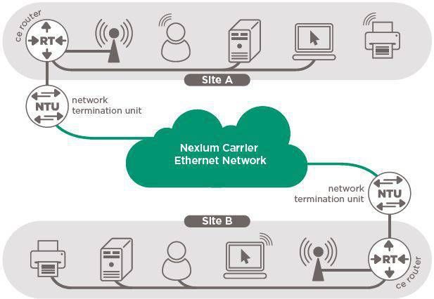
E-Line Service

Contents
1   Overview ...................................................................................................................... 1
    1.1 Introduction.......................................................................................................... 1
    1.2 Product Overview ................................................................................................ 1
2   Service Specification .................................................................................................. 1
    2.1 Transport Options ................................................................................................ 2
    2.2 User Network Interface (UNI) .............................................................................. 2
    2.3 Bandwidth Profile................................................................................................. 3
    2.4 Quality of Service ................................................................................................ 5
3   Access Methods .......................................................................................................... 6
4   Service Levels1 ............................................................................................................ 6
    4.1 Target Service Levels .......................................................................................... 6
    4.2 Severity Level Definitions .................................................................................... 6
    4.3 Service Availability............................................................................................... 7
    4.4 Service Latency ................................................................................................... 8
    4.5 Service Jitter........................................................................................................ 9
    4.6 Service Utilisation ................................................................................................ 9
    4.7 Packet Loss ....................................................................................................... 10
5   Support Service Levels ............................................................................................ 11
    5.1 Incident Management ........................................................................................ 11
    5.2 Change Management ........................................................................................ 12
6   Technical Specifications 2 ........................................................................................ 12
    6.1 UNI Specification ............................................................................................... 12
    6.2 EVC Technical Specification 3 ........................................................................... 14

                                                                                                               Standard S003 Ver 2
                            ©Copyright 2004-2018 Nexium Telecommunications ABN 34 106 459 465
E-Line Service

1 Overview
     1.1 Introduction
This Service Definition describes Nexium’s E-Line product from the customer’s perspective. In this
document the product is described in terms of an overview, service specification, service levels,
orderable service options and technical specifications.

The Product Description details standard aspects of Nexium’s E-Line product. Specific customer
requirements may vary, and therefore any service offering (including aspects such as price and
performance guarantees) will require contractual agreement.

     1.2 Product Overview
The E-Line product is a point-to-point service, which provides for connection requirements of
between 1 Mbps and 10000 Mbps (10 Gbps) using standard Ethernet interfaces. E-Line services
can meet simple requirements where two sites need to be linked, or multiple services can be
configured to provide for connectivity between many sites.

E-Line Services can be configured using flexible, high-speed bandwidth profiles to meet service
performance and capacity requirements. The service also provides quality of service features to
support IP-based transport of voice, video and business critical data communications.

2 Service Specification
As shown in the diagram below, a E-Line Service is comprised of:
              •    User Network Interfaces (UNI) that provides standards-based Ethernet interfaces
                   between Nexium and the Customer Edge (CE).
                        o    CE represents the Customer Edge interface for the EVC service connection.
                        o    UNI Represents the Network Provider’s (Nexium) interface for the EVC
                             service connection.
              •    Ethernet Virtual Connection (EVC) that connects two UNIs in a full duplex, point to
                   point mode. The EVC capacity matches the customer-specified bandwidth profile.

 E-Line Service Definition v7.2.5.docx                                                             Page 1 of 17

                               ©Copyright 2004-2018 Nexium Telecommunications ABN 34 106 459 465
E-Line Service
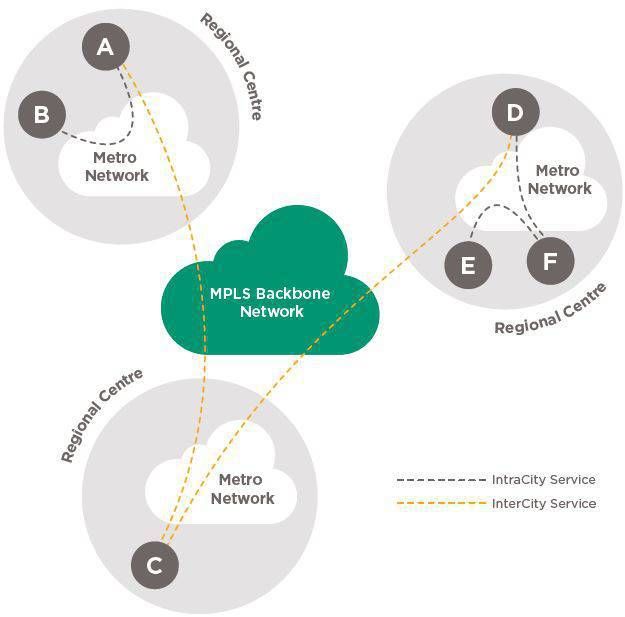
2.1 Transport Options
Nexium operates a number of metro Ethernet networks, and an MPLS backbone network which
covers much of regional Queensland. An E-Line service may be provided as:
• An IntraCity E-Line Service - Ethernet Switched Only Service, which does not
traverse the MPLS backbone network.
• An InterCity E-Line Service - Ethernet over MPLS service, which traverses the MPLS
backbone network.
Ergon and third party wide area transmission services enable Nexium to deliver end-to-end
managed E-Line Services between regional centres. The diagram below shows a number of E-Line
services.
2.2 User Network Interface (UNI)
A customer accesses an E-Line service at the UNI, and the UNI defines the point of service
responsibility between Nexium and the Customer (CE). The physical interface is provided to a
customer as a designated Ethernet port on the Nexium UNI. This switch is provided and maintained
by Nexium, with the cabling between UNI and CE to be provided by the customer.
UNI supported physical interfaces include twisted pair and short or long wavelength optical fibre
according to IEEE 802.3 standards. The physical presentation from the Nexium UNI will be:
• Copper Ethernet - RJ-45 (8P8C keyed) receptacle (IEC 60603-7)
• Optical Fibre – Duplex LC receptacle (IEC 61754-20)
The customer will provide and maintain the appropriate cabling between the UNI and CE
The logical interface is provided at the UNI using IEEE 802.1Q tagged Ethernet frames.
E-Line Service Definition v7.2.5.docx Page 2 of 17
©Copyright 2004-2018 Nexium Telecommunications ABN 34 106 459 465E-Line Service
The customer can choose from the following UNI IEEE 802.1Q tagging options per UNI:
1. S-Tagged Service Interface (default interface option):
a. Nexium provides the customer with an EVC ID (also known as VLAN ID, which is a
part of the S-TAG,) for each E-Line service.
b. Customer must tag all the traffic transmitted to Nexium with S-TAG.
c. Customer selects a Layer 2 control protocol delivery option.
d. Customer can have any inner CE-VLAN (C-TAG) under this S-TAG.
e. Incorrect outer tagged (S-TAG) or untagged frames are not transported across an
EVC.
f. Nexium provides service multiplexing by terminating multiple S-Tagged EVCs on a
single UNI.
2. C-Tagged Service Interface:
• Nexium by default maps all customer traffic entering UNI to a single EVC ID (S-TAG).
• Customer can forward any IEEE 802.1Q tagged frames.
• Customer selects a Layer 2 control protocol delivery option.
• Customer can forward untagged frames.
• Nexium can optionally provide service multiplexing by mapping different CE-VLANs to
separate EVCs.
The customer can choose from the following Layer 2 control protocol delivery options:
1. Layer 2 control protocol frames discarded
2. Layer 2 control protocol transported: cdp, lldp, stp, vtp, pagp, lacp, udld
2.3 Bandwidth Profile
E-Line service bandwidth is specified using two traffic parameters:
• Committed Information Rate (CIR): The rate in bps of ingress service frames that
Nexium delivers between UNIs that meets the CIR rate defined by the relevant traffic
class.
• Excess Information rate (EIR): The rate in bps of all ingress service frames that
Nexium delivers between UNIs. This includes CIR compliant frames.
• Mark Down Traffic Rate: The amount of traffic that is not discarded that exceeds
CIR that is calculated as (EIR-CIR).
The CIR and EIR parameters together define the bandwidth profile for the service. The customer
selects CIR and EIR on the basis of traffic classes (refer to Quality of Service below).
The customer:
• Selects a CIR for each traffic class. The customer is required to select at least one of
Real Time, Business Critical or Bulk Data class for each service. The default traffic class,
if undefined in the commercial agreement, is Bulk Data.
• Defines the Service CIR as the sum of all selected traffic class CIRs for the service, up to
a limit of the UNI access speed.
E-Line Service Definition v7.2.5.docx Page 3 of 17
©Copyright 2004-2018 Nexium Telecommunications ABN 34 106 459 465E-Line Service
• Defines the Service EIR as greater than or equal to the Service CIR, up to the limit of the
UNI access speed.
• Note:
o the Real Time traffic class is not permitted to transmit above the defined CIR.
o for Ethernet Switched Only services, Service EIR is required to be equal to the
Service CIR.
• Calculation of both CIR and EIR bandwidth is based on use of 1526 byte frames,
including all underlying carrier and protocol overheads.
The service bandwidth profile is specified using the parameters shown in the tables below.
Table 1: Service Types
Service Type Minimum CIR Above Minimum CIR EIR
Nexium EVC 1 Mbps • < 10 Mbps: Increments of 1Mbps to 10 • < 10 Mbps: Increments of
Mbps 1Mbps to 10 Mbps
• < 100 Mbps: Increments of 10 Mbps to 100 • < 100 Mbps: Increments of 10
Mbps Mbps to 100 Mbps
• > 100 Mbps: Increments of 50 Mbps to • > 100 Mbps: Increments of 50
1000 Mbps Mbps to 1000 Mbps
• > 1000 Mbps (1 Gbps) : Increments of 500 • > 1000 Mbps (1 Gbps) :
Mbps to 10000 Mbps (10 Gbps) Increments of 500 Mbps to
10000 Mbps (10 Gbps)
Table 2: Bandwidth Profiles
Bandwidth Profile
Per Service Class CIR EIR
RT Class ¹ RTc RTc
BC Class BCc Se ²
BD Class BDc Se ²
Per Service Aggregate Bandwidth Profile
Service CIR RTc + BCc + BDc
Shared EIR Se
Service EIR RTc + Se
1
CIR = EIR for RT
2
EIR Value is shared across BC and BD classes.
The following principles apply:
• The Real Time class EIR always equals CIR.
• The EIR is common for Business Critical and Bulk Data (i.e. Shared EIR)
• The Real Time class does not form part of the shared EIR.
• The aggregate Shared EIR is established by removing the Real Time CIR from the total
Service EIR.
• For the shared EIR product the traffic rates are expressed as CIR/EIR where EIR is
expressed as the maximum rate that the class can be transmit at. Due to the nature of
the shared EIR product, all shared EIR classes will have the same EIR.
• Aggregate traffic received in Shared EIR classes greater than the Shared EIR rate will be
dropped indiscriminately.
E-Line Service Definition v7.2.5.docx Page 4 of 17
©Copyright 2004-2018 Nexium Telecommunications ABN 34 106 459 465E-Line Service
• For Business Critical and Bulk Data classes, any traffic that is transmitted at or above the
CIR rate of respective individual class will be re-marked and is only subject to the SLA for
the Mark Down class. The traffic at or below the CIR of the respective individual class is
subject the SLA for that class.
• The traffic that has been remarked will be considered as discard eligible, and may be
discarded in the event there is congestion on the EVC path.
• Only a specific class can use its own CIR bandwidth as CIR.
Table 3: Traffic Classes
Traffic Customer Customer Application Supported Service Levels
Class DSCP Class of Guidelines
Throughput Delay Loss Jitter
Service
(CoS)
identifier
Real Time Voice and interactive
EF CoS = 5 video. Yes Yes Yes Yes
Business Transactional and
Critical interactive applications
AF21 & AF23 CoS = 2 Yes Yes Yes No
with a high business
priority.
Large file-transfers, e-mail,
network backups,
database syncs and
Bulk Data All Else All Else Yes Yes Yes No
replication. Default class
for all unassigned traffic
within CIR.
Mark N/A
N/A CoS = 0 No No No No
Down
Untagged customer frames that do not have COS value will be transported as the lowest purchased
Traffic Class. If the customer selected the option to transport Layer 2 Control traffic (eg: CDP, STP,
etc.) this will always be transported as Business Critical.
When selecting CIR and EIR bandwidth parameters for traffic classes, the following guidelines
should be utilised. These guidelines define the forwarding rules applied to each traffic class based
on whether the traffic instantaneously exceeds the specified CIR, or exceeds the specified EIR.
Table 4: QoS Actions
Traffic Class EIR Guidelines CIR Exceed Action EIR Exceed Action
Real Time EIR for this class must equal CIR. Discard Discard
Business Critical EIR can be specified up to Service EIR Mark down Discard
Bulk Data EIR can be specified up to Service EIR. Mark down Discard
2.4 Quality of Service
Customers identify the relative importance of their traffic by setting IP Diffserv Code Points (DSCP)
or by setting the COS value in the outer most IEEE 802.1Q Tag at the EVC UNI. Nexium will then
provide class-based quality of service treatment that reflects the relative priority of each traffic class.
Nexium supports three traffic classes, per service, with supported SLA’s for CIR compliant traffic.
Marked down traffic has no supported SLA’s for Throughput, Delay, Packet Loss or Jitter. These
classes and the supported service levels are defined in the table below.
E-Line Service Definition v7.2.5.docx Page 5 of 17
©Copyright 2004-2018 Nexium Telecommunications ABN 34 106 459 465E-Line Service
3 Access Methods
The E-line service may be available over a range of existing access methods offered and/or
supported by Nexium, including:
• Fibre
• Radio / microwave
• Fixed wireless,
• External 3G/4G and DSL
• National Broadband Network (NBN) services, including FTTx and Hybrid-Fibre Coaxial
services, Fixed Wireless and Satellite (SkyMusterTM) services (note – a Fair Use Policy
applies to NBN Satellite services).
Full details of connectivity options and technical requirements are outlined in the Technical
Specifications section of this document.
4 Service Levels1
Service Levels determine the quality characteristics of the Services. Service levels are described in
terms of individual metrics, as outlined in the tables below. Specific customer requirements may
vary, and therefore any service offering (including aspects such as price and performance
guarantees) will require contractual agreement.
Where external providers are used, such as 3G/4G, DSL and NBN services, service levels may vary
outside Nexium’s standard resolution times. This information should be discussed between the
customer and Nexium Account Manager and acknowledged in a specific agreement for each
service.
4.1 Target Service Levels
The Service Level Tables below also include Target Service Levels for some metrics.
4.2 Severity Level Definitions
Some of the Service Level metrics include reference to Severity Levels, being the severity
designation assigned to Incidents. The Severity Levels are defined as follows:
Severity Level 1 – A total loss of a service element or error rate that renders the service
unavailable, or any fault that poses a hazard to the safety of the customer’s or supplier’s
personnel, or the general public.
Severity Level 2 – a partial loss of a service element component; or a reduction in link traffic
carrying capacity (degradation), Service still usable but impaired.
Severity Level 3 – anomalies in transmission performance; or any non-service affecting
alarms.
Severity Level 4 – indicates all other reasonable problems or requests.
E-Line Service Definition v7.2.5.docx Page 6 of 17
©Copyright 2004-2018 Nexium Telecommunications ABN 34 106 459 465E-Line Service
A customer may request that an incident be treated as a higher Severity Level if the customer
reasonably believes that the business impact of the incident is greater than the Severity Level
classification assigned.
1.
Service Level targets are for Nexium managed services only. External services such as 3G/4G, DSL, NBN and satellite services are
subject to service levels provided by the relevant provider.
4.3 Service Availability
Metric: Service Availability
Metric Definition Measures the availability of each E-Line Service.
“Available” in relation to the Service means that the Service is accessible to the customer, and able to
transmit customer data across the Nexium network, as measured at the Measurement Point specified
below. The E-Line service is considered unavailable when the Nexium Operational Support System point
to point service agent reports unavailability of either end.
Availability is measured on a per service basis.
Measurement Period 24x7
Target Service Level 99.95% for service delivery within or between Regional Centres or Brisbane
Applicable Rebate Defined in Service Agreement
Measurement Methodology
Measurement Point Measured from the User Network Interface i.e. the customer’s connection at the Nexium Customer Edge
switch.
Calculation (Actual Hours Available + Excusable Downtime)
Actual Availability % = * 100
Available Hours
Where:
Actual Hours Available means the amount of time within the Available Hours that the Service was
actually Available.
• Downtime will commence on notice from customer.
• Completion of downtime will be based on NOC advising customer service is restored.
Excusable Downtime means the aggregate time within the Available Hours that the Service is not
Available due to:
• any Scheduled Downtime; and
• any other excusable event under the Customer contract. Includes in the first instance Force
Majeure, compliance with laws / direction of a Regulator, Customer or End User caused
outages and suspensions as an alternative to right of termination.
Available Hours means 24 hours, 7 days a week every day of the year.
Period of Calculation Calculated on a calendar monthly basis
Frequency of A service response measurement is taken every 5 minutes.
Measurement
Data Source Measured using Nexium’s Operational Support System.
Reporting Responsibility Network Operations Centre
Reporting Frequency Monthly – to be provided within 10 Business Days of the end of the relevant calendar month.
E-Line Service Definition v7.2.5.docx Page 7 of 17
©Copyright 2004-2018 Nexium Telecommunications ABN 34 106 459 465E-Line Service
Reporting Requirements • Reports to be provided in soft copy
• All relevant support data required to verify the Service Level calculations to be provided or made
available in an acceptable format
• Reports to include the information set out in the “Calculation” section, details of actual performance
against Minimum Service Level (in graphic representation where possible), details of outages, causal
analysis and remedial and preventative actions.
4.4 Service Latency
Metric: Service Latency
Metric Definition Measures the latency of the E-Line Service by measuring User Network Interface to User Network
Interface delay between each Customer Site. Latency is reported for a Service on a one way basis.
Measurement Period 24 x 7
Target Service Level Traffic Class
Real Time Business Critical Bulk Data Mark Down
Inter-City Intra-City Inter-City Intra-City Inter- Intra-
City City
Not applicable
< 30 ms < 10ms < 40ms < 15ms < 50ms < 20ms
Applicable Rebate N/A
Measurement Methodology
Measurement point Between two User Network Interfaces.
Calculation The average of the all sample measurements over the period of calculation.
Period of Calculation Calculated on a calendar monthly basis.
Frequency of Measured at 5 minute intervals.
Measurement
Data Source Measured using Nexium’s Operational Support System.
Measurement Network Operations Centre.
responsibility
Reporting Frequency Monthly – to be provided within 10 Business Days of the end of the relevant calendar month.
Reporting Requirements • Reports to be provided in soft copy
• All relevant support data required to verify the Service Level calculations to be provided or made
available in an acceptable format.
• Reports to be provided on an as required basis. Details of causal analysis and remedial and
preventative actions to be provided.
E-Line Service Definition v7.2.5.docx Page 8 of 17
©Copyright 2004-2018 Nexium Telecommunications ABN 34 106 459 465E-Line Service
4.5 Service Jitter
Metric: Service Jitter
Metric Definition Measures the jitter of the E-Line Service by measuring variation of delay between each Customer Site.
Jitter is reported on a one way basis.
Measurement Period 24 x 7
Target Service Level Traffic Class
Real Time Business Critical Bulk Data Mark Down
< 10 ms Not applicable Not applicable Not applicable
Applicable Rebate N/A
Measurement Methodology
Measurement point Between two User Network Interfaces.
Calculation The average of the all sample measurements over the period of calculation.
Period of Calculation Calculated on a calendar monthly basis.
Frequency of Measured at 5 minute intervals.
Measurement
Data Source Measured using Nexium’s Operational Support System.
Measurement Network Operations Centre
responsibility
Reporting Frequency Monthly – to be provided within 10 Business Days of the end of the relevant calendar month.
Reporting Requirements • Reports to be provided in soft copy
• All relevant support data required to verify the Service Level calculations to be provided or made
available in an acceptable format
• Reports to be provided on an as required basis Details of causal analysis and remedial and
preventative actions to be provided.
4.6 Service Utilisation
Metric: Service Utilisation
Metric Definition Measures the actual bandwidth utilisation of each E-Line Service, reported in graphical format.
Measurement Period 24 x 7.
Target Service Level N/A
Applicable Rebate N/A
Measurement Methodology
Measurement point Measured between two User Network Interfaces.
Calculation Service Utilisation means the actual utilisation measured over the Measurement Period.
Period of Calculation Calculated on a calendar monthly basis.
Frequency of Utilisation measured at 5 minute intervals.
Measurement
Data Source Measured using Nexium’s Operational Support System.
E-Line Service Definition v7.2.5.docx Page 9 of 17
©Copyright 2004-2018 Nexium Telecommunications ABN 34 106 459 465E-Line Service
Measurement responsibility Network Operations Centre
Reporting Frequency As Reasonably required.
Reporting Requirements • Reports to be provided in soft copy
• All relevant support data required to verify the Service Level calculations to be provided or made
available in an acceptable format.
• Reports to be provided on an as required basis Details of causal analysis and remedial and
preventative actions to be provided.
4.7 Packet Loss
Metric: Packet Loss
Metric Definition Measures the percentage of CIR compliant packets lost as a percentage of the total number of CIR
compliant packets sent between two User Network Interfaces.
Measurement Period 24 x 7
Target Service Level Traffic Class
Real Time Business Critical Bulk Data Mark Down
< 0.5% < 1% < 1% Not applicable
Applicable Rebate N/A
Measurement Methodology
Measurement point Measured between two User Network Interfaces.
Calculation
Packet Loss % =
∑ Test packets lost ∗100
∑ Test packets sent
as determined on the average of all measurements over the period of calculation.
Period of Calculation Calculated on a calendar monthly basis.
Frequency of Packet Loss measured at 5 minute intervals.
Measurement
Data Source Measured using Nexium’s Operational Support System.
Measurement Network Operations Centre.
responsibility
Reporting Frequency Monthly – to be provided within 10 Business Days of the end of the relevant calendar month.
Reporting Requirements • Reports to be provided in soft copy.
• All relevant support data required to verify the Service Level calculations to be provided or made
available in an acceptable format.
• Reports to be provided on an as required basis Details of causal analysis and remedial and
preventative actions to be provided.
E-Line Service Definition v7.2.5.docx Page 10 of 17
©Copyright 2004-2018 Nexium Telecommunications ABN 34 106 459 465E-Line Service
5 Support Service Levels
5.1 Incident Management
Metric: Incident Management
Metric Definition Measures the successful completion of incident response, resolution and communication processes for
each problem. Incident management measures the percentage of incidents where response and resolution
targets were met and communication processes followed.
Incident Management targets are a function of the severity of the problem.
Measurement Period 24 x 7
Target Service Levels
Response (By Restoration Communication Updates
Telephone)
(Excludes reasonable
travel time to site
from closest
concentration of the
applicable personnel,
ie: Rockhampton,
Townsville,
Toowoomba for
Regional Centres)
Severity 95% within 30 95% within 4 hours Every 30 minutes
Level 1 minutes
Severity 95% within 30 95% within 8 hours Every 60 minutes
Level 2 minutes
Severity 95% within 30 95% within 5 Once per day
Level 3 minutes business days
Severity 95% within 1 95% within 10 Weekly notification of outstanding problems
Level 4 business day (e- business days or as
mail or otherwise agreed
telephone
response)
Faults that are a result of a fibre cut by the Supplier or the Supplier’s Personnel - 12 hours (excluding
reasonable travel times from Townsville / Rockhampton / Toowoomba to the relevant site)
Faults that are a result of a fibre cut by any person other than the Supplier or the Supplier’s Personnel: -
Force Majeure conditions apply and the Supplier will use best endeavours to restore.
Applicable Rebate N/A
Measurement Methodology
Measurement points N/A
Calculation N/A
Period of Calculation Calculated on a per incident basis
Frequency of Monthly
Measurement
Data Source Nexium Fault Management System.
Measurement Network Operations Centre
responsibility
Reporting Frequency Monthly – to be provided within 10 Business Days of the end of the relevant calendar month.
E-Line Service Definition v7.2.5.docx Page 11 of 17
©Copyright 2004-2018 Nexium Telecommunications ABN 34 106 459 465E-Line Service
Reporting • Reports to be provided in soft copy
Requirements
• All relevant support data required to verify the Service Level calculations to be provided or made
available in an acceptable format
• Reports to include, details of actual performance against Target Service Level (in graphic
representation where possible), details of causal analysis and remedial and preventative actions to be
provided.
5.2 Change Management
Metric: Change Management
Metric Definition Measures successful completion of operational change activities.
Successful completion means a change that has been completed or backed out in accordance with the
agreed change window and process and that does not introduce unforeseen problems subsequent to
implementation of the change.
Scheduled Hours N/A
Minimum Service Level 95% of changes successfully completed in accordance with scheduled change window.
Target Service Level 98% of changes successfully completed in accordance with scheduled change window.
Applicable Rebate N/A
Measurement Methodology
Measurement point N/A
Calculation % = Successful Changes/Total Changes x 100
Period of Calculation Measured for each change.
Frequency of Monthly
Measurement
Data Source Change Management tracking data base and related records.
Measurement Network Operations Centre
responsibility
Reporting Frequency Monthly – to be provided within 10 Business Days of the end of the relevant calendar month.
Reporting Requirements Reports to be provided in soft copy
All relevant support data required to verify the Service Level calculations to be provided or made available
in an acceptable format, including number and reason for planned outage.
6 Technical Specifications 2
6.1 UNI Specification
UNI Attribute Description Parameter
Physical Medium The Ethernet physical media that Interface Options:
deliver EVC service to the customer. • 100BASE-TX Category 5 UTP
Note: Nexium will provision services • 1000BASE-SX Multimode optical fibre
only to the UNI.
• 1000BASE-LX Single mode or multimode optical fibre
• 1000BASE-T Category 5 UTP
• 10GBASE-SR Multimode optical fibre
• 10GBASE-LR Single mode optical fibre
Interface Speed The speed of the Ethernet interface. 100 Mbps, 1000, or 10000 Mbps
Interface Port Type The Ethernet port type. IEEE 802.1Q Trunk
Maximum Frame Size The maximum Ethernet frame size By default 1526 bytes, including 802.1Q header, and excluding
E-Line Service Definition v7.2.5.docx Page 12 of 17
©Copyright 2004-2018 Nexium Telecommunications ABN 34 106 459 465E-Line Service
supported at the UNI. header preamble.
Larger MTU frames may be agreed with customer at the
discretion of Nexium.
Mode The Ethernet mode. Full duplex
MAC Layer The Ethernet MAC Standard. IEEE 802.3-2005
MAC Addresses per UNI The number of customer MAC Maximum per 200 per EVC.
addresses supported per UNI. Additional MAC Addresses per EVC may be agreed at the
discretion of Nexium.
Service ID Nexium defined.
Ingress Bandwidth A bandwidth profile is applied to all No
Profile per Ingress UNI ingress Service Frames at the UNI.
Ingress Bandwidth A bandwidth profile is applied to all No
Profile per EVC ingress Service Frames for an EVC at
the UNI.
Ingress Bandwidth A bandwidth profile is applied to all Yes
Profile by Traffic Class ingress Service Frames with a specific
Traffic Class.
S-Tagged Service Interface
Service Multiplexing A UNI service attribute in which the Yes. The UNI can support multiple EVCs by default.
UNI can be in more than one EVC
instance.
Bundling A UNI attribute in which more than one Yes. More than one customer VLAN can map to an EVC at the
CE-VLAN VLAN ID can be associated UNI. Customer to map CE-VLAN to EVC.
with an EVC.
All-to-One Bundling A UNI attribute in which all CE-VLAN No.
VLAN IDs are associated with a single
EVC.
EVC ID (S-TAG) The Nexium defined service VLAN ID. Nexium defined. Each assigned EVC maps to a unique EVC.
The customer must insert this as the outer most tag.
CE-VLAN / EVC Map An association of CE-VLAN VLAN IDs Customer can optionally use and map CE-VLAN to the Nexium
with EVCs at a UNI defined EVC ID/s.
Untagged frames All untagged frames are discarded. Yes, all untagged frames are discarded.
Number of EVCs per Maximum of 8 for 100 Mbps UNI
UNI. Maximum of 20 for 1000 Mbps per UNI
Maximum of 50 for 10000 Mbps (10Gbps) per UNI
C-Tagged Service Interface
1
Service Multiplexing A UNI service attribute in which the Optional. The UNI supports a single EVC by default .
UNI can be in more than one EVC
instance.
Bundling A UNI attribute in which more than one Yes. More than one customer VLAN can map to an EVC at the
CE-VLAN VLAN ID can be associated UNI.
with an EVC.
All-to-One Bundling A UNI attribute in which all CE-VLAN Optional. All customer VLANs map to a single EVC at the UNI by
VLAN IDs are associated with a single default.
EVC.
E-Line Service Definition v7.2.5.docx Page 13 of 17
©Copyright 2004-2018 Nexium Telecommunications ABN 34 106 459 465E-Line Service
EVC ID (S-TAG) The Nexium defined service VLAN ID. Nexium defined. Each assigned EVC maps to a unique EVC.
Nexium will insert this as the outer most tag.
CE-VLAN / EVC Map An association of CE-VLAN VLAN IDs Customer can use any CE-VLAN. Nexium will map the CE-VLAN
with EVCs at a UNI to the EVC/s.
Untagged frames All untagged frames are discarded. No. All untagged frames will be mapped to one EVC.
Number of EVCs per Default 1
UNI. Maximum of 8 for 100 Mbps UNI
Maximum of 20 for 1000 Mbps per UNI
Maximum of 50 for 10000 Mbps (10Gbps) per UNI
2
Untagged frames are mapped to a single EVC.
6.2 EVC Technical Specification 3
EVC Attribute Description Parameter
EVC Type E-Line (Point-to-point EVC) Point to point
EVC VLAN-ID (S-TAG The VLAN Tag is preserved end to No.
EVC) Preservation end for the service. 802.1Q EVC VLAN ID may be rewritten and may not be
consistent end to end. Nexium and customer will agree VLAN ID
to be used at both ends prior to service initiation.
CoS (S-TAG EVC) An EVC attribute in which the EVC No.
Preservation CoS of an egress Service Frame is CoS bits will be set by Nexium and will be presented to customer
identical in value to the EVC CoS of on egress as per Table 3.
the corresponding ingress Service
Frame
CE-VLAN ID An EVC attribute in which the CE- Yes
Preservation VLAN ID of an egress Service Frame
is identical in value to the CE-VLAN ID
of the corresponding ingress Service
Frame.
CE-VLAN CoS An EVC attribute in which the CE- Yes
Preservation VLAN CoS of an egress Service
Frame is identical in value to the CE-
VLAN CoS of the corresponding
ingress Service Frame
IP DSCP Preservation The customers IP header is preserved Yes
end to end on service.
Unicast Service Frame Frames with a unicast destination Deliver unconditionally.
Delivery MAC address.
Multicast Service Frame Frames with a multicast destination Deliver conditionally.
Delivery MAC address. Condition: Frame does not violate multicast storm control levels.
E-Line Service Definition v7.2.5.docx Page 14 of 17
©Copyright 2004-2018 Nexium Telecommunications ABN 34 106 459 465E-Line Service
Broadcast Service Frames with a broadcast destination Deliver conditionally.
Frame Delivery MAC address. Condition: Frame does not violate broadcast storm control
levels.
Layer 2 Control Protocol Frames used in Layer 2 control plane, Optional. Deliver the following L2 protocol tunneling
Service Frame Delivery e.g., Spanning Tree Protocol. conditionally:
cdp, lldp, stp, vtp, pagp, lacp, udld
Condition: Frame rate does not exceed 250 packets per second.
3
Technical specifications and performance targets are for Nexium managed services only. External services such as 3G/4G, DSL, NBN
and satellite services are subject to service levels provided by the relevant provider
E-Line Service Definition v7.2.5.docx Page 15 of 17
©Copyright 2004-2018 Nexium Telecommunications ABN 34 106 459 465You can also read