Requirements for Electric Service Connection - Seattle.gov
←
→
Page content transcription
If your browser does not render page correctly, please read the page content below

Requirements for Electric
     Service Connection

               Rev. Date: NOVEMBER 2019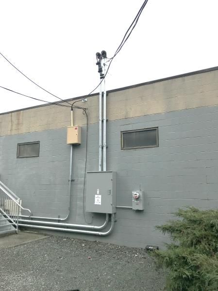
Requirements for Electric
                                   Service Connection

Welcome to the Seattle City Light Requirements for Electric Service Connection. This
handbook is designed for use by City Light customers, contractors, and electricians to
explain utility requirements for a variety of electric service installations.

Mike Haynes, Chief Operating Officer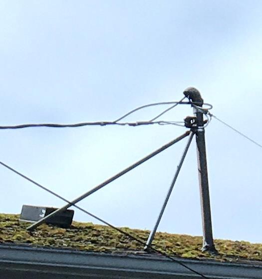
Seattle City Light
Requirements for Electric Service Connection
   Published by the Seattle City Light Standards Org
                 Seattle, Washington
              Rev. Date: November 2019

    Prepared by Dan Langdon and Laura Vanderpool

                 Acknowledgements:
                   Eivind Perander
                       Alan Hall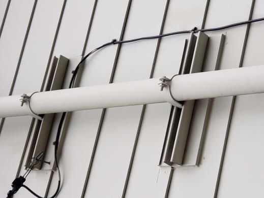
Table of Contents
1.   Getting Started: Applying for Electric Service ..........................................................................1
     1.1.   Introduction ....................................................................................................................................................... 1
     1.3.   Connection Timeline ...................................................................................................................................... 1
     1.4.   Service Connection ......................................................................................................................................... 2
     1.5.   Charges ............................................................................................................................................................... 2
     1.6.   Application Process for New or Enlarged Services ............................................................................ 2
                    1.6.1.        Pre-Application Consultation ........................................................................................................................ 2
                    1.6.2.        Application for Electric Service ..................................................................................................................... 2
     1.7.          Permitting and Inspections ......................................................................................................................... 3
     1.8.          Easements .......................................................................................................................................................... 3
     1.9.          Location of, and Excavation Near, Underground Utilities ............................................................... 4
     1.10.         Clearances .......................................................................................................................................................... 4
     1.11.         Notification of Added Load......................................................................................................................... 5
     1.12.         Balanced Load .................................................................................................................................................. 5
     1.13.         Available Fault Current .................................................................................................................................. 6
     1.14.         Online Resources ............................................................................................................................................. 6
     1.15.         Installation of Facilities for Other Utilities ............................................................................................. 6
2.   Temporary Services .....................................................................................................................7
     2.1. Introduction ....................................................................................................................................................... 7
     2.2. Requirements, General .................................................................................................................................. 7
     2.3. Time Limit ........................................................................................................................................................... 7
     2.4. Electrical Permits and Inspections ............................................................................................................ 7
     2.5. Charges ............................................................................................................................................................... 7
     2.6. Engineering Requirements for Large Services ..................................................................................... 7
     2.7. Temporary Overhead Service ..................................................................................................................... 7
     2.8. Temporary Underground Service ............................................................................................................. 9
3.   Looped Radial Service.............................................................................................................. 10
     3.1.  Introduction .................................................................................................................................................... 10
     3.2.  Single Service Rule ....................................................................................................................................... 10
     3.3.  Available Service Voltages and Maximum Secondary Service Entrance Ratings ................ 10
     3.4.  Clearances ....................................................................................................................................................... 11
     3.5.  Water Entry Prevention .............................................................................................................................. 11
     3.6.  Secondary Service ........................................................................................................................................ 11
                    3.6.1.        Secondary Overhead Services .................................................................................................................... 12
                    3.6.2.        Secondary Underground Services ............................................................................................................ 18
     3.7.          Primary Service .............................................................................................................................................. 19
                    3.7.1.        Water Entry Prevention ................................................................................................................................. 20
                    3.7.2.        Vault Access ....................................................................................................................................................... 21
     3.8.          Fire Clearance ................................................................................................................................................ 21
     3.9.          Vibration and Noise Levels ....................................................................................................................... 22
     3.10.         Elevators ........................................................................................................................................................... 22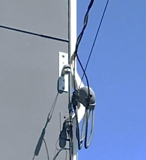
3.11.         Special Services ............................................................................................................................................. 22
                   3.11.1.        Mobile Home Parks ........................................................................................................................................ 22
                   3.11.2.        Mobile Homes on Individual Owner Lots (not part of a mobile home community) .......... 22
                   3.11.3.        Houseboat Piers ............................................................................................................................................... 22
                   3.11.4.        Boat Moorages ................................................................................................................................................. 22
                   3.11.5.        Unit Lot Subdivisions ..................................................................................................................................... 22
4.   Network Services ..................................................................................................................... 23
     4.1.  Introduction .................................................................................................................................................... 23
     4.2.  Single Service Rule ....................................................................................................................................... 23
     4.3.  Clearances ....................................................................................................................................................... 23
     4.4.  Permitting and Inspections ...................................................................................................................... 23
     4.5.  Service Notes, General ............................................................................................................................... 23
     4.6.  Vault Construction ....................................................................................................................................... 24
     4.7.  Water Entry Prevention .............................................................................................................................. 25
     4.8.  Vault Access.................................................................................................................................................... 25
     4.9.  Fire Clearance ................................................................................................................................................ 25
     4.10. Vibration and Noise Levels ....................................................................................................................... 26
     4.11. Elevators ........................................................................................................................................................... 26
     4.12. NEC-Sized Service Entrances in Network Areas ............................................................................... 26
     4.13. Secondary Service ........................................................................................................................................ 26
     4.14. Primary Service .............................................................................................................................................. 27
     4.15. Fault Current Limiters ................................................................................................................................. 27
5.   Customer Generation ............................................................................................................... 29
     5.1.  Net Metering .................................................................................................................................................. 29
     5.2.  Customer Generation Within the City Light Network Service Areas ....................................... 30
     5.3.  Production Metering ................................................................................................................................... 30
6.   Metering ................................................................................................................................... 32
     6.1.   Introduction .................................................................................................................................................... 32
     6.2.   Requirements, General ............................................................................................................................... 32
                   6.2.1.         Service Entrance Conductors for Metered Loads .............................................................................. 32
                   6.2.2.         Conductor Connections ................................................................................................................................ 32
     6.3.          Voltages ........................................................................................................................................................... 33
     6.4.          Meter Sockets ................................................................................................................................................ 33
     6.5.          Location, Access, and Protection of Metering Equipment ........................................................... 34
                   6.5.1.         Location ............................................................................................................................................................... 34
                   6.5.2.         Access to Metering Equipment ................................................................................................................. 35
                   6.5.3.         Protection ........................................................................................................................................................... 35
     6.6.          Meter Height and Clearances .................................................................................................................. 36
                   6.6.1.         Meter Height ..................................................................................................................................................... 36
                   6.6.2.         Clearances .......................................................................................................................................................... 36
     6.7.          Service Entrance Equipment Sequencing ........................................................................................... 37
     6.8.          Special Metering Requirements for Multi-Unit Buildings ............................................................ 38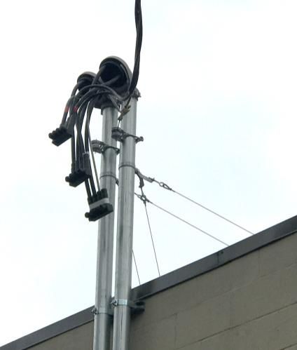
6.9.          Current Transformers .................................................................................................................................. 39
                   6.9.1.         Current Transformer-Rated Metering..................................................................................................... 39
                   6.9.2.         Landing Pads and Enclosures ..................................................................................................................... 40
                   6.9.3.         Secondary Wiring ............................................................................................................................................ 41
     6.10.         Switchgear ....................................................................................................................................................... 42
                   6.10.1.        General................................................................................................................................................................. 42
                   6.10.2.        Switchgear Operating at Voltages Up to and Including 480V ..................................................... 42
                   6.10.3.        Switchgear Operating at Voltages Greater Than 480 V .................................................................. 42
     6.11.         Master Metering ........................................................................................................................................... 43
     6.12.         Advanced Metering Infrastructure (AMI) for Meter Rooms ........................................................ 43
     6.13.         Totalized Metering ....................................................................................................................................... 44
     6.15.         Net Metering .................................................................................................................................................. 45
7.   Motors and Special Loads ....................................................................................................... 46
     7.1.  Introduction .................................................................................................................................................... 46
     7.2.  Motor-Starting Limits and Interference .............................................................................................. 46
     7.3.  Voltage Flicker ............................................................................................................................................... 46
     7.4.  Starting Limitations on Single-Phase Motors ................................................................................... 46
     7.5.  Starting Limitations on Polyphase Motors for Secondary Services.......................................... 47
     7.6.  Electric Power Regeneration Due to Motor Drive/Control .......................................................... 47
     7.7.  Maximum Switched Load .......................................................................................................................... 47
     7.8.  Welding Equipment..................................................................................................................................... 48
     7.9.  Minimum Power-Factor Limitations ..................................................................................................... 48
                   7.9.1.         Lighting................................................................................................................................................................ 48
                   7.9.2.         85% Minimum Power Factor ...................................................................................................................... 48
                   7.9.3.         Capacitor Control ............................................................................................................................................ 48
8.   Protective Devices and Back-Up Generators ......................................................................... 49
     8.1.   Inverter-Based Generator Systems ........................................................................................................ 49
     8.2.   Transfer Switches .......................................................................................................................................... 49
                   8.2.1.         Approval .............................................................................................................................................................. 49
                   8.2.2.         Means of Disconnection............................................................................................................................... 49
                   8.2.3.         Frequency ........................................................................................................................................................... 50
                   8.2.4.         Waveform ........................................................................................................................................................... 50
                   8.2.5.         Voltage Magnitude ......................................................................................................................................... 50
     8.3.          Phase Sequence ............................................................................................................................................ 50
     8.4.          Phase Voltage ................................................................................................................................................ 50
     8.5.          Equipment ....................................................................................................................................................... 50
     8.6.          Protective Equipment ................................................................................................................................. 50
     8.7.          Protective Relays........................................................................................................................................... 51
     8.8.          Lockout Relays ............................................................................................................................................... 51
     8.9.          Voltage Relays ............................................................................................................................................... 51
     8.10.         Synchronization of Equipment ................................................................................................................ 51
     8.11.         Locks on Disconnect Switches ................................................................................................................ 52
9. Technical Requirements .......................................................................................................... 53
9.1. Electromagnetic Interference .................................................................................................................. 53
9.2. Power Surges, Faults, Transients, and Outages ................................................................................ 53
10. Maintenance of Equipment and Facilities .............................................................................. 54
10.1. Introduction .................................................................................................................................................... 54
10.2. Charges ............................................................................................................................................................ 55
10.3. Temporary Restoration of Service ......................................................................................................... 55
Glossary ............................................................................................................................................... 56
Appendix: Multi-Unit Metering Pre-Job Checklist .......................................................................... 621. Getting Started: Applying for Electric Service
1.1. Introduction
This chapter outlines the process for applying for service and securing all permits and inspections, as well
as provides a timeline of average turnaround times to complete the application process.
A collection of construction and material standards related to electric service can be found at
http://www.seattle.gov/light/engineerstd/ElectricalSvc.aspx.
1.2. Service Areas
A map of the City Light service area can be found at seattle.gov/light/electricservice/map.asp. Customers
will be assigned a City Light Representative based on the location and complexity of the project.
City Light has two categories of distribution: Looped Radial and Network. Network areas include
Downtown Seattle, South Lake Union, First Hill, and parts of the University District. Requirements related
to the Looped Radial system are discussed in Chapter 3, and requirements related to our Network areas
are discussed in Chapter 4.
1.3. Connection Timeline
Table 1.3 shows estimated times required for each phase of the application process. Projects requiring
special transformation or line extensions depend in part on equipment availability.
TABLE 1.3. ESTIMATED TURNAROUND TIMES PER PHASE OF APPLICATION PROCESS, LOOPED
RADIAL
Application Service
Service Type Processing Engineering Connections
Service removal – simple (single-phase, 400 A or less) 1 week Not applicable 2 weeks
Service removal – complex (three-phase and/or underground) 1 week 4 weeks 2 weeks
Temporary power – simple (single-phase, overhead, 400 A or less) 1 week Not applicable 2 weeks
Temporary power – complex (three-phase and/or underground) 1 week 4 weeks 2 weeks
Service upgrade – simple (single-phase, overhead, 200 A or less) 1 week 2 weeks 2 weeks
Service upgrade – complex (three-phase and/or underground) 1 week 6 weeks 2 weeks
New service - simple (single-phase, overhead, 400 A or less) 1 week 4 weeks 2 weeks
New service – complex (three-phase and/or underground) 1 week 6-8 weeks 4 weeks*
Line extensions, plat development 1 week 8-10 weeks 8 weeks*
* Add up to five weeks for non-arterial street permitting, and fifteen weeks for arterial permitting.
Notes:
1. Network projects have unique timelines. For more information, consult your City Light Representative.
2. It is essential that contractors notify City Light well in advance of designing their buildings, as the requirements for a
primary service may alter the building design. For instance, City Light may require space not only for the vault, but
for a primary switchgear room as well.
CITY LIGHT REQUIREMENTS FOR ELECTRIC SERVICE CONNECTION REV. DATE NOVEMBER 2019 | PAGE 11.4. Service Connection
City Light will make service connections only when:
• All applicable City Light requirements have been met
• The customer’s responsibilities, as delineated herein, in a service construction letter, in a
contract, or via an in-field conversation with a City Light Representative have been fulfilled.
• All City Light inspections have been completed and the project approved.
1.5. Charges
City Light will determine charges for service work based on the size of the service, the service location,
and the work required to connect it to our system. Charges must be paid prior to the work being done.
See City Light Departmental Policy and Procedure (DPP) 417 for current connection charges.
1.6. Application Process for New or Enlarged Services
1.6.1. Pre-Application Consultation
City Light provides general engineering and service advice prior to application to determine project
feasibility and considerations.
Contact information:
Small/Medium Projects
(206) 233-APPS (2777)
Email: SCL_serviceapplications@seattle.gov
Large Commercial and Industrial Projects
(1 MW demand and greater)
Seattle Municipal Tower
700 5th Avenue
(206) 684-3186
Email: SCL_serviceapplications@seattle.gov
1.6.2. Application for Electric Service
Customers can apply for electric service using the online Application for Electric Service located at
www.seattle.gov/light/newconstruction/
Based on the application’s criteria, customers will need to submit a plan package for City Light review and
comment.
CITY LIGHT REQUIREMENTS FOR ELECTRIC SERVICE CONNECTION REV. DATE NOVEMBER 2019 | PAGE 2A typical plan package consists of the following elements:
• Legal Site Plan
• Electrical Site Plan
• Building Elevation Plan
• Riser Diagram
• Load Calculations
Additional documents, such as easements, in-building vault details, street improvement plans and short
plat/unit lot subdivision information may be required to complete the project. The City Light
Representative assigned to your project will advise customers of any additional documents required.
1.7. Permitting and Inspections
For projects located in the public right-of-way in incorporated King County, which includes Burien,
Lake Forest Park, Normandy Park Renton, SeaTac, Seattle, Shoreline, and Tukwila, customers can do all
civil construction work. The customer is responsible for securing all required permits and inspections.
For projects located in the public right-of-way in unincorporated King County, which includes
Skyway and White Center, City Light is required to do all civil construction work. City Light will acquire the
civil construction permits, perform the work, and bill the customer for all related costs including labor,
materials, permits, and inspections.
Customers will be responsible for acquiring all local jurisdictional permits and pass required inspections
and for verifying permit requirements with their local jurisdiction. The customer must pay all permit and
inspection fees. City Light will not connect to the customer’s service conductors until the proper code
authority has inspected and approved the service for connection.
Note: Electrical permits can only be obtained by customers if they are doing the work themselves.
If the work is being performed by an electrician, the electrician is required to obtain the permit.
Projects requiring engineering services will receive a Service Construction Letter. This letter will contain
customer drawings and references to all applicable City Light standards for the project, as well as
instructions for arranging City Light inspections.
The requirements stated in the Service Construction Letter will be part of the City Light inspection criteria.
The customer is also required to meet all applicable building codes for the city and county jurisdictions in
the City Light service area.
1.8. Easements
City Light will secure an easement whenever City Light equipment such as poles, vaults, handholes,
conductors, etc. are located on private property in order to serve multiple properties.
CITY LIGHT REQUIREMENTS FOR ELECTRIC SERVICE CONNECTION REV. DATE NOVEMBER 2019 | PAGE 31.9. Location of, and Excavation Near, Underground Utilities
Before digging, please contact the Utilities Underground Location Center (“One- Call”) at 811 or
1-800-424-5555 at least two business days in advance to locate and mark underground utilities, per state
law (RCW 19.122).
All excavations adjacent to City Light poles or other facilities (vaults, handholes, etc.) must comply with
WAC 296-155, Part N, Excavation, Trenching and Shoring. Pole protection/supporting systems used while
excavating must comply with WAC 296-155-655, General Protection Requirements, item (9) and must not
affect the structural integrity of poles while the systems are in place or after the systems have been
removed.
1.10. Clearances
The City Light minimum clearance from the edge of a crossarm to a building is 14 ft. The 14-ft clearance
allows for the following:
• Maintenance work environment is safer.
• Building work can occur without taking a clearance outage.
• Qualified electrical workers are not required to perform routine building maintenance.
• Scaffolding can be erected, and other exterior maintenance can occur while meeting the 10-ft
rule set by OSHA and WAC.
See Figure 1.10 for clarification.
CITY LIGHT REQUIREMENTS FOR ELECTRIC SERVICE CONNECTION REV. DATE NOVEMBER 2019 | PAGE 4Figure 1.10. Clearances
City Light transmission lines require even greater clearance. If a project requires work in proximity to any
energized lines, we may de-energize and ground the lines, or relocate the lines temporarily. This work will
be done at the customer's expense.
See City Light Construction Standard D2-3, “Clearances from Structures and Ground” for more
information on overhead clearances and City Light Construction Standard 0214.00, “Clearances Between
SCL Underground Structures and Other Structures” for more information on underground clearances.
1.11. Notification of Added Load
Customers who wish to add load to existing service must notify City Light per SMC 21.49 (S) and WAC
480.100.148 (1).
1.12. Balanced Load
The customer’s three-phase electrical load must be balanced between phases to a level acceptable to City
Light. For open-delta services, the customer is required to connect all single-phase loads across the
grounded phase.
CITY LIGHT REQUIREMENTS FOR ELECTRIC SERVICE CONNECTION REV. DATE NOVEMBER 2019 | PAGE 51.13. Available Fault Current
City Light will provide customer with available fault current upon request. It is the customer’s
responsibility to provide service entrance equipment designed to handle the available fault current.
1.14. Online Resources
The following City of Seattle resources may be viewed on the Internet:
• City Light New Construction Website
• City Light Construction and Material Standards Online
1.15. Installation of Facilities for Other Utilities
The specifications referenced in this manual do not include facilities for other utilities serving this project.
CITY LIGHT REQUIREMENTS FOR ELECTRIC SERVICE CONNECTION REV. DATE NOVEMBER 2019 | PAGE 62. Temporary Services
2.1. Introduction
This chapter provides information on all considerations related to obtaining temporary services, including
time limits, permitting and inspections, charges, required equipment, location of service connection, and
requirements specific to overhead and underground service.
2.2. Requirements, General
Temporary service locations must be approved by City Light.
The customer must provide temporary service entrance equipment.
2.3. Time Limit
Temporary service installations are limited to a period of one year. An extension may be granted at City
Light’s discretion.
2.4. Electrical Permits and Inspections
See Section 1.7.
2.5. Charges
See Section 1.5.
2.6. Engineering Requirements for Large Services
Three-phase temporary services and single-phase services greater than 400 A may require City Light
engineering design services.
2.7. Temporary Overhead Service
The service attachment must be able to withstand the strain of the service drop. Specifications for
temporary posts are shown in Figure 2.7.
The neutral wire must be identified with white tape.
For three-phase, open-delta service, the high leg must be identified with orange tape.
A total of 18 inches of conductor must extend out of the weatherhead.
CITY LIGHT REQUIREMENTS FOR ELECTRIC SERVICE CONNECTION REV. DATE NOVEMBER 2019 | PAGE 7Figure 2.7. Typical Overhead Temporary Service Pole
CITY LIGHT REQUIREMENTS FOR ELECTRIC SERVICE CONNECTION REV. DATE NOVEMBER 2019 | PAGE 82.8. Temporary Underground Service
Customer must install a conduit riser at the temporary panel location and trench to the City
Light-designated service stub, handhole, vault, or service pole. Figure 2.8 shows the basic pole and trench
specifications.
Figure 2.8. Typical Underground Temporary Service Pole
For more information on underground service on private property, See City Light Construction Standard
0224.01, “Customer Requirements for Underground Secondary Service, Looped Radial System” and City
Light Construction Standard 0224.07, “Requirements for Secondary Conduit Installation”
CITY LIGHT REQUIREMENTS FOR ELECTRIC SERVICE CONNECTION REV. DATE NOVEMBER 2019 | PAGE 93. Looped Radial Service
3.1. Introduction
“Looped Radial” refers to the City Light distribution system that comprises the entire service territory
outside of the Network areas. It has underground service and underground areas (such as business
districts and certain residential areas), but the primary source of wires that feed these customers are from
overhead distribution poles.
3.2. Single Service Rule
This rule states that City Light will provide only one service to a site or building. Additional services will be
supplied only at City Light’s option and will be agreed to in writing. If City Light needs to add equipment
to the distribution system to provide a second service, the customer will be billed the full cost of that
addition, including the equipment.
3.3. Available Service Voltages and Maximum Secondary Service Entrance Ratings
Table 3.3 shows the available service voltages and corresponding maximum secondary service entrance
ratings for service in the Looped Radial system
TABLE 3.3. AVAILABLE SERVICE VOLTAGES AND MAXIMUM SECONDARY SERVICE
ENTRANCE RATINGS
Single-Phase Service Voltage (V) Service Maximum Secondary Service Rating (A)b
120/240 Primary and Secondary 600
240/480 Primary and Secondary 300
Three-Phase Service Voltage (V)
120/208Y Primary and Secondary 1000
120/240 Open Deltaa Primary and Secondary 600
277/480Y Primary and Secondary 600
240/480 Open Deltaa Primary and Secondary 300
2400/4160Y Primary only Not applicable
7960/13,800Y Primary only Not applicable
15,420/26,400Y Primary only Not applicable
a The maximum allowable secondary service ampacities indicated in the table represent the total single-phase and
three-phase loads combined. The customer will be required to connect all single-phase loads across the grounded phase,
unless otherwise agreed to by City Light.
b Primary service does not have maximum service ratings.
If service ampacity exceeds 600 A, City Light may require an underground service. At City Light’s option, an exception to
the maximum service amperes may be granted for 120/208Y service in buildings that are exclusively for residential
occupancy. This exception will be in writing.
CITY LIGHT REQUIREMENTS FOR ELECTRIC SERVICE CONNECTION REV. DATE NOVEMBER 2019 | PAGE 10Single–phase, three‐wire and three‐phase, four‐wire service can be provided. Three‐phase, three‐wire
service is not available at any voltages.
The service rating must be determined by the nameplate ampere rating of the main service disconnect. In
the absence of a single main service disconnect, City Light will determine the service rating by the
nameplate rating of the main service bus or the rating of the main busing in the service entrance panel,
whichever applies.
In buildings where multiple services are connected from one service drop or service lateral, the service
rating for the building will be the aggregate of the individual service ratings.
Services to larger buildings, commercial office buildings and apartment buildings may have large electrical
services where the aggregate service entrance capacity exceeds the allowed maximum secondary service
size listed in Table 3.3. For these services, the customer must provide a vault or pad on private property
for City Light transformer(s) and associated service equipment. See Section 3.7, Primary Service.
Transformers connected to the City Light distribution system will be furnished, installed and maintained
by City Light.
If the customer requires a voltage other than the stated standard voltages, the customer must supply the
equipment required. All special transformation equipment must be installed on the load side of the meter,
unless otherwise agreed to in writing.
Vaults, pads and termination facilities must be furnished by the customer in accordance with City Light
standards and other codes pertaining to the corresponding Authority Having Jurisdiction.
3.4. Clearances
All projects must meet the requirements for clearances from utility equipment. See Section 1.10.
3.5. Water Entry Prevention
The customer is responsible for the following measures to avoid water entry into buildings and service
equipment:
• System design that considers elevation differences and other factors that would cause a
problem. The design should prevent water from entering the building or electrical equipment
to prevent electrical hazard or property damage. A City Light Representative can advise the
customer in this concern.
• Watertight grouting of conduit where it enters the building, the vault, or the handhole.
• Watertight conduit sealing for customer/contractor installed conductors to prevent water
from entering the service conduits.
3.6. Secondary Service
“Secondary service” is defined as service that can be served from a transformer located in the public
right-of-way on a pole, on a pad, or in a vault.
CITY LIGHT REQUIREMENTS FOR ELECTRIC SERVICE CONNECTION REV. DATE NOVEMBER 2019 | PAGE 11Secondary service can be either overhead or underground, single-phase or three-phase.
Most single-family residential service in the City Light system is single-phase; however, there are instances
where three-phase service is available.
Some local jurisdictions regulate the type of services allowed within their boundaries (overhead vs.
underground). The customer must contact the Authority Having Jurisdiction to verify allowable types of
service.
3.6.1. Secondary Overhead Services
Types of secondary overhead service include service mast with and without supporting wires, and
wall-mounted.
Neutral must be identified with white tape, high leg identified with orange tape, and three-phase circuits
identified appropriately.
The distance between weatherheads served from the same service drop must not exceed 24 inches.
Service entrance conductor sets must have a minimum of 18 inches of wire extending from the
weatherhead. If multiple service masts are installed, a minimum of 30 inches of wire must be extended
from the weatherhead.
Customer must establish a 3-ft radius of clear space along the path between the utility pole and the strike
point on the building.
Service conductors must be free of trespass of neighboring properties.
The point of attachment must be between 12 and 20 ft above grade, with the drip loop a minimum of
11 ft above grade.
Figure 3.6.1. Vertical Clearances in the Spans
CITY LIGHT REQUIREMENTS FOR ELECTRIC SERVICE CONNECTION REV. DATE NOVEMBER 2019 | PAGE 12For more information on service drops, see City Light Construction Standard 0130.30, “Secondary Service
Drops”
3.6.1.1 Service Mast Installation
Service mast installation for overhead service entrances may be surface-mounted or flush-mounted.
The customer must provide all the equipment shown in figures 3.6.1.1a and 3.6.1.1b except the City
Light-provided meter, which plugs into the customer’s meter socket.
Flush mounted meter sockets require a cover inspection by a City Light Representative. See Figure
3.6.1.1b.
A back guy or a stiff-leg set is required if the height between the top of the weatherhead and where the
mast clears the roofline exceeds 26 inches or the service drop exceeds 100 ft. See figures 3.6.1.1c and
3.6.1.1d.
City Light-approved service brackets must be furnished and installed by the customer. Brackets and their
attachments need to be capable of withstanding the tension of the service wires. The point of attachment
must be between 12 and 20 ft above grade. See Figure 3.6.1.1e.
For service masts where the bracket is attached to the mast, rigid steel conduit with two points of
attachment are required. Single-phase services must have a minimum 2-inch conduit, three-phase
services must have a minimum 3-inch conduit. The service mast must be within 3 ft of the roof edge.
The service bracket must be a minimum of 18 inches above the roofline, and no closer than 8 inches from
the weatherhead.
Roof brackets are not allowed.
Service masts must be attached to the structure at two points at least 2 ft apart.
Attachment methods may include the following:
• Kindorf brackets on the exterior of the building.
• U-bolts into a 2 in x 6 in board mounted to studs.
See figures 3.6.1.1f and 3.6.1.1g.
Roof penetrations (e.g., eaves, fascia, etc.) must not be used as an attachment point.
CITY LIGHT REQUIREMENTS FOR ELECTRIC SERVICE CONNECTION REV. DATE NOVEMBER 2019 | PAGE 13Figure 3.6.1.1a. Surface-Mounted Service Mast Installation
CITY LIGHT REQUIREMENTS FOR ELECTRIC SERVICE CONNECTION REV. DATE NOVEMBER 2019 | PAGE 14Figure 3.6.1.1b. Flush-Mounted Service Mast Installation
CITY LIGHT REQUIREMENTS FOR ELECTRIC SERVICE CONNECTION REV. DATE NOVEMBER 2019 | PAGE 15Figure 3.6.1.1c. Back Guy Figure 3.6.1.1d. Stiff Leg Set
Figure 3.6.1.1.e. Service Bracket Figure 3.6.1.1f. Kindorf Bracket Attachment
3.6.1.2 Wall-Mounted Service Installation
All wall-mounted service brackets and Kindorf brackets must be secured by lag screws, 3/8 in x 4 in
minimum, into solid wood, or 3/8 in bolts through 2 in minimum solid wood.
The point of attachment must be between 12 and 20 ft above grade, with the drip loop a minimum of
11 ft above grade.
The distance from the service bracket to the weatherhead(s) must not exceed 24 inches. See Figure 3.6.1.2.
CITY LIGHT REQUIREMENTS FOR ELECTRIC SERVICE CONNECTION REV. DATE NOVEMBER 2019 | PAGE 16Figure 3.6.1.2. Wall-Mounted Service Installation
CITY LIGHT REQUIREMENTS FOR ELECTRIC SERVICE CONNECTION REV. DATE NOVEMBER 2019 | PAGE 173.6.1.3 Service Poles and Guys
Service poles are: (1) poles that serve only one customer, and (2) are located on the customer’s property.
City Light may require a service pole on the customer’s property where:
• The distance from the City Light distribution pole to the customer’s point of service
attachment is greater than 150 ft.
• A clear, direct route without trespass is not available for the service drop from the distribution
pole to the customer’s point of service attachment.
Note: City Light must have a 12 ft-wide access road to set a pole on private property. If this
space is not available, services will need to be located underground. See Section 3.6.2.
• The applicable code authority requires a service pole.
City Light will install guys on service poles as needed.
3.6.2. Secondary Underground Services
All equipment must be installed by the customer at the customer’s expense. City Light will provide a
drawing specifying the route of the conduit required for the installation.
All work associated with trenching, backfill, and restoration must be completed by, and at the expense of,
the customer. See Section 1.7.
City Light will install the service conductors from the designated point of termination on the customer’s
property to the City Light facility in the right‐of‐way or easement area.
It is the customer’s responsibility to ensure required clearances between City Light underground
structures and other utilities’ structures.
A City Light Electrical Reviewer or Underground Crew must supervise the final 5 ft of trenching to any
energized City Light vault or handhole.
Figure 3.6.2 provides a visual guide to all the City Light standards that govern the City Light underground
secondary service.
CITY LIGHT REQUIREMENTS FOR ELECTRIC SERVICE CONNECTION REV. DATE NOVEMBER 2019 | PAGE 18Figure 3.6.2. Guide to Underground Secondary Service Standards
For more information on installing secondary underground services, please see City Light Construction
Standard 0224.01, “Customer Requirements for Underground Secondary Service, Looped Radial System”
for and City Light Construction Standard 0214.00, “Clearances Between SCL Underground Structures and
Other Structures”
3.7. Primary Service
Primary service is any service that exceeds the maximum secondary service capacity shown in Table 3.3.
These services require transformers or primary metering enclosures to be located in vaults or on pads
located on customer’s property.
The customer is required to be aware of and satisfy all applicable building codes for the City of Seattle as
well as other cities and county jurisdictions in the City Light service area.
CITY LIGHT REQUIREMENTS FOR ELECTRIC SERVICE CONNECTION REV. DATE NOVEMBER 2019 | PAGE 19Table 3.7 shows the City Light construction standards corresponding to transformer location.
TABLE 3.7. CONSTRUCTION REQUIREMENTS BY TRANSFORMER LOCATION
Transformer Location City Light Standards
Vault inside building SCL 0751.00, “Customer Requirements, In-Building Transformer Vaults, Network
and Looped Radial Systems”
SCL 0751.60, “Concurrent Customer Requirements, In-Building Transformer Vaults”
Vault outside building SCL 0732.50, “Customer Requirements for Below-Grade Transformer Service Vaults,
Looped Radial System”
Concrete pad outside building SCL 0724.50; Customer Requirements for Padmount Transformer Services, Looped
Radial System”
Note: Dimensions of the transformer vault or pad are determined by City Light and are contingent on:
• The capacity of transformer(s) to be installed. Transformer size is determined by the customer’s total electrical
load and aggregate service entrance capacity.
• The type of devices used for secondary connection to the customer’s NEC-sized service entrance equipment.
• The working clearance needed around the equipment.
All vault and pad-mounted transformers must be located to provide safe access and code clearances from
fire escapes, combustible materials, and other hazards. Building owners must make provisions to prevent
unwanted debris from accumulating in and around vaults and pads.
The customer must contact City Light well in advance of building design to receive the necessary
requirements. These specifications will be provided by City Light in the Service Construction Letter after
reviewing the customer’s plans.
3.7.1. Water Entry Prevention
The customer is responsible for the following measures to avoid water entry into buildings and service
equipment:
• System design that considers elevation differences and other factors that would cause a
problem. The design should prevent water from entering the building or electrical equipment
to prevent electrical hazard or property damage. A City Light Representative can advise the
customer in this concern.
• Watertight grouting of conduit where it enters the building, the vault, or the handhole.
• Watertight conduit sealing for customer/contractor installed conductors to prevent water
from entering the service conduits.
CITY LIGHT REQUIREMENTS FOR ELECTRIC SERVICE CONNECTION REV. DATE NOVEMBER 2019 | PAGE 203.7.2. Vault Access
The customer must provide properly supported, unobstructed access from the right-of-way to the vault
for City Light equipment handling machinery to deliver all necessary equipment. In-building vaults must
not be located more than one floor below the building’s exterior finished grade and must have elevator
access.
For all properties with an in-building vault, and for properties where below grade vaults and transformer
pads are located such that the customer cannot meet the requirements spelled out above, a City Light
Equipment Transportation Agreement (ETA) must be signed by the property owner.
An ETA is a legal document in which the building owner(s) take sole responsibility for moving the
transformer(s) into and out of the vault, to a mutually agreed-upon location from which City Light is able
to deliver or pick up the transformer(s) using our normal transportation methods and equipment.
All ETAs will be recorded on the property title at the property owner’s expense, as all future owners are
obligated to the same terms and conditions of the agreement. Any damage occurring to the transformer
during transportation by the building owner(s) and any additional expense incurred because of said
damage must be paid by the building owner(s).
A copy of the ETA must be kept in the vault, permanently installed in a document enclosure on the vault
wall beneath the light switch. The customer must provide and install a weatherproof enclosure large
enough to hold a paper copy of the ETA.
For vault construction requirements, see:
City Light Construction Standard 0751.00, Construction Requirement, In-Building Transformer Vaults,
Network and Looped Radial Systems
City Light Construction Standard 0751.60, Concurrent Customer Requirements, In-Building Transformer
Vaults
3.8. Fire Clearance
All vault and pad-mounted transformers must be located to provide safe access and code clearances from
fire escapes, combustible materials, and other hazards. This is necessary to comply with the fire clearance
requirements of City Light and the appropriate City, County, or State inspecting authorities. Building
owners must make provisions to prevent unwanted debris from accumulating in and around vaults and
pads.
The customer must contact City Light well in advance of building design to receive the necessary
requirements. These specifications will be provided by City Light in the Service Construction Letter after
reviewing the customer’s plans.
CITY LIGHT REQUIREMENTS FOR ELECTRIC SERVICE CONNECTION REV. DATE NOVEMBER 2019 | PAGE 213.9. Vibration and Noise Levels
The customer is responsible for isolating the transformer vault or pad so that sound and vibration levels
satisfy the applicable laws and ordinances of the Washington Administrative Code (WAC), the City of
Seattle, or other applicable jurisdictions, including the customer’s own requirements. Further, it is the
customer’s responsibility to mitigate any magnetic field effects from any customer-owned sensitive
equipment.
3.10. Elevators
Elevator service must be provided to any building level where a transformer vault is located.
3.11. Special Services
3.11.1. Mobile Home Parks
City Light will supply one service to a mobile home park per Seattle Municipal Code 21.49.100, Paragraph
H, Section 2. Installation and maintenance beyond the service connection point will be the owner’s
responsibility. Meter locations must be accessible, and meters grouped. See Chapter 6, Metering, for more
information.
3.11.2. Mobile Homes on Individual Owner Lots (not part of a mobile home community)
Mobile home installations that are not part of a mobile home community will require a service pole and
meter socket that is not attached to the mobile home, per NEC requirements.
3.11.3. Houseboat Piers
City Light service houseboats must be terminated on shore. The termination equipment must also be
approved by City Light.
City Light will not upgrade existing overhead distribution on houseboat piers. If additional loads require
upgrading of houseboat pier electrical distribution, it is the customer’s responsibility to do so.
3.11.4. Boat Moorages
New or upgraded service to boat mooring establishments must be master metered per Seattle Municipal
Code 21.49.100, Paragraph H, Section 1. See Chapter 6, Metering for more information.
3.11.5. Unit Lot Subdivisions
For unit lot subdivisions, the parent parcel is considered one development site. Service entrance
conductors must be combined in such a way that all structures on the parent parcel can be served from
one service drop or service lateral directly from the City Light distribution system. The design of the
distribution system to serve the site shall be within the sole discretion of City Light. No bridled services
will be allowed.
CITY LIGHT REQUIREMENTS FOR ELECTRIC SERVICE CONNECTION REV. DATE NOVEMBER 2019 | PAGE 224. Network Services
4.1. Introduction
Network service areas are designed to provide redundancy and continuity of service in the case of
outages and include protective devices to prevent backfeed onto the grid. Because of this, there are
special rules for customer generation. Please see Chapter 5, “Customer Generation” for more information.
City Light has four network service areas: Downtown, First Hill, University District, and the South Lake
Union Area.
Secondary services in network areas are served from street networks, where the transformers and related
equipment are located in facilities in the right of way. Primary services are served from spot networks,
where the facilities are located on the property of the service.
This chapter includes general guidelines for service installations in network areas. Customers must
contact City Light well in advance of the project starting to receive the required design specifications.
4.2. Single Service Rule
This rule states that City Light will provide only one service to a site or building. Additional services will be
supplied only at City Light’s option and will be agreed to in writing. If City Light needs to add equipment
to the distribution system to provide a second service, the customer will be billed the full cost of that
addition, including the equipment.
4.3. Clearances
All projects must meet the requirements for clearances from utility equipment. See Section 1.10.
4.4. Permitting and Inspections
See Section 1.7.
4.5. Service Notes, General
All services in the Network system are underground.
Single–phase, three‐wire and three‐phase, four‐wire service can be provided. Three‐phase, three‐wire
service is not available at any voltages.
The service rating must be determined by the nameplate ampere rating of the main service disconnect. In
the absence of a single main service disconnect, City Light will determine the service rating by the
nameplate rating of the main service bus or the rating of the main busing in the service entrance panel,
whichever applies.
In buildings where multiple services are connected from one service drop or service lateral, the service
rating for the building must be the aggregate of the individual service ratings.
CITY LIGHT REQUIREMENTS FOR ELECTRIC SERVICE CONNECTION REV. DATE NOVEMBER 2019 | PAGE 23You can also read