PCI Reconnaissance Team Report
←
→
Page content transcription
If your browser does not render page correctly, please read the page content below
P h o t o : J o s e p h R . Ma f f e i

                                                                          PCI Reconnaissance Team Report

            Observations
            from the February 27, 2010,
            earthquake in Chile

            S. K. Ghosh and Ned Cleland

                                                                                                                                he earthquake that shook Chile at 3:34 a.m. on
                                                                                                                                Saturday, February 27, 2010, was one of the
                                                                                                                                most devastating in the history of the country,
                                                                                                                                which has a 2650 mi (4270 km) coastline along
                                                                                                                    the Pacific Ring of Fire. The moment magnitude issued by
                                                                                                                    the U.S. Geological Survey1 was 8.8. The earthquake was
                                                                                                                    followed by hundreds of aftershocks, the strongest
                                              ■ The authors were part of a PCI reconnaissance team of inves-        measuring from 6.0 to 6.9 on the moment magnitude scale.
                                                tigators who went to various locations affected by the February     Table 1 gives the details of the earthquake.1
                                                2010 earthquake in Chile.
                                                                                                                    Maximum ground acceleration of up to 0.65g was recorded
                                              ■ The 1996 Chilean seismic code was similar to the then-current       at Concepción, and more than 6.6 ft (2 m) of uplift was
                                                UBC and ACI 318 codes, except that boundary elements and            observed near Arauco on the coast.1
                                                special transverse reinforcement were not required in structural
                                                walls. This exception was revoked in the 2009 version of the        The earthquake was generated at the gently sloping fault
                                                Chilean code due to a trend towards thinner walls.                  along which the Nazca plate moves eastward and downward
                                                                                                                    beneath the South American plate (Fig. 1). The two plates
                                              ■ The number of deaths and the amount of property loss were           are converging at 2¾ in. (70 mm) per year. The fault rupture,
                                                not disproportionate to the severity of the earthquake. Much of     largely offshore, exceeded 60 mi (100 km) in width and
                                                this is attributable to Chile’s history of adoption and implemen-   extended nearly 300 mi (500 km) parallel to the coast.
                                                tation of adequate building codes.
                                                                                                                    A comprehensive written record beginning in the mid-16th
                                              ■ The 2010 emergency changes to the Chilean Building Code             century describes large damaging earthquakes throughout
                                                have far-reaching implications for the special structural wall      the region that was affected by the February 27, 2010,
                                                design provisions in ACI 318.                                       earthquake. An 1835 M8.2 (M = moment magnitude)

52                                                                W int e r 2 0 1 2 | PCI Journal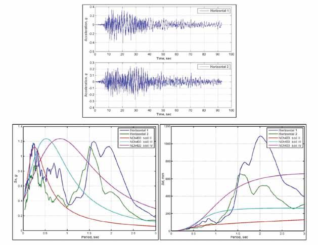
Table 1. Earthquake details
 Concepción earthquake is notable because famed naturalist
                                                                                    Moment magnitude           8.8
 Charles Darwin and naval officer Robert FitzRoy provided
 observations and comments.1 Since the beginning of the                                                        Saturday, February 27, 2010,
                                                                                    Date-time
 20th century, there have been M8.2 earthquakes in 1906,                                                       at 03:34:14 a.m. at epicenter
 1943, and 1960, and an M8.0 earthquake in 1985.1 The
 1960 M8.2 earthquake was a foreshock that occurred a day                           Location                   35.909°S, 72.733°W
 before the great M9.5 Chilean earthquake of 1960.1                                 Depth                      21.7 mi

 The 2010 earthquake that is the subject of this paper struck                       Region                     Offshore Maule, Chile
 in an area previously identified as a seismic gap extending                                                   60 mi NW of Chillán, Chile
 from Constitución in the north to Concepción in the south
 with a projected worst-case potential to produce an earth-                                                    65 mi NNE of Concepción, Chile
 quake with M between 8.0 and 8.5.2 The rupture extended                            Distances
 beyond the northern and southern boundaries of the gap,                                                       70 mi WSW of Talca, Chile
 overlapping extensive zones already ruptured in 1985 and
 1960.3                                                                                                        210 mi SW of Santiago, Chile

 Strong-motion records                                                              Source: U.S. Geological Survey. Note: 1 mi = 1.61 km.

 The University of Chile’s strong-motion instrumenta-
 tion array recorded motions at several sites in the heav-                          ment response spectra for the same ground motions. The
 ily stricken region. Some of the digital data have been                            acceleration spectra show unusual second peaks at periods
 processed and reported by the University of Chile4 and by                          of 1.5 sec and longer. The acceleration and displacement
 Boroschek et al.5 Figure 2 shows three sets of recorded ac-                        spectra are compared with the design spectra for soil types
 celerograms and the corresponding response spectra from                            II, III, and IV as defined in NCh433-2009.
 the Santiago area. Ground accelerations exceeding 0.05g
 lasted more than 60 sec according to most of the records.                          Figure 4 shows horizontal ground motion accelerograms
 Elastic response spectra of several records are higher than                        from Colegio San Pedro, across the Bio Bio River south-
 the elastic design spectrum of the Chilean seismic code,                           west of downtown Concepción, along with their accelera-
 NCh433-2009.6                                                                      tion and displacement response spectra. The acceleration
                                                                                    spectra show second peaks at periods of about 0.8 sec.
 Figure 3 shows horizontal ground motion accelerograms                              Again, the design spectra for soil types II, III, and IV are
 from downtown Concepción. A special characteristic of                              also shown.
 the records is the long duration of strong shaking (90 sec
 or more). Also shown are the acceleration and displace-

Figure 1. The source of the Chile earthquake is at the convergence of the Nazca and the South American plates. Source: Roberto Leon presentation at www.eqclear
inghouse.org/20100227-chile/wp-content/uploads/2010/04/Leon-Chile-Earthquake.pdf. Note: 1 mi = 1.61 km.

                                                                                                            PCI Journal | Wi n t e r 2012                         53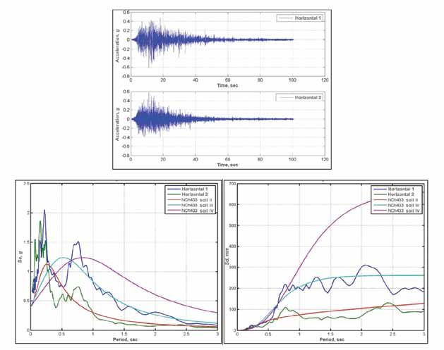
Figure 2. Accelerograms and corresponding acceleration response spectra (β = 5%) from the Santiago, Chile, area. Source: Boroschek et al. 2010. Note: g = accel-
     eration due to earth’s gravity; EW = east-west; NS = north-south; Sa = spectral acceleration; T = time; UD = up-down; β = damping coefficient.

     Figure 3. Accelerograms and corresponding acceleration and displacement response spectra (β = 5%) from downtown Concepción, Chile. Source: Boroschek et al.
     2010. Notes: g = acceleration due to earth’s gravity; Sa = spectral acceleration; Sd = spectral displacement; β = damping coefficient. 1 cm = 0.4 in.

54                           W int e r 2 0 1 2 | PCI Journal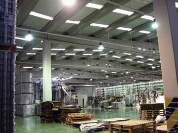
Figure 4. Accelerograms and corresponding acceleration and displacement response spectra (β = 5%) from Colegio San Pedro, Chile. Source: Boroschek et al. 2010.
Notes: g = acceleration due to earth’s gravity; Sa = spectral acceleration; Sd = spectral displacement; β = damping coefficient. 1 cm = 0.4 in.
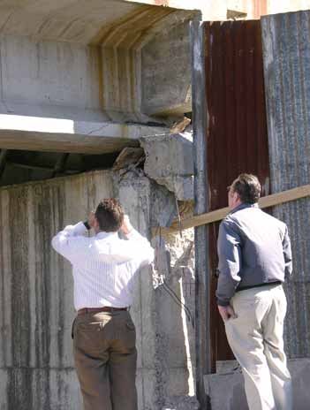
PCI investigation The Structural Engineering Institute of the American
Society of Civil Engineers (ASCE) sent an earthquake
The entire team visited Chile April 26–29, 2010, to inves- assessment team to assess the effectiveness of Chile’s
tigate damage in Santiago, Concepción, Talca, Chillán, building methods and codes, which closely parallel those
Coronel, and Chillán Viejo. Three team members spent an used in the United States. The primary purpose of the
additional day visiting Valparaiso/Viña del Mar. team was to determine whether changes are warranted to
the U.S. codes, standards, or practice in general and to
Other investigations ASCE 7-10 Minimum Design Loads for Buildings and
Other Structures8 and ASCE 41-06 Seismic Rehabilita-
A team organized by the Earthquake Engineering Re- tion of Existing Buildings9 in particular. Part of the team
search Institute (EERI) investigated the effects of the Chile traveled to different locations to study structures built after
earthquake. The team was assisted by local university the 1985 earthquake, when more-detailed building codes
faculty and students. Geotechnical Extreme Events Recon- were implemented. The remainder of the team focused on
naissance (GEER) contributed geosciences, geology, and structures such as steel mills and power plants.
geotechnical engineering findings. The Technical Council
on Lifeline Earthquake Engineering (TCLEE) contributed The report of the assessment team has not been published
a report based on its reconnaissance. Based on its own yet, so no definite conclusions are available. The team ob-
investigation and the GEER and TCLEE input, EERI pub- served several differences between the Chilean standards
lished the EERI Special Earthquake Report—June 2010 as and those in the United States. For example, the walls of
an insert in EERI’s monthly newsletter.3 EERI also set up a buildings are much thinner than is required in the United
Chile Earthquake Clearinghouse.7 States and do not contain as much reinforcement. Despite
its observations of significant nonstructural damage and
their review of plans, the team did not identify anything
PCI Journal | Wi n t e r 2012 55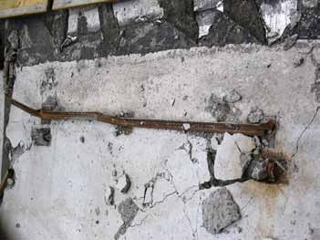
ment in walls of bearing-wall buildings may be necessary
                                                                      at the extremities of walls having T-shaped, L-shaped, or
                                                                      similar cross sections, but that confinement is typically not
                                                                      required for symmetrically reinforced, rectangular wall
                                                                      cross sections. Wallace and Moehle15 went on to state,
                                                                      “The good performance of the majority of these [bear-
                                                                      ing wall] buildings during the March 3, 1985, earthquake
                                                                      suggests that bearing walls with limited detailing may be
                                                                      an effective construction form for earthquake resistance.
                                                                      Although buildings in Chile are designed for roughly the
                                                                      same lateral forces as those in regions of high seismic risk
                                                                      in the United States, the typical structural wall in a Chilean
                                                                      building does not require boundary elements or special
                                                                      transverse reinforcement.”
     Figure 5. Damaged coupling beam in Viña del Mar, Chile.
                                                                      Based on this, NCh433-199611 contained clause B.2.2,
                                                                      which states, “When designing reinforced concrete walls,
      that would necessitate substantive changes to U.S. stan-        it is not necessary to meet the provisions of paragraphs
      dards such as ASCE 7-108 or ASCE 41-06.9                        21.6.6.1 through 21.6.6.4 of the ACI 318-9513 code.”
                                                                      These ACI 318-95 sections are for specially confined
      The Los Angeles Tall Buildings Structural Design Council        boundary elements at the edges of shear walls. NCh433-
      also sent a team. Its report is not yet available; however, a   20096 rescinded this exception before the February 2010
      presentation is posted on its website.10                        earthquake because of a trend to use thinner walls more in
                                                                      recent years than in the past.
      With so much information already available or coming
      soon, this report concentrates largely on the performance of    Tall concrete buildings are typically found in the metro-
      precast concrete structures, though some other aspects are      politan areas around Santiago, Valparaiso/Viña del Mar,
      also included.                                                  and Concepción. In Viña del Mar, a number of buildings
                                                                      that were damaged in the 1985 earthquake and repaired
      Building performance                                            suffered significant damage once again. However, damage
                                                                      was largely concentrated in newer buildings. The failure
      Mid- to high-rise buildings in Chile are predominantly of       of one tall building in Viña del Mar was due to the wide
      reinforced concrete construction. Most of these buildings use   spacing of transverse reinforcement in shear walls, which
      structural walls to resist both gravity loads and earthquake    caused the vertical bars to buckle, in this particular case,
      forces. Dual systems of walls and frames are occasionally       without fracture. In many other cases the vertical bars did
      used in newer construction. Typical wall cross-sectional        fracture.
      area–to–floor area ratios are high compared with values
      commonly used in U.S. concrete building construction.           Coupling beams over doorways typically have inadequate
                                                                      reinforcement. Many of these beams suffered damage
      In 1996, the Chilean seismic code (NCh433-1996)11 adopt-        (Fig. 5). Some buildings lacked coupling beams. In many
      ed analysis procedures similar to those in the 1997 Uniform     of those cases, damage resulted from the slab acting as
      Building Code (UBC).12 However, there are no prohibitions       the coupling element. There were several instances of
      or penalties related to vertical or horizontal system irregu-   doors that jammed because of displacements in the walls
      larities. NCh433-1996 also enforces provisions of Building      on either side. Spalled cover on top of lap splices of wall
      Code Requirements for Structural Concrete (ACI 318-95)          boundary reinforcement was a common occurrence.
      and Commentary (ACI 318R-95),13 with one significant
      exception, as noted in the following paragraph.                 Four mid- to high-rise concrete buildings collapsed com-
                                                                      pletely or partially. Two of these were nearly identical,
      Having observed and investigated the performance of             side-by-side, five-story buildings in Maipú, Santiago (not
      reinforced concrete buildings during the 1985 Chile earth-      visited by the PCI team). According to the EERI Special
      quake, Wood14 and Wallace and Moehle15 reached nearly           Earthquake Report,3 these buildings had four stories of
      identical conclusions. The primary variables that determine     condominium units atop a first-story parking level with an
      the need for confined boundary elements in shear walls          irregular wall layout. Wall failures apparently contributed
      were found to be the ratio of wall cross-sectional area to      to the collapses.
      floor-plan area, the wall aspect ratio and configuration, the
      axial load on the wall, and the reinforcement ratio of the      A third collapsed building was the 15-story Alto Río con-
      wall. Wallace and Moehle concluded that concrete confine-       dominium in Concepción (Fig. 6). The team was unable

56                           W int e r 2 0 1 2 | PCI Journal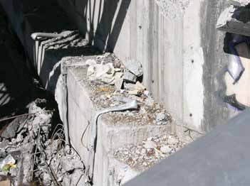
to examine closely the side of the building toward which it
collapsed. According to the EERI Special Earthquake Report,3
the structural drawings indicated that concrete walls on the
facade were discontinuous and that the wall lengths were
decreased in the first story on the side toward which the build-
ing collapsed. There was ample indication that the building
had rotated about its corridor walls as it collapsed, leading to
tension failures of the transverse walls on the side from which
the photo was taken. Some of the wall vertical reinforcement
fractured, and some lap splices failed on the tension side.

The fairly new 23-story O’Higgins office building in Con-
cepción suffered partial story collapses at levels 10, 14, and
18, each coincident with a framing setback (Fig. 7). The
perforated shear walls on the east face (shown) and south
                                                                   Figure 6. The 15-story Alto Río Condominium in Concepción, Chile.
face showed damage to both wall piers and spandrels. The
exterior north and west faces appeared undamaged.
                                                                          crushing and buckling or fracture of reinforcement
The following observations of building performance                        across entire wall (unzipping) should be investigated.”
emerged:
                                                                    Precast concrete buildings
•   Axial stress in shear walls. As mentioned previously,
    Chilean buildings typically contain many shear walls.           The precast concrete construction market in Chile does not
    This contributed to their relatively good performance           include parking structures but does include bridges, office
    during the 1985 earthquake. Newer buildings appear to           buildings, stadiums, warehouses, and industrial buildings.
    have the same shear wall area in terms of the percent-          Some systems did not fare well during the February 27,
    age of floor area, but many are significantly taller than       2010, earthquake. Many buildings of more recent construc-
    before. This suggests that the axial stress in the walls        tion did well, and some advanced precast concrete con-
    of newer buildings is significantly higher than in older        cepts proved their merit.
    buildings. This may, at least in part, be responsible for
    the widely observed localized wall damage character-            Gable frames
    ized by buckling of vertical reinforcement.
                                                                    One precast concrete system that did not perform well was
•   Confinement of wall boundary elements. The                      a precast concrete gable frame system at Parque Industrial
    exception made in NCh433-19966 to the specially                 Escuadrón. The roof of the single-story San José Fishery
    confined boundary zone requirements of ACI 318-9513             was formed by a series of these frames. The structure was
    was explained previously. Considerable damage was               reported to be 23 years old but appeared older. Figure 8
    observed in many wall boundary elements, including              shows the portion of the building still standing after the
    crushing of concrete and buckling and fracture of lon-          earthquake.
    gitudinal reinforcement. The exception was rescinded
    in NCh433-2009. However, the ACI 318-0816 require-
    ments have now come into question. The trigger for
    requiring specially confined boundary zones should be
    reexamined. The reduction of the boundary element
    confinement requirements when specially confined
    boundary zones are not triggered should also be
    reviewed.

•   Vertical wall reinforcement. This item has been
    described by Wallace:17 “Many damaged walls were
    lightly reinforced and had unconfined lap splices.
    These walls were observed to have problems at lap
    splices or to suffer tension failures (or fractures during
    buckling following tensile elongation). Due to the long
    duration of the earthquake, the walls likely underwent
    a large number of cycles of loading. The possibility
    of a failure mode consisting of progressive concrete
                                                                   Figure 7. The 23-story O’Higgins office building in Concepción, Chile.

                                                                                             PCI Journal | Wi n t e r 2012                  57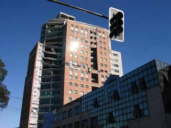
roof infill did not form a continuous diaphragm.

                                                                                      Column base failures revealed base anchor bars lapped with
                                                                                      column bars lacking standard hooks and a lack of confine-
                                                                                      ment reinforcement. The remaining debris also showed that
                                                                                      some sections were hollow, formed with expanded poly-
                                                                                      styrene cores. These gable frames lacked the strength and
                                                                                      ductility of special moment frames suitable for high seismic
     Figure 8. Precast concrete gable framed San José Fishery after the earthquake.   application.

                                                                                      It did not appear that this framing system was in common
      The gable frames were assembled using three standard                            use. The PCI team did not find any examples of this fram-
      parts, which include end columns, interior columns, and                         ing of more recent vintage than at the San José Fishery.
      drop-in gables (Fig. 9). The columns have monolithic knee
      joints and include parts of the sloping gable members.                          Precast and cast-in-place concrete
                                                                                      shear walls
      The roof was constructed over spaced precast concrete
      purlins that spanned between rows of these frames. The                          Based on the examples of precast concrete construction
      gable frame construction was similar to precast concrete                        that the PCI team was able to find, the industrial buildings
      frames that performed poorly in the 1999 earthquake near                        that were constructed with precast concrete often included
      Izmit, Turkey. There are a few notable differences. In Tur-                     precast concrete walls as cladding. Unlike the practice in
      key, the frame across the top of the column was a separate                      the United States, however, walls were not often used as
      precast concrete element spliced to the column and not cast                     the primary lateral-force-resisting system (LFRS). Exam-
      monolithically. The connections at the drop-in gables in the                    ples where walls provided the lateral bracing were found
      Turkish frames were pinned. The connections observed at                         in a pair of warehouse buildings that were constructed with
      the Chilean fishery were welded and apparently intended                         long-span gable beams on columns and clad with double-
      to provide strong connections for continuity. Some welded                       tee walls.
      connections failed by fracture of the reinforcement welded
      to the embedded parts for lap and development with the                          The bays were 39 ft (12 m) wide and 66 ft (20 m) long.
      precast concrete frame reinforcement. It is likely that the                     Gable-shaped girders spanned the 66 ft, and spaced precast
      bars were not weldable. Another difference was that the                         concrete purlins spanned the 39 ft. The ends of the girders
      Turkish precast concrete frames lacked any lateral bracing                      were fixed to the tops of the columns, but the purlins were
      perpendicular to the plane of the gable frame. At the Chil-                     pinned to the girders. The purlins were not continuous. At
      ean fishery, there were precast concrete diagonal braces in                     the outside edges, two-stemmed channels spanned between
      the end bays that remained standing. It is unclear whether                      the girder-column frames, providing a stiff lateral support to
      there was additional diagonal bracing in the collapsed bays,                    the exterior cladding made with precast concrete double-tee
      but it was reported that the collapse started in one corner                     walls. Figure 10 shows a building portion with this framing.
      and progressed across the building to the braced bays still                     At the front of the building, the tee stems were turned out,
      standing. The system of spaced purlins and light corrugated                     and at the rear they were turned in. Concrete planks spanned

     Figure 9. Gable frame system.

58                           W int e r 2 0 1 2 | PCI Journal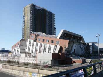
Roof plank

                                                                                                         Purlins
                            Edge channel                 Gable-shaped girder

                           Column

Figure 10. Framing system that uses long-span gable beams on columns and is clad with double-tee walls in an industrial building with offices.

 over the purlins, but there did not appear to be connections                           the other end, just inside the two-level bay with offices at
 between planks to form a diaphragm. There was no diagonal                              the front of the building. There were interior walls across
 bracing in the plane of the roof deck. The wall cladding was                           the building at the first bay that included two floors of of-
 connected to the precast concrete roof using long threaded                             fice space, but this did not provide effective bracing to the
 rods that connected to the channels on the sides and the                               framing at the distant end. The column-to-girder connec-
 girders at the ends. These connections appeared to provide                             tions apparently provided sufficient continuity for frame
 out-of-plane resistance but not a load path to transfer lateral                        behavior in the direction of the frame. Figure 11 shows a
 forces into the plane of the wall cladding.                                            sketch of the building plan.

 The shear walls for these buildings were isolated cast-in-                             The team learned from the owner’s representative that
 place concrete walls in two bays on each side. These bays                              one of the buildings had soil saturation problems during
 were the last short bay at one end and the second bay from                             construction that required soil improvement to a depth of

                                                Shear wall
                                                                                                                                            Shear wall

                                               Interior wall               Purlins

                                                                                                                         Purlins

                                                                           Girder

                                               Shear wall                                                                                   Shear wall
                             Office area (two levels)

Figure 11. Roof framing plan used in an industrial building with offices. Note: All measurements are in meters. 1 m = 3.28 ft.

                                                                                                                PCI Journal | Wi n t e r 2012            59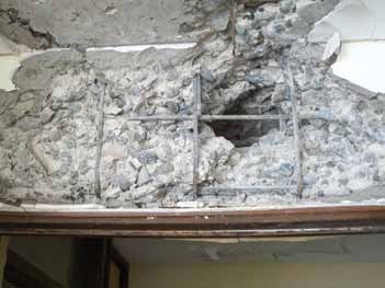
Figure 12. Front elevation of an office and warehouse building showing failed   Figure 14. Reinforced concrete column with bar buckling and lack of
     beam-column framing.                                                            confinement.

     Figure 13. Rear elevation of the same office and warehouse building showing     Figure 15. Bent and broken connection angle that failed to hold walls to edge
     fallen exterior walls and exposed transverse walls and end columns.             beam at roof.

      4.6 ft (1.4 m). The other did not. The structure without soil                   the front, with column spacing at about 20 ft (6 m) and
      improvement dropped the precast concrete purlins and roof                       stairways every 80 ft (24 m). Transverse walls separating
      in the two bays with cast-in-place concrete shear walls.                        the units were spaced at 40 ft (12 m), and the length from
      The other building did not suffer damage. It appears that                       front to back was from 66 ft to 82 ft (20 m and 25 m). The
      the lateral bowing in the roof girders caused a failure at the                  rear was enclosed by vertical precast concrete walls with
      pins and loss of bearing for the purlins.                                       loading docks and doors. Figures 12 and 13 show photos
                                                                                      of the collapse.
      Although many precast concrete buildings constructed
      using shear walls have performed well in past earthquakes,                      Although there appeared to be an ample number of walls
      the LFRS requires a complete load path that ties all compo-                     to provide lateral bracing for the structure, failures likely
      nents together. In this case, it appears that the roof framing                  occurred because of inadequate connections and a lack of
      with spaced purlins and without connections between roof                        seismic detailing for strength and ductility. Most of the
      planks lacked a diaphragm. Failures occurred at the pinned                      walls that clad the exterior of the stairs on the front eleva-
      purlin bearings where movement between the roof and the                         tion fell away from the structure because of out-of-plane
      supporting girders was not sufficiently restrained.                             forces that caused the connections to fail. Failed gravity
                                                                                      columns showed bar bucking and a lack of confinement
      Another combined office and warehouse consisting of a                           (Fig. 14).
      precast concrete building with transverse and longitudinal
      walls suffered major local failures and partial collapse.                       On the rear elevation, the tops of the walls were connected
      The structure had two-level beam and column framing on                          to the spandrel girders at the roof through a thin angle that

60                           W int e r 2 0 1 2 | PCI Journal
Figure 16. Misaligned wall-girder connection that failed.

 spanned between embedments in the walls and girders.            bays. The framing included precast concrete girders in both
 Figure 15 shows a remnant of bent and broken angle still        the longitudinal and transverse directions, bearing on top of
 welded to embedments in the back of the fallen spandrel         precast concrete columns with wet-cast joints. Figure 17
 panel. The welds to the plates embedded in the spandrel         shows one interior joint. The roof sloped from the sides
 girder were torn loose. Figure 16 shows that the continu-       to the center girder line. The roof deck was supported be-
 ous angle allowed the welds to be made even if the plates       tween the girders with simply supported precast concrete
 in the walls did not align with the plates in the spandrel      joists. The roof plane, in lieu of a diaphragm, had diagonal
 girder. The out-of-plane forces, however, caused bend-          bracing below the roof joists that was connected between
 ing in the angle and prying on the welds. There were also       girders to plates and gussets. The diagonal bracing was
 locations that appeared to have field-installed anchor rods     also composed of precast concrete joists, similar to those
 in the walls that projected into the cast-in-place concrete     in Fig. 18. The only significant damage to this structure
 topping over the roof. Walls had shallow breakout cones         from the earthquake was that all of these diagonal braces
 that appeared to correspond to short lengths of bent dowels     disconnected at the plates at the girders and fell.
 projecting from the edge of the topping. In addition, the
 walls were relatively thin, about 6 in. (150 mm), and the       The girders were formed as I-shaped sections with rect-
 wall reinforcement comprised at least three sizes of mild       angular end blocks, similar to bridge girders used in the
 steel reinforcement no larger than no. 3 (10M) bars.

 The structure may have had sufficient area of walls to sus-
 tain the lateral forces from the earthquake, but the connec-
 tions were insufficient in strength and ductility to support
 them against either in-plane or out-of-plane forces. The
 panel design deficiencies in thickness and in reinforcement
 may also have contributed to out-of-plane failures.

 Moment-resisting frames

 There were examples of precast concrete column and beam
 framing that had cast-in-place concrete closure joints that
 created continuity and formed moment-resisting frames.
 These systems generally performed well.

 One industrial building that used long-span girders with
 wet-cast joints was formed with 52 ft × 79 ft (16 m × 24 m)    Figure 17. Wet-cast joint between girders and column in an industrial building
                                                                that performed well during the earthquake.

                                                                                         PCI Journal | Wi n t e r 2012                           61
United States. This building was clad using vertically span-
ning precast concrete double-tee wall panels. The panels
were connected to the structure with long threaded rods
that projected across the open void formed by the I shape
and bolted through the webs. These connections provided
out-of-plane support, but they did not engage the cladding
as shear walls to provide any assistance to the LFRS.
The field-cast joints for the building were described as
having reinforcement projecting from the ends of the gird-
ers into the space over the tops of the columns with bar
laps and hooks that were engaged by the closure pour.
Other examples with similar framing and bracing were
found at the Weir Vulco plant. Figure 18 shows the precast
Figure 18. Diagonal precast concrete bracing for precast concrete girder roof
concrete diagonal framing in place. These buildings did
framing in an industrial building that did not experience structural damage dur-
ing the earthquake. not experience damage to the structural systems. Some
bracing for these buildings was provided by shear walls
that framed large door openings with drop-in walls over
the doors. Precast concrete column and beam framing
made continuous at the columns was also used for the con-
struction of 40 total–precast concrete schools and buildings
at five universities. No failures were reported in any of
these buildings.
The diaphragms and continuity of joints in these
systems were developed with cast-in-place concrete
topping for floors and wet joints. The floor framing
was constructed with precast concrete double-tees and
tapered end stems and flanges that formed the pocket for
the wet joint. Figure 19 shows a view of the underside
of this framing.
Cantilevered column systems
Figure 19. Total–precast concrete school framing system used in more than 40 There were several examples of industrial buildings with
schools that experienced no damage from the earthquake. precast concrete framing supported by cantilevered col-
umns as the LFRS.
One example in Santiago was a large exhibition hall. The
structure was framed with three consecutive bays, each
130 ft (40 m) long. It had eight 40-ft-wide (12 m) bays
spanned by spread precast concrete beams with a trap-
ezoidal section. Figure 20 shows an interior view of the
framing. The 130-ft girders are tapered I-beams that form
gable roofs. These beams bear on 40-ft columns and are
held with vertical rods that pin the ends to the bearings.
The columns are 35 in. (900 mm) square. Without moment
continuity between the ends of the beams or between the
beams and the columns, the lateral support for the structure
is provided by only the cantilever action of the columns at
the footings. The footings are not tied together with grade
beams, but the columns were designed for a combined
lateral force equal to 25% of the weight.
Figure 20. Interior of Espacio Riesco Exhibition Hall with cantilevered column
framing. The spread precast concrete beams do not form moment-
resisting frames, but they have wet-cast connections at
62 W int e r 2 0 1 2 | PCI JournalFigure 21. Interior view of the roof framing at a can factory. Figure 22. Base isolation bearings at Weir Vulco.
their bearings on the roof girders, so the secondary framing were fixed to the precast concrete columns with exterior
is made continuous. This detail adds some redundancy to plates bolted around the columns. The earthquake caused
the roof system and contributes to the overall structural the canopy to sag and the columns to crack near the beam
integrity. The spread-beam system, however, does not form connections. The cantilevered behavior of the columns
a continuous diaphragm capable of redistribution of the resulted in flexural cracks near the bottoms of the columns.
forces. The building suffered no structural damage to the The team also found that there were some local spalls at
primary LFRS. the bearing of a roof beam where the width of the beam
spanned across the joint between the ends of the roof gird-
This building was clad to about two-thirds of the exterior ers. The observed damage in these areas was not severe
wall height with horizontal precast concrete walls. These and was being repaired.
walls were not intended to act as shear walls, and some of
the upper panels fell from the structure as the cladding con- The design of cantilevered column systems was shown to
nections failed. This aspect is discussed in the section on be effective.
precast concrete cladding.
Advanced seismic-force-resisting
Another example of precast concrete framing with cantile- systems
vered columns was found in Coronel, south of Concepción,
at the Parque Industrial Escuadrón, adjacent to the failed There were several examples of framing systems using
gable frames described earlier. This recent construction advanced concepts that proved effective during the earth-
also used long-span gable-shaped roof girders and spread- quake.
beam framing to form a warehouse for the fish meal opera-
tion. The gable-shaped girders are pierced with round holes Base-isolated offices As a demonstration of lami-
in the webs to reduce their weight. Again, the trapezoidal nated base-isolation rubber bearings, the manufacturer con-
spread roof beams were made continuous across these gird- structed a total–precast concrete office building supported
ers with cast-in-place concrete joints. One section of this on slide bearings at the corners and on base isolators at the
building was about 52 ft (16 m) tall, with beams framing interior bays. Figure 22 shows a view of the isolation bear-
with pinned end connections at two levels above and below ings on one side.
the girders. This building survived the earthquake without
damage. The building is two bays by five bays, with a square
module of 26 ft (8 m). The structure is only two stories
A second example in Coronel was found at a manufactur- tall, but the company has supplied isolation bearings to
ing facility. The framing was similar to that of the fish meal fifteen other buildings with similar design. The structure
facility. Figure 21 shows an interior view of this building experienced no damage during the earthquake, though the
showing the gable-shaped girders and spread trapezoidal slide bearings showed movement of about 5 in. (130 mm)
roof beams. Field-cast joints created continuity in the roof in both longitudinal and transverse directions. The owner
beams across the girders. reported that books standing on end in the structure did not
fall over.
This structure was damaged in three areas. In one loca-
tion there was a long exterior cantilevered canopy over a It was reported that these bearings were used in some
loading area that was framed with steel beams. The beams residential buildings, some bridges, and at buildings at the
PCI Journal | Wi n t e r 2012 63Reinforced concrete braced frames with
cable-stayed roof The main building in the conven-
tion center complex is a large conference hall constructed
with precast concrete braced frames. The frames are tilted
in from the side walls so that the clear span at the floor level
is 200 ft (61 m) but the girder span for the roof is reduced
to 160 ft (49 m). Figure 23 shows an interior view of this
framing.
The clear height under the roof girders is 40 ft (12 m), and
they are 5 ft (1.5 m) deep. Roof beams span between the
girders to support the roof decking. Because of the long
spans of the girders, there is additional support provided
by cable stays. To hold these stays above the roof, columns
were added above the top intersection of the tilted braced
Figure 23. Interior view of a convention hall with tilted braced frames.
frame columns; these added columns lean outward. The
joints tying the lower and upper columns together were
made with field-cast concrete. Figure 24 shows an exterior
view of the cable stays, braced frames, and columns.
At one end of the hall, bracing columns extend to the
edge girder. At the other end, a large room for staging and
service support is framed with seven sides and clad to
about half the wall height with horizontal stacked precast
concrete wall panels. These cladding panels were not used
as lateral bracing for the structure and were connected to
columns with erection angles between slotted inserts. The
slots are oriented horizontally in the walls and vertically
in the columns, apparently to allow compensation during
erection for casting tolerance between walls and interior
framing. The roof for this side room is supported with
tapered precast concrete girders that span the width of the
room and are supported by, and cantilever over, another
Figure 24. Exterior view of a convention hall with braced frame and cable-stay interior long-span girder. This girder spans 160 ft (49 m)
supports.
and is 8 ft 2 in. (2.5 m) deep.
Catholic University and the University of Chile. They were The only damage to this building from the earthquake
used in a dock at the port of Coronel, which was reported was from failure of the cladding panel connections. It was
to be the only dock not damaged by the earthquake. reported that the top panels pulled out of plane and fell off
the structure. Some of the panels shown in the photograph
Unbonded prestressed concrete frames and were replaced temporarily while waiting for new panels
walls A precast concrete manufacturer constructed a five- with additional connections to be fabricated.
story structure at its convention/exhibition site that uses
unbonded post-tensioned walls and frames following the Precast concrete stadiums
research of the PCI PRESSS (Precast Seismic Structural
Systems) program. The structure is braced in the short The PCI team investigated stadiums framed with precast
direction by post-tensioned shear walls placed at the ends concrete columns, beams, rakers, and risers in Chillán and
of the building. The post-tensioning strands are located in nearby Chillán Viejo.
near the center of the walls. In the other direction, there are
three bays framed with unbonded post-tensioned moment- The stadium in Chillán was framed with precast concrete
resisting frames. Although the erection of the structure was for the seating areas on four sides enclosing the playing
complete, the building was unfinished. The first floor was in field. The seating was shaded with a fabric roof within
operation as a kitchen for the convention center. The upper steel frames supported by cantilevered steel columns
floors were not yet completed. The structure experienced no attached to the tops of precast concrete columns on the
damage from the earthquake. perimeter; these were braced by the raker beams and
transverse beam framing. The project was planned on a
tight schedule, and when the precast concrete manufacturer
64 W int e r 2 0 1 2 | PCI Journalcould not supply sufficient components, the framing of the
press box and supporting building was converted to cast-in-
place concrete, with a vertical line of separation at the back
of the seating area.
The precast concrete framing included rakers, columns,
beams, and single-step risers. Figure 25 shows a view of the
framing during erection. The precast concrete framing was
tied transverse to the rakers by beams with welded connec-
tions. With the exception of the failed roof structure falling
on the seating, the precast concrete framing withstood the
earthquake with only minor damage to bearing surfaces,
which showed some cracking. The primary failure occurred
at the connections at the tops of columns where the steel
framing for the fabric roof tore from column-base connec-
Figure 25. Stadium with precast concrete rakers on precast concrete columns.
tions and at some of the bracing cable anchor connections.
The failures occurred only at cast-in-place concrete columns
on the press box side of the stadium. buildings had lightweight non-diaphragm roofs and the
lateral forces were resisted by the column-beam framing
The stadium in Chillán Viejo was a smaller structure with system, sometimes with roof-level diagonal bracing, and a
precast concrete columns, rakers, and risers on opposite few cast-in-place concrete shear walls. The double-tees are
sides of the playing field. The framing was a simple single- commonly about 8 ft (2.4 m) wide and 30 ft (9.1 m) tall,
span raker on exterior columns. On one side, the seating with conventional (nonprestressed) reinforcing.
was backed up with a press box structure.
The team investigated two buildings with double-tee clad-
Damage to this stadium appeared to be relatively minor. ding. One used flat precast concrete panel cladding at the
There was a spall at the bearing of a riser stem at the top corners and double-tee walls along the sides. The other
of a raker where the bearing area was not confined, but used double-tee wall panel cladding that included walls
the concrete appeared to be intact over most of the bear- supported above a wide loading dock opening. In these two
ing length. There were also cracks at the bearing of a raker examples, the full-height double-tee wall panels were sup-
beam at a column corbel, but most of that bearing appeared ported on the foundation and with projecting reinforcing
intact. cast into the floor slab. Both the floor slab and an exterior
slab were cast against the base of the wall panel. Near the
It appeared that the precast concrete framing performed top of each double-tee leg, there were long bolt tiebacks
well during the earthquake. that projected through the interior perimeter beams
(Fig. 26). The bolts were more than 1 ft (0.3 m) long to
Performance provide out-of-plane restraint while allowing movement
of precast concrete cladding parallel to the wall of the framing system and the roof
and cladding connections system without transmitting force to the wall system.
In Chile, precast concrete cladding panels are used on At the convention center complex described previously, the
industrial buildings and on some low-rise office buildings. exhibition and convention halls were clad with long hori-
Precast concrete cladding was not observed on high-rise zontal precast concrete panels. The panels were stacked
structures. Most of the panels observed performed well. two to four units high, with the primary weight transferred
There were some cases where connections between the through the panel below and then to the foundation. One of
cladding and the supporting structure failed. the buildings had sloped precast concrete columns, creat-
ing a braced frame, so that part of the panel weight was
Most of the precast concrete cladding panels observed were carried by its connections to the columns (Fig. 23 and 24).
nonstructural. These panels were subject only to inertial The end annex to that building (Fig. 27) and the adjacent
seismic forces and wind loads. For effective support, the exhibit hall had vertically stacked panels. In neither case
connections of these panels should accommodate move- did the precast concrete walls reach the level of the roof.
ment of the supporting structure. Without this flexibility, Metal cladding was used to complete the enclosure.
cladding panels can attract unintended forces. Examples of
successful and unsuccessful performance were observed. The wall panels were attached to the concrete columns
with long slotted embedments (Fig. 28). The embedments
There were several warehouse-type buildings using vertical are commercial inserts commonly used for precast con-
double-tee wall panel cladding that performed well. These crete connections. The slotted inserts are oriented vertically
PCI Journal | Wi n t e r 2012 65Figure 26. Double-tee panel connection to perimeter beams used in industrial buildings.
in the columns and horizontally in the wall panels to provide
ample alignment tolerance. The connection appeared to be
for out-of-plane forces only. Although the photos show the
precast concrete wall panels in place, some of those panels
fell away from the buildings during the earthquake and were
replaced. As designed and installed, these connections did
not have sufficient strength to withstand the earthquake
forces. The slotted insert embedment had deformed at the
lips and allowed the bolts to pull out. One large all–precast
concrete multioccupant structure that was virtually de-
stroyed was described earlier in this report. The building’s
nonstructural precast concrete cladding was damaged or
simply collapsed. Cladding on the building was damaged as
the supporting structure failed. Exterior panels fell away due
to connection failures at the roof level.
Figure 27. Annex of Preansa Convention Hall uses horizontal precast concrete
panels. Precast concrete cladding was used on the steel-framed
structure of a building supply warehouse store in Con-
cepción. Panel collapse at this structure appeared to be
caused by the failure of the supporting structure. It was not
possible to determine whether inertial forces from the clad-
ding contributed to the failure.
An office structure in Concepción clad with precast con-
crete panels appeared intact, though much of the infill glass
was broken. Precast concrete cladding was also used on the
base-isolated Weir Vulco building. The base isolation of that
building protected the cladding as well as the structural pre-
cast concrete framing. Other buildings with precast concrete
wall cladding were observed from a distance to have been
damaged, but with access limited, the configuration and the
extent of damage could not be determined.
In general, the precast concrete cladding panels in Chile
performed well when the effects of and requirements for
Figure 28. Slotted inserts to connect wall panels to concrete columns and the seismic resistance were considered in design and detailing.
deformation of the slotted inserts due to the earthquake load.
66 W int e r 2 0 1 2 | PCI JournalFigure 29. Bridge section showing recent construction practice that eliminates the transverse diaphragm and uses vertical steel rods to prevent overturning.
Precast concrete bridges
Many highway bridges in Chile are constructed with pre-
cast concrete I-girders or bulb-tee sections. Many of these
crossings performed well, but there were also many notable
failures that shared common characteristics.
Precast concrete
bridge construction
Moderate-span precast concrete bridges in Chile are con-
structed using I-girder or bulb-tee girder shapes, similar to
AASHTO sections used in the United States. The design
includes cast-in-place concrete diaphragms between gird-
ers. The girders bear in pockets with direct lateral restraints
against displacement at each girder. The diaphragms tie Figure 30. Failed bearing in the Llacolen Bridge.
the girders together laterally and prevent overturning from
lateral loads above the bearings. configuration are more susceptible to loss of bearing, the
geometry of the rigid concrete deck must contact the piers
Local engineers reported that design practice for these or abutments and cause some lateral displacement of the
bridges changed in the late 1990s following Spanish prac- support for the rotation to continue. This strongly suggests
tice so that diaphragms providing lateral support between that a lack of longitudinal restraint of these bridge girders
girders were reduced or eliminated. Lateral support at the at the abutments or piers at one end of the span at least
bearings was reduced to end stoppers at the ends of the contributed to these failures.
piers or abutments, constructed with small reinforced con-
crete sections projecting above the beam bearing surface. Bridge inspection
Vertical steel rods from the bearing to the underside of the
upper flange of the girders compensate for the loss of over- The PCI team inspected two bridges in Concepción. The
turning resistance. Figure 29 shows a section representing first bridge was the Llacolen Bridge, which includes sev-
these features of precast concrete bridge design. eral moderate-length spans across the Bio Bio River. This
bridge was constructed without diaphragms between the
The bridges with designs based on the more recent practice girders at the piers. The construction included the vertical
experienced more damage than bridges constructed with restraint bars enclosed in galvanized steel tubes. Figure 30
traditional details. The more recent bridges suffered lateral shows the bearing surface with concrete debris and twisted
displacements at the bearings, failure in end stoppers, and reinforcing from the failed girders and deck. The photo
some overturning of the beams. also shows the bent and twisted galvanized tubes that held
the failed restraint bars.
Bridges with skewed bearings failed because a lack of lat-
eral restraint permitted the global rotation of the bridge and As seen in the photo, the bridge girders pulled away from
allowed the beams to fall from the bearings. The absence the bearing and dropped the end of the span. This was
of lateral restraints at the bearings is not sufficient to pro- not a skewed span, but the span lacked both lateral and
vide a mechanism for collapse. Although bridges with this longitudinal restraint at this bearing. The length of the
PCI Journal | Wi n t e r 2012 67Diaphragm
Figure 31. Bridge section at the Bio Bio River crossing with partial diaphragms, vertical restraint bars, and end stoppers.
bearing was not sufficient for the longitudinal displacement The abutment bearing was cast as a level ledge, and then
between the piers. This was one of several failed multispan the bearing blocks with varying thicknesses were placed
bridges that dropped the ends of spans. to form the final bearing elevations. This convenient
method used to construct the correct bearing elevations
Figure 30 also shows an elevated bearing surface that is lacks the lateral restraint of bearing details using pockets.
a reminder that actual construction geometry is often not The earthquake forces caused lateral displacement and the
as simple as the illustration of the geometry shown in the failure of the stopper at one end of the pier. The failure did
earlier figures. not indicate a lack of reinforcing, though the horizontal
confinement did not appear to contain all of the vertical
Figure 31 shows another bridge section that includes reinforcement. The design, however, imposed all the re-
the center crown and cross slope for drainage that must quirement of lateral restraint on the end stopper. Figure 33
often be included. It is common for the beam bearings shows the failed stopper at the abutment. This view also
to be stepped to provide the crowned shape or to provide shows a wide crack in the bottom of the edge girder from
for cross slope or superelevation in the roadway above. the impact with the stopper.
These features of practical geometry can result in the loss
of lateral restraint to the girders; this was observed in the A bridge in Santiago designed with vertical restraint bars
Llacolen Bridge. The second bridge was a multispan bridge attached to precast concrete girders and bridge pier showed
crossing an inlet of the Bio Bio River. no evidence of displacement. Damage at this bridge was
seen in subsidence of the fill that formed the bridge ap-
This bridge had some of the characteristics of more recent proach and embankment at the grade separation.
bridge construction details but did include partial-depth
diaphragms between the girders at the bearings. Figure 31 Building code
also includes the diaphragms, the vertical restraint bars,
and the end stoppers. Figure 32 shows a view of the bear- Buildings and other structures in Chile must be designed
ing at two interior girders. and constructed in compliance with the Chilean Building
Code NCh433-2009.6 This code is applied in addition to
the specific design code for each of the materials and aims
to achieve structures that meet the following objectives:
• resist moderate intensity of seismic actions without
damage
• limit damage to nonstructural elements during earth-
quakes of moderate intensity
• prevent collapse during earthquakes of severe inten-
sity, even though they show some damage
Compliance with the provisions of this code does not guar-
antee that the objectives will be achieved.
In particular, the provisions for reinforced-concrete-wall
Figure 32. Lateral displacement due to earthquake forces of the Bio Bio River buildings are based on their satisfactory behavior dur-
bridge with partial diaphragms and vertical restraint bars.
68 W int e r 2 0 1 2 | PCI JournalTable 2. Soil parameters for base shear calculation in NCh433-2009
Soil type S T', sec n
I 0.9 0.20 1.00
II 1.0 0.35 1.33
III 1.2 0.85 1.80
IV 1.3 1.35 1.80
Note: n = soil parameter for base shear calculation indicated in
Where is the referencef for these tables?
NCh433-2009; S = site coefficient; T' = soil parameter for base shear
calculation indicated in NCh433-2009.
Table 3. Maximum values of seismic coefficient C in NCh433-2009
R Cmax
2 0.90SA0 /g
3 0.60SA0 /g
4 0.55SA0 /g
5.5 0.40SA0 /g
6 0.35SA0 /g
7 0.35SA0 /g
Note: A0 = maximum effective acceleration value; Cmax = maximum
seismic coefficient; g = acceleration due to Earth’s gravity; R = reduc-
Figure 33. Failed stopper at the abutment of the Bio Bio River bridge, with a
crack in the bottom of the girder. tion factor ranging from 2 for structural systems of limited ductility to 7
for ductile structural systems; S = site coefficient.
ing the earthquake of March 1985. Those buildings were
designed in accordance with NCh433-1972.18
type I is rock; soil type IV is soft soil.
The Chilean seismic code NCh433-199611 was in effect
until it was replaced by the 2009 update (NCh433-2009)6 The base shear Qo is determined from Eq. (1).
shortly before the earthquake. A 2010 update has been
developed in direct response to the earthquake. Qo = CIP (1)
NCh433-20096 has four building categories: A, B, C, The seismic coefficient C is obtained from Eq. (2).
and D. These are comparable to ASCE 7/05 occupancy
2.75A0 a T lk
categories IV (essential facilities, hazardous facilities), III n
(high-occupancy buildings where many people congregate C= (2)
in one space at one time), II (standard-occupancy buildings gR a T * kn
such as office buildings and apartments), and I (miscella-
neous-occupancy buildings where no life safety is at stake),
respectively. The importance factor I for building types A, In no case shall the value of C be less than A0/6g.
B, C, and D is 1.2, 1.2, 1.0, and 0.6, respectively.
The value of C need not be greater than that indicated in
The country is divided into three seismic zones: zone 1 is Table 3.
along the foothills of the Andes, zone 3 is along the Pacific
coast, and zone 2 is between zones 1 and 3. The maximum There are no specific provisions for or prohibition of build-
effective acceleration values A0 corresponding to zones 1, ings with structural irregularities.
2, and 3 are 0.20g, 0.30g, and 0.40g, respectively.
ACI 318-95 seismic provisions were referenced by
NCh433-1996 considers four soil types: I, II, III, and IV NCh433-199611 in annex B, except the confinement re-
(Table 2). These are comparable to soil profile types S1, S2, quirements for wall boundaries were specifically exempted
S3, and S4, respectively, in UBC editions before 1997. Soil in clause B.2.2 as previously discussed. This clause has
PCI Journal | Wi n t e r 2012 69Figure 34. Longitudinal and transverse reinforcing bar diameter limitations. Note: bw = thickness of wall; db = nominal diameter of longitudinal bar; dbt = nominal
diameter of transverse bar; fy = yield strength of longitudinal reinforcement; fyt = yield strength of transverse reinforcement.
been deleted from NCh433-2009.6 • Studies should be nonlinear-analytical and experi-
mental. Analytical results should be compared with
The following changes19 to NCh433-20096 were being observations and new findings that confirm or reject
considered and were in draft form at the time of the team’s the proposed explanations.
visit:
• A building responds to an earthquake with the struc-
• Limit axial forces on columns and walls that are sub- ture as constructed and with material properties that
ject to lateral displacements to 0.35 fclAg . exist at the time of the earthquake. This may be obvi-
ous but is often ignored.
• All hooks on hoops and cross ties of confinement rein-
forcement should be 135° rather than 90°. At a presentation before ACI 318 subcommittee H in Oc-
tober 2010, Bonelli discussed the following changes made
• Confine at least 0.15ℓw from each edge and laterally to ACI 318-0816 requirements in the emergency changes to
support every vertical bar, not just every other one. NCh433-20096,21 and NCh430-2008:22,23
• Apply capacity design concepts to determine axial 1. The whole flange width of a flanged section (T, L, C,
force and shear, considering the effect of connection or other cross-sectional shapes) must be considered in
with the slabs. calculating combined flexural and axial load strength.
• Add slenderness restrictions to avoid transverse bend- 2. The contribution of the total amount of longitudinal
ing of boundary elements and the panel. For this, study reinforcement must be considered in determining
the New Zealand19 and Canadian20 code recommenda- combined flexural and axial load strength.
tions.
3. Longitudinal reinforcing bar diameter must be less
• Revise the displacement spectrum. than or equal to one-ninth of the least dimension of
the boundary element (wall thickness) (Fig. 34).
• Avoid adding to the resistance side; add to the demand
side. Study the effect of resistance (strength) on dis- 4. Transverse reinforcing bar diameter must be greater
placement demand. than or equal to one-third of the diameter of the re-
strained longitudinal bar (Fig. 34).
• Optional displacement-based design has been intro-
duced in annex B. 5. Transverse reinforcement must be anchored to ex-
treme longitudinal bars in a wall.
Patricio Bonelli, a professor at Universidad Técnica Fed-
erico Santa María, also shared the following recommenda- 6. Standard hooks must be used with transverse rein-
tions and reflections: forcement as defined in section 7.1 of ACI 318-08:
135° or 180° bend plus 6db extension, but not less than
• Carefully study the demands of displacement and 3 in. (75 mm) at the free end of the bar. In ACI 318-
rotation. In Concepción, 15 cycles of 0.2g acceleration 08,16 a standard hook is defined as a 180° bend plus
were observed at a period of 1.5 sec. 4db extension or a 90° bend plus 12db extension. Thus,
these two requirements are contradictory. The second
• Microzonation of cities is desirable. requirement (135° or 180° bend plus 6db extension),
70 W int e r 2 0 1 2 | PCI JournalYou can also read